CN1147031C - Multiband antenna - Google Patents
Multiband antenna Download PDFInfo
- Publication number
- CN1147031C CN1147031C CNB00800353XA CN00800353A CN1147031C CN 1147031 C CN1147031 C CN 1147031C CN B00800353X A CNB00800353X A CN B00800353XA CN 00800353 A CN00800353 A CN 00800353A CN 1147031 C CN1147031 C CN 1147031C
- Authority
- CN
- China
- Prior art keywords
- antenna
- antenna assembly
- short
- circuit unit
- frequency
- Prior art date
- Legal status (The legal status is an assumption and is not a legal conclusion. Google has not performed a legal analysis and makes no representation as to the accuracy of the status listed.)
- Expired - Lifetime
Links
Images

Classifications
-
- H—ELECTRICITY
- H01—ELECTRIC ELEMENTS
- H01Q—ANTENNAS, i.e. RADIO AERIALS
- H01Q21/00—Antenna arrays or systems
- H01Q21/30—Combinations of separate antenna units operating in different wavebands and connected to a common feeder system
-
- H—ELECTRICITY
- H01—ELECTRIC ELEMENTS
- H01Q—ANTENNAS, i.e. RADIO AERIALS
- H01Q19/00—Combinations of primary active antenna elements and units with secondary devices, e.g. with quasi-optical devices, for giving the antenna a desired directional characteristic
- H01Q19/10—Combinations of primary active antenna elements and units with secondary devices, e.g. with quasi-optical devices, for giving the antenna a desired directional characteristic using reflecting surfaces
-
- H—ELECTRICITY
- H01—ELECTRIC ELEMENTS
- H01Q—ANTENNAS, i.e. RADIO AERIALS
- H01Q5/00—Arrangements for simultaneous operation of antennas on two or more different wavebands, e.g. dual-band or multi-band arrangements
- H01Q5/50—Feeding or matching arrangements for broad-band or multi-band operation
-
- H—ELECTRICITY
- H01—ELECTRIC ELEMENTS
- H01Q—ANTENNAS, i.e. RADIO AERIALS
- H01Q9/00—Electrically-short antennas having dimensions not more than twice the operating wavelength and consisting of conductive active radiating elements
- H01Q9/04—Resonant antennas
- H01Q9/16—Resonant antennas with feed intermediate between the extremities of the antenna, e.g. centre-fed dipole
Abstract
The invention relates to an improved multiband antenna for transmission and reception in which the combiner circuit, which is necessary under the state of the art, is simplified. According to the invention no separate band-pass filters are required. Instead the band-pass filters are provided by the configuration of the antenna itself. The above multiband antenna is also characterized in that the frequency-selective components (11', 11'') are each integrated into the corresponding antenna device (7', 7'') and said frequency-selective components (11', 11'') for each corresponding dipole antenna device (7', 7'') are provided with a dipolar structure which is created by appropriate configuration of the active electrical length of the corresponding balancing element (25, 31) and the electrical length of the branch line (5, 5'') between the branching point (5) and the infeed point of the corresponding antenna device (7, 7'').
Description
Technical field
The present invention relates to a kind of multiband antenna, have at least one first and at least one second antenna assembly, be used for emission or reception, wherein at least the first and at least the second antenna assembly have dipole structure, and half dipole wherein is mounted and/or is maintained at by symmetric part on a substrate or the reflector, wherein connect and realize the signal feed-in by a community antenna input lead and a branch, also be provided with at least two frequency selected cells, each frequency selected cell blocks the frequency band range that transmits by other antenna assembly.
Background technology
The mobile wireless electric frequency band overwhelming majority is by the GSM900 net, promptly with the 900MHz band spreading.Also set up the GSM1800 standard in addition, in this standard, can receive and send the signal of 1800MHz.
Therefore the base station of this multiband needs multiband antenna to send and to receive different frequency ranges, this antenna has dipole structure usually, another dipole antenna device that promptly is used to send and receive a dipole antenna device of 900MHz frequency band range and is used to send and receive the 1800MHz frequency band range.
On Fig. 1, summarily provided according to the known antenna assembly of prior art.
A kind of like this antenna assembly comprises a community antenna input 1, is connected with a combinational circuit 3 on its back antenna side, is used for being implemented in the decoupling of the signal that the different frequency bands scope transmits.
The back of this combination or branch circuit 3 is connected with two offsets 5 ' and 5 ", they are directed to first antenna assembly 7 ' on the one hand and are directed to second antenna assembly 7 on the other hand " so that carry out radio communication with first and second frequency band range thereon.
This branch circuit 3 is provided with integrated frequency alternative pack for this reason, and for example a kind of band pass filter, it will make two offsets 5 ' and 5 " respectively block the frequency band range of another antenna assembly each other.
Summary of the invention
Task of the present invention is, creates a kind of not only simple in structure but also rational two frequency-band antennas of cost of comparing with it from described prior art.
This task will solve by following measure according to the present invention: the frequency selected cell is integrated in the corresponding antenna assembly, and the frequency selected cell that is used for dipole antenna device under each by the relevant antimeric effective electrical length of design correspondingly, and breakout and the electrical length that is provided with the affiliated offset between the load point on the affiliated antenna assembly of dipole structure form.
According to a kind of preferred design of the present invention, in the middle of half part of two symmetries of first or second antenna assembly, be provided with half short-circuit unit that partly is connected with these two symmetries.
According to another kind of improvement project be, first and second antenna assemblies or radiator are kept by a reflector, wherein the height of this holding device is greater than the antimeric effective electrical length of affiliated antenna assembly, and this effective electrical length is determined by the distance between radiator and the affiliated short-circuit unit.
Preferably, short-circuit unit is by conducting block, and conducting bridge, especially metal derby are formed, and the thickness of short-circuit unit is corresponding to the distance of half part of affiliated each symmetry.
Preferably, short-circuit unit is welded between half part of two symmetries.
Preferably, short-circuit unit is made up of folder and/or screw piece.
According to a kind of preferred implementation, antenna input lead and offset are made to coaxial cable.
Must show that unexpected and surprised fully is to abandon using traditional combination or branch circuit.Also need according to the present invention with the frequency alternative pack be different from prior art, it is not to utilize the element that is integrated in separately in the combinational circuit to realize, and they can be integrated in this antenna assembly itself according to the present invention.
The effective conductance body length of the respective antenna device that respective element integrated in antenna assembly can be only begins by the symmetric part setting of respective antenna device and from breakout realizes, and do not need as element separated in the prior art.
Be proved and particularly advantageously be, this antimeric adaptively changes by the adjustment that is installed in the short circuit part in the middle of the symmetric part.Size and layout by this short circuit part can make antimeric effective electrical length adaptive in this wise, each frequency selective element (for example band pass filter) that promptly is integrated in the respective antenna device is used for the frequency of second antenna assembly of another frequency band range with obstruction, promptly is operated in Light Condition.
Below will describe the present invention in detail by an embodiment.
Description of drawings
Fig. 1: be used to illustrate general block diagram according to one two frequency-band antenna of prior art;
Fig. 2: relatively Fig. 1 changed, be used to illustrate general block diagram according to two frequency-band antennas of the present invention;
Fig. 3: be used to illustrate circuit theory diagrams according to the working method of two frequency-band antennas of the present invention;
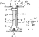
Fig. 4: according to the summary cross-sectional view of an embodiment of two frequency-band antennas of the present invention;
Fig. 5: a summary side view of two frequency-band antenna devices shown in Fig. 4 is used to further specify the adaptive of a short circuit part and arrange; And
Fig. 6: along the summary profile of Fig. 5 Vertical Centre Line VI-VI.
Embodiment
Fig. 2 is different from, two frequency-band antennas as in Fig. 1 provide known according to prior art, its expression: replaced original branch circuit according to the present invention and only be provided with a breakout or summing junction, below be also referred to as asterism 5, an antenna input lead 1 ' is branched into two offsets 5 ' and 5 at that point ".
These two offsets 5 ' and 5 " each be connected to two antenna assemblies 7 ' and 7 ", each antenna assembly comprises the radiator 9 ' and 9 with dipole structure ", be the form (Fig. 4) of two λ/2 dipoles in illustrated embodiment.
At this radiator 9 '; 9 " in each integrated virtually frequency selected cell 11 ' of setting up, 11 ", it is by by double radiator 9 ', 9 " symmetry and the electric conductor length role between the load point of breakout 5 and affiliated double radiator determine.
As appreciable from schematic diagram according to Fig. 3, feed-in for a kind of like this two frequency-band antennas is by a public antenna input 1, promptly public antenna input lead 1 ' is realized, the frequency signal that its input is transmitted in GSM900 and GSM1800 frequency range.The feed-in of this signal is preferably by coaxial conductor, here in Fig. 3 for circuit theory is described, this coaxial conductor, to be inner wire and outer conductor provide as the connection of two conductors.
At corresponding radiation resistance 10 ' and 10 " situation under; for example the form of an available band pass filter is adaptive in this wise and optimize for the required frequency selected cell of the antenna of GSM900 and GSM1800 now; promptly always constitute two resonant tanks 13 '; 13 ", each resonant tank of frequency for another antenna gets clogged, and promptly is operated in Light Condition.For this reason, as described in just now, at breakout or asterism 5 and affiliated antenna assembly 7 '; 7 " corresponding load point between offset 5 '; 5 " electrical length and comprise from load point 12 ' or 12a " to the rearmounted length of the following short dot that will explain; itself and value will be selected according to formula given below so that described frequency selected cell or band pass filter their respectively can be satisfied best according to the following formula that also will discuss for corresponding blocking performance of another antenna frequency band range.
Hereinafter with reference to Fig. 4, it relates to a specific embodiment.
In Fig. 4, express one two frequency-band antenna with the form of vertical cross-section synoptic diagram, it is installed in one as reflector 19 and also as constituting on the substrate that antenna assembly uses, wherein this two frequency-band antenna be provided with one removable and can see through the shell 21 of electromagnetic radiation as waves.
Be provided with first antenna assembly 7 ' in the inside of shell 21, promptly according to first radiator 7 ' of the form GSM1800 standard operation and that have a dipole 23.Two and half dipole 23a and 23b are positioned at the upper end of a respective holder 24, in the illustrated embodiment, two and half support 24a are wherein arranged, 24b constitutes one and reaches by corresponding bending and the moulding of seamed edge part, and constitute a bottom, carry out the transition to half support 24a, the leg of 24b or be anchored section 27, it is kept reliably by screw 28 that is screwed into from the below for example and is fixed on (Fig. 5) on the reflecting plate 19.This two and half dipoles 23a and 23b reach the symmetric part that constitutes dipole 23 with a section that is positioned at above the short circuit part to be illustrated 41 ' by half part 25a and the 25b supporting and the maintenance of two symmetries.Correspondingly this also is applicable to second antenna assembly 7 " support 30.Here half part 31a of two symmetries and 31b are equally by being positioned at a short circuit part 41 among support half part 30a and the 30b " top section formation.
The height of dipole and length will be adjusted according to frequency band range to be sent and radiation diagram, then be adjusted to the band region of 1800MHz in this embodiment.
Need, in the antimeric upper end of each antenna assembly a non-conductive fixture 35 can be set, it makes half part of two symmetries fixing relative to one another, and this only is used for improving the stability (Fig. 5) of antenna assembly.
A public coaxial cable 1 ' is directed on breakout or the asterism 5, as also representing in Fig. 4 at first from the not detailed coaxial tie point 1 of representing among Fig. 4.
Right latter two offset 5 '; 5 " be connected to two radiators 7 ' from these asterism 5s; 7 " these two offsets 5 ', 5 wherein " in each symmetric halves that in illustrated embodiment, is parallel to radiator 7 ' in fact divide 25b and radiator 7 " symmetric halves divide 31b and near the two extension.As appreciable from accompanying drawing, load point is normally such on this dipole antenna, promptly (especially can see) coaxial offset 5 ' and 5 from the general diagrammatic sketch of Fig. 5 " outer conductor 5 ' a and 5 " a is at one and half dipoles, be electrically connected on the load point 12 ' a as the height of half dipole 23b, and surpass the inner wire 5 ' b that this corresponding half dipole 23b stretches out (or antenna assembly 7 " inner wire 5 " b) connect bridge plate 39 ' (or 39 ") by one and form with the second half dipole 23a or 29a on the side within it and be electrically connected.Can realize required known symmetrical load point 12 ' (or 12 ") thus.
At last, two symmetric halves of first antenna assembly 7 ' divide between 25a and the 25b and at second antenna assembly 7 " two symmetric halves divide respectively be provided with a described short circuit part 41 ' and 41 between 31a and the 31b ", length and layout for them will be selected in this wise, promptly by they can adjust constitute one (integrated), as the frequency selected cell 11 ' and 11 of band pass filter type ", block mutually so that these two radiators are these two frequency selected cells.Therefore, can realize that by the frequency selected cell of such formation consequently another frequency selected cell (band pass filter) is worked unloadedly for another frequency band range to the blocking action of the frequency band range that is sent or received by another radiator.By described short circuit part 41 ' and 41 " antimeric effective length will be limited in from corresponding short circuit part 41 ' or 41 " upside last to the distance of the height of double radiator 23 or 29.In other words, reflector itself is located on the height (being the upside of short circuit part) of this short circuit part.
The electrical length of antenna or offset 5 ' add from feed-in position 12 ' or 12 ' a to the antimeric electrical length (here corresponding to antimeric length) of short circuit part 41 ', or antenna or offset 5 " respective electrical lengths add from feed-in position 12 " or 12 " a is to short circuit part 41 " antimeric length be configured to a length, promptly itself and value each satisfy following formula:
The electrical length of first antenna assembly 7 ', 9 ':
L1 (GSM1800)=λ
2/ 4+n (λ
2/ 2) reach
L2(GSM900)=λ
1/4+n·(λ
1/2)
λ in the formula
2Be wavelength corresponding to second frequency band range of GSM900 standard (in the present embodiment), and λ
1Be wavelength corresponding to first frequency band range of GSM1800 standard (in described embodiment), but n value 0,1,2,3 in the formula ..., promptly n is one and comprises 0 natural number.In other words, for example for first antenna assembly 7 ' of GSM1800 standard, total electrical length of 9 ' depends on the wavelength of the frequency band that sends by second antenna assembly, and total electrical length of second antenna assembly depends on the wavelength of the frequency band that sends by first antenna assembly.
Can only pass through according to described embodiment; 5 affiliated offset 5 ' " corresponding sizing and with short circuit part 41 ' under each, 41 " be arranged in two corresponding symmetric halves and divide 23a; 23b or 29a; on the proper height in the middle of the 29b; promptly be arranged on the suitable distance of half dipole, form an integrated band pass filter, and do not need with discrete additional band pass filter means.
Because as mentioned above, add from this load point to affiliated short circuit part 41 ' in total electric conductor length from load point on breakout 5 processes to corresponding half dipole height, the length of upper end 41 " is confirmed as realizing blocking or the size of unloaded function, and the length and the width of this short circuit part can differently constitute.Therefore corresponding short circuit part 41 ', 41 " length or highly also different selections can be arranged, wherein this short circuit part also is used for the mechanical strength and the rigidity of total, for example also plays the effect of required vibration damping.
This embodiment is used for illustrating one two frequency-band antenna, but this embodiment also can be diverted to the antenna that comprises more than two frequency bands at large, promptly is used for multiband antenna at large.
Claims (8)
1. multiband antenna, have at least one first antenna assembly (7 ') and at least one second antenna assembly (7 "), be used for emission or receive, wherein at least the first antenna assembly (7 ') and at least the second antenna assembly (7 ") have dipole structure, and half dipole (23a, 23b wherein; 29a, 29b) by its symmetric part (25,31) be mounted and/or be maintained on a substrate or the reflector (19), wherein realize the signal feed-in by a community antenna input lead (1 ') and a breakout (5), also be provided with at least two frequency selected cells (11 ', 11 "), each frequency selected cell blocks the frequency band range that transmits by other antenna assembly, it is characterized in that:
The frequency selected cell (11 ', 11 ") be integrated in the corresponding antenna assembly, and
The frequency selected cell (11 ' that is used for each affiliated dipole antenna device, 11 ") the effective electrical length by the relevant symmetric part (25; 31) of design correspondingly, and breakout (5) and the affiliated antenna assembly that is provided with dipole structure on load point (12 ', 12 ' a; 12 ", the 12 " electrical length of the affiliated offset between a) (5 ', 5 ") and forming.
2. according to the multiband antenna of claim 1, it is characterized in that: at half part of two symmetries of first antenna assembly (7 ') or second antenna assembly (7 ") (25a; 25b or 31a; be provided with half a partly (25a; 25b or 31a; the short-circuit unit that 31b) is connected (41 ', 41 ") with these two symmetries 31b).
3. according to the multiband antenna of claim 2, it is characterized in that: the radiator of first and second antenna assemblies (7 ', 7 ") or first and second antenna assemblies (9 ', 9 ") keep by a reflector (19), wherein holding device (24; 30) height is greater than the effective electrical length of affiliated antenna assembly symmetric part (25,31), this effective electrical length by radiator (9 ', 9 ") and under distance between the short-circuit unit (41 ', 41 ") determine.
4. according to the multiband antenna of claim 2 or 3, it is characterized in that: short-circuit unit (41 ', 41 ") by conducting block, conducting bridge is formed, and the thickness of short-circuit unit is corresponding to half part (25a, 25b of affiliated each symmetry; 31a, distance 31b).
5. according to the multiband antenna of claim 2 or 3, it is characterized in that: short-circuit unit (41 ', 41 ") to form by metal derby, the thickness of short-circuit unit is corresponding to half part (25a, 25b of affiliated each symmetry; 31a, distance 31b).
6. according to the multiband antenna of claim 2 or 3, it is characterized in that: short-circuit unit (41 ', 41 ") is welded in half part (25a, 25b of two symmetries; 31a, 31b) between.
7. according to the multiband antenna of claim 2 or 3, it is characterized in that: short-circuit unit (41 ', 41 ") form by folder and/or screw piece.
8. according to each multiband antenna in the claim 1 to 3, it is characterized in that: antenna input lead (1 ') and offset (5 ', 5 ") are made to coaxial cable.
Applications Claiming Priority (2)
| Application Number | Priority Date | Filing Date | Title |
|---|---|---|---|
| DE19912465.5 | 1999-03-19 | ||
| DE19912465A DE19912465C2 (en) | 1999-03-19 | 1999-03-19 | Multi-area antenna system |
Publications (2)
| Publication Number | Publication Date |
|---|---|
| CN1296651A CN1296651A (en) | 2001-05-23 |
| CN1147031C true CN1147031C (en) | 2004-04-21 |
Family
ID=7901684
Family Applications (1)
| Application Number | Title | Priority Date | Filing Date |
|---|---|---|---|
| CNB00800353XA Expired - Lifetime CN1147031C (en) | 1999-03-19 | 2000-03-16 | Multiband antenna |
Country Status (13)
| Country | Link |
|---|---|
| US (1) | US6323820B1 (en) |
| EP (1) | EP1078424B1 (en) |
| KR (1) | KR100454142B1 (en) |
| CN (1) | CN1147031C (en) |
| AT (1) | ATE242553T1 (en) |
| AU (1) | AU760267B2 (en) |
| BR (1) | BR0005455A (en) |
| CA (1) | CA2332630C (en) |
| DE (2) | DE19912465C2 (en) |
| DK (1) | DK1078424T3 (en) |
| HK (1) | HK1035607A1 (en) |
| NZ (1) | NZ507669A (en) |
| WO (1) | WO2000057514A1 (en) |
Families Citing this family (24)
| Publication number | Priority date | Publication date | Assignee | Title |
|---|---|---|---|---|
| EP1509969A4 (en) * | 2002-03-26 | 2005-08-31 | Andrew Corp | Multiband dual polarized adjustable beamtilt base station antenna |
| US6765542B2 (en) | 2002-09-23 | 2004-07-20 | Andrew Corporation | Multiband antenna |
| US6836258B2 (en) | 2002-11-22 | 2004-12-28 | Ems Technologies Canada, Ltd. | Complementary dual antenna system |
| US6975278B2 (en) * | 2003-02-28 | 2005-12-13 | Hong Kong Applied Science and Technology Research Institute, Co., Ltd. | Multiband branch radiator antenna element |
| CN100463290C (en) * | 2003-08-05 | 2009-02-18 | 佳邦科技股份有限公司 | Multifrequency antenna module and its wireless transmission device |
| US7034769B2 (en) * | 2003-11-24 | 2006-04-25 | Sandbridge Technologies, Inc. | Modified printed dipole antennas for wireless multi-band communication systems |
| US6924773B1 (en) | 2004-09-30 | 2005-08-02 | Codman Neuro Sciences Sarl | Integrated dual band H-field shielded loop antenna and E-field antenna |
| CN100397704C (en) * | 2004-11-25 | 2008-06-25 | 刘正芳 | Multiple frequency-band planar antenna |
| US7683839B2 (en) * | 2006-06-30 | 2010-03-23 | Nokia Corporation | Multiband antenna arrangement |
| US7724201B2 (en) * | 2008-02-15 | 2010-05-25 | Sierra Wireless, Inc. | Compact diversity antenna system |
| KR20150110291A (en) | 2013-01-30 | 2015-10-02 | 갈트로닉스 코포레이션 리미티드 | Multiband hybrid antenna |
| CN103730728B (en) * | 2013-12-31 | 2016-09-07 | 上海贝尔股份有限公司 | Multifrequency antenna |
| ES1291234Y (en) | 2014-04-11 | 2022-08-30 | Commscope Technologies Llc | Multiband antenna adapted to eliminate resonances |
| CN105337041A (en) * | 2015-09-29 | 2016-02-17 | 大连海事大学 | Full-band television transmitting antenna based on rhombic oscillators |
| WO2017091993A1 (en) * | 2015-12-03 | 2017-06-08 | 华为技术有限公司 | Multi-frequency communication antenna and base station |
| CN108281757A (en) * | 2017-01-06 | 2018-07-13 | 罗森伯格技术(昆山)有限公司 | Antenna for base station for high frequency decoupling |
| NO20170110A1 (en) * | 2017-01-25 | 2018-07-26 | Norbit Its | Wideband antenna balun |
| KR101750336B1 (en) * | 2017-03-31 | 2017-06-23 | 주식회사 감마누 | Multi Band Base station antenna |
| AU2019315326B2 (en) | 2018-07-31 | 2024-03-14 | NetComm Wireless Pty Ltd | A multiband mimo antenna in a nested arrangement |
| CN110931952B (en) * | 2018-09-20 | 2021-12-24 | 上海华为技术有限公司 | Multi-frequency antenna and communication device |
| CN109687129B (en) * | 2018-12-20 | 2021-02-02 | 杭州电子科技大学 | Filtering antenna array |
| CN112186333B (en) * | 2020-09-29 | 2021-06-25 | 华南理工大学 | Base station antenna, radiation unit and radiation arm |
| SE544595C2 (en) * | 2020-12-14 | 2022-09-20 | Cellmax Tech Ab | Reflector for a multi-radiator antenna |
| CN113363688A (en) * | 2021-06-25 | 2021-09-07 | 国开启科量子技术(北京)有限公司 | Near-field microwave conversion device and method for microwave-driven ions |
Family Cites Families (11)
| Publication number | Priority date | Publication date | Assignee | Title |
|---|---|---|---|---|
| US2619596A (en) * | 1948-11-12 | 1952-11-25 | Kolster Muriel | Multiband antenna system |
| US2886813A (en) * | 1953-04-10 | 1959-05-12 | Donald L Hings | Directional antenna |
| DE963794C (en) * | 1955-08-03 | 1957-05-16 | Rohde & Schwarz | Simultaneous emitters, especially for ultra-short electric waves |
| GB2192307B (en) | 1986-05-02 | 1990-08-22 | Shinetsu Polymer Co | Push-button keyboard switch unit |
| DE3814382A1 (en) * | 1988-04-28 | 1989-11-09 | Standard Elektrik Lorenz Ag | Dual-frequency antenna |
| US5485167A (en) * | 1989-12-08 | 1996-01-16 | Hughes Aircraft Company | Multi-frequency band phased-array antenna using multiple layered dipole arrays |
| US5768691A (en) | 1996-08-07 | 1998-06-16 | Nokia Mobile Phones Limited | Antenna switching circuits for radio telephones |
| US6025811A (en) * | 1997-04-21 | 2000-02-15 | International Business Machines Corporation | Closely coupled directional antenna |
| CA2241006A1 (en) | 1997-06-30 | 1998-12-30 | Harris Corporation | A multi-band antenna having a common feed |
| US5977928A (en) * | 1998-05-29 | 1999-11-02 | Telefonaktiebolaget Lm Ericsson | High efficiency, multi-band antenna for a radio communication device |
| US6211840B1 (en) * | 1998-10-16 | 2001-04-03 | Ems Technologies Canada, Ltd. | Crossed-drooping bent dipole antenna |
-
1999
- 1999-03-19 DE DE19912465A patent/DE19912465C2/en not_active Expired - Fee Related
-
2000
- 2000-03-16 BR BR0005455-0A patent/BR0005455A/en not_active IP Right Cessation
- 2000-03-16 NZ NZ507669A patent/NZ507669A/en unknown
- 2000-03-16 AT AT00918805T patent/ATE242553T1/en not_active IP Right Cessation
- 2000-03-16 EP EP00918805A patent/EP1078424B1/en not_active Expired - Lifetime
- 2000-03-16 CN CNB00800353XA patent/CN1147031C/en not_active Expired - Lifetime
- 2000-03-16 WO PCT/EP2000/002356 patent/WO2000057514A1/en active IP Right Grant
- 2000-03-16 DK DK00918805T patent/DK1078424T3/en active
- 2000-03-16 US US09/700,088 patent/US6323820B1/en not_active Expired - Lifetime
- 2000-03-16 AU AU39622/00A patent/AU760267B2/en not_active Ceased
- 2000-03-16 CA CA002332630A patent/CA2332630C/en not_active Expired - Fee Related
- 2000-03-16 KR KR10-2000-7011852A patent/KR100454142B1/en not_active IP Right Cessation
- 2000-03-16 DE DE50002424T patent/DE50002424D1/en not_active Expired - Lifetime
-
2001
- 2001-09-05 HK HK01106270A patent/HK1035607A1/en not_active IP Right Cessation
Also Published As
| Publication number | Publication date |
|---|---|
| CN1296651A (en) | 2001-05-23 |
| AU3962200A (en) | 2000-10-09 |
| DE19912465A1 (en) | 2000-10-12 |
| KR20010043005A (en) | 2001-05-25 |
| BR0005455A (en) | 2001-01-30 |
| DE50002424D1 (en) | 2003-07-10 |
| EP1078424A1 (en) | 2001-02-28 |
| ATE242553T1 (en) | 2003-06-15 |
| HK1035607A1 (en) | 2001-11-30 |
| EP1078424B1 (en) | 2003-06-04 |
| DK1078424T3 (en) | 2003-09-29 |
| KR100454142B1 (en) | 2004-10-26 |
| AU760267B2 (en) | 2003-05-08 |
| CA2332630C (en) | 2003-04-15 |
| CA2332630A1 (en) | 2000-09-28 |
| NZ507669A (en) | 2002-12-20 |
| US6323820B1 (en) | 2001-11-27 |
| WO2000057514A1 (en) | 2000-09-28 |
| DE19912465C2 (en) | 2001-07-05 |
Similar Documents
| Publication | Publication Date | Title |
|---|---|---|
| CN1147031C (en) | Multiband antenna | |
| CN1196231C (en) | Interlaced multiband antenna arrays | |
| EP1061603B1 (en) | Antenna structure | |
| CN1875518B (en) | Multiband planar antenna | |
| CN100373698C (en) | Multi-band planar antenna | |
| US7889143B2 (en) | Multiband antenna system and methods | |
| CN1210838C (en) | Semi built-in multi-band printed antenna | |
| EP3092677B1 (en) | Enhanced phase shifter circuit to reduce rf cables | |
| EP1113524B1 (en) | Antenna structure, method for coupling a signal to the antenna structure, antenna unit and mobile station with such an antenna structure | |
| EP1096602B1 (en) | Planar antenna | |
| US8786499B2 (en) | Multiband antenna system and methods | |
| CN1274059C (en) | Antenna arrangement | |
| CN101048915A (en) | Systems and methods for a capacitively-loaded loop antenna | |
| US8477073B2 (en) | Internal wide band antenna using slow wave structure | |
| CN1169387C (en) | Collapsible dipole antenna | |
| CN1886863A (en) | Internal multiband antenna | |
| CN1897355A (en) | Internal antenna having perpendicular arrangement | |
| CN108777357B (en) | Broadband double-frequency dipole base station antenna with series structure | |
| WO2010122220A1 (en) | Internal monopole antenna | |
| EP1897167A1 (en) | Internal multiband antenna | |
| CN1387281A (en) | Multiband antenna | |
| CN113517548A (en) | Multiband antenna | |
| CN1879255A (en) | Antenna device and portable radio communication device comprising such an antenna device | |
| CN101043101A (en) | Single feeder built-in multi-frequency band antenna for mobile communication terminal | |
| CN1273702A (en) | Dual multitriangular antennas for GSM and DCS cellular telephony |
Legal Events
| Date | Code | Title | Description |
|---|---|---|---|
| C06 | Publication | ||
| PB01 | Publication | ||
| C10 | Entry into substantive examination | ||
| SE01 | Entry into force of request for substantive examination | ||
| C14 | Grant of patent or utility model | ||
| GR01 | Patent grant | ||
| REG | Reference to a national code |
Ref country code: HK Ref legal event code: GR Ref document number: 1035607 Country of ref document: HK |
|
| TR01 | Transfer of patent right |
Effective date of registration: 20191219 Address after: Rosenheim, Germany Patentee after: Kaiserlin Europe Co., Ltd. Address before: Rosenheim, Germany Patentee before: Kathrein-Werke Kg |
|
| TR01 | Transfer of patent right | ||
| CX01 | Expiry of patent term |
Granted publication date: 20040421 |
|
| CX01 | Expiry of patent term |