CN114701133A - High-stability cooling device for optical insert in production process - Google Patents
High-stability cooling device for optical insert in production process Download PDFInfo
- Publication number
- CN114701133A CN114701133A CN202210206057.1A CN202210206057A CN114701133A CN 114701133 A CN114701133 A CN 114701133A CN 202210206057 A CN202210206057 A CN 202210206057A CN 114701133 A CN114701133 A CN 114701133A
- Authority
- CN
- China
- Prior art keywords
- cooling
- plate
- insert
- air
- groove
- Prior art date
- Legal status (The legal status is an assumption and is not a legal conclusion. Google has not performed a legal analysis and makes no representation as to the accuracy of the status listed.)
- Granted
Links
- 238000001816 cooling Methods 0.000 title claims abstract description 137
- 230000003287 optical effect Effects 0.000 title claims abstract description 19
- 238000004519 manufacturing process Methods 0.000 title claims abstract description 18
- 238000005057 refrigeration Methods 0.000 claims abstract description 17
- 239000000463 material Substances 0.000 claims abstract description 13
- DMFGNRRURHSENX-UHFFFAOYSA-N beryllium copper Chemical compound [Be].[Cu] DMFGNRRURHSENX-UHFFFAOYSA-N 0.000 claims abstract description 9
- 239000000110 cooling liquid Substances 0.000 claims description 35
- 239000002826 coolant Substances 0.000 claims description 30
- 239000007788 liquid Substances 0.000 claims description 15
- 239000004065 semiconductor Substances 0.000 claims description 14
- 238000009423 ventilation Methods 0.000 claims description 13
- 238000009434 installation Methods 0.000 claims description 5
- 229910052751 metal Inorganic materials 0.000 claims description 5
- 239000002184 metal Substances 0.000 claims description 5
- 230000005678 Seebeck effect Effects 0.000 claims description 4
- 230000000694 effects Effects 0.000 description 5
- 238000005192 partition Methods 0.000 description 5
- 238000000034 method Methods 0.000 description 4
- 238000010521 absorption reaction Methods 0.000 description 3
- 230000009471 action Effects 0.000 description 3
- 239000000284 extract Substances 0.000 description 3
- 238000012544 monitoring process Methods 0.000 description 3
- 238000001746 injection moulding Methods 0.000 description 2
- 230000008569 process Effects 0.000 description 2
- 239000000243 solution Substances 0.000 description 2
- 241000883990 Flabellum Species 0.000 description 1
- 230000005679 Peltier effect Effects 0.000 description 1
- 230000009286 beneficial effect Effects 0.000 description 1
- 230000005587 bubbling Effects 0.000 description 1
- 230000007423 decrease Effects 0.000 description 1
- 230000002950 deficient Effects 0.000 description 1
- 230000005611 electricity Effects 0.000 description 1
- 238000005516 engineering process Methods 0.000 description 1
- 230000017525 heat dissipation Effects 0.000 description 1
- 238000010438 heat treatment Methods 0.000 description 1
- 230000006872 improvement Effects 0.000 description 1
- 238000002347 injection Methods 0.000 description 1
- 239000007924 injection Substances 0.000 description 1
- 230000007246 mechanism Effects 0.000 description 1
- 230000004048 modification Effects 0.000 description 1
- 238000012986 modification Methods 0.000 description 1
- 230000000452 restraining effect Effects 0.000 description 1
- 238000000926 separation method Methods 0.000 description 1
- 238000010583 slow cooling Methods 0.000 description 1
- 230000007306 turnover Effects 0.000 description 1
- XLYOFNOQVPJJNP-UHFFFAOYSA-N water Substances O XLYOFNOQVPJJNP-UHFFFAOYSA-N 0.000 description 1
Images


Classifications
-
- B—PERFORMING OPERATIONS; TRANSPORTING
- B29—WORKING OF PLASTICS; WORKING OF SUBSTANCES IN A PLASTIC STATE IN GENERAL
- B29C—SHAPING OR JOINING OF PLASTICS; SHAPING OF MATERIAL IN A PLASTIC STATE, NOT OTHERWISE PROVIDED FOR; AFTER-TREATMENT OF THE SHAPED PRODUCTS, e.g. REPAIRING
- B29C45/00—Injection moulding, i.e. forcing the required volume of moulding material through a nozzle into a closed mould; Apparatus therefor
- B29C45/17—Component parts, details or accessories; Auxiliary operations
- B29C45/72—Heating or cooling
- B29C45/73—Heating or cooling of the mould
-
- B—PERFORMING OPERATIONS; TRANSPORTING
- B29—WORKING OF PLASTICS; WORKING OF SUBSTANCES IN A PLASTIC STATE IN GENERAL
- B29C—SHAPING OR JOINING OF PLASTICS; SHAPING OF MATERIAL IN A PLASTIC STATE, NOT OTHERWISE PROVIDED FOR; AFTER-TREATMENT OF THE SHAPED PRODUCTS, e.g. REPAIRING
- B29C33/00—Moulds or cores; Details thereof or accessories therefor
- B29C33/38—Moulds or cores; Details thereof or accessories therefor characterised by the material or the manufacturing process
-
- B—PERFORMING OPERATIONS; TRANSPORTING
- B29—WORKING OF PLASTICS; WORKING OF SUBSTANCES IN A PLASTIC STATE IN GENERAL
- B29C—SHAPING OR JOINING OF PLASTICS; SHAPING OF MATERIAL IN A PLASTIC STATE, NOT OTHERWISE PROVIDED FOR; AFTER-TREATMENT OF THE SHAPED PRODUCTS, e.g. REPAIRING
- B29C45/00—Injection moulding, i.e. forcing the required volume of moulding material through a nozzle into a closed mould; Apparatus therefor
- B29C45/17—Component parts, details or accessories; Auxiliary operations
- B29C45/72—Heating or cooling
- B29C45/73—Heating or cooling of the mould
- B29C45/7337—Heating or cooling of the mould using gas or steam
-
- F—MECHANICAL ENGINEERING; LIGHTING; HEATING; WEAPONS; BLASTING
- F25—REFRIGERATION OR COOLING; COMBINED HEATING AND REFRIGERATION SYSTEMS; HEAT PUMP SYSTEMS; MANUFACTURE OR STORAGE OF ICE; LIQUEFACTION SOLIDIFICATION OF GASES
- F25D—REFRIGERATORS; COLD ROOMS; ICE-BOXES; COOLING OR FREEZING APPARATUS NOT OTHERWISE PROVIDED FOR
- F25D17/00—Arrangements for circulating cooling fluids; Arrangements for circulating gas, e.g. air, within refrigerated spaces
- F25D17/02—Arrangements for circulating cooling fluids; Arrangements for circulating gas, e.g. air, within refrigerated spaces for circulating liquids, e.g. brine
Abstract
The invention discloses a cooling device for an optical insert in a high-stability production process, which belongs to the technical field of temperature regulation systems and comprises a male die and a top plate, wherein a plurality of ejector pins are arranged on the top plate and inserted into the male die, each ejector pin is of a hollow structure, an insert is arranged in each ejector pin, a heat-conducting rod is arranged on each insert, a cooling groove is formed in the top plate at a position corresponding to each ejector pin, a refrigerating plate is arranged in each cooling groove, the inner space of each ejector pin is communicated with the cooling groove, one end of each heat-conducting rod is positioned in the cooling groove, and the refrigerating plate cools the heat-conducting rod; and the air guide plate is arranged in the cooling groove and enables air in the cooling groove and the air in the ejector pin to flow. The mold insert in this application is made by beryllium copper material, and the heat-conducting plate shifts the heat of mold insert to the cooling bath, and the refrigeration board is cooled down the heat-conducting rod through the refrigeration to the realization is to the cooling of mold insert.
Description
Technical Field
The invention relates to the technical field of temperature adjusting systems, in particular to a cooling device for an optical insert in a high-stability production process.
Background
The injection molding process comprises four stages of mold closing, injection, pressure maintaining and cooling, and in the whole injection molding period, the time occupied by the cooling time is about 3/4 of the whole period, so that the key point for improving the production efficiency is to reduce the cooling time. The cooling efficiency of the insert in the ejector pin is limited due to the slender of the ejector pin in the mold, the insert cannot be cooled by water due to the influence of the ejector pin mechanism, the heat dissipation efficiency of the insert is low, meanwhile, due to the fact that the plastic products are different in structure, the plastic products can contract unevenly due to the fact that the difference of cooling speeds of different parts is caused, the appearance is poor, and the temperature of each position of a mold cavity is required to be kept consistent basically when the plastic products are cooled evenly. The insert reduces the forming efficiency of the plastic product due to the slow cooling speed, and causes uneven cooling of all parts of the plastic product, so that the appearance of the product is greatly poor.
Disclosure of Invention
The invention aims to provide a cooling device for an optical insert in a production process with high stability, so as to solve the problems in the background technology.
In order to solve the technical problems, the invention provides the following technical scheme: the cooling device for the optical insert in the production process with high stability comprises a male die, the cooling device for the optical insert comprises a top plate, a plurality of ejector pins are arranged on the top plate and inserted into the male die, each ejector pin is of a hollow structure, an insert is arranged in each ejector pin, and a heat conducting rod is arranged on each insert;
a cooling groove is formed in the top plate at a position corresponding to each ejector pin, a refrigeration plate is arranged in each cooling groove, the inner space of each ejector pin is communicated with the cooling groove, one end of each heat-conducting rod is located in the corresponding cooling groove, and the refrigeration plate cools the heat-conducting rod;
and the air guide plate is arranged in the cooling groove and enables air in the cooling groove and the air in the ejector pin to flow. In the application, original material S136 of the insert is converted into beryllium copper material, the heat conducting plate transfers heat of the insert into the cooling groove, the refrigerating plate cools the heat conducting rod through refrigeration under the control of the control system, and therefore cooling of the insert is achieved.
The heat-conducting rod is provided with an annular ventilating groove, the ventilating groove is communicated with the inner space of the thimble, one end of the heat-conducting rod is arranged at the middle position of the insert, a ventilating channel is formed in the heat-conducting rod, one end of the ventilating channel is communicated with the ventilating groove, the other end of the ventilating channel is communicated with the cooling groove, and a wind-guiding fan is arranged in the wind deflector. When the air guide fan works, the air guide fan extracts air in the ejector pin, so that cold air in the cooling groove enters the ventilation channel due to negative pressure, when the cold air flows through the ventilation groove, heat of the insert is taken away, the air after temperature rise is extracted by the air guide fan, the air flows in the ventilation groove, and air cooling of the insert is achieved.
The wind guide fan is characterized in that a mounting groove is formed in the wind guide plate, a support plate is arranged on the wind guide plate at the mounting groove, a brake plate is arranged in the middle of the support plate and is made of piezoelectric materials, the brake plate is electrically connected with a control system, the wind guide fan is positioned in the mounting groove, a ratchet wheel is arranged on the wind guide fan, a lead screw is arranged on the brake plate, the lead screw penetrates through the ratchet wheel and is rotationally connected with the ratchet wheel;
the wind deflector is provided with a limiting groove in the middle of the mounting groove, each fan blade of the wind guiding fan is provided with a limiting ball, and the limiting balls are located in the limiting grooves. The mounting groove provides support for the installation of the air guide fan, the support plate provides support for the installation of the brake plate, the brake plate is made of piezoelectric materials, the brake plate is repeatedly bent under the control of the control system, the brake plate drives the screw rod to repeatedly move up and down, and the air guide fan always rotates in one direction due to the unidirectional rotation of the ratchet wheel, so that the rotation of the air guide fan is realized.
The air duct type refrigerator is characterized in that a bubble tube is arranged below the air deflector inside the cooling groove, cooling liquid is arranged in the cooling groove, one end of the bubble tube is located in the cooling liquid, a cooling head is arranged at one end of the heat conduction rod, the cooling head is soaked in the cooling liquid, air holes are formed in the heat conduction rod and communicated with an internal ventilation channel, the air holes are located above the cooling liquid, the refrigerating plate is soaked in the cooling liquid and located below the cooling head, and the refrigerating plate is connected with the control system. The cooling plate cools the cooling liquid under the control of the control system, the cooling head is cooled by the cooling liquid, the air guide fan infuses the extracted hot air into the bubble tube, the bubble tube guides the hot air into the cooling liquid, so that the air is cooled in the cooling liquid, meanwhile, the bubbles upwards flow in the cooling liquid, so that the cooling liquid is overturned, the cooling liquid in the whole cooling tank flows, the cooling liquid near the cooling head flows, the low-temperature cooling liquid at other positions flows near the cooling head, the cooling of the cooling head is realized, the cooling of the insert is realized, the air is cooled by the cooling liquid to form cold air, the cold air enters the ventilation channel through the air hole, the insert is cooled again through the ventilation channel, the air passing through the cooling liquid contains a large amount of moisture, and the heat absorption and cooling effects of the insert can be improved.
The middle part of the insert is provided with a feedback plate, the feedback plate is positioned above the heat conducting rod and consists of a metal plate and two semiconductors, the two semiconductors monitor the temperature of the insert by utilizing the Seebeck effect, and the two semiconductors are electrically connected with a control system. The control system realizes temperature monitoring of each insert through temperature data fed back by the feedback plate, and controls the work of the refrigerating plate and the air guide fan, so that the temperature of each insert is independently controlled, and the condition that the local temperature in the male mold is high can be adapted.
Be provided with the cooling shell that is C shell structure in the cooling bath, the cooling mantle is established on the heat conduction stick, and cools off the clamshell on the coolant head, the outside of cooling shell is provided with the baffle, the space of baffle in with the cooling bath separates, and the space of baffle top is the air flow space, and the space of baffle below is coolant liquid storage space, the coolant liquid holds in coolant liquid storage space, the bubbling tube runs through the baffle, the refrigeration board sets up the middle part position at the baffle, and the refrigeration board is located the below of cooling shell. The baffle separates the inside space of cooling bath for with the flow of air and the separation that holds of coolant liquid, the cooling shell cover is on the heat conduction stick, restricts the flow space of hot-air and cold air, the cold air is concentrated in the cooling shell after the coolant liquid cooling.
And a drainage cover is arranged below the partition plate. The drainage cover conducts drainage on air infused into the bubble tube, and bubbles formed by the air move into the cooling shell.
The refrigeration plate is of a net structure.
The insert is made of beryllium copper material. The heat conductivity coefficient of the beryllium copper is 195W/(M.K), the heat conductivity coefficient of the S136 is 80W/(M.K), and the heat conductivity effect of the beryllium copper is far better than that of the S136.
Compared with the prior art, the invention has the following beneficial effects: in this application, original material S136 with the mold insert changes beryllium copper material into, the heat-conducting plate shifts the heat of mold insert to the cooling bath, the refrigeration board is cooled down the heat conduction stick through refrigeration, thereby realize the cooling to the mold insert, simultaneously, the aviation baffle makes the inside air of thimble flow with the inside air of cooling bath, make the cold air in the cooling bath enter into the thimble inside, realize the air-cooling to the mold insert, this application takes away the beryllium copper heat through the heating, place the heat conduction stick in the mold insert, the refrigeration board takes away the heat of heat conduction stick, keep the stability and the balance of mold insert temperature, air-cooling and refrigeration board combine together, improve the cooling effect to the mold insert, realize the stability accuse temperature to the mold insert, reduce the mold insert when the production of plastic products, to the influence of plastic products, the defective rate of plastic products outward appearance has been reduced.
Drawings
The accompanying drawings, which are included to provide a further understanding of the invention and are incorporated in and constitute a part of this specification, illustrate embodiments of the invention and together with the description serve to explain the principles of the invention and not to limit the invention. In the drawings:
FIG. 1 is a schematic view of the connection structure of the thimble and the male mold of the present invention;
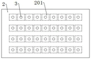
FIG. 2 is a schematic top view of the top plate of the present invention;
FIG. 3 is a schematic view, partly in half, of the interior of a thimble according to the invention;
FIG. 4 is a schematic view of a connection structure of the thimble and the top plate according to the present invention;
FIG. 5 is a schematic bottom view of the insert of the present invention;
FIG. 6 is a schematic view of the cooling head structure of the present invention;
fig. 7 is a schematic top view of the refrigeration plate of the present invention;
FIG. 8 is a schematic top view of the air deflection assembly of the present invention;
FIG. 9 is a schematic top view of an air guiding fan according to the present invention;
FIG. 10 is a schematic view of a connection structure of the braking plate and the air guiding fan.
In the figure: 1. a male die;
2. a top plate; 201. a cooling tank; 202. cooling the shell; 203. an air deflector; 204. a partition plate; 205. a bubble tube; 206. a drainage cover; 207. a refrigeration plate; 2031. a support plate; 2032. a wind guide fan; 2033. a brake plate; 2034. a restraining ball; 2035. a ratchet wheel; 2036. a screw rod;
3. a thimble; 4. an insert; 5. a feedback board; 6. a heat conducting rod; 601. and (6) cooling the head.
Detailed Description
The technical solutions in the embodiments of the present invention will be clearly and completely described below with reference to the drawings in the embodiments of the present invention, and it is obvious that the described embodiments are only a part of the embodiments of the present invention, and not all of the embodiments. All other embodiments, which can be derived by a person skilled in the art from the embodiments given herein without making any creative effort, shall fall within the protection scope of the present invention.
Referring to fig. 1 to 10, the present invention provides a technical solution: the utility model provides a high in production process cooling device for optical insert of stability, includes public mould 1, and cooling device for the optical insert includes roof 2, is provided with a plurality of thimble 3 on the roof 2, and thimble 3 inserts in public mould 1, and every thimble 3 is hollow structure, all is provided with mold insert 4 in the thimble 3, and mold insert 4 is made by beryllium copper material, all is provided with heat conduction stick 6 on every mold insert 4, and the one end of heat conduction stick 6 is fixed with coolant head 601, and coolant head 601 soaks in the coolant liquid.
The position that corresponds every thimble in roof 2 has all seted up cooling tank 201, install the cooling shell 202 that is C type shell structure in the cooling tank 201, cooling shell 202 cover is established on heat conduction stick 6, and cooling shell 202 covers on coolant head 601, the outside of cooling shell 202 is fixed with baffle 204, the space in cooling tank 201 is separated to baffle 204, the space above baffle 204 is the air flow space, the space below baffle 204 is the coolant liquid storage space, the coolant liquid holds in the coolant liquid storage space, baffle 204 below is fixed with drainage cover 206.
An air deflector 203 is fixed on the upper portion of a partition plate 204 on the outer side of a cooling shell 202, a bubble tube 205 is located below the air deflector 203, one end of the bubble tube 205 penetrates through the partition plate 204, one end of the bubble tube 205 is located in cooling liquid, a refrigerating plate 207 is fixed in the middle of the partition plate 204, the refrigerating plate 207 is located below the cooling shell 202 and a cooling head 601, the refrigerating plate 207 is soaked in the cooling liquid, the refrigerating plate 207 cools the cooling liquid, the refrigerating plate 207 is of a net-shaped structure and is electrically connected with a control system, the refrigerating plate 207 is composed of metal sheets and two semiconductors, and the two semiconductors absorb heat by using the Peltier effect.
The inner space of the thimble 3 is communicated with the cooling groove 201, one end of the heat conduction rod 6 is positioned in the cooling groove 201, the refrigerating plate 207 cools the heat conduction rod 6, and the air deflector 203 makes the air in the cooling groove 201 and the thimble 3 flow.
Set up annular air duct on the mold insert 4, air duct and 3 inner space intercommunications of thimble, the middle part position of mold insert 4 is inserted to the one end of heat conduction stick 6, has seted up the ventiduct in the heat conduction stick 6, ventiduct one end and air duct intercommunication, the ventiduct other end intercommunication cooling bath 201, has seted up the gas pocket on the heat conduction stick 6, the inside ventiduct of gas pocket intercommunication, the gas pocket is located the top of coolant liquid.
A wind guide fan 2032 is arranged in the wind guide plate 203, a mounting groove is formed in the wind guide plate 203, a support plate 2031 is fixed at the position of the mounting groove on the wind guide plate 203, a brake plate 2033 is arranged at the middle position of the support plate 2031, the brake plate 2033 is made of piezoelectric materials, the brake plate 2033 is electrically connected with a control system, the wind guide fan 2032 is positioned in the mounting groove, a ratchet 2035 is arranged on the wind guide fan 2032, a lead screw 2036 is arranged on the brake plate 2033, the lead screw 2036 penetrates through the ratchet 2035, and the lead screw 2036 is rotationally connected with the ratchet 2035;
the air deflector 203 has been seted up the spacing groove in the middle part position of mounting groove, all is provided with restriction ball 2034 on each flabellum of air-guiding fan 2032, and restriction ball 2034 is located the restriction inslot. The brake plate is made of piezoelectric materials, the brake plate is repeatedly bent under the control of the control system, the brake plate drives the screw rod to repeatedly move up and down, and the air guide fan rotates in one direction all the time due to the unidirectional rotation of the ratchet wheel, so that the rotation of the air guide fan is realized.
When the air guiding fan 2032 works, the air guiding fan 2032 extracts air in the thimble 3, so that cold air in the cooling shell 202 enters the ventilation channel due to negative pressure, the cold air takes away heat of the insert 4 when flowing through the ventilation channel, the air after temperature rise is extracted by the air guiding fan 2032 and is infused into the cooling liquid through the bubble tube 205, the air flowing in the ventilation channel is realized by the work of the air guiding fan 2032, and air cooling of the insert 4 is realized.
The cooling plate 207 cools the coolant under the control of the control system, the cooling head 601 is cooled by the coolant, the air guiding fan 2032 pumps the extracted hot air into the bubble tube 205, the bubble tube 205 guides the hot air into the coolant to cool the air in the coolant, meanwhile, the bubbles flow upward in the coolant to cause the coolant to tumble, the coolant in the whole cooling tank 201 flows, the coolant near the cooling head 601 flows, the low-temperature coolant at other positions flows near the cooling head 601 to cool the cooling head 601, thereby cooling the insert 4, the air is cooled by the coolant to form cold air, the cold air enters the air duct through the air holes, the insert 4 is cooled again through the air duct, the air passing through the coolant contains a large amount of moisture, and the heat absorption of the insert 4 can be improved, And (5) cooling effect.
The middle position of the insert 4 is fixed with a feedback plate 5, the feedback plate 5 is positioned above the heat conducting rod 6, the feedback plate 5 is also composed of a metal plate and two semiconductors, the two semiconductors monitor the temperature of the insert 4 by utilizing the seebeck effect, and the two semiconductors are electrically connected with a control system. The control system realizes temperature monitoring of each insert through temperature data fed back by the feedback plate, and controls the work of the refrigerating plate and the air guide fan, so that the temperature of each insert is independently controlled, and the condition that the local temperature in the male die is higher can be adapted.
The working principle of the invention is as follows:
when producing a plastic product, the temperature of the insert 4 is increased by the influence of the temperature of the plastic product, and when the plastic product is cooled and formed, the temperature of the insert 4 decreases the efficiency of forming the plastic product. During cooling forming, the control system controls the brake plate 2033 to work, so that the brake plate 2033 is repeatedly bent, the screw rod 2036 is driven by the brake plate 2033 to move up and down, the air guide fan 2032 is driven by the screw rod to rotate, the air guide fan 2032 extracts air in the thimble 3, cold air in the cooling shell 202 enters the ventilation channel due to negative pressure, when the cold air flows through the ventilation channel, heat of the insert 4 is taken away, the air after temperature rise is extracted by the air guide fan 2032 and is infused into the cooling liquid through the bubble tube 205, the air flow in the ventilation channel is realized by the work of the air guide fan 2032, and air cooling of the insert 4 is realized.
On the heat transfer of mold insert 4 arrived heat conduction stick 6, heat conduction stick 6 carried out the heat exchange through cooling head 601 and coolant liquid, and refrigeration board 207 carries out work under control system's control, cools down the coolant liquid.
The air guide fan 2032 pumps the extracted hot air into the bubble tube 205, the bubble tube 205 guides the hot air into the cooling liquid to cool the air in the cooling liquid, meanwhile, the bubbles flow upwards in the cooling liquid to make the cooling liquid turn over and flow the cooling liquid in the whole cooling tank 201, further make the cooling liquid near the cooling head 601 flow, make the low-temperature cooling liquid at other positions flow near the cooling head 601, and realize the cooling of the cooling head 601, thereby realizing the cooling of the insert 4, the air forms cold air after being cooled by the cooling liquid, and enters the air duct through the air hole, and realizes the secondary cooling of the insert 4 through the air duct, the air passing through the cooling liquid contains a large amount of moisture, and the heat absorption and cooling effects of the insert 4 can be improved.
The middle part position of mold insert 4 is fixed with feedback plate 5, and feedback plate 5 is located the top of heat conduction stick 6, and feedback plate 5 also comprises metal sheet and two kinds of semiconductor combination, and two kinds of semiconductor utilize seebeck effect to monitor the temperature of mold insert 4, and two kinds of semiconductor are connected with control system electricity. The control system realizes temperature monitoring of each insert through temperature data fed back by the feedback plate, and controls the work of the refrigerating plate and the air guide fan, so that the temperature of each insert is independently controlled, and the condition that the local temperature in the male mold is high can be adapted.
It is noted that, herein, relational terms such as first and second, and the like may be used solely to distinguish one entity or action from another entity or action without necessarily requiring or implying any actual such relationship or order between such entities or actions. Also, the terms "comprises," "comprising," or any other variation thereof, are intended to cover a non-exclusive inclusion, such that a process, method, article, or apparatus that comprises a list of elements does not include only those elements but may include other elements not expressly listed or inherent to such process, method, article, or apparatus.
Finally, it should be noted that: although the present invention has been described in detail with reference to the foregoing embodiments, it will be apparent to those skilled in the art that changes may be made in the embodiments and/or equivalents thereof without departing from the spirit and scope of the invention. Any modification, equivalent replacement, or improvement made within the spirit and principle of the present invention should be included in the protection scope of the present invention.
Claims (9)
1. The utility model provides an optical insert uses cooling device in production process that stability is high, includes public mould (1), its characterized in that: the cooling device for the optical insert comprises a top plate (2), wherein a plurality of ejector pins (3) are arranged on the top plate (2), the ejector pins (3) are inserted into a male die (1), each ejector pin (3) is of a hollow structure, inserts (4) are arranged in the ejector pins (3), and heat conducting rods (6) are arranged on each insert (4);
a cooling groove (201) is formed in the top plate (2) at a position corresponding to each ejector pin, a refrigerating plate (207) is arranged in the cooling groove (201), the inner space of each ejector pin (3) is communicated with the cooling groove (201), one end of the heat conducting rod (6) is located in the cooling groove (201), and the heat conducting rod (6) is cooled by the refrigerating plate (207);
An air deflector (203) is arranged in the cooling groove (201), and the air deflector (203) enables air in the cooling groove (201) and the ejector pin (3) to flow.
2. The high-stability cooling device for the optical insert in the production process according to claim 1, wherein: the mold insert is characterized in that an annular ventilating groove is formed in the mold insert (4) and is communicated with the inner space of the ejector pin (3), one end of the heat conducting rod (6) is arranged in the middle of the mold insert (4), a ventilating channel is formed in the heat conducting rod (6), one end of the ventilating channel is communicated with the ventilating groove, the other end of the ventilating channel is communicated with the cooling groove (201), and an air guide fan (2032) is arranged in the air guide plate (203).
3. The high-stability cooling device for the optical insert in the production process according to claim 2, wherein: an installation groove is formed in the air deflector (203), a support plate (2031) is arranged on the air deflector (203) at the position of the installation groove, a brake plate (2033) is arranged in the middle of the support plate (2031), the brake plate (2033) is made of piezoelectric materials, the brake plate (2033) is electrically connected with a control system, the air guiding fan (2032) is located in the installation groove, a ratchet wheel (2035) is arranged on the air guiding fan (2032), a lead screw (2036) is arranged on the brake plate (2033), the lead screw (2036) penetrates through the ratchet wheel (2035), and the lead screw (2036) is rotatably connected with the ratchet wheel (2035);
The wind deflector (203) is provided with a limiting groove in the middle of the mounting groove, each fan blade of the wind guiding fan (2032) is provided with a limiting ball (2034), and the limiting ball (2034) is located in the limiting groove.
4. The high-stability cooling device for the optical insert in the production process according to claim 2, wherein: the cooling device is characterized in that a bubble tube (205) is arranged below the air deflector (203) inside the cooling tank (201), cooling liquid is arranged in the cooling tank (201), one end of the bubble tube (205) is located in the cooling liquid, one end of the heat conducting rod (6) is provided with a cooling head (601), the cooling head (601) is soaked in the cooling liquid, an air hole is formed in the heat conducting rod (6) and communicated with an internal ventilation channel, the air hole is located above the cooling liquid, the refrigerating plate (207) is soaked in the cooling liquid, the refrigerating plate (207) is located below the cooling head (601), and the refrigerating plate (207) is connected with a control system.
5. The high-stability cooling device for the optical insert in the production process according to claim 2, wherein: the middle position of the insert (4) is provided with a feedback plate (5), the feedback plate (5) is positioned above the heat conducting rod (6), the feedback plate (5) is composed of a metal plate and two semiconductors, the two semiconductors monitor the temperature of the insert (4) by utilizing the Seebeck effect, and the two semiconductors are electrically connected with a control system.
6. The high-stability cooling device for the optical insert in the production process according to claim 5, wherein: be provided with cooling shell (202) that are C type shell structure in cooling tank (201), cooling shell (202) cover is established on heat conduction stick (6), and cooling shell (202) cover on cooling head (601), the outside of cooling shell (202) is provided with baffle (204), baffle (204) are separated the space in with cooling tank (201), and the space of baffle (204) top is the air flow space, and the space of baffle (204) below is coolant liquid storage space, the coolant liquid holds in coolant liquid storage space, bubble tube (205) run through baffle (204), refrigeration board (207) set up the middle part position at baffle (204), and refrigeration board (207) are located the below of cooling shell (202).
7. The high-stability cooling device for the optical insert in the production process according to claim 6, wherein: a drainage cover (206) is arranged below the clapboard (204).
8. The high-stability cooling device for the optical insert in the production process according to claim 6, wherein: the refrigerating plate (207) is a net-shaped refrigerating plate.
9. The high-stability cooling device for the optical insert in the production process according to claim 5, wherein: the insert (4) is made of beryllium copper material.
Priority Applications (1)
| Application Number | Priority Date | Filing Date | Title |
|---|---|---|---|
| CN202210206057.1A CN114701133B (en) | 2022-03-04 | 2022-03-04 | Cooling device for optical insert in production process with high stability |
Applications Claiming Priority (1)
| Application Number | Priority Date | Filing Date | Title |
|---|---|---|---|
| CN202210206057.1A CN114701133B (en) | 2022-03-04 | 2022-03-04 | Cooling device for optical insert in production process with high stability |
Publications (2)
| Publication Number | Publication Date |
|---|---|
| CN114701133A true CN114701133A (en) | 2022-07-05 |
| CN114701133B CN114701133B (en) | 2023-10-27 |
Family
ID=82167163
Family Applications (1)
| Application Number | Title | Priority Date | Filing Date |
|---|---|---|---|
| CN202210206057.1A Active CN114701133B (en) | 2022-03-04 | 2022-03-04 | Cooling device for optical insert in production process with high stability |
Country Status (1)
| Country | Link |
|---|---|
| CN (1) | CN114701133B (en) |
Citations (19)
| Publication number | Priority date | Publication date | Assignee | Title |
|---|---|---|---|---|
| JPH02274359A (en) * | 1989-04-18 | 1990-11-08 | Ube Ind Ltd | Die for forming wheel-shaped product and injection molding method |
| EP0947304A2 (en) * | 1998-03-31 | 1999-10-06 | Husky Injection Molding Systems Ltd. | Preform post-mold cooling method |
| JP2000210940A (en) * | 1999-01-25 | 2000-08-02 | Hitachi Metals Ltd | Mold cooling structure and mold cooling method |
| US6332770B1 (en) * | 1999-06-09 | 2001-12-25 | Husky Injection Molding Systems, Ltd. | Apparatus for localized preform cooling outside the mold |
| JP2006150638A (en) * | 2004-11-26 | 2006-06-15 | Hitachi Industrial Equipment Systems Co Ltd | Disk molding method and mold therefor |
| CN101489750A (en) * | 2006-07-26 | 2009-07-22 | 丰田自动车株式会社 | Cooling system for forming mold and method of cooling forming mold |
| KR101397086B1 (en) * | 2013-08-23 | 2014-05-19 | 주식회사 썬닉스 | Cooling apparatus for rack |
| CN103895199A (en) * | 2014-03-14 | 2014-07-02 | 东莞誉铭新工业有限公司 | Method for cooling molds by using gas |
| CN206170540U (en) * | 2016-11-18 | 2017-05-17 | 台州市黄岩宏特精工模具有限公司 | Injection mold and ejection mechanism thereof |
| CN209831102U (en) * | 2019-04-23 | 2019-12-24 | 湖南财经工业职业技术学院 | Electric spindle of numerical control machine tool |
| DE212020000260U1 (en) * | 2020-07-03 | 2020-12-02 | Suzhou Qianteng Precision Mould Co., Ltd. | An injection mold with quick heat dissipation |
| CN212385940U (en) * | 2020-05-11 | 2021-01-22 | 湖州博星科技有限公司 | Injection mold's refrigeration cooling device |
| CN213107711U (en) * | 2020-08-21 | 2021-05-04 | 昆山万威电子科技有限公司 | Cotton production of electrically conductive bubble is with mould that has quick cooling structure |
| CN213172086U (en) * | 2020-05-23 | 2021-05-11 | 崇义县鑫晨商砼有限公司 | Cooling tail exhaust fan for producing cement clinker by using industrial waste residues |
| CN213530751U (en) * | 2020-11-13 | 2021-06-25 | 苏州镁瑞电子科技有限公司 | Aluminum alloy casting device that cooling efficiency is high |
| CN214163838U (en) * | 2020-12-24 | 2021-09-10 | 常州华社塑料制品有限公司 | Quick cooling mold for dosing tank production |
| CN113597232A (en) * | 2021-09-27 | 2021-11-02 | 南通芯锂新能源科技有限公司 | Power pack of high security |
| CN215413288U (en) * | 2021-06-07 | 2022-01-04 | 苏州互友工业设备有限公司 | High-temperature gas quick cooler |
| CN215791366U (en) * | 2020-12-31 | 2022-02-11 | 威兹德模塑科技(苏州)有限公司 | Sunroof waterproof casing injection mold |
-
2022
- 2022-03-04 CN CN202210206057.1A patent/CN114701133B/en active Active
Patent Citations (19)
| Publication number | Priority date | Publication date | Assignee | Title |
|---|---|---|---|---|
| JPH02274359A (en) * | 1989-04-18 | 1990-11-08 | Ube Ind Ltd | Die for forming wheel-shaped product and injection molding method |
| EP0947304A2 (en) * | 1998-03-31 | 1999-10-06 | Husky Injection Molding Systems Ltd. | Preform post-mold cooling method |
| JP2000210940A (en) * | 1999-01-25 | 2000-08-02 | Hitachi Metals Ltd | Mold cooling structure and mold cooling method |
| US6332770B1 (en) * | 1999-06-09 | 2001-12-25 | Husky Injection Molding Systems, Ltd. | Apparatus for localized preform cooling outside the mold |
| JP2006150638A (en) * | 2004-11-26 | 2006-06-15 | Hitachi Industrial Equipment Systems Co Ltd | Disk molding method and mold therefor |
| CN101489750A (en) * | 2006-07-26 | 2009-07-22 | 丰田自动车株式会社 | Cooling system for forming mold and method of cooling forming mold |
| KR101397086B1 (en) * | 2013-08-23 | 2014-05-19 | 주식회사 썬닉스 | Cooling apparatus for rack |
| CN103895199A (en) * | 2014-03-14 | 2014-07-02 | 东莞誉铭新工业有限公司 | Method for cooling molds by using gas |
| CN206170540U (en) * | 2016-11-18 | 2017-05-17 | 台州市黄岩宏特精工模具有限公司 | Injection mold and ejection mechanism thereof |
| CN209831102U (en) * | 2019-04-23 | 2019-12-24 | 湖南财经工业职业技术学院 | Electric spindle of numerical control machine tool |
| CN212385940U (en) * | 2020-05-11 | 2021-01-22 | 湖州博星科技有限公司 | Injection mold's refrigeration cooling device |
| CN213172086U (en) * | 2020-05-23 | 2021-05-11 | 崇义县鑫晨商砼有限公司 | Cooling tail exhaust fan for producing cement clinker by using industrial waste residues |
| DE212020000260U1 (en) * | 2020-07-03 | 2020-12-02 | Suzhou Qianteng Precision Mould Co., Ltd. | An injection mold with quick heat dissipation |
| CN213107711U (en) * | 2020-08-21 | 2021-05-04 | 昆山万威电子科技有限公司 | Cotton production of electrically conductive bubble is with mould that has quick cooling structure |
| CN213530751U (en) * | 2020-11-13 | 2021-06-25 | 苏州镁瑞电子科技有限公司 | Aluminum alloy casting device that cooling efficiency is high |
| CN214163838U (en) * | 2020-12-24 | 2021-09-10 | 常州华社塑料制品有限公司 | Quick cooling mold for dosing tank production |
| CN215791366U (en) * | 2020-12-31 | 2022-02-11 | 威兹德模塑科技(苏州)有限公司 | Sunroof waterproof casing injection mold |
| CN215413288U (en) * | 2021-06-07 | 2022-01-04 | 苏州互友工业设备有限公司 | High-temperature gas quick cooler |
| CN113597232A (en) * | 2021-09-27 | 2021-11-02 | 南通芯锂新能源科技有限公司 | Power pack of high security |
Also Published As
| Publication number | Publication date |
|---|---|
| CN114701133B (en) | 2023-10-27 |
Similar Documents
| Publication | Publication Date | Title |
|---|---|---|
| CN201313376Y (en) | Adjustment mechanism of cooling device of tubular thin layer production equipment | |
| CN112497746A (en) | Printing forming chamber with local temperature control and 3D printer with printing forming chamber | |
| CN109484228A (en) | A kind of air-cooled circulatory system of direct-current charging post | |
| CN114643701B (en) | Blow molding die with cooling function for glove processing | |
| CN209666190U (en) | A kind of injection molding machine equipment for cooling die | |
| CN114701133A (en) | High-stability cooling device for optical insert in production process | |
| CN111497171A (en) | Plastic wire cooling and solidifying device for plastic granules | |
| CN107454809B (en) | Efficient micro-module data center | |
| CN109757085A (en) | Tapered gradual-enlargement type forced air cooling system | |
| CN213983851U (en) | Outdoor portable air-cooler | |
| CN210552854U (en) | Circuit device for allowing cooling water to enter and exit from one side of injection mold | |
| CN208197461U (en) | A kind of PLA biodegrade knife-fork-spoon molding machine | |
| CN208949320U (en) | A kind of high reliability cooling device | |
| CN111158098A (en) | Convection heat dissipation type optical cable distribution box based on Internet of things | |
| CN110076937A (en) | A kind of film face-plate molding die | |
| CN216968617U (en) | Quick refrigerated single wall bellows production line | |
| CN216152836U (en) | Air duct type annular heating mould for medical catheter | |
| CN215095521U (en) | EVA solar backboard film machine barrel oil heating and cooling device | |
| CN217834623U (en) | Plastic mould water cooling plant | |
| CN213035235U (en) | Injection mold processing cooling device | |
| CN218660243U (en) | Casing injection mold | |
| CN218366413U (en) | Cooling water tank for injection molding adhesive tape | |
| CN206905372U (en) | Produce the cooling tower of isoamyl alcohol polyoxyethylene ether | |
| CN220297632U (en) | Cooling device is used in plastic goods production | |
| CN211099957U (en) | Air blowing device for hot melt adhesive coating machine |
Legal Events
| Date | Code | Title | Description |
|---|---|---|---|
| PB01 | Publication | ||
| PB01 | Publication | ||
| SE01 | Entry into force of request for substantive examination | ||
| SE01 | Entry into force of request for substantive examination | ||
| GR01 | Patent grant | ||
| GR01 | Patent grant |