CN114683611A - Servo hole digging structure of corrugated paper carton and use method - Google Patents
Servo hole digging structure of corrugated paper carton and use method Download PDFInfo
- Publication number
- CN114683611A CN114683611A CN202210452654.2A CN202210452654A CN114683611A CN 114683611 A CN114683611 A CN 114683611A CN 202210452654 A CN202210452654 A CN 202210452654A CN 114683611 A CN114683611 A CN 114683611A
- Authority
- CN
- China
- Prior art keywords
- paper
- servo
- hole digging
- hole
- groups
- Prior art date
- Legal status (The legal status is an assumption and is not a legal conclusion. Google has not performed a legal analysis and makes no representation as to the accuracy of the status listed.)
- Pending
Links
Images


Classifications
-
- B—PERFORMING OPERATIONS; TRANSPORTING
- B31—MAKING ARTICLES OF PAPER, CARDBOARD OR MATERIAL WORKED IN A MANNER ANALOGOUS TO PAPER; WORKING PAPER, CARDBOARD OR MATERIAL WORKED IN A MANNER ANALOGOUS TO PAPER
- B31B—MAKING CONTAINERS OF PAPER, CARDBOARD OR MATERIAL WORKED IN A MANNER ANALOGOUS TO PAPER
- B31B50/00—Making rigid or semi-rigid containers, e.g. boxes or cartons
- B31B50/14—Cutting, e.g. perforating, punching, slitting or trimming
- B31B50/20—Cutting sheets or blanks
- B31B50/22—Notching; Trimming edges of flaps
-
- B—PERFORMING OPERATIONS; TRANSPORTING
- B31—MAKING ARTICLES OF PAPER, CARDBOARD OR MATERIAL WORKED IN A MANNER ANALOGOUS TO PAPER; WORKING PAPER, CARDBOARD OR MATERIAL WORKED IN A MANNER ANALOGOUS TO PAPER
- B31B—MAKING CONTAINERS OF PAPER, CARDBOARD OR MATERIAL WORKED IN A MANNER ANALOGOUS TO PAPER
- B31B50/00—Making rigid or semi-rigid containers, e.g. boxes or cartons
- B31B50/74—Auxiliary operations
Landscapes
- Making Paper Articles (AREA)
Abstract
The invention discloses a servo hole digging structure of a corrugated paper box and a using method thereof, and relates to the technical field of corrugated paper production. Including servo hole digger and set up in its one side and rather than the servo groover that matches, servo hole digger is including two sets of backup pads that the symmetry set up, set up the horizontal drive mechanism between two sets of backup pads, carry out the play paper pinch roller subassembly that removes and dig the hole subassembly and be used for the drive to dig the hole subassembly and dig the drive shaft in hole by the drive of horizontal drive mechanism, horizontal drive mechanism is including wearing to locate two sets of lead screws between two sets of backup pads. Through setting up servo hole digging machine and servo groover, compare in the conventional hole digging mode that adopts the cross cutting machine, the device with servo hole digging machine and servo groover linkage, the online integrality of solution all kinds of model cartons that can be better makes to reduce all kinds of circulation costs at the manufacturing process, and then reduced manufacturing cost, guaranteed production efficiency, accord with economic benefits, have wide application prospect.
Description
Technical Field
The invention relates to the technical field of corrugated paper production, in particular to a servo hole digging structure of a corrugated paper carton and a using method.
Background
The corrugated paper board is made into a corrugated paper box through die cutting, indentation, box nailing or box gluing. The corrugated case is a packaging product with the widest application, and the use amount is always the first of various packaging products. Comprises a calcium plastic corrugated case. For more than half a century, corrugated cartons gradually replace transport packaging containers such as wooden boxes and the like with excellent service performance and good processing performance, and become the leading force of transport packaging. It not only protects the goods, is convenient for storage and transportation, but also beautifies the goods and publicizes the goods. The corrugated case belongs to green environmental protection product, and it does benefit to the environmental protection, does benefit to the loading and unloading transportation.
Corrugated box is according to the user demand when production, need punch the operation sometimes, among the prior art, to the operation of punching of corrugated paper, generally go on through cross cutting machine, have and do not have special drilling equipment for corrugated paper after the fluting needs the manual work to be transported and punches the operation on cross cutting machine, and the process is loaded down with trivial details complicated and waste time and energy, can't satisfy the user demand.
Disclosure of Invention
In order to achieve the purpose, the invention provides the following technical scheme: a servo hole digging structure and a use method of a corrugated paper carton comprise a servo hole digging machine and a servo grooving machine which is arranged on one side of the servo hole digging machine and is matched with the servo hole digging machine, wherein the servo hole digging machine comprises two groups of supporting plates which are symmetrically arranged, a horizontal driving mechanism arranged between the two groups of supporting plates, a paper outlet pinch roller assembly and a hole digging assembly which are driven by the horizontal driving mechanism to move, and a driving shaft used for driving the hole digging assembly to dig holes;
the horizontal driving mechanism comprises two groups of screw rods which are arranged between two groups of supporting plates in a penetrating manner, wherein two ends of one group of screw rods are provided with a first servo motor;
the paper outlet pinch roller assembly comprises a connecting plate sleeved on one group of lead screws and a linear bearing arranged on one side of the connecting plate;
the hole digging assembly comprises a movable plate sleeved on the other group of screw rods and a cutting die driving wheel arranged on one side of the movable plate, the cutting die driving wheel is positioned above the linear bearing, and a hole digging blade seat is arranged on the cutting die driving wheel;
the inside of fly leaf is provided with the drive shaft of wearing to locate between two sets of backup pads, the one end of drive shaft is provided with and is used for driving the rotatory servo motor two of drive shaft.
As a preferable technical scheme of the invention, two ends of the screw rod are respectively provided with a first gear, one side of the support plate is provided with a second gear, the first gear and the second gear are in transmission connection through a belt, and one side of the first servo motor is provided with an installation plate, one end of the installation plate is fixedly connected with one side of the support plate.
As a preferred technical scheme of the present invention, two sets of upper slide rails and a lower slide rail located below the two sets of upper slide rails are fixedly disposed between the two sets of support plates, wherein one set of upper slide rails is provided with a center zero position sensor, and a first limit sensor and a second limit sensor respectively located at two sides of the center zero position sensor.
As a preferred technical scheme, a paper outlet lower rubber mat is arranged on the linear bearing, a paper outlet protective plate is arranged at one end of the top of the connecting plate and is arranged in an L shape, a bending part is arranged at one end of the paper outlet protective plate, and a first guide wheel positioned at one side of the linear bearing is arranged at one side of the connecting plate.
According to a preferable technical scheme of the invention, paper feeding correlation sensors are arranged on one sides of the connecting plate and the movable plate, the two paper feeding correlation sensors are arranged oppositely, a fixed plate is arranged on one side of the movable plate, and at least two guide wheels II which are positioned above the guide wheels I are movably arranged on one side of the movable plate.
As a preferred technical scheme of the invention, one end of the linear bearing is provided with a gear III, the driving shaft is provided with a key groove, and a key pin with one end extending into the key groove is arranged in the cutting die driving wheel so as to realize transmission between the cutting die driving wheel and the driving shaft;
the driving shaft is provided with an induction sheet, and one side of one group of the supporting plates is provided with a zero position inductor of the hole digging handle cutting die positioned on one side of the induction sheet.
As a preferred technical scheme of the present invention, a sliding plate is disposed at the top of the movable plate, the top of the sliding plate is slidably connected to the bottom of the upper sliding rail, a supporting rod is disposed at the top of the sliding plate and extends to one side of one of the upper sliding rails, and a main shaft movably disposed between the two sets of supporting plates is disposed inside the linear bearing.
As a preferred technical scheme of the invention, the lower slide rail comprises a support rod fixedly arranged between two groups of support plates, the top of the support rod is movably provided with at least one slide seat, the top of the slide seat is provided with a connecting seat, and one end of the connecting seat is fixedly connected with one end of a connecting plate.
As a preferred technical scheme of the invention, the number of the paper-out pinch roller assemblies and the number of the hole-digging assemblies are not less than two, the two paper-out pinch roller assemblies are symmetrically arranged, the two hole-digging assemblies are symmetrically arranged, and the servo motor II is arranged on one side of one group of supporting plates through a fixed bracket;
mutual opposite screw thread, two have been seted up at the both ends of perpendicular bisector on the surface of lead screw the internal thread that meshes mutually with the lead screw junction is seted up respectively to the inside of connecting plate and fly leaf, the activity is provided with quantity between the backup pad and is no less than two paper feed compression rollers, two the paper feed compression roller is placed from top to bottom.
A use method of a servo hole digging structure of a corrugated paper carton comprises the following steps:
s1, position calibration, namely starting a servo motor II to drive a cutting die driving wheel to rotate, and installing a hole digging cutter on a hole digging blade seat when a driving shaft drives an induction blade to rotate to be inducted by a hole digging lifting handle cutting die zero position inductor;
s2, confirming the thickness of the paper, wherein the distance between the two paper feeding press rollers is matched with the thickness of the paper, and conveying the paper to the paper feeding press rollers through a grooving machine;
s3, confirming the hole digging position, sensing the conveyed paper by the paper feeding correlation sensor, starting the servo motor II to drive the hole digging cutter to rotate, confirming the hole digging accuracy of the paper, and then performing hole digging operation;
and S4, discharging and guiding, wherein the paper after hole digging is guided out through a paper discharging lower rubber mat, a paper discharging guard plate, a first guide wheel and a second guide wheel on the linear bearing.
Compared with the prior art, the invention provides a servo hole digging structure of a corrugated paper carton and a using method thereof, and the servo hole digging structure has the following beneficial effects:
according to the servo hole digging structure and the using method of the corrugated paper carton, the servo hole digging machine and the servo grooving machine are arranged, compared with a conventional hole digging mode of a die cutting machine, the servo hole digging machine is linked with the servo grooving machine by the servo hole digging machine, and the problem of line integrity of various types of cartons can be better solved, so that various circulation costs in the manufacturing process are reduced, the production cost is reduced, the production efficiency is guaranteed, economic benefits are met, and the servo hole digging structure and the servo grooving machine have wide application prospects.
Drawings
Fig. 1 is a schematic structural view of a servo hole digging structure of a corrugated paper carton and a use method thereof according to the present invention;
fig. 2 is a schematic structural view of a servo hole digging machine of a corrugated paper carton servo hole digging structure and a use method thereof according to the present invention;
FIG. 3 is an enlarged view of the structure at A in FIG. 2;
FIG. 4 is a rear view of a corrugated cardboard box servo hole digging structure and a method of use thereof according to the present invention;
FIG. 5 is an enlarged view of the structure at A in FIG. 4;
FIG. 6 is a front view of a servo hole digging machine structure of a corrugated paper carton and a method of use according to the present invention;
fig. 7 is a schematic structural view of a connecting plate and a movable plate of a corrugated paper carton servo hole digging structure and a use method thereof according to the present invention;
FIG. 8 is an enlarged view of the structure at A in FIG. 7;
fig. 9 is a schematic structural view of a connecting plate and a movable plate of a corrugated paper carton servo hole digging structure and a use method thereof according to the present invention;
fig. 10 is a rear view of a connecting plate and a movable plate structure of a corrugated paper carton servo hole digging structure and a use method thereof according to the present invention;
fig. 11 is a side view of the connection plate and the movable plate structure of the corrugated paper box servo hole-digging structure and the use method thereof according to the present invention;
fig. 12 is a flow chart illustrating a servo hole digging structure of a corrugated paper box and a use method thereof according to the present invention.
In the figure: 1. a servo hole digging machine; 11. a support plate; 111. an upper slide rail; 112. a center zero position sensor; 113. a first limit inductor; 114. a second limit inductor; 115. a hole digging handle cutting die zero position sensor; 12. a horizontal driving mechanism; 121. a lead screw; 122. a first gear; 123. a second gear; 124. a first servo motor; 125. mounting a plate; 13. a paper-out pressing wheel component; 131. a connecting plate; 132. a linear bearing; 133. a paper outlet guard plate; 134. a first guide wheel; 135. a third gear; 14. digging a hole assembly; 141. a movable plate; 142. a cutting die driving wheel; 143. a fixing plate; 144. a second guide wheel; 145. digging a hole on the blade seat; 146. a slide plate; 147. a strut; 15. a paper feed correlation sensor; 16. a main shaft; 17. a drive shaft; 171. a servo motor II; 172. an induction sheet; 18. a lower slide rail; 181. a support bar; 182. a slide base; 183. a connecting seat; 19. a paper feed press roller; 2. provided is a servo grooving machine.
Detailed Description
The technical solutions in the embodiments of the present invention will be clearly and completely described below with reference to the drawings in the embodiments of the present invention, and it is obvious that the described embodiments are only a part of the embodiments of the present invention, and not all of the embodiments. All other embodiments, which can be derived by a person skilled in the art from the embodiments given herein without making any creative effort, shall fall within the protection scope of the present invention.
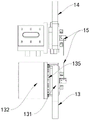
Referring to fig. 1-12, a servo hole digging structure and a using method for a corrugated paper carton include a servo hole digging machine 1 and a servo grooving machine 2 disposed at one side of the servo hole digging machine and matched with the servo hole digging machine, where the servo hole digging machine 1 includes two sets of support plates 11 symmetrically disposed, a horizontal driving mechanism 12 disposed between the two sets of support plates 11, a paper output pinch roller assembly 13 and a hole digging assembly 14 driven by the horizontal driving mechanism 12 to move, and a driving shaft 17 for driving the hole digging assembly 14 to dig holes.
The horizontal driving mechanism 12 comprises two groups of screw rods penetrating between two groups of supporting plates 11, wherein two ends of one group of screw rods are provided with a first servo motor 124.
The paper discharging pinch roller assembly 13 includes a connection plate 131 sleeved on one set of the lead screws 121 and a linear bearing 132 disposed on one side of the connection plate 131.
The hole digging assembly 14 includes a movable plate 141 sleeved on the other set of screw rods 121 and a cutting die driving wheel 142 disposed on one side of the movable plate 141, the cutting die driving wheel 142 is located above the linear bearing 132, and a hole digging blade seat 145 is disposed on the cutting die driving wheel 142.
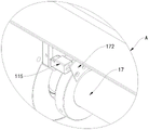
The movable plate 141 is internally provided with a driving shaft 17 penetrating between the two sets of supporting plates 11, and one end of the driving shaft 17 is provided with a second servo motor 171 for driving the driving shaft 17 to rotate.
As a specific technical scheme of this embodiment, all be provided with gear 122 on the both ends of lead screw 121, one side of backup pad 11 is provided with gear two 123, be connected through belt transmission between gear 122 and the gear two 123, one side of servo motor 124 is provided with one end and backup pad 11 one side fixed connection's mounting panel 125, and mounting panel 125 is used for supporting servo motor 124, has guaranteed the stability of servo motor 124, starts servo motor 124, and servo motor 124 drives gear 122 and rotates, and gear 122 drives gear two 123 through the belt and rotates, and the setting of gear two 123 is used for increasing the tension of belt, has guaranteed the stability of belt.
As a specific technical solution of this embodiment, two sets of upper slide rails 111 and a lower slide rail 18 located below the two sets of upper slide rails 111 are fixedly disposed between the two sets of support plates 11, wherein one set of the upper slide rails 111 is provided with a center zero point position sensor 112 and a first limit sensor 113 and a second limit sensor 114 respectively located at two sides of the center zero point position sensor 112, and the upper slide rails 111 are disposed for installing the center zero point position sensor 112, the first limit sensor 113 and the second limit sensor.
As a concrete technical scheme of this embodiment, be provided with rubber mat under the play paper on linear bearing 132, the top one end of connecting plate 131 is provided with play paper backplate 133, play paper backplate 133 is the setting of L shape, the one end of going out paper backplate 133 is provided with the portion of bending, one side of connecting plate 131 is provided with leading wheel 134 that is located linear bearing 132 one side, and the setting of rubber mat has increased the frictional force between linear bearing 132 and the paper under the play paper for paper transportation process is more stable, smooth and easy, goes out paper backplate 133's setting for support the paper of carrying, the setting of the portion of bending, the condition of taking place the conflict when having avoided the one end of play paper backplate 133 and paper contact.
As a specific technical solution of this embodiment, the connection plate 131 and one side of the movable plate 141 are both provided with the paper feeding correlation sensor 15, the two paper feeding correlation sensors 15 are arranged oppositely, one side of the movable plate 141 is provided with the fixed plate 143, one side of the movable plate 141 is movably provided with the guide wheels two 144 which are located above the guide wheels one 134 and are not less than two in number, when the paper moves between the connection plate 131 and the movable plate 141, the paper feeding correlation sensor 15 is blocked, so as to determine whether the paper is in place, the guide wheels one 134 and the guide wheels two 144 guide the paper whose hole is dug, and the blanking efficiency after the hole is dug of the paper is ensured.
As a specific technical solution of this embodiment, one end of the linear bearing 132 is provided with a gear three 135, the driving shaft 17 is provided with a key slot, the cutting die driving wheel 142 is provided with a key pin, one end of the key pin extends into the key slot, so as to realize transmission between the cutting die driving wheel 142 and the driving shaft 17, the driving shaft 17 is provided with a sensing piece 172, one side of one group of the supporting plates 11 is provided with a hole digging handle cutting die zero position sensor 115 located at one side of the sensing piece 172, and the key slot is matched with the key pin, so that the driving shaft 17 drives the cutting die driving wheel 142 to rotate, and meanwhile, horizontal sliding of the cutting die driving wheel 142 on the driving shaft 17 is not affected, and the sensing piece 172 is matched with the hole digging handle cutting die positioning sensor, thereby facilitating determination of the position of the hole digging blade seat 145.
As a specific technical solution of this embodiment, a sliding plate 146 is disposed at the top of the movable plate 141, the top of the sliding plate 146 is slidably connected to the bottom of the upper sliding rail 111, a supporting rod 147 is disposed at the top of the sliding plate 146 and extends to one side of one of the sets of upper sliding rails 111, a main shaft 16 movably disposed between the two sets of supporting plates 11 is disposed inside the linear bearing 132, and the supporting rod 147 is disposed to cooperate with the center zero point position sensor 112, the first limit sensor 113 and the second limit sensor 114 to determine a left-right movement distance between the movable plate 141 and the connecting plate 131, so that the moving positions of the connecting plate 131 and the movable plate 141 are more accurate.
As a specific technical solution of this embodiment, the lower slide rail 18 includes a support rod 181 fixedly disposed between two sets of support plates 11, the top activity of the support rod 181 is provided with a slide seat 182 that is not less than one in number, the top of the slide seat 182 is provided with a connecting seat 183, one end of the connecting seat 183 is fixedly connected with one end of a connecting plate 131, the lower slide rail 18 is matched with the upper slide rail 111, the connecting plate 131 drives the slide seat 182 to slide on the support rod 181 when moving, and meanwhile, the sliding plate 146 slides on the upper slide rail 111, so as to limit the axial rotation of the connecting plate 131 and the movable plate 141, and when the lead screw 121 rotates, the connecting plate 131 and the movable plate 141 can only move horizontally and cannot rotate.
As a specific technical solution of this embodiment, the number of the paper discharging pinch roller assemblies 13 and the hole digging assemblies 14 is not less than two, two sets of the paper discharging pinch roller assemblies 13 are symmetrically arranged, two hole digging assemblies 14 are symmetrically arranged, the second servo motor 171 is arranged on one side of one set of the supporting plate 11 through a fixing bracket, opposite threads are arranged on two ends of the surface of the lead screw 121 with respect to a perpendicular bisector, internal threads meshed with the joint of the lead screw 121 are respectively arranged inside the two connecting plates 131 and the movable plate 141, at least two paper feeding compression rollers 19 are movably arranged between the supporting plates 11, the two paper feeding compression rollers 19 are arranged up and down, the paper feeding compression rollers 19 are used for guiding paper received from the servo grooving machine 2, opposite threads are arranged on two ends of the surface of the lead screw 121 with respect to a perpendicular bisector, so that the two connecting plates 131 move towards or away from each other along with the rotation of the lead screw 121, the two movable plates 141 are also the same.
A use method of a servo hole digging structure of a corrugated paper carton comprises the following steps:
s1, position calibration, namely, starting the servo motor II 171 to drive the cutting die driving wheel 142 to rotate, and when the driving shaft 17 drives the sensing piece 172 to rotate to be sensed by the hole digging handle cutting die zero position sensor 115, installing a hole digging cutter on the hole digging blade seat 145;
s2, confirming the thickness of the paper, wherein the distance between the two paper feeding pressure rollers 19 is matched with the thickness of the paper, and conveying the paper to the paper feeding pressure rollers 19 through a grooving machine;
s3, hole digging position confirmation, wherein the paper feeding correlation sensor 15 senses conveyed paper, the servo motor II 171 is started to drive the hole digging cutter to rotate, the servo motor I124 is started to drive the screw rod to rotate, the connecting plates 131 and the movable plates 141 are horizontal along with the screw rod, and are provided with two sections of threads opposite to those on the screw rod 121, so that the two connecting plates 131 run in the opposite direction or in the opposite direction along with the rotation of the screw rod 121, and the two movable plates 141 run synchronously with the two connecting plates 131, so that the position of the hole digging cutter on the paper is determined, the hole digging accuracy of the paper is confirmed, and the hole digging operation can be performed;
and S4, discharging and guiding, wherein the paper after hole digging is guided out through the paper discharging lower rubber mat on the linear bearing 132, the paper discharging guard plate 133, the first guide wheel 134 and the second guide wheel 144.
In conclusion, according to the servo hole digging structure and the use method of the corrugated paper carton, by arranging the servo hole digging machine 1 and the servo grooving machine 2, compared with a conventional hole digging mode adopting a die cutting machine, the servo hole digging machine 1 and the servo grooving machine 2 are linked by the servo hole digging machine and the servo grooving machine, the problem of line connection integrity of various types of cartons can be better solved, so that various circulation costs in the manufacturing process are reduced, the production cost is further reduced, the production efficiency is guaranteed, the servo hole digging structure and the use method of the servo hole digging machine accord with economic benefits, and the servo hole digging structure and the servo grooving machine have wide application prospects.
It should be noted that, in this document, terms such as "comprises," "comprising," or any other variation thereof, are intended to cover a non-exclusive inclusion, such that a process, method, article, or apparatus that comprises a list of elements does not include only those elements but may include other elements not expressly listed or inherent to such process, method, article, or apparatus. Without further limitation, an element defined by the phrase "comprising an … …" does not exclude the presence of other identical elements in a process, method, article, or apparatus that comprises the element.
Although embodiments of the present invention have been shown and described, it will be appreciated by those skilled in the art that changes, modifications, substitutions and alterations can be made in these embodiments without departing from the principles and spirit of the invention, the scope of which is defined in the appended claims and their equivalents.
Claims (10)
1. The utility model provides a servo hole structure of digging of corrugated paper carton, includes servo hole machine (1) of digging and set up in its one side and rather than supporting servo groover (2), its characterized in that: the servo hole digging machine (1) comprises two groups of supporting plates (11) which are symmetrically arranged, a horizontal driving mechanism (12) arranged between the two groups of supporting plates (11), a paper discharging pinch roller assembly (13) and a hole digging assembly (14) which are driven by the horizontal driving mechanism (12) to move, and a driving shaft (17) for driving the hole digging assembly (14) to dig holes;
the horizontal driving mechanism (12) comprises two groups of screw rods which are arranged between two groups of supporting plates (11) in a penetrating way, and two ends of one group of screw rods are provided with a first servo motor (124);
the paper discharging pinch roller assembly (13) comprises a connecting plate (131) sleeved on one group of lead screws (121) and a linear bearing (132) arranged on one side of the connecting plate (131);
the hole digging assembly (14) comprises a movable plate (141) sleeved on the other group of screw rods (121) and a cutting die driving wheel (142) arranged on one side of the movable plate (141), the cutting die driving wheel (142) is positioned above the linear bearing (132), and a hole digging blade seat (145) is arranged on the cutting die driving wheel (142);
the driving shaft (17) is arranged between the two groups of supporting plates (11) in a penetrating mode, and a second servo motor (171) used for driving the driving shaft (17) to rotate is arranged at one end of the driving shaft (17).
2. The servo hole digging structure for corrugated paper cartons as claimed in claim 1, wherein: all be provided with gear (122) on the both ends of lead screw (121), one side of backup pad (11) is provided with gear two (123), be connected through belt transmission between gear one (122) and gear two (123), one side of servo motor one (124) is provided with one end and backup pad (11) one side fixed connection's mounting panel (125).
3. The servo hole digging structure for corrugated paper cartons as claimed in claim 1, wherein: two groups of upper slide rails (111) and lower slide rails (18) positioned below the two groups of upper slide rails (111) are fixedly arranged between the two groups of supporting plates (11), wherein a center zero position sensor (112), a first limit sensor (113) and a second limit sensor (114) which are respectively positioned at two sides of the center zero position sensor (112) are arranged on one group of upper slide rails (111).
4. The servo hole digging structure for corrugated paper cartons as claimed in claim 1, wherein: be provided with out the cushion under the paper on linear bearing (132), the top one end of connecting plate (131) is provided with out paper backplate (133), it sets up to go out paper backplate (133) to be L shape, the one end of going out paper backplate (133) is provided with the portion of bending, one side of connecting plate (131) is provided with leading wheel one (134) that are located linear bearing (132) one side.
5. The servo hole digging structure for corrugated paper cartons as claimed in claim 1, wherein: one side of connecting plate (131) and fly leaf (141) all is provided with paper feed correlation inductor (15), two paper feed correlation inductor (15) are relative setting, one side of fly leaf (141) is provided with fixed plate (143), one side activity of fly leaf (141) is provided with and is located leading wheel one (134) top and quantity is no less than two leading wheel two (144).
6. The servo hole digging structure for corrugated paper cartons as claimed in claim 1, wherein: one end of the linear bearing (132) is provided with a gear III (135), the driving shaft (17) is provided with a key groove, and a key pin with one end extending to the inside of the key groove is arranged inside the cutting die driving wheel (142) so as to realize transmission between the cutting die driving wheel (142) and the driving shaft (17);
the driving shaft (17) is provided with an induction sheet (172), and one side of one group of the supporting plates (11) is provided with a zero position inductor (115) of the hole digging handle cutting die positioned on one side of the induction sheet (172).
7. The servo hole digging structure for corrugated paper cartons as claimed in claim 3, wherein: the top of fly leaf (141) is provided with slide (146), the top and the bottom sliding connection of last slide rail (111) of slide (146), the top of slide (146) is provided with top and extends to branch (147) of one side of one of them group of last slide rail (111), the inside of linear bearing (132) is provided with the activity and wears to locate main shaft (16) between two sets of backup pads (11).
8. The servo hole digging structure for corrugated paper cartons as claimed in claim 7, wherein: the lower sliding rail (18) comprises supporting rods (181) fixedly arranged between two groups of supporting plates (11), the top of each supporting rod (181) is movably provided with at least one sliding seat (182), the top of each sliding seat (182) is provided with a connecting seat (183), and one end of each connecting seat (183) is fixedly connected with one end of each connecting plate (131).
9. The servo hole digging structure for corrugated paper cartons as claimed in claim 1, wherein: the number of the paper discharging pinch roller assemblies (13) and the number of the hole digging assemblies (14) are not less than two, the two groups of paper discharging pinch roller assemblies (13) are symmetrically arranged, the two hole digging assemblies (14) are symmetrically arranged, and the second servo motor (171) is arranged on one side of one group of supporting plates (11) through a fixing support;
the surface of the lead screw (121) is provided with opposite threads at two ends of a perpendicular bisector, internal threads meshed with the connection part of the lead screw (121) are respectively arranged in the connecting plate (131) and the movable plate (141), at least two paper feeding press rollers (19) are movably arranged between the supporting plates (11), and the two paper feeding press rollers (19) are arranged up and down.
10. A method of using the corrugated cardboard box servo hole-punching structure of any of claims 1 to 9, comprising the steps of:
s1, position calibration, namely, starting a servo motor II (171) to drive a cutting die driving wheel (142) to rotate, and when a driving shaft (17) drives an induction sheet (172) to rotate to be inducted by a hole digging handle cutting die zero position inductor (115), installing a hole digging cutter on a hole digging cutter blade seat (145);
s2, confirming the thickness of the paper, wherein the distance between the two paper feeding pressing rollers (19) is matched with the thickness of the paper, and conveying the paper to the paper feeding pressing rollers (19) through a grooving machine;
s3, confirming hole digging positions, sensing the conveyed paper by a paper feeding opposite-jet sensor (15), starting a servo motor II (171) to drive a hole digging cutter to rotate, confirming the hole digging accuracy of the paper, and then performing hole digging operation;
and S4, discharging and guiding, wherein the paper after hole digging is guided out through a paper discharging lower rubber mat on the linear bearing (132), a paper discharging protective plate (133), a first guide wheel (134) and a second guide wheel (144).
Priority Applications (1)
| Application Number | Priority Date | Filing Date | Title |
|---|---|---|---|
| CN202210452654.2A CN114683611A (en) | 2022-04-27 | 2022-04-27 | Servo hole digging structure of corrugated paper carton and use method |
Applications Claiming Priority (1)
| Application Number | Priority Date | Filing Date | Title |
|---|---|---|---|
| CN202210452654.2A CN114683611A (en) | 2022-04-27 | 2022-04-27 | Servo hole digging structure of corrugated paper carton and use method |
Publications (1)
| Publication Number | Publication Date |
|---|---|
| CN114683611A true CN114683611A (en) | 2022-07-01 |
Family
ID=82145642
Family Applications (1)
| Application Number | Title | Priority Date | Filing Date |
|---|---|---|---|
| CN202210452654.2A Pending CN114683611A (en) | 2022-04-27 | 2022-04-27 | Servo hole digging structure of corrugated paper carton and use method |
Country Status (1)
| Country | Link |
|---|---|
| CN (1) | CN114683611A (en) |
-
2022
- 2022-04-27 CN CN202210452654.2A patent/CN114683611A/en active Pending
Similar Documents
| Publication | Publication Date | Title |
|---|---|---|
| CN213356014U (en) | Deviation rectifying and aligning equipment for corrugated case | |
| CN209999281U (en) | corrugated board cutting and separating device | |
| US5275075A (en) | Adjustable triple wall fold apparatus and method | |
| CN217574258U (en) | Servo hole digging structure for corrugated paper carton | |
| CN114683611A (en) | Servo hole digging structure of corrugated paper carton and use method | |
| CN218701643U (en) | Punching mechanism for carton production | |
| CN211222253U (en) | Automatic indentation mechanism of carton production usefulness | |
| CN210190738U (en) | Automatic corrugated board cutting machine | |
| US20020069993A1 (en) | Installation for the manufacture of a multi-layer material and material thus obtained | |
| CN115107316A (en) | Carton processing equipment capable of automatically stacking and processing method thereof | |
| CN214522254U (en) | Servo transverse wire pressing structure of corrugated paper carton | |
| CN113353698A (en) | Fluted plate machine | |
| CN111016283B (en) | High-efficient area handle carton production system of environmental protection | |
| CN216183239U (en) | Novel machine for producing single-sided corrugated paper by circular pressing and die cutting | |
| CN112998340A (en) | Boot sleeve machine | |
| CN2830058Y (en) | Stretching dryer of honeycomb sandwich board | |
| CN216233215U (en) | Cardboard tectorial membrane device | |
| CN2183875Y (en) | Paper feeding mechanism of corrugated board printing and cutting machine | |
| CN214056605U (en) | Device is tailor to high strength antidetonation packing carton | |
| CN213445419U (en) | High-speed automatic coiled material crosscut machine | |
| CN215557806U (en) | Splitting machine | |
| CN220945522U (en) | Multi-station splitting machine for pulp layer paper production | |
| CN110626849A (en) | Paper receiving mechanism | |
| CN215755574U (en) | Edge cutting device suitable for printing paper | |
| CN213922682U (en) | Teflon belt automatic deviation rectifying mechanism of double-belt laminating machine production line |
Legal Events
| Date | Code | Title | Description |
|---|---|---|---|
| PB01 | Publication | ||
| PB01 | Publication | ||
| SE01 | Entry into force of request for substantive examination | ||
| SE01 | Entry into force of request for substantive examination | ||
| CB02 | Change of applicant information |
Address after: No. 101, No. 7, Fengshun Road, Tongxin Community, Baolong Street, Longgang District, Shenzhen City, Guangdong Province, 518000 Applicant after: Shenzhen Wande Digital Technology Co.,Ltd. Address before: 518000 No.5 Fumin Road, Fumin Industrial Zone, Pinghu street, Longgang District, Shenzhen City, Guangdong Province Applicant before: SHENZHEN WONDER PRINTING SYSTEM Co.,Ltd. |
|
| CB02 | Change of applicant information |