CN114665194A - Pipeline assembly, cooling device, battery and electric device - Google Patents
Pipeline assembly, cooling device, battery and electric device Download PDFInfo
- Publication number
- CN114665194A CN114665194A CN202210546663.8A CN202210546663A CN114665194A CN 114665194 A CN114665194 A CN 114665194A CN 202210546663 A CN202210546663 A CN 202210546663A CN 114665194 A CN114665194 A CN 114665194A
- Authority
- CN
- China
- Prior art keywords
- pipeline
- sub
- channel
- battery
- section
- Prior art date
- Legal status (The legal status is an assumption and is not a legal conclusion. Google has not performed a legal analysis and makes no representation as to the accuracy of the status listed.)
- Granted
Links
Images


Classifications
-
- H—ELECTRICITY
- H01—ELECTRIC ELEMENTS
- H01M—PROCESSES OR MEANS, e.g. BATTERIES, FOR THE DIRECT CONVERSION OF CHEMICAL ENERGY INTO ELECTRICAL ENERGY
- H01M10/00—Secondary cells; Manufacture thereof
- H01M10/60—Heating or cooling; Temperature control
- H01M10/61—Types of temperature control
- H01M10/613—Cooling or keeping cold
-
- H—ELECTRICITY
- H01—ELECTRIC ELEMENTS
- H01M—PROCESSES OR MEANS, e.g. BATTERIES, FOR THE DIRECT CONVERSION OF CHEMICAL ENERGY INTO ELECTRICAL ENERGY
- H01M10/00—Secondary cells; Manufacture thereof
- H01M10/60—Heating or cooling; Temperature control
- H01M10/62—Heating or cooling; Temperature control specially adapted for specific applications
- H01M10/625—Vehicles
-
- H—ELECTRICITY
- H01—ELECTRIC ELEMENTS
- H01M—PROCESSES OR MEANS, e.g. BATTERIES, FOR THE DIRECT CONVERSION OF CHEMICAL ENERGY INTO ELECTRICAL ENERGY
- H01M10/00—Secondary cells; Manufacture thereof
- H01M10/60—Heating or cooling; Temperature control
- H01M10/65—Means for temperature control structurally associated with the cells
- H01M10/655—Solid structures for heat exchange or heat conduction
- H01M10/6556—Solid parts with flow channel passages or pipes for heat exchange
-
- H—ELECTRICITY
- H01—ELECTRIC ELEMENTS
- H01M—PROCESSES OR MEANS, e.g. BATTERIES, FOR THE DIRECT CONVERSION OF CHEMICAL ENERGY INTO ELECTRICAL ENERGY
- H01M10/00—Secondary cells; Manufacture thereof
- H01M10/60—Heating or cooling; Temperature control
- H01M10/65—Means for temperature control structurally associated with the cells
- H01M10/656—Means for temperature control structurally associated with the cells characterised by the type of heat-exchange fluid
- H01M10/6561—Gases
-
- H—ELECTRICITY
- H01—ELECTRIC ELEMENTS
- H01M—PROCESSES OR MEANS, e.g. BATTERIES, FOR THE DIRECT CONVERSION OF CHEMICAL ENERGY INTO ELECTRICAL ENERGY
- H01M10/00—Secondary cells; Manufacture thereof
- H01M10/60—Heating or cooling; Temperature control
- H01M10/65—Means for temperature control structurally associated with the cells
- H01M10/656—Means for temperature control structurally associated with the cells characterised by the type of heat-exchange fluid
- H01M10/6567—Liquids
- H01M10/6568—Liquids characterised by flow circuits, e.g. loops, located externally to the cells or cell casings
-
- Y—GENERAL TAGGING OF NEW TECHNOLOGICAL DEVELOPMENTS; GENERAL TAGGING OF CROSS-SECTIONAL TECHNOLOGIES SPANNING OVER SEVERAL SECTIONS OF THE IPC; TECHNICAL SUBJECTS COVERED BY FORMER USPC CROSS-REFERENCE ART COLLECTIONS [XRACs] AND DIGESTS
- Y02—TECHNOLOGIES OR APPLICATIONS FOR MITIGATION OR ADAPTATION AGAINST CLIMATE CHANGE
- Y02E—REDUCTION OF GREENHOUSE GAS [GHG] EMISSIONS, RELATED TO ENERGY GENERATION, TRANSMISSION OR DISTRIBUTION
- Y02E60/00—Enabling technologies; Technologies with a potential or indirect contribution to GHG emissions mitigation
- Y02E60/10—Energy storage using batteries
Landscapes
- Engineering & Computer Science (AREA)
- Manufacturing & Machinery (AREA)
- Chemical & Material Sciences (AREA)
- Chemical Kinetics & Catalysis (AREA)
- Electrochemistry (AREA)
- General Chemical & Material Sciences (AREA)
- Secondary Cells (AREA)
Abstract
The application provides a pipeline subassembly, cooling device, battery and power consumption device, this pipeline subassembly includes: the pipeline comprises a pipe body and a first partition part arranged in the pipe body, and the first partition part is used for dividing the inner space of the pipe body into a plurality of first channels capable of communicating two ends of the pipeline; the pipeline connecting piece comprises a body and a connecting part arranged on the body, wherein a second partition part is arranged inside the body and used for dividing the inner space of the body into a plurality of second channels which respectively penetrate through the body, and the connecting part is used for being connected with the end part of a pipeline so as to enable one end of each second channel to be communicated with one first channel. In the technical scheme of this application, through the pipeline that sets up the pipeline that has a plurality of first passageways and the pipeline connecting piece that has a plurality of second passageways, can reduce the pipeline quantity among the cooling system to can realize the function of multithread way in less space, reduced cooling system's occupation space.
Description
Technical Field
The application relates to the technical field of battery cooling, in particular to a pipeline assembly, a cooling system, a battery and an electric device.
Background
With the development of power batteries, the energy density of the batteries is continuously increasing. However, the increase in energy density has a problem that the amount of heat generated from the battery increases, and thus the cooling efficiency of the battery cooling system is more and more required. The power battery can be cooled in a water cooling mode, and particularly, a cooling system is arranged in the battery pack.
However, current cooling systems occupy a large space.
Disclosure of Invention
The present application is directed to solving at least one of the problems in the prior art. Therefore, an object of the present application is to provide a pipe assembly, a cooling device, a battery and an electric device, so as to reduce the occupied space of the cooling system.
Embodiments of a first aspect of the present application provide a pipeline assembly, comprising: the pipeline comprises a pipe body and a first partition part arranged in the pipe body, wherein the first partition part is used for dividing the inner space of the pipe body into a plurality of first channels capable of communicating two ends of the pipeline; and the pipeline connecting piece comprises a body and a connecting part arranged on the body, a second partition part is arranged in the body and used for dividing the inner space of the body into a plurality of second channels which respectively penetrate through the body, and the connecting part is used for being connected with the end part of the pipeline so as to enable one end of each second channel to be communicated with one first channel.
In the technical scheme of this application embodiment, through setting up the pipeline that has a plurality of first passageways and the pipeline connecting piece that has a plurality of second passageways, can reduce the pipeline quantity among the cooling system to can realize the function of multithread way in less space, reduce cooling system's occupation space.
In some embodiments, the connecting portion includes a plurality of sub-connecting sections provided to the body, each sub-connecting section is inserted into one of the first passages, and a sub-passage for communicating one of the first passages and one of the second passages is provided inside each sub-connecting section. Through setting up the sub-linkage segment that can insert in the first passageway, can make things convenient for being connected of pipeline and tube coupling spare, and then realize the intercommunication of first passageway and second passageway, simple structure realizes easily.
In some embodiments, the outer surface of each sub-connection section is connected with the channel wall of the first channel in which the sub-connection section is inserted in an interference fit manner, so that the outer surface of the sub-connection section can be tightly clamped with the channel wall of the first channel, sealing between the outer surface of the sub-connection section and the channel wall of the first channel is facilitated, and the condition that fluid media easily leaks from the space between the sub-connection section and the channel wall of the first channel is improved.
In some embodiments, the largest cross-sectional area of the sub-connecting section is equal everywhere, taking a section perpendicular to the communication direction of the sub-channels as a cross-section. The structure is simple, the processing is easy, the contact area of the sub-connecting section and the channel wall of the first channel can be increased, and the sealing effect of the pipeline assembly is improved.
In some embodiments, the cross section perpendicular to the communication direction of the sub-channels is taken as a cross section, and the maximum cross-sectional area of the sub-connecting section is gradually reduced along the direction from the second channel to the first channel, so that the sub-connecting section can play a role in guiding and facilitating the insertion of the sub-connecting section into the first channel.
In some embodiments, the connecting portion further includes an installation portion disposed on the body, the installation portion is surrounded on the periphery of the plurality of sub-connecting sections, and a groove for accommodating a portion of the pipeline is formed among the body, the installation portion and the plurality of sub-connecting sections, that is, when the sub-connecting sections are inserted into the first channel, a portion of the pipe body located on the periphery of the sub-connecting sections can be accommodated in the groove, so that the connection strength between the pipeline and the pipeline connecting piece can be improved.
In some embodiments, the outer surface of the pipe body abuts against the inner surface of the mounting portion, further improving the connection strength and sealing effect between the pipeline and the pipeline connecting piece.
In some embodiments, the tubing assembly further comprises: and the sealing element is arranged between the pipeline and the pipeline connecting piece, so that the sealing effect is realized.
In some embodiments, the sealing element abuts between the end face of the pipeline and the bottom wall of the groove, and the sealing element can be installed simply while sealing is achieved.
In some embodiments, the sealing member includes a ring-shaped body and a separating body connected to the ring-shaped body, the ring-shaped body abuts against the end surface of the pipe body, and the separating body abuts against the end surface of the first separating portion, so as to achieve a better sealing effect.
In some embodiments, the pipe body and the mounting portion are fixedly connected through at least one of welding, bonding and interference fit connection, so that connection firmness and sealing performance of the pipeline assembly can be improved.
In some embodiments, the line connection comprises: a plurality of joint portions for connecting with other pipelines; the plurality of joint parts are convexly arranged on the body, one end of each second channel, which deviates from the first channel, penetrates through the joint part along the extending direction of one joint part, and a plurality of flow channels in the pipeline assembly can be conveniently connected with other pipelines.
Embodiments of the second aspect of the present application provide a cooling system comprising a pipe assembly as in any of the above embodiments for circulating a coolant.
Embodiments of a third aspect of the present application provide a battery including a cooling system as in any of the embodiments above.
Embodiments of a third aspect of the present application provide an electric device, which includes a battery according to any of the above embodiments, the battery being configured to provide electric energy.
The foregoing description is only an overview of the technical solutions of the present application, and the present application can be implemented according to the content of the description in order to make the technical means of the present application more clearly understood, and the following detailed description of the present application is given in order to make the above and other objects, features, and advantages of the present application more clearly understandable.
Drawings
In the drawings, like reference numerals refer to the same or similar parts or elements throughout the several views unless otherwise specified. The figures are not necessarily to scale. It is appreciated that these drawings depict only some embodiments in accordance with the disclosure and are therefore not to be considered limiting of its scope.
FIG. 1 is a schematic structural diagram of a vehicle according to some embodiments of the present application;
FIG. 2 is an exploded view of a battery according to some embodiments of the present application;
FIG. 3 is a schematic structural view of a manifold assembly according to some embodiments of the present application;
FIG. 4 is an exploded view of a portion of the structure of FIG. 3;
FIG. 5 is a schematic view of a portion of a pipeline according to some embodiments of the present application;
FIG. 6 is a schematic diagram of a tubing connector according to some embodiments of the present application;
FIG. 7 is a schematic diagram of a seal according to some embodiments of the present application.
Description of reference numerals:
a vehicle 1000;
a housing 100, a first portion 110, a second portion 120;
a battery cell 200;
the cooling system 300, the pipe assembly 300a, the pipe 310, the pipe body 311, the first partition 312, the first passage 313, the pipe connector 320, the body 321, the connecting portion 322, the sub-connecting section 322a, the sub-passage 322b, the mounting portion 322c, the second passage 324, the groove 325, the joint 326, the sealing member 330, the ring body 331, and the partition body 332.
Detailed Description
Embodiments of the present invention will be described in detail below with reference to the accompanying drawings. The following examples are merely used to more clearly illustrate the technical solutions of the present application, and therefore are only examples, and the protection scope of the present application is not limited thereby.
Unless defined otherwise, all technical and scientific terms used herein have the same meaning as commonly understood by one of ordinary skill in the art to which this application belongs; the terminology used herein is for the purpose of describing particular embodiments only and is not intended to be limiting of the application; the terms "including" and "having," and any variations thereof in the description and claims of this application and the description of the figures above, are intended to cover non-exclusive inclusions.
In the description of the embodiments of the present application, the technical terms "first", "second", and the like are used only for distinguishing different objects, and are not to be construed as indicating or implying relative importance or implicitly indicating the number, specific order, or primary-secondary relationship of the technical features indicated. In the description of the embodiments of the present application, "a plurality" means two or more unless specifically defined otherwise.
Reference herein to "an embodiment" means that a particular feature, structure, or characteristic described in connection with the embodiment can be included in at least one embodiment of the application. The appearances of the phrase in various places in the specification are not necessarily all referring to the same embodiment, nor are separate or alternative embodiments mutually exclusive of other embodiments. It is explicitly and implicitly understood by one skilled in the art that the embodiments described herein may be combined with other embodiments.
In the description of the embodiments of the present application, the term "and/or" is only one kind of association relationship describing the association object, and means that three relationships may exist, for example, a and/or B, and may mean: a exists alone, A and B exist simultaneously, and B exists alone. In addition, the character "/" herein generally indicates that the former and latter associated objects are in an "or" relationship.
In the description of the embodiments of the present application, the term "plurality" refers to two or more (including two), and similarly, "plural sets" refers to two or more (including two), and "plural pieces" refers to two or more (including two).
In the description of the embodiments of the present application, the terms "center", "longitudinal", "lateral", "length", "width", "thickness", "up", "down", "front", "back", "left", "right", "vertical", "horizontal", "top", "bottom", "inner", "outer", "clockwise", "counterclockwise", "axial", "radial", "circumferential", and the like, indicate the directions or positional relationships indicated in the drawings, and are only for convenience of description of the embodiments of the present application and for simplicity of description, but do not indicate or imply that the referred device or element must have a specific direction, be constructed and operated in a specific direction, and thus, should not be construed as limiting the embodiments of the present application.
In the description of the embodiments of the present application, unless otherwise explicitly stated or limited, the terms "mounted," "connected," "fixed," and the like are used in a broad sense, and for example, may be fixedly connected, detachably connected, or integrated; mechanical connection or electrical connection is also possible; either directly or indirectly through intervening media, either internally or in any other relationship. The specific meanings of the above terms in the embodiments of the present application can be understood by those of ordinary skill in the art according to specific situations.
At present, the application of power batteries is more and more extensive from the development of market conditions. The power battery is not only applied to energy storage power supply systems such as hydraulic power, firepower, wind power and solar power stations, but also widely applied to electric vehicles such as electric bicycles, electric motorcycles, electric automobiles and the like, and a plurality of fields such as military equipment and aerospace. With the continuous expansion of the application field of the power battery, the market demand is also continuously expanded.
Because the power battery can generate heat in the working process, in order to ensure the normal work of the power battery, a cooling system is required to be arranged for cooling. In the related art, the cooling system includes a water inlet line and a water return line, and the coolant in the cooling system can enter from the water inlet line, absorb heat in the power battery, and then flow out from the water return line.
However, the cooling system has a large number of pipelines and occupies a large space, which is not beneficial to improving the energy density of the battery.
In order to improve or solve at least one of the above problems, embodiments of the present application provide a pipeline assembly, a cooling system, a battery, and an electric device, in which a pipeline having a plurality of first channels and a pipeline connector having a plurality of second channels are disposed in the pipeline assembly, so that the number of pipelines in the cooling system can be reduced, and the occupied space of the cooling system is reduced.
The embodiments of the present application will be described in detail below with reference to the accompanying drawings.
The battery cell disclosed in the embodiment of the present application can be used in, but not limited to, an electric device for a vehicle, a ship, an aircraft, or the like. The power supply system who possesses this power consumption device of constitution such as battery monomer, battery that this application is disclosed can be used, like this, is favorable to alleviating and automatically regulated electric core bulging force worsens, and supplementary electrolyte consumes, promotes the stability and the battery life of battery performance.
The embodiment of the application provides an electric device using a battery as a power supply, wherein the electric device can be but is not limited to a mobile phone, a tablet, a notebook computer, an electric toy, an electric tool, a battery car, an electric automobile, a ship, a spacecraft and the like. The electric toy may include a stationary or mobile electric toy, such as a game machine, an electric car toy, an electric ship toy, an electric airplane toy, and the like, and the spacecraft may include an airplane, a rocket, a space shuttle, a spacecraft, and the like.
For convenience of description, the following embodiments take an example in which a power consuming apparatus according to an embodiment of the present application is a vehicle 1000.
Referring to fig. 1, fig. 1 is a schematic structural diagram of a vehicle 1000 according to some embodiments of the present disclosure. The vehicle 1000 may be a fuel automobile, a gas automobile, or a new energy automobile, and the new energy automobile may be a pure electric automobile, a hybrid electric automobile, or a range-extended automobile, etc. The battery 10 is provided inside the vehicle 1000, and the battery 10 may be provided at the bottom or the head or the tail of the vehicle 1000. The battery 10 may be used for power supply of the vehicle 1000, and for example, the battery 10 may serve as an operation power source of the vehicle 1000. The vehicle 1000 may also include a controller 20 and a motor 30, the controller 20 being configured to control the battery 10 to power the motor 30, for example, for start-up, navigation, and operational power requirements while traveling of the vehicle 1000.
In some embodiments of the present application, the battery 10 may be used not only as an operating power source of the vehicle 1000, but also as a driving power source of the vehicle 1000, instead of or in part of fuel or natural gas, to provide driving power for the vehicle 1000.
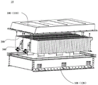
Referring to fig. 2, fig. 2 is an exploded view of a battery 10 according to some embodiments of the present disclosure. The battery 10 includes a case 100 and a battery cell 200, and the battery cell 200 is accommodated in the case 100. The case 100 is used to provide a receiving space for the battery cells 200, and the case 100 may have various structures. In some embodiments, the case 100 may include a first portion 110 and a second portion 120, the first portion 110 and the second portion 120 cover each other, and the first portion 110 and the second portion 120 together define a receiving space for receiving the battery cell 200. The second part 120 may be a hollow structure with an open end, the first part 110 may be a plate-shaped structure, and the first part 110 covers the open side of the second part 120, so that the first part 110 and the second part 120 together define a receiving space; the first portion 110 and the second portion 120 may be both hollow structures with one side open, and the open side of the first portion 110 may cover the open side of the second portion 120. Of course, the box 100 formed by the first portion 110 and the second portion 120 may have various shapes, such as a cylinder, a rectangular parallelepiped, and the like.
In the battery 10, the number of the battery cells 200 may be multiple, and the multiple battery cells 200 may be connected in series or in parallel or in series-parallel, where in series-parallel refers to both series connection and parallel connection among the multiple battery cells 200. The plurality of battery cells 200 can be directly connected in series or in parallel or in series-parallel, and the whole formed by the plurality of battery cells 200 is accommodated in the box body 100; of course, the battery 10 may also be a battery module formed by connecting a plurality of battery cells 200 in series, in parallel, or in series-parallel, and a plurality of battery modules are connected in series, in parallel, or in series-parallel to form a whole and are accommodated in the case 100. The battery 10 may further include other structures, for example, the battery 10 may further include a bus member for achieving electrical connection between the plurality of battery cells 200.
Wherein, each battery cell 200 may be a secondary battery or a primary battery; but is not limited to, a lithium sulfur battery, a sodium ion battery, or a magnesium ion battery. The battery cell 200 may be cylindrical, flat, rectangular parallelepiped, or other shapes.
The battery 10 may further include a cooling system 300, and the cooling system 300 may be disposed at the bottom of the case 100, or the cooling system 300 may be disposed between the rows of the battery cells 200, which may be set according to actual circumstances.
The cooling system 300 may include a plurality of pipe assemblies 300a, and a coolant may circulate through the plurality of pipe assemblies 300a, and may draw heat away from the battery 10, ensure uniform distribution of the temperature of the battery 10, and provide a higher heat exchange rate and a faster cooling rate.
The coolant used for heat exchange may be various, and for example, it may be a liquid refrigerant such as water, or it may be a gaseous refrigerant such as air.
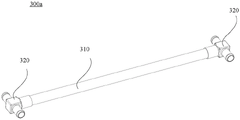
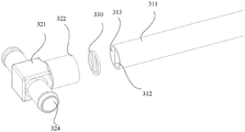
FIG. 3 is a schematic structural view of a manifold assembly according to some embodiments of the present application; FIG. 4 is an exploded view of a portion of the structure of FIG. 3; FIG. 5 is a schematic view of a portion of a circuit according to some embodiments of the present application; FIG. 6 is a schematic diagram of a tubing connector according to some embodiments of the present application.
Referring to fig. 3 to 6, the present embodiment provides a pipeline assembly 300a, including: a pipeline 310 and a pipeline connector 320, wherein the pipeline 310 comprises a pipe body 311 and a first partition 312 arranged in the pipe body 311, and the first partition 312 is used for dividing the inner space of the pipe body 311 into a plurality of first channels 313 capable of communicating two ends of the pipeline 310; the pipe connector 320 includes a body 321 and a connection portion 322 provided to the body 321, a second partition (not shown) for dividing an inner space of the body 321 into a plurality of second passages 324 respectively penetrating the body 321 is provided inside the body 321, and the connection portion 322 is for connecting with an end of the pipe 310 so that one end of each of the second passages 324 communicates with one of the first passages 313.
The line assembly 300a can be used for the circulation of gaseous and/or liquid media, in particular for the circulation of coolant. The pipe assembly 300a may be used not only in the cooling system 300 for the battery, but also in the cooling system for other devices, or in a pipe system in which a plurality of fluid media are required to be circulated at the same time. It is understood that only one pipeline 310 and two pipeline connectors 320 connected to two ends of the pipeline 310 are shown in fig. 3, and in other embodiments, the pipeline assembly 300a may further include one or more pipelines 310 or one or more pipeline connectors 320, which may be specifically configured according to the requirement.
The pipe 310 may include a pipe body 311 and a first partition 312, the pipe body 311 may be a main structure of the pipe 310, and may have a tubular structure with both ends open, and the pipe body 311 may be a straight pipe extending in a straight line direction or a curved pipe extending in a curved line direction. The cross-sectional shape of the tube 311 can be various, such as circular, square, triangular, wavy or elliptical, and the like, and the shape of the tube 311 can be adjusted according to the required internal space requirement. In some embodiments, the tube 311 may be a curved tube with a circular cross section, and the radius of the outer axis fillet at the corner is greater than 1 times the outer diameter of the tube 310, so as to facilitate the manufacturing of the tube 310.
The first separating portion 312 is disposed in the tube body 311, and the first separating portion 312 can be used for separating an inner space of the tube body 311, and it can be understood that the first separating portion 312 can extend from one end of the tube body 311 to the other end of the tube body 311, so that the inner space of the tube body 311 can be separated into a plurality of first channels 313, and each of the first channels 313 can communicate with two ends of the tube body 311.
The first partition 312 may have various structures, for example, a cross section perpendicular to the extending direction of the pipe body 311 may be a cross section of the pipe 310, and the cross section of the first partition 312 may have a shape of a letter "line", "cross", or a "meter", so that the internal space of the pipe body 311 may be substantially equally divided. For another example, the first partition 312 may include a plurality of plate-shaped structures spaced apart in any radial direction of the pipe body 311, so that the inner space of the pipe body 311 may be partitioned into the plurality of first passages 313. The shape of each first channel 313 may be the same or different, and the shape of the first channel 313 is not limited in this embodiment.
The pipe connector 320 may be connected to one end of the pipe body 311, and may serve as a transfer function between a plurality of pipes, thereby achieving connection between the plurality of pipes.
The line connector 320 may include: the body 321 and the connecting portion 322, the shape of the body 321 may be various, for example, a cuboid, a cube, a sphere, or a T shape, and the shape may be specifically set according to the number of pipelines required to be switched. It will be appreciated that the body 321 also has a cavity therein for the passage of a fluid medium.
The second partition part is disposed in the main body 321, and may have various shapes, for example, it may also have a flat plate structure, or an arc-shaped plate structure, etc., and the second partition part may divide the inner space of the main body 321 into a plurality of second channels 324, and it can be understood that each of the second channels 324 can penetrate through the main body 321, that is, the fluid medium passing through the second channel 324 can flow into the main body 321 from one end of the main body 321, and then flow out of the main body 321 from the other end. The shape of each second channel 324 may be the same or different. The number of first channels 313 corresponds to the number of second channels 324.
The connecting portion 322 may be disposed on the body 321, and the two may be processed into an integral piece by an integral forming process, or the connecting portion 322 and the body 321 may be different components, and the two are fixedly connected by a common connecting manner. The connection portion 322 may be connected to an end of the pipeline 310 by various connection methods such as clamping, screwing, welding, etc. Each second passage 324 may be in communication with one first passage 313 when the connection 322 and the tube 310 are connected.
Taking the pipeline 310 with two first channels 313 as an example, the pipeline connector 320 has two second channels 324, wherein one second channel 324 is communicated with one first channel 313, and the other second channel 324 is communicated with the second first channel 313, so that two independent flow channels are provided in the pipeline assembly 300a, when the pipeline assembly 300a is used in a cooling system, low-temperature coolant can flow into one second channel 324 from the first channel 313, so as to form high-temperature coolant after exchanging heat with the battery, and high-temperature coolant can flow into the second first channel 313 from the other second channel 324 and then flow out of the cooling system, so that inflow of low-temperature coolant and outflow of high-temperature coolant can be simultaneously achieved by using the pipeline assembly 300a, the number of pipelines in the cooling system can be reduced, so that a multi-channel function can be achieved in a smaller space, the space occupied by the cooling system is reduced.
With continued reference to fig. 5 and 6, according to some embodiments of the present application, the connection portion 322 includes a plurality of sub-connection segments 322a disposed on the body 321, each sub-connection segment 322a is inserted into one first channel 313, and a sub-channel 322c for communicating one first channel 313 and one second channel 324 is disposed inside each sub-connection segment 322 a.
The sub-connection section 322a may be connected to the body 321 by a conventional connection means, or the sub-connection section 322a may be processed as a single body with the body 321 by an integral molding process.
The number of the sub-connection segments 322a may correspond to the number of the first channels 313, i.e., each sub-connection segment 322a is disposed corresponding to one first channel 313.
Each sub-connecting section 322a may also be a hollow structure, that is, the sub-connecting section 322a has a sub-channel 322b therein, and one end of the sub-channel 322b may be connected to a second channel 324 in the body 321, and the other end may be connected to a first channel 313.
In addition, the cross-sectional dimension of each sub connection segment 322a, taken as a cross-section of the sub passage 322b in a section perpendicular to the communication direction of the sub passage 322b, may be smaller than or equal to the cross-sectional dimension of the first passage 313 to which it is connected, thereby enabling the sub connection segment 322a to be inserted into the first passage 313.
By arranging the sub-connecting section 322a capable of being inserted into the first channel 313, the connection between the pipeline 310 and the pipeline connector 320 can be facilitated, and the communication between the first channel 313 and the second channel 324 can be realized, so that the structure is simple and easy to realize.
In some embodiments, the outer surface of each sub-connecting section 322a is in interference fit connection with the channel wall of the first channel 313 in which the sub-connecting section 322a is inserted.
It can be understood that the cross-sectional dimension of the outer surface of the sub-connection section 322a may be slightly larger than the cross-sectional dimension of the first channel 313 into which the sub-connection section 322a is inserted, so that after the sub-connection section 322a is inserted into the first channel 313, the outer surface of the sub-connection section 322a can clamp the channel wall of the first channel 313, which is beneficial to achieve the sealing between the two, and improve the condition that the fluid medium is easy to leak from between the sub-connection section 322a and the channel wall of the first channel 313.
In some embodiments, the maximum cross-sectional area of the sub connection section 322a is equal everywhere in a cross section perpendicular to the communication direction of the sub passage 322 b.
The communication direction of each sub-connection section 322a may be the flow direction of the fluid medium in the sub-connection section 322a, and the maximum cross-sectional area of the sub-connection section 322a being equal everywhere may mean that the sub-connection section 322a has a constant cross-sectional structure, i.e., the shape and size of any cross-section along the communication direction thereof are the same.
The structure is simple, the processing is easy, the contact area between the sub-connecting section 322a and the channel wall of the first channel 313 can be increased, and the sealing effect of the pipeline assembly 300a is improved.
In some embodiments, the maximum cross-sectional area of the sub connection section 322a is gradually decreased in a direction from the second passage 324 toward the first passage 313, in a cross section perpendicular to the communication direction of the sub passage 322 b.
It will be appreciated that the sub-connecting segment 322a may be of a variable cross-sectional configuration, i.e., the maximum cross-sectional area may decrease from one end proximate the second passageway 324 to the other end proximate the first passageway 313, for example, the sub-connecting segment 322a may be of a tapered or wedge configuration.
The sub-connecting section 322a is configured to have a variable cross-section structure, so that it can play a guiding role to facilitate the insertion of the sub-connecting section 322a into the first channel 313.
In some embodiments, the connecting portion 322 further includes a mounting portion 322c disposed on the body 321, the mounting portion 322c is disposed around the plurality of sub-connecting sections 322a, and a groove 325 for accommodating a portion of the pipeline 310 is formed among the body 321, the mounting portion 322c and the plurality of sub-connecting sections 322 a.
Referring to fig. 6, the sub-connecting sections 322a and the mounting portion 322c may be connected to a surface of the body 321, and the mounting portion 322c may be a ring structure, which may be sleeved outside the sub-connecting sections 322a, so that a groove 325 may be defined between the sub-connecting sections 322a, the mounting portion 322c, and the surface of the body 321. The surface of the body 321 may constitute a bottom wall of the groove 325, and the surface of the mounting portion 322c facing the plurality of sub-connecting sections 322a may constitute a side wall of the groove 325. The recess 325 may be configured to receive an end of the tube 310 therein.
That is, when the sub-connection section 322a is inserted into the first passage 313, a portion of the tube body 311 positioned at the outer periphery of the sub-connection section 322a may be received in the groove 325, so that the coupling strength between the tube 310 and the tube coupling member 320 may be improved.
In some embodiments, the outer surface of the tube 311 abuts the inner surface of the mounting portion 322 c.
It will be appreciated that the outer surface of the tube 311 may be interference fit to the inner surface of the mounting portion 322c, i.e. the outer surface of the tube 311 may abut against the side wall of the groove 325, and the end of the tube 311 may be snapped into the groove 325, further improving the connection strength and sealing effect between the pipeline 310 and the pipeline connector 320.
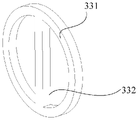
FIG. 7 is a schematic diagram of a seal according to some embodiments of the present application. Referring to fig. 4 and 7, in some embodiments, the conduit assembly 300a further includes: a seal 330, the seal 330 being disposed between the pipe 310 and the pipe connector 320.
The sealing member 330 may be made of a common sealing material such as butyl cyanide rubber, ethylene propylene diene monomer, fluororubber, silica gel, fluorosilicone rubber, nylon, polyurethane, engineering plastic, or the like.
The sealing member 330 may be tightly coupled between the pipe 310 and the pipe connector 320 by virtue of the coupling force therebetween.
The sealing member 330 may be coupled between the pipe 310 and the pipe connector 320, and may serve to prevent fluid from leaking between adjacent coupling surfaces and prevent foreign substances, such as dust or moisture, from intruding into the inside of the pipe assembly 300a, thereby performing a sealing function such that a plurality of channels in the pipe assembly 300a may be isolated from each other and sealing reliability between the first channel 313 and the second channel 324 in each channel may be improved.
In some embodiments, the seal 330 abuts between the end face of the tube 310 and the bottom wall of the groove 325.
The sealing member 330 may be a sheet-like structure, one side surface of which may abut against the end surface of the pipeline 310 and the other side surface of which may abut against the bottom wall of the groove 325, so as to seal the pipeline 310 and the pipeline connector 320 by sealing the end surface of the pipeline 310 and the bottom wall of the groove 325.
When the pipeline connector is installed, the sealing element 330 can be firstly placed in the groove 325 to be attached to the bottom wall, then the pipeline 310 can be inserted into the groove 325, the pipeline 310 and the pipeline connector 320 can be installed, sealing is achieved, and meanwhile the installation of the sealing element 330 can be simplified.
With continued reference to fig. 7, in some embodiments, the sealing member 330 includes a ring-shaped body 331 and a separator 332 connected in the ring-shaped body 331, wherein the ring-shaped body 331 abuts against an end surface of the tube 311, and the separator 332 abuts against an end surface of the first separating portion 312.
The ring-shaped body 331 may have a ring-shaped structure, and the shape thereof may be set according to the shape of the end surface of the tube body 311, for example, the cross section of the tube body 311 may be circular, and the ring-shaped body 331 may have an annular shape.
The partition body 332 may be provided according to the shape of the first partition 312, for example, the cross-section of the first partition 312 may be in a line shape, and the partition body 332 may also be in a line shape.
In addition, in some embodiments, the annular body 331 and the separating body 332 may be integrally formed by an integral molding process to further improve the sealing effect.
It can be understood that the ring-shaped body 331 can be used to prevent the fluid in the pipeline 310 from overflowing the pipeline assembly 300a and prevent impurities such as dust from entering the pipeline assembly 300a, and the separating body 332 can be used to separate a plurality of flow channels in the pipeline assembly 300a, so as to prevent the fluid from mixing with each other between the flow channels, and achieve a better sealing effect.
In some embodiments, the tube 311 is fixedly connected to the mounting portion 322c by at least one of welding, bonding, and interference fit.
The tube 311 and the mounting portion 322c may be connected by interference fit, or may be connected by welding, bonding, or the like, or the tube 311 and the mounting portion 322c may be connected by interference fit and welding at the same time.
Taking welding as an example, during installation, the sealing element 330 may be first placed in the groove 325 to be attached to the bottom wall, then the pipeline 310 may be inserted into the groove 325 to implement installation of the pipeline 310 and the pipeline connector 320, and finally, a welding operation may be performed along a gap between the pipe body 311 and the installation portion 322c to implement fixed connection of the two.
By fixing the pipe body 311 and the mounting portion 322c to each other, the fastening strength and the sealing property of the pipe assembly 300a can be improved.
In some embodiments, line connector 320 includes: a plurality of joints 326 for connecting with other pipelines; a plurality of joints 326 are convexly disposed on the body 321, and an end of each second channel 324 facing away from the first channel 313 further penetrates through the joint 326 along an extending direction of the joint 326.
Each joint portion 326 may protrude from the body 321, and may be a circular tubular structure or other tubular structures, and the joint portion 326 may be connected to other pipelines by snapping or screwing, so as to form the entire cooling system. It will be appreciated that the other lines may be a line structure having one flow passage inside, or may be a structure of the pipe 310 having a plurality of flow passages.
The number of joints 326 may be the same as the number of second channels 324, such that each joint 326 receives one second channel 324 therein, although in some embodiments, a plurality of second channels 324 may also share one joint 326, i.e., one joint 326 may receive a plurality of second channels 324 therein.
By providing the joint portion 326, it is possible to connect a plurality of flow passages in the pipe assembly 300a to other pipes, thereby forming the multi-pipe cooling system 300.
According to some embodiments of the present application, there is also provided a cooling system 300, the cooling system 300 comprising a pipe assembly 300a as described in any of the above embodiments, the pipe assembly 300a being for circulating coolant.
According to some embodiments of the present application, there is also provided a battery 10 comprising a cooling system 300 as in any of the embodiments described above.
According to some embodiments of the present application, there is also provided an electrical device comprising a battery 10 as in any of the above embodiments, and the battery 10 is used to provide electrical energy to the electrical device.
The powered device may be any of the aforementioned battery-powered devices or systems.
In one embodiment, the pipeline assembly 300a may include a pipeline 310, a pipeline connector 320 and a sealing member 330 connected between the pipeline 310 and the pipeline connector 320, the pipeline 310 is provided with a first partition 312, the first partition 312 may divide the pipe body 311 into two first channels 313 which are not communicated with each other, the body 321 of the pipeline connector 320 is provided with a second partition which may divide the body 321 into two second channels 324, and the pipeline connector 320 further includes a connecting portion 322, the connecting portion 322 includes two sub-connecting sections 322a and a mounting portion 322c which is arranged around the sub-connecting section 322a, each sub-connecting section 322a may be inserted into one first channel 313, so as to communicate one first channel 313 and one second channel 324 through a sub-channel 322b inside the sub-connecting section 322 a. The mounting portion 322c and the body 321 and the plurality of sub-connection segments 322a may enclose a groove 325, and the end of the pipe 310 may be snapped into the groove 325. The pipe connector 320 is further provided with a plurality of coupling portions 326 for connecting other pipes.
Finally, it should be noted that: the above embodiments are only used for illustrating the technical solutions of the present application, and not for limiting the same; although the present application has been described in detail with reference to the foregoing embodiments, it should be understood by those of ordinary skill in the art that: the technical solutions described in the foregoing embodiments may still be modified, or some or all of the technical features may be equivalently replaced; such modifications and substitutions do not depart from the spirit and scope of the present disclosure, and the present disclosure should be construed as being covered by the claims and the specification. In particular, the technical features mentioned in the embodiments can be combined in any way as long as there is no structural conflict. The present application is not intended to be limited to the particular embodiments disclosed herein but is to cover all embodiments that may fall within the scope of the appended claims.
Claims (15)
1. A manifold assembly, comprising:
the pipeline comprises a pipe body and a first partition part arranged in the pipe body, wherein the first partition part is used for dividing the inner space of the pipe body into a plurality of first channels capable of communicating two ends of the pipeline; and
the pipeline connecting piece comprises a body and a connecting part arranged on the body, wherein a second partition part is arranged inside the body and used for dividing the inner space of the body into a plurality of second channels which are respectively communicated with the body, and the connecting part is used for being connected with the end part of a pipeline so as to enable one end of each second channel to be communicated with one first channel.
2. The manifold assembly of claim 1,
the connecting part comprises a plurality of sub-connecting sections arranged on the body, each sub-connecting section is inserted into one first channel, and a sub-channel used for communicating one first channel with one second channel is arranged in each sub-connecting section.
3. The manifold assembly of claim 2,
the outer surface of each sub-connecting section is connected with the channel wall of the first channel inserted with the sub-connecting section in an interference fit manner.
4. The manifold assembly of claim 2,
and taking a section vertical to the communication direction of the sub-channel as a cross section, wherein the maximum cross section area of the sub-connecting section is equal everywhere.
5. The manifold assembly of claim 2,
and the section perpendicular to the communication direction of the sub-channels is taken as a cross section, and the maximum cross-sectional area of the sub-connecting section is gradually reduced along the direction from the second channel to the first channel.
6. A pipe assembly according to any one of claims 2-5,
connecting portion still including set up in the installation department of body, the installation department encloses to be located a plurality of sub-linkage segments are peripheral, just the body the installation department with form between a plurality of sub-linkage segments and be used for the accommodation portion the recess of pipeline.
7. The manifold assembly of claim 6,
the outer surface of the pipe body abuts against the inner surface of the mounting portion.
8. The manifold assembly of claim 6,
the tubing assembly further comprises: a seal disposed between the pipeline and the pipeline connector.
9. The manifold assembly of claim 8,
the sealing element is abutted between the end face of the pipeline and the bottom wall of the groove.
10. The manifold assembly of claim 9,
the sealing element comprises a ring-shaped body and a separating body connected into the ring-shaped body, the ring-shaped body is abutted against the end face of the pipe body, and the separating body is abutted against the end face of the first separating part.
11. The manifold assembly of claim 6, wherein the tubular body is fixedly coupled to the mounting portion by at least one of welding, bonding, and interference fit.
12. The piping component of any of claims 1-5, wherein said piping connection comprises: a plurality of joint portions for connecting with other pipelines; the plurality of joint parts are arranged on the body in a protruding mode, and one end, deviating from the first channel, of each second channel penetrates through the joint part along the extending direction of one joint part.
13. A cooling system, characterized in that it comprises a pipe assembly according to any one of claims 1-12 for the circulation of coolant.
14. A battery comprising a cooling system as claimed in claim 13.
15. An electrical consumer, characterized in that the consumer comprises a battery according to claim 14 for providing electrical energy.
Priority Applications (1)
| Application Number | Priority Date | Filing Date | Title |
|---|---|---|---|
| CN202210546663.8A CN114665194B (en) | 2022-05-20 | 2022-05-20 | Pipeline assembly, cooling device, battery and electric device |
Applications Claiming Priority (1)
| Application Number | Priority Date | Filing Date | Title |
|---|---|---|---|
| CN202210546663.8A CN114665194B (en) | 2022-05-20 | 2022-05-20 | Pipeline assembly, cooling device, battery and electric device |
Publications (2)
| Publication Number | Publication Date |
|---|---|
| CN114665194A true CN114665194A (en) | 2022-06-24 |
| CN114665194B CN114665194B (en) | 2022-09-27 |
Family
ID=82037640
Family Applications (1)
| Application Number | Title | Priority Date | Filing Date |
|---|---|---|---|
| CN202210546663.8A Active CN114665194B (en) | 2022-05-20 | 2022-05-20 | Pipeline assembly, cooling device, battery and electric device |
Country Status (1)
| Country | Link |
|---|---|
| CN (1) | CN114665194B (en) |
Cited By (2)
| Publication number | Priority date | Publication date | Assignee | Title |
|---|---|---|---|---|
| CN115051011A (en) * | 2022-08-17 | 2022-09-13 | 杭州德海艾科能源科技有限公司 | Liquid flow battery galvanic pile liquid path partition system |
| CN116045109A (en) * | 2023-04-03 | 2023-05-02 | 宁德时代新能源科技股份有限公司 | Integrated multi-way flange, battery and electric equipment |
Citations (7)
| Publication number | Priority date | Publication date | Assignee | Title |
|---|---|---|---|---|
| CN102767922A (en) * | 2012-08-10 | 2012-11-07 | 天津三电汽车空调有限公司 | Distributing pipe for micro-channel heat exchanger and micro-channel heat exchanger |
| CN106206494A (en) * | 2016-08-29 | 2016-12-07 | 华霆(合肥)动力技术有限公司 | The cold pipe of flat tube, liquid and liquid cooling apparatus |
| CN107477213A (en) * | 2016-06-08 | 2017-12-15 | 杭州三花研究院有限公司 | Volume control device and its manufacture method |
| CN207207695U (en) * | 2017-09-30 | 2018-04-10 | 宁波新华泰模塑电器有限公司 | A kind of car duct component |
| CN108400408A (en) * | 2018-04-24 | 2018-08-14 | 华南理工大学 | It is a kind of that there is fire-retardant Vehicular dynamic battery multichannel liquid cooling apparatus |
| US20190081374A1 (en) * | 2017-09-11 | 2019-03-14 | Mahle International Gmbh | Traction battery with battery temperature control system |
| CN210800150U (en) * | 2019-11-08 | 2020-06-19 | 江苏亨昇精密机械科技有限公司 | One-way valve for automobile cooling pipeline |
-
2022
- 2022-05-20 CN CN202210546663.8A patent/CN114665194B/en active Active
Patent Citations (8)
| Publication number | Priority date | Publication date | Assignee | Title |
|---|---|---|---|---|
| CN102767922A (en) * | 2012-08-10 | 2012-11-07 | 天津三电汽车空调有限公司 | Distributing pipe for micro-channel heat exchanger and micro-channel heat exchanger |
| CN107477213A (en) * | 2016-06-08 | 2017-12-15 | 杭州三花研究院有限公司 | Volume control device and its manufacture method |
| CN106206494A (en) * | 2016-08-29 | 2016-12-07 | 华霆(合肥)动力技术有限公司 | The cold pipe of flat tube, liquid and liquid cooling apparatus |
| US20190081374A1 (en) * | 2017-09-11 | 2019-03-14 | Mahle International Gmbh | Traction battery with battery temperature control system |
| CN109494426A (en) * | 2017-09-11 | 2019-03-19 | 马勒国际有限公司 | The traction battery of charged pool temperature control system |
| CN207207695U (en) * | 2017-09-30 | 2018-04-10 | 宁波新华泰模塑电器有限公司 | A kind of car duct component |
| CN108400408A (en) * | 2018-04-24 | 2018-08-14 | 华南理工大学 | It is a kind of that there is fire-retardant Vehicular dynamic battery multichannel liquid cooling apparatus |
| CN210800150U (en) * | 2019-11-08 | 2020-06-19 | 江苏亨昇精密机械科技有限公司 | One-way valve for automobile cooling pipeline |
Non-Patent Citations (1)
| Title |
|---|
| 叶勤友: "多通道连续油管地面分层注水技术研究", 《西安石油大学学报(自然科学版)》 * |
Cited By (3)
| Publication number | Priority date | Publication date | Assignee | Title |
|---|---|---|---|---|
| CN115051011A (en) * | 2022-08-17 | 2022-09-13 | 杭州德海艾科能源科技有限公司 | Liquid flow battery galvanic pile liquid path partition system |
| CN115051011B (en) * | 2022-08-17 | 2022-11-15 | 杭州德海艾科能源科技有限公司 | Liquid flow battery galvanic pile liquid path partition system |
| CN116045109A (en) * | 2023-04-03 | 2023-05-02 | 宁德时代新能源科技股份有限公司 | Integrated multi-way flange, battery and electric equipment |
Also Published As
| Publication number | Publication date |
|---|---|
| CN114665194B (en) | 2022-09-27 |
Similar Documents
| Publication | Publication Date | Title |
|---|---|---|
| CN114665194B (en) | Pipeline assembly, cooling device, battery and electric device | |
| CN216354420U (en) | Battery box, battery and power consumption device | |
| CN105280850B (en) | Intelligent heat management waterproof power battery box | |
| KR20240055134A (en) | Water cooling plate assembly, water cooling system, cell and its box, and electrical device | |
| CN216698504U (en) | Battery and electric device | |
| CN216903119U (en) | Battery thermal management system, battery and power consumption device | |
| WO2023078187A1 (en) | Battery pack, thermal management system of battery, and electric device | |
| WO2024109478A1 (en) | Heat exchange assembly, battery, and electric device | |
| CN217764637U (en) | Pipe joint, connecting structure, heat exchange system, battery and power utilization device | |
| CN218602559U (en) | Thermal management component, battery and electric device | |
| CN216354419U (en) | Cooling structure and battery package | |
| CN221530045U (en) | Battery box, battery and power consumption device | |
| CN221928278U (en) | Battery device and electricity utilization device | |
| CN218827418U (en) | Battery cooling pipe, battery cooling assembly, battery module and battery pack | |
| CN220774513U (en) | Heat exchange assembly, battery and electric equipment | |
| CN116221515B (en) | Pipeline connecting assembly, liquid cooling system, battery and electricity utilization device | |
| CN220510175U (en) | Battery and electricity utilization device | |
| CN218267826U (en) | Floating joint, heat exchange system, battery and power consumption device | |
| CN221885215U (en) | Battery and electricity utilization device | |
| CN221928272U (en) | Battery device and power utilization device | |
| CN220065842U (en) | Pipeline connecting assembly, battery box, battery, electric equipment and energy storage equipment | |
| CN221097145U (en) | Nut, connecting structure and vehicle | |
| CN220710413U (en) | Heat exchange assembly, battery and power utilization device | |
| CN220420699U (en) | Thermal management component, battery and electricity utilization device | |
| CN220341304U (en) | Thermal management device, battery and electricity utilization device |
Legal Events
| Date | Code | Title | Description |
|---|---|---|---|
| PB01 | Publication | ||
| PB01 | Publication | ||
| SE01 | Entry into force of request for substantive examination | ||
| SE01 | Entry into force of request for substantive examination | ||
| GR01 | Patent grant | ||
| GR01 | Patent grant |