CN114622481A - Double-column type self-resetting pier structure with buckling-restrained brace and construction method thereof - Google Patents
Double-column type self-resetting pier structure with buckling-restrained brace and construction method thereof Download PDFInfo
- Publication number
- CN114622481A CN114622481A CN202210331665.5A CN202210331665A CN114622481A CN 114622481 A CN114622481 A CN 114622481A CN 202210331665 A CN202210331665 A CN 202210331665A CN 114622481 A CN114622481 A CN 114622481A
- Authority
- CN
- China
- Prior art keywords
- plate
- pier
- energy dissipation
- steel plate
- bearing platform
- Prior art date
- Legal status (The legal status is an assumption and is not a legal conclusion. Google has not performed a legal analysis and makes no representation as to the accuracy of the status listed.)
- Granted
Links
- 238000010276 construction Methods 0.000 title claims abstract description 19
- 230000021715 photosynthesis, light harvesting Effects 0.000 claims abstract description 165
- 229910000831 Steel Inorganic materials 0.000 claims abstract description 156
- 239000010959 steel Substances 0.000 claims abstract description 156
- 239000004567 concrete Substances 0.000 claims abstract description 46
- 210000002435 tendon Anatomy 0.000 claims abstract description 27
- 238000005265 energy consumption Methods 0.000 claims description 78
- 239000011150 reinforced concrete Substances 0.000 claims description 17
- 238000007906 compression Methods 0.000 claims description 16
- 230000006835 compression Effects 0.000 claims description 15
- 238000000034 method Methods 0.000 claims description 15
- 238000004873 anchoring Methods 0.000 claims description 12
- 238000012423 maintenance Methods 0.000 claims description 10
- 238000004519 manufacturing process Methods 0.000 claims description 9
- 238000013461 design Methods 0.000 claims description 8
- 239000011148 porous material Substances 0.000 claims description 7
- 239000003822 epoxy resin Substances 0.000 claims description 6
- 239000003292 glue Substances 0.000 claims description 6
- 229920000647 polyepoxide Polymers 0.000 claims description 6
- 230000000452 restraining effect Effects 0.000 claims description 6
- 238000012545 processing Methods 0.000 claims description 5
- 229910000838 Al alloy Inorganic materials 0.000 claims description 4
- 239000000956 alloy Substances 0.000 claims description 4
- 230000010485 coping Effects 0.000 claims description 4
- 210000001503 joint Anatomy 0.000 claims description 4
- 229910001209 Low-carbon steel Inorganic materials 0.000 claims description 3
- 239000004568 cement Substances 0.000 claims description 3
- 239000011248 coating agent Substances 0.000 claims description 3
- 238000000576 coating method Methods 0.000 claims description 3
- 238000001514 detection method Methods 0.000 claims description 3
- 239000000428 dust Substances 0.000 claims description 3
- 238000007667 floating Methods 0.000 claims description 3
- 239000002023 wood Substances 0.000 claims description 3
- 238000005452 bending Methods 0.000 claims description 2
- 229910001285 shape-memory alloy Inorganic materials 0.000 description 27
- 230000009471 action Effects 0.000 description 17
- 238000006073 displacement reaction Methods 0.000 description 13
- 230000000694 effects Effects 0.000 description 13
- 230000006378 damage Effects 0.000 description 9
- 238000010008 shearing Methods 0.000 description 8
- 230000008569 process Effects 0.000 description 7
- 238000009434 installation Methods 0.000 description 5
- 230000006870 function Effects 0.000 description 4
- 239000004033 plastic Substances 0.000 description 4
- 239000000463 material Substances 0.000 description 3
- 230000035939 shock Effects 0.000 description 3
- 229910001294 Reinforcing steel Inorganic materials 0.000 description 2
- 230000007797 corrosion Effects 0.000 description 2
- 238000005260 corrosion Methods 0.000 description 2
- 230000007123 defense Effects 0.000 description 2
- 238000010586 diagram Methods 0.000 description 2
- 230000002787 reinforcement Effects 0.000 description 2
- 230000008439 repair process Effects 0.000 description 2
- 239000002436 steel type Substances 0.000 description 2
- 230000002459 sustained effect Effects 0.000 description 2
- OKTJSMMVPCPJKN-UHFFFAOYSA-N Carbon Chemical compound [C] OKTJSMMVPCPJKN-UHFFFAOYSA-N 0.000 description 1
- 230000002411 adverse Effects 0.000 description 1
- 238000004458 analytical method Methods 0.000 description 1
- QVGXLLKOCUKJST-UHFFFAOYSA-N atomic oxygen Chemical compound [O] QVGXLLKOCUKJST-UHFFFAOYSA-N 0.000 description 1
- 230000009286 beneficial effect Effects 0.000 description 1
- 238000004364 calculation method Methods 0.000 description 1
- 229910052799 carbon Inorganic materials 0.000 description 1
- 238000004140 cleaning Methods 0.000 description 1
- 238000013016 damping Methods 0.000 description 1
- 238000011161 development Methods 0.000 description 1
- 238000009826 distribution Methods 0.000 description 1
- 238000004134 energy conservation Methods 0.000 description 1
- 230000007613 environmental effect Effects 0.000 description 1
- 238000001125 extrusion Methods 0.000 description 1
- 238000011835 investigation Methods 0.000 description 1
- 238000012986 modification Methods 0.000 description 1
- 230000004048 modification Effects 0.000 description 1
- 229910052760 oxygen Inorganic materials 0.000 description 1
- 239000001301 oxygen Substances 0.000 description 1
- 238000005498 polishing Methods 0.000 description 1
- 238000011084 recovery Methods 0.000 description 1
- 230000009467 reduction Effects 0.000 description 1
- 230000003014 reinforcing effect Effects 0.000 description 1
- 238000011160 research Methods 0.000 description 1
- 239000000126 substance Substances 0.000 description 1
- XLYOFNOQVPJJNP-UHFFFAOYSA-N water Substances O XLYOFNOQVPJJNP-UHFFFAOYSA-N 0.000 description 1
Images


Classifications
-
- E—FIXED CONSTRUCTIONS
- E01—CONSTRUCTION OF ROADS, RAILWAYS, OR BRIDGES
- E01D—CONSTRUCTION OF BRIDGES, ELEVATED ROADWAYS OR VIADUCTS; ASSEMBLY OF BRIDGES
- E01D19/00—Structural or constructional details of bridges
- E01D19/02—Piers; Abutments ; Protecting same against drifting ice
-
- E—FIXED CONSTRUCTIONS
- E01—CONSTRUCTION OF ROADS, RAILWAYS, OR BRIDGES
- E01D—CONSTRUCTION OF BRIDGES, ELEVATED ROADWAYS OR VIADUCTS; ASSEMBLY OF BRIDGES
- E01D19/00—Structural or constructional details of bridges
-
- Y—GENERAL TAGGING OF NEW TECHNOLOGICAL DEVELOPMENTS; GENERAL TAGGING OF CROSS-SECTIONAL TECHNOLOGIES SPANNING OVER SEVERAL SECTIONS OF THE IPC; TECHNICAL SUBJECTS COVERED BY FORMER USPC CROSS-REFERENCE ART COLLECTIONS [XRACs] AND DIGESTS
- Y02—TECHNOLOGIES OR APPLICATIONS FOR MITIGATION OR ADAPTATION AGAINST CLIMATE CHANGE
- Y02A—TECHNOLOGIES FOR ADAPTATION TO CLIMATE CHANGE
- Y02A30/00—Adapting or protecting infrastructure or their operation
- Y02A30/30—Adapting or protecting infrastructure or their operation in transportation, e.g. on roads, waterways or railways
Abstract
The invention provides a double-column type self-resetting pier structure with buckling restrained braces and a construction method thereof. The bridge pier structure comprises a capping beam, a bearing platform and two groups of segment bridge pier bodies, wherein the segment bridge pier bodies are connected with the capping beam and the bearing platform through unbonded prestressed tendons; a built-in energy dissipation device is arranged at the joint of each group of segmental pier bodies and the bearing platform, and comprises a T-shaped steel plate, a concave steel plate and an energy dissipation rod; be equipped with between two sets of section pier bodies and be two buckling restrained brace that the chevron shape distributes, buckling restrained brace includes and is formed square sleeve structure by upper and lower sleeve through the connection of SMA pole to and be located upper and lower power consumption board and the power consumption piece of square sleeve structure, go up sleeve and lower sleeve and all adopt concave type steel pipe, its body intussuseption is filled with tuff concrete. The pier structure provides restoring force through the self-resetting structure, and has the advantages that the built-in energy dissipation device and the buckling restrained brace consume seismic energy and improve the lateral rigidity of the structure, and the pier structure has good practicability and economy.
Description
Technical Field
The invention relates to the field of bridge engineering, in particular to a double-column type self-resetting pier structure with buckling restrained braces and a construction method thereof.
Background
The earthquake in China has frequent earthquake activity, large intensity, shallow earthquake focus and wide distribution, and is a country with serious earthquake disasters. The bridge is used as an urban infrastructure and plays an important role in rescue after earthquake and escape of people in earthquake. The bridge pier is used as an important component in a bridge structure system and plays a role in bearing all loads of an upper structure and transmitting the loads to a foundation, so that the seismic performance of the bridge pier is very important for guaranteeing the safety of the whole bridge structure system. A large number of earthquake damage investigation results show that under the action of high axial pressure ratio and earthquake, longitudinal rib buckling, concrete peeling and the like can occur in a pier bottom plastic hinge area, so that a bridge is damaged or collapsed and is difficult to repair, and the development of emergency rescue work is influenced. In view of this, in recent years, scholars at home and abroad propose and develop novel anti-seismic structures and systems based on recoverable functional design concept, and the self-resetting structure system is composed of assembled components, is convenient and efficient to construct, has small residual displacement after earthquake, and has good self-resetting capability. However, compared with the conventional cast-in-place pier, the lateral bearing capacity and the energy consumption capacity of the self-resetting pier are poor, and the structure is collapsed and damaged due to large lateral deformation and residual deformation generated under the action of an earthquake, so that the application of the self-resetting pier in bridge engineering is hindered.
The buckling-restrained brace is used as an energy consumption device which is easy to yield, has a full hysteresis curve and a good energy consumption effect, can provide lateral rigidity for the structure under the action of small earthquake, reduces the lateral deformation of the structure, can consume earthquake energy through self buckling damage under the action of large earthquake, and protects other components through self damage, so that the residual deformation of the structure after the earthquake is reduced, and the effect similar to a fuse is achieved. However, the common types of the traditional buckling restrained brace are grouting type bracing and pure steel type bracing, and grouting type constraint materials usually adopt common concrete, so that the self weight of the member is too large, inconvenience is caused to transportation and installation, the load of the original structure can be increased, and adverse effects are caused to the structure. The pure steel type means that the whole component is made of steel, and the steel material used is more, the cost is higher, and the economical efficiency is poor. The common buckling-restrained brace device at the present stage mainly has the following problems: the assembly and disassembly difficulty is high due to the overlarge self weight, so that the construction is inconvenient; the inner core is not easy to disassemble, the replacement frequency is high, and the maintenance cost is high; the structure lacks self-recovery performance, so that the structure has larger residual deformation after the earthquake; the buckling position is not controllable, so that the buckling-restrained brace is difficult to detect and repair after an earthquake, and the maintenance cost is increased.
In addition, most of the existing bridge pier structures use anti-buckling supports as energy dissipation members independently, for example, the publication number of the patent CN 104452567B discloses a swing type double-layer bridge bent frame and an installation method thereof, the patent comprises a bent frame foundation, a group of bottom layer prefabricated bridge piers respectively arranged at the left end and the right end of the bent frame foundation, the anti-buckling supports are arranged between the bent frame foundation and the prefabricated cover beams, and the anti-buckling supports provide main transverse bridge rigidity and energy dissipation capacity; the structure in this patent is arranged under the earthquake effect and is strutted across bridge and then to rigidity and power consumption ability and then mainly undertake through buckling restrained brace, though can play certain antidetonation effect, nevertheless suffer destruction at buckling restrained brace after, its bridge construction will directly receive the influence, and pier cost of maintenance is great after the shake. And most of the existing assembly type self-resetting piers adopt flat joints, and only rely on interface friction to resist the bottom shearing force of the pier, so that large lateral displacement is easy to generate, and the shearing resistance of the structure is poor.
Disclosure of Invention
In order to solve the problem of insufficient anti-seismic performance of the self-resetting pier, the invention provides a double-column self-resetting pier structure with buckling-restrained braces and a construction method.
In order to achieve the technical purpose, the invention provides a double-column type self-resetting pier structure with buckling restrained braces, which comprises a capping beam, a bearing platform and two groups of segmental pier bodies positioned between the capping beam and the bearing platform, wherein each group of segmental pier bodies is formed by splicing multiple sections of reinforced concrete segments and is connected with the capping beam and the bearing platform through unbonded prestressed tendons; a built-in energy dissipation device is arranged at the position where each group of segmental pier bodies is connected with the bearing platform, the built-in energy dissipation device comprises a T-shaped steel plate, a concave steel plate and energy dissipation rods, the T-shaped head of the T-shaped steel plate extends into the bearing platform, and the free end of the vertical steel plate is inserted into the groove of the concave steel plate and is connected with the energy dissipation rods; two buckling restrained braces distributed in a herringbone shape are arranged between the two groups of segment pier bodies, each buckling restrained brace comprises an energy consumption restraining rod body and connectors positioned at two ends of the rod body, and the upper end and the lower end of each buckling restrained brace are respectively connected with the capping beam and the bearing platform through the connectors; the energy consumption restraint rod body comprises a square sleeve structure formed by connecting an upper sleeve and a lower sleeve through an SMA rod, and an upper energy consumption plate, a lower energy consumption plate and an energy consumption block which are positioned in the square sleeve structure; the upper sleeve and the lower sleeve are both made of concave steel pipes, tuff concrete is filled in the pipe body of the upper sleeve, the upper sleeve and the lower sleeve are connected through a plurality of SMA rods after being butted, one side of the upper energy dissipation plate is connected to the inner side of the top plate of the upper sleeve, one side of the lower energy dissipation plate is connected to the inner side of the bottom plate of the lower sleeve, the other sides of the upper energy dissipation plate and the lower energy dissipation plate are overlapped, and the overlapped areas are connected through energy dissipation blocks.
The further technical scheme of the invention is as follows: the upper surface of the bearing platform is provided with hemispherical grooves corresponding to the positions of the two groups of segment abutment bodies, the lower end surface of the reinforced concrete section at the bottom of each group of segment abutment bodies connected with the bearing platform is provided with a hemispherical joint matched with the hemispherical grooves, and the hemispherical joint at the bottom of each group of segment abutment bodies is correspondingly embedded into the hemispherical groove at the upper surface of the bearing platform.
The invention has the following excellent technical scheme: the upper energy dissipation plate and the lower energy dissipation plate are staggered and overlapped in a straight line shape, a row of circular through holes are correspondingly formed in the overlapped area, and the distance between every two adjacent circular through holes is 300-1000 mm; the energy dissipation blocks are of cylindrical structures, the diameters of the energy dissipation blocks are matched with the diameters of the circular through holes, one energy dissipation block is correspondingly inserted into each circular through hole, and the upper energy dissipation plate and the lower energy dissipation plate are connected through the energy dissipation blocks.
The invention has the following excellent technical scheme: a reserved hole matched with the outline width of the concave steel plate is formed in the reinforced concrete section of each group of section pier bodies connected with the bearing platform, a fixing plate extending outwards and horizontally is arranged at the groove opening of the concave steel plate, a bolt hole is formed in the fixing plate, the concave steel plate is arranged in the reserved hole, the fixing plate is fixedly connected with the lower end face of the reserved hole through a high-strength bolt, and a T-shaped steel plate hole channel is formed below the reserved hole; the T-shaped head of the T-shaped steel plate is arranged at a position 300-600 mm deep in the bearing platform, the vertical steel plate extends into the groove of the concave steel plate along the hole channel of the T-shaped steel plate, and the height of the T-shaped steel plate extending into the pier body of the segment is 500-1000 mm; and after the built-in energy consumption device is installed, high-grade plain concrete is filled in the reserved hole.
The invention has the following excellent technical scheme: a plurality of through holes with the diameter matched with the diameter of the energy dissipation rod are correspondingly formed in two parallel steel plates on the side surface of the concave steel plate, the through holes are distributed in a quincunx shape, a plurality of transverse stiffening ribs are arranged near the through holes of the concave steel plate, and a compression spring is arranged at the groove part of the concave steel plate; the end part of a vertical steel plate of the T-shaped steel plate is provided with a concave connecting plate, the T-shaped steel plate is embedded into a groove of the concave steel plate through the concave connecting plate at the end part, the end parts of two parallel plates of the concave connecting plate are connected with a compression spring, and through holes matched with the diameter of the energy dissipation rod are correspondingly arranged on the two parallel plate surfaces of the concave connecting plate; the energy dissipation rods are made of mild steel with low yield point, are hourglass-shaped and are provided with arc-shaped surfaces in the middle, annular grooves are symmetrically formed in the two ends of each energy dissipation rod, and each energy dissipation rod is inserted into a through hole corresponding to the T-shaped steel plate and the concave steel plate to connect the T-shaped steel plate and the concave steel plate.
The invention has the following excellent technical scheme: the upper energy consumption plate, the lower energy consumption plate and the energy consumption block are all made of aluminum alloy materials; a deformation gap of 2-5 mm is reserved between the upper energy consumption plate and the lower energy consumption plate; the yield strength of the energy dissipation blocks is lower than that of the upper energy dissipation plate and the lower energy dissipation plate; the upper energy dissipation plate and the lower energy dissipation plate are respectively connected with the upper sleeve and the lower sleeve through a plurality of sections of angle steel, a plurality of connecting holes are formed in the angle steel at equal intervals, and each energy dissipation plate is correspondingly provided with a connecting hole; the two sides of each energy dissipation plate are respectively connected with an angle steel, and the angle steels on the two sides are connected with the corresponding sleeves.
The invention has the following excellent technical scheme: each group of segmental pier bodies is connected with the capping beam and the bearing platform through a plurality of unbonded prestressed tendons, each unbonded prestressed tendon straightly penetrates through the whole pier body without bending, and two ends of each unbonded prestressed tendon are respectively anchored in the bearing platform and the capping beam through an anchorage device; connecting lug plates are correspondingly arranged in the middle of the cover beam and on the bearing platform, and the buckling-restrained brace is connected with the corresponding connecting lug plates through high-strength bolts.
The invention has the following excellent technical scheme: the size of a side plate of the lower sleeve is larger than that of a side plate of the upper sleeve, a connecting groove matched with the size of the side plate of the upper sleeve is formed in the upper surface of the side plate of the lower sleeve, limiting rubber is arranged at the bottom of an inner groove of the connecting groove, and the butt joint end of the side plate of the upper sleeve is inserted into the connecting groove of the side plate of the lower sleeve and a deformation gap is reserved; the inner walls of the groove-shaped steel pipes of the upper sleeve and the lower sleeve are provided with a plurality of vertical stiffening ribs, the top surface of the upper sleeve and the bottom surface of the lower sleeve are correspondingly provided with at least one row of SMA rod pore channels, and the SMA rods penetrate through the two ends of the SMA rod pore channels corresponding to the upper sleeve and the lower sleeve and are fixed on the outer surface of the sleeve through clamps and backing plates respectively; go up the sleeve and be equipped with a plurality of bar grooves with telescopic surface down, every bar groove perpendicular to sleeve length direction sets up, and the circular through-hole aperture that corresponds the bar groove position and the diameter of power consumption piece compare other positions and reduce to some extent.
In order to achieve the above object, the present invention further provides a construction method of a double-column type self-resetting pier structure with buckling restrained braces, which is characterized by comprising the following specific steps:
the method comprises the following steps: prefabricating a segment pier body and a cover beam. Carrying out steel bar blanking and binding work of the bent cap and the reinforced concrete section of the segment pier body according to a design drawing, and finishing the manufacture of the reinforced concrete section of the pier body of the pier and the steel bar cage of the bent cap; and reserving the prestressed tendon pore channel, the anchoring groove, the T-shaped steel plate pore channel and the reserved hole when manufacturing the bent cap and the reinforced concrete section, and finally performing concrete pouring on each component, vibrating for compacting and watering for maintenance, wherein the maintenance time is not less than 7 d.
Step two: and (5) constructing a bearing platform. Leveling a field, measuring and setting out, excavating a foundation pit according to a design drawing, chiseling a pier pile head and detecting the quality of a pile body after excavating to a design depth; binding a bearing platform steel bar after the detection is qualified, processing and manufacturing a bearing platform wood template, simultaneously embedding an unbonded prestressed rib anchor head and a T-shaped steel plate, erecting an unbonded prestressed rib and the T-shaped steel plate, finally pouring bearing platform concrete, vibrating and compacting, and watering, curing and forming.
Step three: and assembling the prefabricated double-column pier. And after the prefabricated section pier body and the capping beam in the step one and the constructed and bearing platform in the step two are maintained to the designed strength, assembling the prefabricated section pier body and the capping beam through unbonded prestressed tendons.
Step four: and tensioning the prestressed tendons. The tensioning of the unbonded prestressed tendon of the pier adopts a post-tensioning method, the tensioning mode is that tensioning is carried out through one end, the bearing platform position of the prestressed tendon is an anchoring end, the position of the coping is a tensioning end, a clamping piece type anchorage device is selected for anchoring, symmetrical tensioning is carried out on the pier body, and after tensioning is completed, micro-expansion concrete is adopted to fill the capping beam anchoring groove.
Step five: and installing a built-in energy consumption device. Fixing the concave steel plate on the lower end face of the reserved hole through a high-strength bolt, then inserting an energy dissipation rod into a through hole in the side face of the concave steel plate to connect the concave steel plate and the T-shaped steel plate, then coating epoxy resin glue on the outer surface of the concave steel plate, and finally filling the reserved hole with high-grade plain concrete.
Step six: and (5) installing a buckling restrained brace. The buckling-restrained brace is transported to a construction site after being manufactured and installed in a factory, is connected with connecting lug plates arranged on the upper surface of the bearing platform and the middle part of the capping beam through high-strength bolts and is arranged between pier columns of the double-column pier in a herringbone mode, and construction of the pier is completed.
The invention has the following excellent technical scheme: and in the second step, before assembly, manually polishing the contact surface of each section of the pier body of the pier, cleaning floating dust on the contact surface between the sections, and then uniformly coating cement paste or epoxy resin glue with the thickness of 2-5 mm on the joint position.
According to the double-column pier structure, the upper cover beam and the middle section pier body are connected with the lower bearing platform structure through the unbonded prestressed tendons, and the seismic energy is consumed and the lateral rigidity is improved through the built-in energy dissipation device and the external buckling-restrained brace. Under the action of small earthquake, the joint between the pier column and the bearing platform is in a closed state, under the action of large earthquake, the joint between the pier column and the bearing platform is opened, the pier body swings, and after the earthquake, the pier returns to the original position under the combined action of the self-resetting member and the self-weight of the upper structure. The structure can reduce the residual displacement of the pier top of the pier after the earthquake, can dissipate earthquake energy through the two energy dissipation devices, greatly reduces the damage degree of the pier, enables the pier to be recovered to be used without repairing or slightly repairing after the earthquake, and can well guarantee the normal work of the bridge structure after the earthquake.
The invention has the beneficial effects that:
(1) in the invention, the hemispherical joint is adopted to connect the pier body and the bearing platform of the pier, and the shearing force of the pier bottom can be borne by the joint occlusion part, so that the integrity and the stability of the pier are improved; and the contact surface is round, the friction is small, and the pier can be easily restored to the original position after earthquake, thereby playing a role similar to a tumbler and increasing the earthquake resistance of the pier.
(2) The buckling restrained brace is used as a first energy dissipation defense line, and the built-in energy dissipation device is used as a second energy dissipation defense line. The buckling-restrained brace can structurally provide lateral rigidity under the action of small earthquake, reduce the lateral deformation of the structure, consume earthquake energy through self buckling under the action of large earthquake, protect other structural members through self destruction, reduce the residual deformation of the structure after the earthquake and play a role of a fuse; the yield time of the buckling-restrained brace is earlier than that of the built-in energy consumption device, so that the buckling-restrained brace plays a certain role in protecting the built-in energy consumption device, the built-in energy consumption device is prevented from yielding too early, the continuous exertion of the energy consumption capability of the pier structure under the action of an earthquake is facilitated, and the safety performance of the pier structure is improved; the buckling restrained brace and the built-in energy dissipater are easy to replace after being shaken, and the maintenance cost is saved.
(3) The built-in energy dissipation device consumes earthquake energy through the energy dissipation rod and the compression spring, pier columns are separated from a bearing platform in the earthquake process, the pier columns enter a swinging state, the concave steel plate of the built-in energy dissipation device and the T-shaped steel plate are driven to move away from each other relatively, and the energy dissipation rod is sheared and yielded to consume energy; in the first stage of shear yield, because the middle shear surface is smaller, the yield fracture occurs firstly, then the second stage is carried out, the annular grooves at the two ends of the energy dissipation rod are sheared and damaged due to stress concentration, after the third stage is carried out, the energy dissipation rod is fractured and loses effect, and the earthquake energy is consumed only through the spring force generated by extruding and compressing the spring by the T-shaped steel plate, so that the multi-stage energy dissipation of the built-in energy dissipation device is realized, the energy dissipation is excellent, the installation is convenient, and the energy dissipation rod can be replaced by chiseling the plain concrete filled in the reserved hole after the earthquake.
(4) The buckling-restrained brace disclosed by the invention adopts an assembled component, can be prefabricated and assembled in a factory, is quick and efficient, and has controllable quality. If the buckling-restrained brace component in the invention is seriously buckled and damaged due to the energy dissipation blocks or the energy dissipation plates under the action of strong earthquake, the buckling-restrained brace component can be taken down, the angle steel bolt connection is unscrewed, and the energy dissipation blocks or the energy dissipation plates are replaced, so that the repeated utilization can be realized, and the maintenance cost after the earthquake is reduced.
(5) The outer sleeve of the buckling-restrained brace comprises an upper sleeve and a lower sleeve, the size of a side plate of the lower sleeve is larger than that of a side plate of the upper sleeve, a connecting groove matched with the size of the side plate of the upper sleeve is formed in the upper surface of the side plate of the lower sleeve, and limiting rubber is arranged at the bottom of the groove, so that the limiting rubber can prevent the upper sleeve and the lower sleeve from being extruded and damaged due to overlarge restoring force of an SMA rod, and can also prevent external aggressive media from entering the sleeve to prevent the buckling-restrained brace from being corroded; the upper sleeve and the lower sleeve are both made of concave steel pipes, and the pipe body is filled with tuff concrete, so that compared with the common concrete, the concrete has the characteristics of light weight, high strength, good fire resistance and shock resistance and the like, can greatly reduce the self weight of the component, and is convenient to transport, hoist on site and the like; the energy dissipation plate and the energy dissipation block are made of aluminum alloy materials, and have the characteristics of light self weight, good corrosion resistance, strong plastic deformation capacity, convenience in processing and the like, so that the low carbon, energy conservation and environmental protection of the structure can be realized; vertical stiffening ribs are arranged in the sleeve and used for improving the local stability of the steel pipe and ensuring the common working performance of the concrete and the steel pipe.
(6) The buckling-restrained brace consumes seismic energy through the energy consumption blocks or the energy consumption plates, the yield strength of the energy consumption blocks is lower than that of the energy consumption plates, the energy consumption blocks consume energy through shearing yield deformation, the energy consumption plates generate plastic deformation energy consumption through axial tension and compression yielding, and the yield displacement of the energy consumption blocks is far smaller than that of the energy consumption plates, so that grading energy consumption can be realized through the difference of the yield displacement and the yield strength of the energy consumption blocks; under the action of small shock, the energy dissipation plate is in an elastic stage, and due to the fact that the yield strength of the energy dissipation block is low, relative displacement is generated through axial tension and compression, the energy dissipation block is subjected to shear deformation, and then yield energy dissipation is achieved; under the action of a large earthquake, the energy dissipation blocks firstly reach the yield strength, the energy dissipation plates subsequently reach the yield state, and the energy dissipation blocks and the energy dissipation plates work together to realize the common energy dissipation.
(7) The anti-buckling support is additionally provided with a Shape Memory Alloy (SMA) rod self-resetting system, has excellent characteristics of super elasticity, high damping and the like, can obviously improve the energy consumption capability of the component, reduces the residual deformation of the component after the component is shaken, and can restore the component to the initial state. The SMA rod keeps fixing and clamping two ends of the SMA rod through the clamp, so that the SMA rod can be convenient for tightening operation after installation, and can be ensured to be in a tightening state, and the upper sleeve and the lower sleeve are tightly connected; under the tension and compression state, the upper energy consumption plate and the lower energy consumption plate are buckled to drive the upper sleeve and the lower sleeve to move away from each other relatively, the SMA rod is elongated to generate tension force due to the relative away of the sleeves, and after the earthquake is finished, the sleeves are relatively close to each other due to the restoring force of the SMA rod, so that the component returns to the original position; the outer surface of the sleeve is provided with a strip-shaped groove, and the diameters of the circular through holes of the energy dissipation plates and the energy dissipation blocks corresponding to the strip-shaped groove are reduced, so that the member generates a stress concentration effect at the strip-shaped groove, the positioning and buckling of the member are realized, and the SMA rod self-resetting system can better play a role.
In the double-column type self-resetting pier structure, the structure is returned to the original position through self-resetting members such as the self weight of the upper structure and the prestressed tendons in the earthquake process, the earthquake energy is consumed and the lateral rigidity is provided through the built-in energy dissipation device and the buckling restrained brace, the safety and the reliability of the pier structure in the earthquake process are guaranteed, the pier structure cannot be greatly damaged, and the using function of the bridge structure can be quickly recovered after the pier structure is not repaired or simply repaired.
Drawings
Fig. 1 is a schematic structural view of a pier of the present invention;
fig. 2 is a schematic view of a double pier in the present invention;
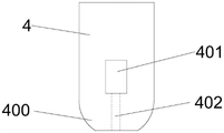
FIG. 3 is a schematic view of a reinforced concrete section at the bottom of a pier in the present invention;
FIG. 4 is a schematic structural view of an anti-buckling support of the present invention;
FIG. 5 is a cross-sectional view taken along line A-A of FIG. 4;
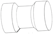
FIG. 6 is a schematic view of the connection of the upper and lower sleeves of the buckling restrained brace of the present invention;
FIG. 7 is a cross-sectional view of the upper sleeve of the anti-buckling support of the present invention;
FIG. 8 is a schematic diagram of an energy dissipation plate structure of the buckling restrained brace in the present invention;
FIG. 9 is a schematic view of the structure of the energy dissipation block of the buckling restrained brace in the present invention
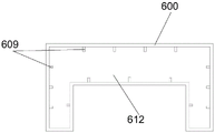
FIG. 10 is a schematic view of the inner structure of the lower sleeve of the buckling restrained brace in the present invention;
fig. 11 is a schematic structural diagram of a connection head of the buckling-restrained brace in the invention.
FIG. 12 is a schematic view of the angle of the anti-buckling support of the present invention;
FIG. 13 is a schematic view of a built-in energy consuming device of the present invention;
FIG. 14 is a schematic view of a concave steel plate in the internal energy dissipation device of the present invention;
FIG. 15 is a schematic view of a T-shaped steel plate in the internal energy dissipation device of the present invention;
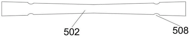
figure 16 is a schematic view of energy dissipating bars in the built-in energy dissipating device of the present invention;
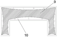
FIG. 17 is a schematic representation of the concrete in the core constraining zone of the sleeve of the present invention.
In the figure: 1-capping beam, 2-prestressed tendon, 3-bearing platform, 300-hemispherical groove, 4-segment pier, 400-hemispherical joint, 401-reserved hole, 402-T-shaped steel plate hole, 5-built-in energy dissipation device, 500-T-shaped steel plate, 501-concave steel plate, 502-energy dissipation rod, 503-through hole, 504-transverse stiffening rib, 505-fixing plate, 506-bolt hole, 507-compression spring, 508-annular groove, 509-concave connecting plate, 6-buckling-proof support, 600-upper sleeve, 601-lower sleeve, 602-upper energy dissipation plate, 603-lower energy dissipation plate, 604-energy dissipation block, 605-connecting head, 606-SMA rod, 607-circular through hole, 608-angle steel, 609-vertical stiffening rib, 610-connecting groove, 611-limiting rubber, 612-tuff concrete, 613-clamp, 614-backing plate, 615-rod hole, 616-strip-shaped groove, 617-connecting hole, 7-anchorage device, 8-connecting lug plate, 9-core area concrete and 10-non-core area concrete.
Detailed Description
The invention is further illustrated by the following figures and examples. Fig. 1 to 17 are drawings of embodiments, which are drawn in a simplified manner and are provided only for the purpose of clearly and concisely illustrating embodiments of the present invention. The following claims presented in the drawings are specific to embodiments of the invention and are not intended to limit the scope of the claimed invention. All other embodiments, which can be derived by a person skilled in the art from the embodiments given herein without making any creative effort, shall fall within the protection scope of the present invention.
In the description of the present invention, it is to be understood that the terms "upper", "lower", "inside", "outside", "left", "right", and the like, indicate orientations or positional relationships based on the orientations or positional relationships shown in the drawings, or the orientations or positional relationships that the products of the present invention are conventionally placed in use, or the orientations or positional relationships that are conventionally understood by those skilled in the art, and are used for convenience of describing the present invention and simplifying the description, but do not indicate or imply that the devices or elements referred to must have a specific orientation, be constructed in a specific orientation, and be operated, and thus, should not be construed as limiting the present invention.
The embodiment provides a double-column type self-resetting pier structure with an anti-buckling support, which comprises a capping beam 1, a bearing platform 3 and two groups of segmental pier bodies 4 positioned between the capping beam 1 and the bearing platform 3, wherein each group of segmental pier bodies 4 is formed by assembling multiple sections of reinforced concrete segments, are prefabricated for a factory and are connected with the capping beam 1 and the bearing platform 3 through unbonded prestressed ribs 2; a built-in energy dissipation device 5 is arranged at the position where each group of segmental pier bodies 4 is connected with the bearing platform 3, two buckling restrained braces 6 distributed in a herringbone shape are arranged between the two groups of segmental pier bodies 4, and each buckling restrained brace 6 comprises an energy dissipation restraining rod body and connectors 605 positioned at two ends of the rod body; the connector 605 is welded at the end part of the energy consumption restraining rod body, and the upper end and the lower end of the buckling restrained brace 6 are respectively connected with the bent cap 1 and the bearing platform 3 through the connectors 605; as shown in fig. 2, the positions of the upper surface of the bearing platform 3 corresponding to the two sets of segmental abutment bodies 4 are respectively provided with a hemispherical groove 300, the lower end surface of the reinforced concrete section at the bottom of each set of segmental abutment bodies 4 connected with the bearing platform 3 is provided with a hemispherical joint 400 matched with the hemispherical groove 300, the hemispherical joint 400 at the bottom of each set of segmental abutment bodies 4 is correspondingly embedded into the hemispherical groove 300 on the upper surface of the bearing platform 1, and the sectional dimensions of the hemispherical groove 300 and the hemispherical joint 400 can be determined according to actual conditions. Each group of segmental pier bodies 4 is connected with the capping beam 1 and the bearing platform 3 through a plurality of unbonded prestressed tendons 2, each unbonded prestressed tendon 2 straightly and unkinks and penetrates through the whole pier body main body, and two ends of each unbonded prestressed tendon are anchored in the bearing platform 3 and the capping beam 1 through an anchorage device 7 respectively; connecting lug plates 8 are correspondingly arranged in the middle of the bent cap 1 and on the bearing platform 3, and the buckling restrained brace 6 is connected with the corresponding connecting lug plates 8 through high-strength bolts.
According to the double-column self-resetting pier structure with the buckling restrained braces, as shown in fig. 13 to 15, the built-in energy dissipation device 5 comprises a T-shaped steel plate 500, a concave steel plate 501 and energy dissipation rods 502, a T-shaped head of the T-shaped steel plate 500 is arranged in the bearing platform 3, and free ends of vertical steel plates of the T-shaped steel plate 500 are inserted into grooves of the concave steel plate 501 and connected through the energy dissipation rods 502; as shown in fig. 3, a pre-reserved hole 401 matched with the outer contour width of the concave steel plate 501 is arranged in the reinforced concrete section where each group of segmental pier bodies 4 is connected with the bearing platform 3; as shown in fig. 13 and 14, a fixing plate 505 extending horizontally outward is disposed at a groove opening of the concave steel plate 501, a bolt hole 506 is disposed on the fixing plate 505, a plurality of through holes 503 with a diameter matched with that of the energy dissipation rod 502 are correspondingly disposed on two parallel steel plates on the side surface of the concave steel plate 501, the plurality of through holes 503 are distributed in a quincunx shape, a plurality of transverse stiffening ribs 504 are disposed near the through holes 503 of the concave steel plate, and two compression springs 507 are disposed at a groove portion of the concave steel plate 501; a concave connecting plate 509 is arranged at the end part of the vertical steel plate of the T-shaped steel plate 500, the width of the concave connecting plate 509 is matched with the width of the groove of the concave steel plate 501, the T-shaped steel plate 500 is embedded into the groove of the concave steel plate 501 through the concave connecting plate 509 at the end part, the end parts of two parallel plates of the concave connecting plate 509 are correspondingly connected with two compression springs 507, and through holes 503 matched with the diameter of the energy dissipation rod 502 are correspondingly arranged on the two parallel plate surfaces of the concave connecting plate 509; as shown in fig. 15, the energy dissipation rods 502 are made of mild steel with low yield point, are shaped like an hourglass with an arc-shaped surface in the middle, and are symmetrically provided with annular grooves 508 at two ends, and each energy dissipation rod 502 is inserted into a through hole 503 corresponding to the T-shaped steel plate 500 and the concave steel plate 501 to connect the two; as shown in fig. 1, the concave steel plate 501 is placed in the reserved hole 401, the fixing plate 505 is fixedly connected with the lower end face of the reserved hole 401 through a high-strength bolt, the T-shaped head of the T-shaped steel plate 500 is provided with a position 300-600 mm deep from the bearing platform 3, the vertical steel plate extends into the groove of the concave steel plate 501 along the T-shaped steel plate hole 402, and the height of the T-shaped steel plate 500 extending into the segmental pier body 4 is 500-1000 mm; and after the built-in energy dissipation device 5 is installed, high-grade plain concrete is filled in the reserved hole 401.
In the earthquake process, the pier column is separated from the bearing platform, the pier column enters a swinging state, the concave steel plate 500 and the T-shaped steel plate 501 are driven to move away from each other relatively, and the energy dissipation rod 502 is sheared and yielded to consume energy. The energy dissipation rods 502 are hourglass-shaped, in the first shear yielding stage, the middle section of each energy dissipation rod is firstly subjected to yielding fracture due to the fact that the shear surface is small, in the second stage, the annular grooves 508 at the two ends of each energy dissipation rod are subjected to shear failure due to stress concentration, in the third stage, the energy dissipation rods are broken and lose effect, and seismic energy is consumed only through the spring force generated when the T-shaped steel plates 501 extrude the compression springs 507. Therefore, the multi-stage energy consumption of the built-in energy consumption device can be realized in a grading way. The built-in energy dissipation device can consume earthquake energy through the energy dissipation rod and the compression spring, is excellent in energy dissipation and convenient and fast to install, and the energy dissipation rod 502 can be replaced by chiseling plain concrete filled in the reserved hole 401 after the earthquake.
During an earthquake, the built-in energy consumption device can consume energy as follows:

in the formula: f1Is the maximum stress, X, sustained in the first stage1For the first-stage displacement of the spring, τbTo allow shear stress, d1Is the diameter of the middle shear plane of the energy dissipation rod, d2The diameters of the annular grooves at the two ends of the energy dissipation rod are shown, G is the shearing elastic modulus of the spring, D is the wire diameter of the spring, n is the reasonable number of turns of the spring, D is the central diameter of the spring, and F2Is the maximum stress, X, sustained in the first stage2For the first stage displacement of the spring, F1Maximum stress to be withstood by the third stage, X3For the third stage displacement of the spring, W is the energy consumed by the device.
In an embodiment of the double-column self-resetting pier structure with the buckling restrained brace, as shown in fig. 4 to 12, the energy dissipation restraining rod body includes a square sleeve structure formed by connecting an upper sleeve 600 and a lower sleeve 601 through an SMA rod 606, and an upper energy dissipation plate 602, a lower energy dissipation plate 603 and an energy dissipation block 604 which are located in the square sleeve structure; the upper sleeve 600 and the lower sleeve 601 are connected through a plurality of SMA rods 606 after being butted, the upper sleeve 600 and the lower sleeve 601 both adopt concave steel pipes, and tuff concrete 612 is filled in the pipe bodies of the upper sleeve 600 and the lower sleeve 601; the inner walls of the groove-shaped steel pipes of the upper sleeve 600 and the lower sleeve 601 are provided with a plurality of vertical stiffening ribs 609, and the top surface of the upper sleeve 600 and the bottom surface of the lower sleeve 601 are correspondingly provided with a plurality of rows of SMA rod orifices 615; the SMA rod 606 penetrates through the two ends of an SMA rod hole 615 corresponding to the upper sleeve 600 and the lower sleeve 601 and is fixed on the outer surface of the sleeve through a clamp 613 and a backing plate 614 respectively, the SMA rod 606 keeps stable fixation and clamping on the two ends of the SMA rod 606 through the clamp 613, so that the SMA rod can be convenient for tightening operation after installation, meanwhile, the stable fixed tightening state of the SMA rod can be ensured, the upper sleeve and the lower sleeve are tightly connected, and the backing plate 614 is arranged to share stress so as to prevent the sleeve from being damaged due to overlarge local stress; the size of the side plate of the lower sleeve 601 is larger than that of the side plate of the upper sleeve 600, the upper surface of the side plate of the lower sleeve 601 is provided with a connecting groove 610 matched with the size of the side plate of the upper sleeve 600, the bottom of an inner groove of the connecting groove 610 is provided with a limiting rubber 611, and the butt joint end of the side plate of the upper sleeve 600 is inserted into the connecting groove 610 of the side plate of the lower sleeve 601 and a deformation gap is reserved; the limiting rubber 611 can avoid the extrusion damage of the upper sleeve and the lower sleeve caused by overlarge restoring force of the SMA rod 606, and can also isolate external aggressive media from entering the sleeves, so that the buckling restrained brace is prevented from being corroded; the outer surfaces of the upper sleeve 600 and the lower sleeve 601 are provided with a plurality of strip-shaped grooves 616, each strip-shaped groove 616 is perpendicular to the length direction of the sleeve, and the aperture of a circular through hole 607 corresponding to the strip-shaped groove 616 and the diameter of the energy dissipation block 604 are reduced compared with the diameters of other positions, so that the stress concentration phenomenon is generated at the strip-shaped grooves 616, the positioning and buckling of a component are realized, and the self-resetting system of the SMA rod can play a role more easily; the energy dissipation plate in the buckling-restrained brace is stressed to buckle the outer drum under the action of an earthquake to drive the upper sleeve and the lower sleeve to move away from each other relatively, so that the SMA rod 606 stretches to generate a tensile force, after the earthquake is finished, the upper sleeve and the lower sleeve are relatively close to each other through the self restoring force of the SMA rod 606, the component returns to the original position, the self-resetting effect is achieved, and the buckling-restrained brace can work normally after being shaken.
According to the double-column self-resetting pier structure with the buckling restrained brace, as shown in fig. 5 and 6, one side of the upper energy dissipation plate 602 is connected to the inner side of the top plate of the upper sleeve 600, one side of the lower energy dissipation plate 603 is connected to the inner side of the bottom plate of the lower sleeve 601, the other sides of the upper energy dissipation plate 602 and the lower energy dissipation plate 603 are overlapped, and the overlapping areas are connected through the energy dissipation blocks 604. The upper energy consumption plate 602, the lower energy consumption plate 603 and the energy consumption block 604 are all made of aluminum alloy materials; a deformation gap of 2-5 mm is reserved between the upper energy consumption plate 602 and the lower energy consumption plate 603; the yield strength of the energy consumption block 604 is lower than that of the upper energy consumption plate 602 and the lower energy consumption plate 603, and the grading energy consumption effect is realized through the difference of the yield displacement and the yield strength of the two energy consumption plates; the upper energy dissipation plate 602 and the lower energy dissipation plate 603 are staggered and in a straight-line lap joint, a row of circular through holes 607 are correspondingly formed in the lap joint area, and the distance between every two adjacent circular through holes 607 is 300-1000 mm; the energy dissipation blocks 604 are cylindrical structures with the diameters matched with the diameters of the circular through holes 607, one energy dissipation block 604 is correspondingly inserted into each circular through hole 607, and the upper energy dissipation plate 602 is connected with the lower energy dissipation plate 603 through the energy dissipation blocks 604; as shown in fig. 10, the upper energy dissipation plate 602 and the lower energy dissipation plate 603 are respectively connected to the upper sleeve 600 and the lower sleeve 601 through a plurality of sections of angle steel 608, a plurality of connection holes 617 are equidistantly formed in the angle steel 608, each energy dissipation plate is correspondingly provided with a connection hole 617, and the energy dissipation plate is connected to the corresponding sleeve through the angle steel 608 at both sides.
The buckling-restrained brace 6 consumes seismic energy through the energy consumption blocks or the energy consumption plates, wherein the energy consumption blocks 604 consume energy through shearing yield deformation, the energy consumption plates generate plastic deformation energy consumption through axial tension and compression yielding, and the yield displacement of the energy consumption blocks 604 is far smaller than that of the energy consumption plates, so that grading energy consumption can be realized through the difference of the yield displacement and the yield strength of the energy consumption blocks and the energy consumption plates. Under the action of small shock, the upper energy dissipation plate and the lower energy dissipation plate are in an elastic stage, and due to the fact that the yield strength of the energy dissipation blocks 604 is low, the energy dissipation blocks are subjected to shear deformation through relative displacement generated by axial tension and compression, and then yield energy dissipation is achieved. Under the action of a large earthquake, the energy consumption block 604 firstly reaches the yield strength, the energy consumption plate is buckled and destabilized later to enter the yield state, and the energy consumption block 604 and the upper and lower energy consumption plates work together to realize the common energy consumption.
Because the sleeve adopts the special-shaped steel pipe concrete column, the axial force which can be born by the sleeve in the earthquake process is not calculated in a specific formula. The outer steel tube of the special-shaped steel tube concrete has the functions of longitudinal ribs and stirrups, the vertical stiffening ribs have the functions of longitudinal ribs and tie ribs, and the concrete in the core area is restrained by the outer steel tube. Therefore, according to the Mander constraint concrete model, an equivalent lateral constraint stress method is adopted, the structure of the outer steel pipe and the stiffening rib is comprehensively considered, and the division of the core area and the non-core area of the cross-section concrete is shown in figure 17. The boundary of the non-constrained region of the core constrained region can be approximately regarded as a parabola, and the geometric equation of the parabola can be obtained according to the graph as follows:

according to the Mander constraint concrete model, assuming that the boundary between the core constraint area and the non-core constraint area is an initial tangent angle theta equal to 45 degrees, the equation is as follows:

from the above equation, one can obtain:


in the formula: a. thersIs a non-core constrained area, ArAs a core constraint area, keThe reduction factor is equivalent constraint.
In the concrete-filled steel tube structure-theory and practice, the calculation formula of the bearing capacity of the single-cavity concrete-filled steel tube column is as follows:
Nu=Ascfscy
Asc=As+Ac
fscy=(1.18+0.85ξ)fck

in the formula: a. thesIs the cross-sectional area of the steel pipe, AcIs the core concrete cross-sectional area, xi is the constraint effect coefficient, fckIs the compressive strength of concrete, fyThe yield strength of the steel.
However, the formula is not suitable for calculating the bearing capacity of the special-shaped concrete-filled steel tube column, so that the bearing capacity of the special-shaped concrete-filled steel tube column is corrected by introducing a coefficient delta, and the formula is obtained by nonlinear fitting analysis of experimental data of the special-shaped concrete-filled steel tube column according to the text of research on axial compression performance of the rectangular multi-cavity concrete column:
Nu=Ascδfscy
δ=(-0.0338x2+0.2699x+1.641)ke
in the formula: n is a radical ofuThe bearing capacity of the concrete of the special-shaped steel pipe is shown, and x is the number of the cavities.
The energy dissipation plate in the buckling-restrained brace is used as a slender pressure bar, the energy dissipation block is driven to generate shearing damage under the action of an earthquake, the energy dissipation plate exceeds the material proportion limit to generate buckling instability along with the increase of earthquake motion, and the shearing damage force of the energy dissipation block and the critical force of the energy dissipation plate can be obtained according to the following formula:


in the formula: f is shear force of energy-consuming block, τbAllowable stress for energy-consuming block, n1、n2Number of energy-consuming blocks, d1、 d2The shear plane diameter of the energy dissipation block, F the critical force of the energy dissipation plate, E the elastic modulus, and l the length of the energy dissipation plateAnd b and h are the cross section sizes of the energy dissipation plate.
The invention is further explained by combining a specific construction process, and the construction process of the double-column type self-resetting pier structure specifically comprises the following steps:
the method comprises the following steps: prefabricating a segment pier body and a cover beam. And (4) blanking and binding the reinforcing steel bars of the pier body 4 and the bent cap 1 according to a design drawing, and manufacturing the reinforced concrete section of the pier body of the pier and the reinforcing cage of the bent cap 1. And (3) processing and installing a wood template according to the section size of each component, and reserving a prestressed rib hole channel, an anchoring groove, a T-shaped steel plate hole channel 402 and a reserved hole 401 of the pier body and the bent cap of the pier. And finally, concrete pouring is carried out on each component, the components are compacted through vibration and are maintained through watering, and the maintenance time can be adjusted according to the actual situation and is not less than 7 d.
Step two: and (5) constructing a bearing platform. Leveling a field, measuring and setting off, excavating a foundation pit according to a construction scheme, chiseling a pier pile head and detecting the quality of a pile body after excavating to a designed depth. Binding 3 reinforcing steel bars of the bearing platform after the detection is qualified, processing and manufacturing 3 wooden templates of the bearing platform, simultaneously embedding an unbonded prestressed reinforcement anchor head and a T-shaped steel plate 500, erecting an unbonded prestressed reinforcement 2 and the T-shaped steel plate 500, finally pouring concrete, vibrating to be dense, and watering, maintaining and forming.
Step three: and assembling the prefabricated double-column pier. And after the section pier body, the bent cap 1 and the bearing platform 3 are maintained to the designed strength, the section pier body, the bent cap 1 and the bearing platform are assembled through the unbonded prestressed tendons 2. Before assembling, each section contact surface of the pier body of the pier is manually polished, so that no protrusion or burr is formed on the surface, and floating dust on the contact surface between the sections is cleaned. Then, cement paste or epoxy resin glue with the thickness of 2 mm-5 mm is uniformly coated on the joint part, so that shaking caused by manufacturing errors of two sections of contact surfaces is eliminated or a waterproof effect is achieved.
Step four: and tensioning the prestressed tendons. The tensioning of the unbonded prestressed tendon 2 of the pier adopts a post-tensioning method, the tensioning mode is that tensioning is carried out through one end, the position of the bearing platform 3 is an anchoring end, the position of the coping 1 is a tensioning end, a clamping piece type anchorage device 7 is selected for anchoring, symmetrical tensioning is carried out on the pier body, and after tensioning is completed, micro-expansion concrete is adopted to fill an anchoring groove of the coping 1.
Step five: and installing a built-in energy consumption device. The concave steel plate 501 is fixed on the lower end face of the reserved hole 401 through a high-strength bolt, then the energy dissipation rod 502 is inserted into a quincunx through hole in the side face of the concave steel plate 501 to connect the concave steel plate 501 and the T-shaped steel plate 500, then epoxy resin glue is coated on the outer surface of the concave steel plate 501 to isolate oxygen and water in the external environment, prevent external substances from invading the energy dissipation device to cause corrosion and influence the energy dissipation function of the energy dissipation device, and finally high-grade plain concrete is adopted to fill the reserved hole 401.
Step six: and (5) installing a buckling restrained brace. The buckling-restrained brace 6 is manufactured and installed in a factory, then transported to a construction site, connected with connecting lug plates 8 arranged on the upper surface of the bearing platform 3 and in the middle of the cover beam 1 through high-strength bolts and arranged between pier columns of the double-column pier in a herringbone mode. And finishing the construction of the pier.
While the present invention has been described with reference to the embodiments shown in the drawings, the present invention is not limited to the embodiments, which are illustrative and not restrictive, and it will be apparent to those skilled in the art that various changes and modifications can be made therein without departing from the spirit and scope of the invention as defined in the appended claims.
Claims (10)
1. The utility model provides a take double column formula of buckling restrained brace from restoring to throne pier structure which characterized in that: the pier structure comprises a capping beam (1), a bearing platform (3) and two groups of segmental pier bodies (4) positioned between the capping beam (1) and the bearing platform (3), wherein each group of segmental pier bodies (4) is formed by assembling multiple sections of reinforced concrete sections and is connected with the capping beam (1) and the bearing platform (3) through unbonded prestressed ribs (2); a built-in energy dissipation device (5) is arranged at the position where each group of segmental pier bodies (4) is connected with the bearing platform (3), each built-in energy dissipation device (5) comprises a T-shaped steel plate (500), a concave steel plate (501) and energy dissipation rods (502), the T-shaped head of each T-shaped steel plate (500) extends into the bearing platform (3), the free end of each vertical steel plate is inserted into a groove of each concave steel plate (501) and is connected with the corresponding energy dissipation rod (502); two buckling restrained braces (6) distributed in a herringbone shape are arranged between the two groups of segment pier bodies (4), each buckling restrained brace (6) comprises an energy consumption restraining rod body and connectors (605) positioned at two ends of the rod body, and the upper end and the lower end of each buckling restrained brace (6) are respectively connected with the cover beam (1) and the bearing platform (3) through the connectors (605); the energy consumption restraining rod body comprises a square sleeve structure formed by connecting an upper sleeve (600) and a lower sleeve (601) through an SMA rod (606), and an upper energy consumption plate (602), a lower energy consumption plate (603) and an energy consumption block (604) which are positioned in the square sleeve structure; the upper sleeve (600) and the lower sleeve (601) are both made of concave steel pipes, tuff concrete (612) is filled in a pipe body of the upper sleeve (600) and the lower sleeve (601) are connected through a plurality of SMA rods (606) after being butted, one side of the upper energy dissipation plate (602) is connected to the inner side of a top plate of the upper sleeve (600), one side of the lower energy dissipation plate (603) is connected to the inner side of a bottom plate of the lower sleeve (601), the other sides of the upper energy dissipation plate (602) and the lower energy dissipation plate (603) are overlapped, and overlapping areas are connected through energy dissipation blocks (604).
2. The double-column type self-resetting pier structure with the buckling restrained brace, according to claim 1, is characterized in that: the upper surface of the bearing platform (3) is correspondingly connected with the positions of the two groups of segmental pier bodies (4) and is respectively provided with a hemispherical groove (300), the lower end surface of the reinforced concrete section at the bottom, connected with the bearing platform (3), of each group of segmental pier bodies (4) is provided with a hemispherical joint (400) matched with the hemispherical groove (300), and the hemispherical joint (400) at the bottom of each group of segmental pier bodies (4) is correspondingly embedded into the hemispherical groove (300) at the upper surface of the bearing platform (1).
3. The double-column type self-resetting pier structure with the buckling restrained braces according to claim 1 or 2, wherein: the upper energy dissipation plate (602) and the lower energy dissipation plate (603) are staggered and in a straight-line-shaped lap joint, a row of circular through holes (607) are correspondingly formed in the lap joint area, and the distance between every two adjacent circular through holes (607) is 300-1000 mm; the energy dissipation blocks (604) are of cylindrical structures, the diameters of the energy dissipation blocks are matched with the diameters of the circular through holes (607), one energy dissipation block (604) is correspondingly inserted into each circular through hole (607), and the upper energy dissipation plate (602) is connected with the lower energy dissipation plate (603) through the energy dissipation block (604).
4. The double-column type self-resetting pier structure with the buckling restrained braces according to claim 1 or 2, wherein: a reserved hole (401) matched with the outer contour width of the concave steel plate (501) is formed in a reinforced concrete section of each group of segmental pier bodies (4) connected with the bearing platform (3), a fixing plate (505) extending outwards and horizontally is arranged at a groove opening of the concave steel plate (501), a bolt hole (506) is formed in the fixing plate (505), the concave steel plate (501) is arranged in the reserved hole (401), the fixing plate (505) is fixedly connected with the lower end face of the reserved hole (401) through a high-strength bolt, and a T-shaped steel plate hole channel (402) is arranged below the reserved hole (401); the T-shaped head of the T-shaped steel plate (500) is internally provided with a position 300-600 mm deep in the bearing platform (3), the vertical steel plate extends into a groove of the concave steel plate (501) along the T-shaped steel plate pore passage (402), and the height of the T-shaped steel plate (500) extending into the segmental pier body (4) is 500-1000 mm; and after the built-in energy consumption device (5) is installed, plain concrete is filled in the reserved hole (401).
5. The double-column type self-resetting pier structure with the buckling restrained braces according to claim 1 or 2, wherein: a plurality of through holes (503) with the diameter matched with that of the energy dissipation rod (502) are correspondingly formed in two parallel steel plates on the side surface of the concave steel plate (501), the through holes (503) are distributed in a quincunx shape, a plurality of transverse stiffening ribs (504) are arranged near the through holes (503), and a compression spring (507) is arranged at the groove part of the concave steel plate (501); a concave connecting plate (509) is arranged at the end part of the vertical steel plate of the T-shaped steel plate (500), the T-shaped steel plate (500) is embedded into the groove of the concave steel plate (501) through the concave connecting plate (509) at the end part, the end parts of two parallel plates of the concave connecting plate (509) are connected with a compression spring (507), and through holes (503) matched with the diameter of the energy dissipation rod (502) are correspondingly arranged on two parallel plate surfaces of the concave connecting plate (509); the energy dissipation rods (502) are made of mild steel with low yield point, are hourglass-shaped and are provided with arc-shaped surfaces in the middle, annular grooves (508) are symmetrically formed in the two ends of each energy dissipation rod, and each energy dissipation rod (502) is inserted into a through hole (503) corresponding to the T-shaped steel plate (500) and the concave steel plate (501) to connect the energy dissipation rods and the concave steel plate.
6. The double-column type self-resetting pier structure with the buckling restrained braces according to claim 1 or 2, wherein: the upper energy consumption plate (602), the lower energy consumption plate (603) and the energy consumption block (604) are all made of aluminum alloy materials; a deformation gap of 2-5 mm is reserved between the upper energy consumption plate (602) and the lower energy consumption plate (603); the yield strength of the energy consumption block (604) is lower than that of the upper energy consumption plate (602) and the lower energy consumption plate (603); the upper energy dissipation plate (602) and the lower energy dissipation plate (603) are respectively connected with the upper sleeve (600) and the lower sleeve (601) through a plurality of sections of angle steel (608), a plurality of connecting holes (617) are formed in the angle steel (608) at equal intervals, and each energy dissipation plate is correspondingly provided with a connecting hole (617); the two sides of each energy dissipation plate are respectively connected with an angle steel (608) and are connected with the corresponding sleeves through the angle steels (608) on the two sides.
7. The double-column type self-resetting pier structure with the buckling restrained braces according to claim 1 or 2, wherein: each group of segmental pier bodies (4) is connected with the capping beam (1) and the bearing platform (3) through a plurality of unbonded prestressed tendons (2), each unbonded prestressed tendon (2) straightly penetrates through the whole pier body without bending, and two ends of each unbonded prestressed tendon are anchored in the bearing platform (3) and the capping beam (1) through an anchorage device (7) respectively; the middle part of the bent cap (1) and the bearing platform (3) are correspondingly provided with connecting lug plates (8), and the buckling-restrained brace (6) is connected with the corresponding connecting lug plates (8) through high-strength bolts.
8. The double-column type self-resetting pier structure with the buckling restrained brace, according to claim 3, is characterized in that: the size of a side plate of the lower sleeve (601) is larger than that of a side plate of the upper sleeve (600), a connecting groove (610) matched with the size of the side plate of the upper sleeve (600) is formed in the upper surface of the side plate of the lower sleeve (601), limiting rubber (611) is arranged at the bottom of an inner groove of the connecting groove (610), and the butt joint end of the side plate of the upper sleeve (600) is inserted into the connecting groove (610) of the side plate of the lower sleeve (601) and a deformation gap is reserved; the inner walls of the groove-shaped steel pipes of the upper sleeve (600) and the lower sleeve (601) are provided with a plurality of vertical stiffening ribs (609), the top surface of the upper sleeve (600) and the bottom surface of the lower sleeve (601) are correspondingly provided with at least one row of SMA rod hole channels (615), and the SMA rods (606) penetrate through the two ends of the SMA rod hole channels (615) corresponding to the upper sleeve (600) and the lower sleeve (601) and are fixed on the outer surface of the sleeves through clamps (613) and backing plates (614) respectively; the outer surfaces of the upper sleeve (600) and the lower sleeve (601) are provided with a plurality of strip-shaped grooves (616), each strip-shaped groove (616) is perpendicular to the length direction of the sleeve, and the aperture of the circular through hole (607) corresponding to the strip-shaped groove (616) and the diameter of the energy dissipation block (604) are reduced compared with other positions.
9. A construction method of the double post type self-restoration pier structure with the buckling restrained braces as recited in any one of claims 1 to 8, characterized by comprising the following specific steps:
the method comprises the following steps: prefabricated segment pier body and bent cap. Carrying out steel bar blanking and binding work on the bent cap and the reinforced concrete section of the segmental pier body according to a design drawing, and finishing the manufacture of the reinforced concrete section of the pier body of the pier and the steel bar cage of the bent cap; and reserving the prestressed tendon pore channel, the anchoring groove, the T-shaped steel plate pore channel and the reserved hole when manufacturing the bent cap and the reinforced concrete section, and finally performing concrete pouring on each component, vibrating for compacting and watering for maintenance, wherein the maintenance time is not less than 7 d.
Step two: and (5) constructing a bearing platform. Leveling a field, measuring and setting out, excavating a foundation pit according to a design drawing, chiseling a pier pile head and detecting the quality of a pile body after excavating to a design depth; and binding a bearing platform steel bar after the detection is qualified, processing and manufacturing a bearing platform wood template, simultaneously embedding an anchor head of the unbonded prestressed bar and a T-shaped steel plate, erecting the unbonded prestressed bar and the T-shaped steel plate, finally pouring bearing platform concrete, vibrating and compacting, and watering, curing and forming.
Step three: and (5) assembling the prefabricated double-column pier. And (3) after the prefabricated section pier body and the capping beam in the step one and the constructed and bearing platform in the step two are maintained to the designed strength, assembling the prefabricated section pier body and the capping beam through unbonded prestressed tendons.
Step four: and tensioning the prestressed tendons. The tensioning of the unbonded prestressed tendon of the pier adopts a post-tensioning method, the tensioning mode is that tensioning is carried out through one end, the bearing platform position of the prestressed tendon is an anchoring end, the position of the coping is a tensioning end, a clamping piece type anchorage device is selected for anchoring, symmetrical tensioning is carried out on the pier body, and after tensioning is completed, micro-expansion concrete is adopted to fill the capping beam anchoring groove.
Step five: and installing a built-in energy consumption device. Fixing the concave steel plate on the lower end face of the reserved hole through a high-strength bolt, then inserting an energy dissipation rod into a through hole in the side face of the concave steel plate to connect the concave steel plate with the T-shaped steel plate, then coating epoxy resin glue on the outer surface of the concave steel plate, and finally filling the reserved hole with high-grade plain concrete.
Step six: and (5) installing a buckling restrained brace. The buckling-restrained brace is transported to a construction site after being manufactured and installed in a factory, is connected with connecting lug plates arranged on the upper surface of the bearing platform and the middle part of the capping beam through high-strength bolts and is arranged between pier columns of the double-column pier in a herringbone mode, and construction of the pier is completed.
10. The construction method of the double post type self-resetting pier structure with the buckling restrained braces according to claim 9, wherein in the second step: before assembling, each section contact surface of the pier body is manually polished, floating dust of the contact surface between the sections is cleaned, and then cement paste or epoxy resin glue with the thickness of 2 mm-5 mm is uniformly coated on the joint position.
Priority Applications (1)
| Application Number | Priority Date | Filing Date | Title |
|---|---|---|---|
| CN202210331665.5A CN114622481B (en) | 2022-03-31 | 2022-03-31 | Double-column type self-resetting pier structure with buckling restrained brace and construction method thereof |
Applications Claiming Priority (1)
| Application Number | Priority Date | Filing Date | Title |
|---|---|---|---|
| CN202210331665.5A CN114622481B (en) | 2022-03-31 | 2022-03-31 | Double-column type self-resetting pier structure with buckling restrained brace and construction method thereof |
Publications (2)
| Publication Number | Publication Date |
|---|---|
| CN114622481A true CN114622481A (en) | 2022-06-14 |
| CN114622481B CN114622481B (en) | 2023-05-05 |
Family
ID=81905158
Family Applications (1)
| Application Number | Title | Priority Date | Filing Date |
|---|---|---|---|
| CN202210331665.5A Active CN114622481B (en) | 2022-03-31 | 2022-03-31 | Double-column type self-resetting pier structure with buckling restrained brace and construction method thereof |
Country Status (1)
| Country | Link |
|---|---|
| CN (1) | CN114622481B (en) |
Cited By (3)
| Publication number | Priority date | Publication date | Assignee | Title |
|---|---|---|---|---|
| CN109403493A (en) * | 2018-11-22 | 2019-03-01 | 华中科技大学 | Have displacement equations type double shear knife supporting damping device system and vibration damping efficiency estimation method |
| CN115559287A (en) * | 2022-11-16 | 2023-01-03 | 中国船舶重工集团国际工程有限公司 | Buckling-restrained supporting device for offshore suction bucket type jacket and jacket structure |
| CN115749030A (en) * | 2022-11-28 | 2023-03-07 | 西安建筑科技大学 | Self-resetting supporting device with energy consumption bar |
Citations (16)
| Publication number | Priority date | Publication date | Assignee | Title |
|---|---|---|---|---|
| US20010000840A1 (en) * | 1999-06-30 | 2001-05-10 | Toru Takeuchi | Buckling restrained braces and damping steel structures |
| US20110239551A1 (en) * | 2010-03-31 | 2011-10-06 | National University Corporation Nagoya Institute Of Technology | Self-centering compact damper unit applicable to structures for seismic energy dissipation |
| US20130042546A1 (en) * | 2011-08-18 | 2013-02-21 | Larry Richard Bowlus | Seismic base isloation and energy dissipation device |
| CN106499077A (en) * | 2016-09-20 | 2017-03-15 | 北京工业大学 | Metal-rubber damper with limitation locking function and anti-buckling support combinations energy-dissipating device |
| CN206570676U (en) * | 2016-12-15 | 2017-10-20 | 同济大学 | A kind of queen post Self-resetting power consumption bridge pier of the replaceable steel coupling beam of band |
| KR20180046558A (en) * | 2016-10-28 | 2018-05-09 | 성균관대학교산학협력단 | Damper for earthquake proof of structure |
| CN109371818A (en) * | 2018-11-27 | 2019-02-22 | 东南大学 | A kind of anti-seismic prefabricated assembly bridge pier and its construction method |
| CN109853773A (en) * | 2019-04-12 | 2019-06-07 | 中国地震局工程力学研究所 | Multistage-compound anti-buckling support of multistage energy consumption and installation method |
| CN110468993A (en) * | 2019-07-26 | 2019-11-19 | 北京工业大学 | A kind of assembled cold-rolled forming section wall-plate-column shock absorbing structural system with lead shearing type damper |
| CN112030718A (en) * | 2020-08-06 | 2020-12-04 | 同济大学 | Multistage swing system for quickly connecting prefabricated assembled pier and bearing platform |
| CN112502035A (en) * | 2020-12-08 | 2021-03-16 | 防灾科技学院 | Assembled bridge double-column pier containing triple energy dissipation system |
| CN112962807A (en) * | 2021-01-21 | 2021-06-15 | 北京交通大学 | Friction type self-resetting cast-in-situ beam column node |
| CN113481833A (en) * | 2021-07-23 | 2021-10-08 | 北京工业大学 | Prefabricated assembly type swing pier structure system with additional energy dissipation support or self-resetting energy dissipation support |
| CN113737988A (en) * | 2021-09-07 | 2021-12-03 | 江苏海洋大学 | Vertical prestress assembly energy dissipation coupled wall structure and assembly method thereof |
| CN113944098A (en) * | 2021-10-11 | 2022-01-18 | 北京建筑大学 | Take two pier stud structures of assembled from restoring to throne of energy dissipation steel sheet |
| CN113982343A (en) * | 2021-08-13 | 2022-01-28 | 重庆大学 | Novel assembled area SMA is from restoring to throne bucking restraint support device |
-
2022
- 2022-03-31 CN CN202210331665.5A patent/CN114622481B/en active Active
Patent Citations (16)
| Publication number | Priority date | Publication date | Assignee | Title |
|---|---|---|---|---|
| US20010000840A1 (en) * | 1999-06-30 | 2001-05-10 | Toru Takeuchi | Buckling restrained braces and damping steel structures |
| US20110239551A1 (en) * | 2010-03-31 | 2011-10-06 | National University Corporation Nagoya Institute Of Technology | Self-centering compact damper unit applicable to structures for seismic energy dissipation |
| US20130042546A1 (en) * | 2011-08-18 | 2013-02-21 | Larry Richard Bowlus | Seismic base isloation and energy dissipation device |
| CN106499077A (en) * | 2016-09-20 | 2017-03-15 | 北京工业大学 | Metal-rubber damper with limitation locking function and anti-buckling support combinations energy-dissipating device |
| KR20180046558A (en) * | 2016-10-28 | 2018-05-09 | 성균관대학교산학협력단 | Damper for earthquake proof of structure |
| CN206570676U (en) * | 2016-12-15 | 2017-10-20 | 同济大学 | A kind of queen post Self-resetting power consumption bridge pier of the replaceable steel coupling beam of band |
| CN109371818A (en) * | 2018-11-27 | 2019-02-22 | 东南大学 | A kind of anti-seismic prefabricated assembly bridge pier and its construction method |
| CN109853773A (en) * | 2019-04-12 | 2019-06-07 | 中国地震局工程力学研究所 | Multistage-compound anti-buckling support of multistage energy consumption and installation method |
| CN110468993A (en) * | 2019-07-26 | 2019-11-19 | 北京工业大学 | A kind of assembled cold-rolled forming section wall-plate-column shock absorbing structural system with lead shearing type damper |
| CN112030718A (en) * | 2020-08-06 | 2020-12-04 | 同济大学 | Multistage swing system for quickly connecting prefabricated assembled pier and bearing platform |
| CN112502035A (en) * | 2020-12-08 | 2021-03-16 | 防灾科技学院 | Assembled bridge double-column pier containing triple energy dissipation system |
| CN112962807A (en) * | 2021-01-21 | 2021-06-15 | 北京交通大学 | Friction type self-resetting cast-in-situ beam column node |
| CN113481833A (en) * | 2021-07-23 | 2021-10-08 | 北京工业大学 | Prefabricated assembly type swing pier structure system with additional energy dissipation support or self-resetting energy dissipation support |
| CN113982343A (en) * | 2021-08-13 | 2022-01-28 | 重庆大学 | Novel assembled area SMA is from restoring to throne bucking restraint support device |
| CN113737988A (en) * | 2021-09-07 | 2021-12-03 | 江苏海洋大学 | Vertical prestress assembly energy dissipation coupled wall structure and assembly method thereof |
| CN113944098A (en) * | 2021-10-11 | 2022-01-18 | 北京建筑大学 | Take two pier stud structures of assembled from restoring to throne of energy dissipation steel sheet |
Cited By (5)
| Publication number | Priority date | Publication date | Assignee | Title |
|---|---|---|---|---|
| CN109403493A (en) * | 2018-11-22 | 2019-03-01 | 华中科技大学 | Have displacement equations type double shear knife supporting damping device system and vibration damping efficiency estimation method |
| CN109403493B (en) * | 2018-11-22 | 2023-07-25 | 华中科技大学 | Double-shear supporting damper system with displacement amplification and vibration reduction efficiency evaluation method |
| CN115559287A (en) * | 2022-11-16 | 2023-01-03 | 中国船舶重工集团国际工程有限公司 | Buckling-restrained supporting device for offshore suction bucket type jacket and jacket structure |
| CN115749030A (en) * | 2022-11-28 | 2023-03-07 | 西安建筑科技大学 | Self-resetting supporting device with energy consumption bar |
| CN115749030B (en) * | 2022-11-28 | 2024-04-09 | 西安建筑科技大学 | Self-resetting supporting device with energy consumption rod |
Also Published As
| Publication number | Publication date |
|---|---|
| CN114622481B (en) | 2023-05-05 |
Similar Documents
| Publication | Publication Date | Title |
|---|---|---|
| CN106401018B (en) | A kind of assembled self-resetting swinging steel plate wall structural system | |
| CN114622481A (en) | Double-column type self-resetting pier structure with buckling-restrained brace and construction method thereof | |
| WO2019149270A1 (en) | Assembled pier for mixed reinforcement of normal steel rebar and finished threaded steel bar | |
| CA2314218C (en) | Tension and compression members for erecting structures | |
| JP2007247401A (en) | Elastic fiber reinforced composite structural member | |
| CN111962386A (en) | Energy-dissipation and shock-absorption type self-resetting prefabricated segment assembled pier structure and construction method thereof | |
| WO1997028327A9 (en) | Modular fiber-reinforced composite structural member | |
| CN112853933B (en) | Segment prefabricated assembled concrete-filled steel tube pier with restorable function | |
| CN110468691B (en) | Replaceable assembled concrete anti-swing pier system after disaster | |
| CN108867341B (en) | GFRP pipe-concrete-profile steel combined column base joint and construction method thereof | |
| CN110777661A (en) | Flange connection prefabricated assembly pier structure and construction method thereof | |
| CN206267356U (en) | A kind of assembled self-resetting swinging steel plate wall structural system | |
| CN111455834A (en) | Self-resetting prefabricated assembled pier and construction method thereof | |
| CN209907572U (en) | Self-resetting precast beam column anti-seismic node structure | |
| CN210368609U (en) | Self-resetting prefabricated assembled pier | |
| CN111455833A (en) | Self-resetting prefabricated assembled pier and construction method thereof | |
| CN111155643A (en) | Assembly type mixed frame structure and construction method | |
| CN210369312U (en) | Steel column base connection structure | |
| CN111074756A (en) | Damping and energy-consuming assembled type swing pier component and construction method thereof | |
| CN108678164B (en) | Connecting beam type assembled building structure | |
| CN217421428U (en) | Prestressed concrete-wood combined type wind driven generator tower cylinder | |
| US5740753A (en) | Method of fabricating buoyant prestressed concrete building modules, resulting modules, and assembly thereof | |
| CN113430922B (en) | Concrete-filled steel tube pier with corrugated sleeve and resettable double-column pier and construction method thereof | |
| CN211665926U (en) | Assembled hybrid frame structure | |
| CN114263093A (en) | Fully-prefabricated assembled bridge and construction method |
Legal Events
| Date | Code | Title | Description |
|---|---|---|---|
| PB01 | Publication | ||
| PB01 | Publication | ||
| SE01 | Entry into force of request for substantive examination | ||
| SE01 | Entry into force of request for substantive examination | ||
| GR01 | Patent grant | ||
| GR01 | Patent grant | ||
| CP01 | Change in the name or title of a patent holder | ||
| CP01 | Change in the name or title of a patent holder |
Address after: 430080 No. 17 metallurgical Avenue, Qingshan District, Hubei, Wuhan Patentee after: MCC Wukan Engineering Technology Co.,Ltd. Address before: 430080 No. 17 metallurgical Avenue, Qingshan District, Hubei, Wuhan Patentee before: WUHAN SURVEYING GEOTECHNICAL RESEARCH INSTITUTE Co.,Ltd. OF MCC |