CN114615954A - Band for prosthetic heart valve - Google Patents
Band for prosthetic heart valve Download PDFInfo
- Publication number
- CN114615954A CN114615954A CN202080075665.2A CN202080075665A CN114615954A CN 114615954 A CN114615954 A CN 114615954A CN 202080075665 A CN202080075665 A CN 202080075665A CN 114615954 A CN114615954 A CN 114615954A
- Authority
- CN
- China
- Prior art keywords
- frame
- radially
- force
- prosthetic valve
- diameter
- Prior art date
- Legal status (The legal status is an assumption and is not a legal conclusion. Google has not performed a legal analysis and makes no representation as to the accuracy of the status listed.)
- Pending
Links
Images


Classifications
-
- A—HUMAN NECESSITIES
- A61—MEDICAL OR VETERINARY SCIENCE; HYGIENE
- A61F—FILTERS IMPLANTABLE INTO BLOOD VESSELS; PROSTHESES; DEVICES PROVIDING PATENCY TO, OR PREVENTING COLLAPSING OF, TUBULAR STRUCTURES OF THE BODY, e.g. STENTS; ORTHOPAEDIC, NURSING OR CONTRACEPTIVE DEVICES; FOMENTATION; TREATMENT OR PROTECTION OF EYES OR EARS; BANDAGES, DRESSINGS OR ABSORBENT PADS; FIRST-AID KITS
- A61F2/00—Filters implantable into blood vessels; Prostheses, i.e. artificial substitutes or replacements for parts of the body; Appliances for connecting them with the body; Devices providing patency to, or preventing collapsing of, tubular structures of the body, e.g. stents
- A61F2/02—Prostheses implantable into the body
- A61F2/24—Heart valves ; Vascular valves, e.g. venous valves; Heart implants, e.g. passive devices for improving the function of the native valve or the heart muscle; Transmyocardial revascularisation [TMR] devices; Valves implantable in the body
- A61F2/2412—Heart valves ; Vascular valves, e.g. venous valves; Heart implants, e.g. passive devices for improving the function of the native valve or the heart muscle; Transmyocardial revascularisation [TMR] devices; Valves implantable in the body with soft flexible valve members, e.g. tissue valves shaped like natural valves
- A61F2/2418—Scaffolds therefor, e.g. support stents
-
- A—HUMAN NECESSITIES
- A61—MEDICAL OR VETERINARY SCIENCE; HYGIENE
- A61F—FILTERS IMPLANTABLE INTO BLOOD VESSELS; PROSTHESES; DEVICES PROVIDING PATENCY TO, OR PREVENTING COLLAPSING OF, TUBULAR STRUCTURES OF THE BODY, e.g. STENTS; ORTHOPAEDIC, NURSING OR CONTRACEPTIVE DEVICES; FOMENTATION; TREATMENT OR PROTECTION OF EYES OR EARS; BANDAGES, DRESSINGS OR ABSORBENT PADS; FIRST-AID KITS
- A61F2230/00—Geometry of prostheses classified in groups A61F2/00 - A61F2/26 or A61F2/82 or A61F9/00 or A61F11/00 or subgroups thereof
- A61F2230/0063—Three-dimensional shapes
- A61F2230/0091—Three-dimensional shapes helically-coiled or spirally-coiled, i.e. having a 2-D spiral cross-section
-
- A—HUMAN NECESSITIES
- A61—MEDICAL OR VETERINARY SCIENCE; HYGIENE
- A61F—FILTERS IMPLANTABLE INTO BLOOD VESSELS; PROSTHESES; DEVICES PROVIDING PATENCY TO, OR PREVENTING COLLAPSING OF, TUBULAR STRUCTURES OF THE BODY, e.g. STENTS; ORTHOPAEDIC, NURSING OR CONTRACEPTIVE DEVICES; FOMENTATION; TREATMENT OR PROTECTION OF EYES OR EARS; BANDAGES, DRESSINGS OR ABSORBENT PADS; FIRST-AID KITS
- A61F2250/00—Special features of prostheses classified in groups A61F2/00 - A61F2/26 or A61F2/82 or A61F9/00 or A61F11/00 or subgroups thereof
- A61F2250/0004—Special features of prostheses classified in groups A61F2/00 - A61F2/26 or A61F2/82 or A61F9/00 or A61F11/00 or subgroups thereof adjustable
- A61F2250/001—Special features of prostheses classified in groups A61F2/00 - A61F2/26 or A61F2/82 or A61F9/00 or A61F11/00 or subgroups thereof adjustable for adjusting a diameter
-
- A—HUMAN NECESSITIES
- A61—MEDICAL OR VETERINARY SCIENCE; HYGIENE
- A61F—FILTERS IMPLANTABLE INTO BLOOD VESSELS; PROSTHESES; DEVICES PROVIDING PATENCY TO, OR PREVENTING COLLAPSING OF, TUBULAR STRUCTURES OF THE BODY, e.g. STENTS; ORTHOPAEDIC, NURSING OR CONTRACEPTIVE DEVICES; FOMENTATION; TREATMENT OR PROTECTION OF EYES OR EARS; BANDAGES, DRESSINGS OR ABSORBENT PADS; FIRST-AID KITS
- A61F2250/00—Special features of prostheses classified in groups A61F2/00 - A61F2/26 or A61F2/82 or A61F9/00 or A61F11/00 or subgroups thereof
- A61F2250/0014—Special features of prostheses classified in groups A61F2/00 - A61F2/26 or A61F2/82 or A61F9/00 or A61F11/00 or subgroups thereof having different values of a given property or geometrical feature, e.g. mechanical property or material property, at different locations within the same prosthesis
- A61F2250/003—Special features of prostheses classified in groups A61F2/00 - A61F2/26 or A61F2/82 or A61F9/00 or A61F11/00 or subgroups thereof having different values of a given property or geometrical feature, e.g. mechanical property or material property, at different locations within the same prosthesis differing in adsorbability or resorbability, i.e. in adsorption or resorption time
- A61F2250/0031—Special features of prostheses classified in groups A61F2/00 - A61F2/26 or A61F2/82 or A61F9/00 or A61F11/00 or subgroups thereof having different values of a given property or geometrical feature, e.g. mechanical property or material property, at different locations within the same prosthesis differing in adsorbability or resorbability, i.e. in adsorption or resorption time made from both resorbable and non-resorbable prosthetic parts, e.g. adjacent parts
-
- A—HUMAN NECESSITIES
- A61—MEDICAL OR VETERINARY SCIENCE; HYGIENE
- A61F—FILTERS IMPLANTABLE INTO BLOOD VESSELS; PROSTHESES; DEVICES PROVIDING PATENCY TO, OR PREVENTING COLLAPSING OF, TUBULAR STRUCTURES OF THE BODY, e.g. STENTS; ORTHOPAEDIC, NURSING OR CONTRACEPTIVE DEVICES; FOMENTATION; TREATMENT OR PROTECTION OF EYES OR EARS; BANDAGES, DRESSINGS OR ABSORBENT PADS; FIRST-AID KITS
- A61F2250/00—Special features of prostheses classified in groups A61F2/00 - A61F2/26 or A61F2/82 or A61F9/00 or A61F11/00 or subgroups thereof
- A61F2250/0058—Additional features; Implant or prostheses properties not otherwise provided for
- A61F2250/0071—Additional features; Implant or prostheses properties not otherwise provided for breakable or frangible
Abstract
A ribbon for an implantable prosthetic device may comprise: an annular body comprising a plurality of alternating peaks and valleys; and a plurality of brittle members extending between at least one of adjacent peaks and adjacent valleys. The annular body is radially expandable from a radially compressed configuration to a first diameter upon application of a radially outwardly directed force via an expandable implantable prosthetic device. A first brittle member of the plurality of brittle members may be configured to fracture when the radially outwardly directed force exceeds a first predetermined threshold to allow the annular body to radially expand to a second diameter.
Description
Cross Reference to Related Applications
This application claims the benefit of U.S. provisional application serial No. 62/945,059, filed on 6.12.2019, which is incorporated herein by reference.
Technical Field
The present disclosure relates to implantable, mechanically expandable prosthetic devices, such as prosthetic heart valves, and to methods and delivery assemblies for and including such prosthetic devices.
Background
The human heart can suffer from various valvular diseases. These valve diseases can lead to severe dysfunction of the heart and ultimately require repair of the native valve or replacement of the native valve with a prosthetic valve. There are a variety of known repair devices (e.g., stents) and prosthetic valves, as well as a variety of known methods of implanting such devices and valves within the human body. Percutaneous and minimally invasive surgical approaches are used in a variety of procedures to deliver prosthetic medical devices to locations within the body that are not readily accessible by surgery or are desired to be accessed without surgery. In one particular example, the prosthetic heart valve can be mounted on the distal end of the delivery device in a crimped (crimped) state and advanced through the patient's vasculature (e.g., through the femoral artery and aorta) until the prosthetic heart valve reaches an implantation site in the heart. The prosthetic valve is then expanded to its functional size, for example, by inflating a balloon on which the prosthetic valve is mounted, actuating a mechanical actuator that applies an expansion force to the prosthetic valve, or by deploying the prosthetic valve from a sheath of a delivery device, such that the prosthetic valve can self-expand to its functional size.
Prosthetic heart valves that rely on mechanical actuators for expansion may be referred to as "mechanically expandable" prosthetic heart valves. Mechanically expandable prosthetic heart valves may provide one or more advantages over self-expandable and balloon-expandable prosthetic heart valves. For example, mechanically expandable prosthetic heart valves can be expanded to various diameters. Mechanically expandable prosthetic heart valves may also be compressed (e.g., for repositioning and/or retrieval) after initial expansion.
In deploying a prosthetic valve, it is important to avoid exerting excessive radial forces on the patient's native valve annulus, which can rupture the native heart valve annulus. To avoid damage to native tissue, it is desirable to monitor the diameter of the prosthetic valve and/or the radial force exerted by the prosthetic valve during deployment.
Unfortunately, there are several problems with known methods of measuring diameter and radial force. For example, measurement methods that rely on measuring the displacement of the actuation mechanism cannot account for factors such as the compression of the delivery device and/or the elongation of the actuation mechanism under tension. Thus, despite recent advances in percutaneous valve technology, there remains a need for improved devices and methods for monitoring the diameter and radial force of transcatheter heart valves during implantation.
Disclosure of Invention
In representative embodiments, a ribbon (belt) for an implantable prosthetic device may include: an annular body comprising a plurality of alternating peaks and valleys; and a plurality of brittle (brittle) members extending between at least one of the adjacent peaks and adjacent valleys. The annular body is radially expandable from a radially compressed configuration to a first diameter upon application of a radially outwardly directed force via an expandable implantable prosthetic device. A first brittle member of the plurality of brittle members may be configured to fracture when the radially outwardly directed force exceeds a first predetermined threshold to allow the annular body to radially expand to a second diameter.
In another exemplary embodiment, an assembly may include: an implantable prosthetic device comprising a frame movable between a radially compressed configuration and a radially expanded configuration; and a band extending circumferentially around the frame. The band may be configured to radially expand to a first diameter when a first force below a predetermined threshold is applied and to expand to a second diameter when a second force greater than the predetermined threshold is applied.
In one representative embodiment, a method may comprise: advancing an implantable prosthetic device comprising a band extending around a circumference of the prosthetic device and comprising one or more frangible members to a selected implantation site within a body of a patient; and radially expanding the prosthetic device and the band to a first diameter. The method may further include applying a first dilation force greater than a predetermined threshold to the prosthetic valve to fracture the first frangible member, and radially expanding the prosthetic device and the band to the second diameter.
In another exemplary embodiment, an implantable prosthetic device can include: a frame movable between a radially compressed configuration and a radially expanded configuration, the frame having an inflow end and an outflow end; and a restraint band (restraint band) extending circumferentially around the frame. The constraining band may be configured to allow the frame to expand to a selected diameter and prevent the frame from expanding beyond the selected diameter.
In one representative embodiment, a method may include determining a selected maximum diameter of an implantable prosthetic device based at least in part on a patient's natural anatomy. The prosthetic device may include a plurality of constraining bands (restrictions) extending around a circumference of the frame, each band having a different maximum diameter. The method may further comprise: cutting any constraining ribbon of the plurality of constraining ribbons having a maximum diameter less than the selected maximum diameter; advancing the implantable prosthetic device to a selected implantation site within the patient's body; and radially expanding the prosthetic device and remaining constraining ribbons to the selected maximum diameter.
In another exemplary embodiment, an implantable prosthetic device can include: a frame movable between a radially compressed configuration and a radially expanded configuration, the frame having an inflow end and an outflow end; and a tension member extending circumferentially around at least a portion of the frame, the tension member having a first end releasably coupled to the frame and a second end configured to be coupled to a handle of a delivery device. The tension members may apply a radially inwardly directed force to the frame, which may be tapered such that the frame is expandable to a selected diameter at a controlled rate.
In representative embodiments, a method may include inserting a distal end of a delivery device into a vasculature of a patient. The delivery apparatus is releasably coupleable to an implantable prosthetic device that includes a frame and a tension member extending circumferentially around at least a portion of the frame. The tension member may have a first end releasably coupled to the frame and a second end configured to be coupled to a handle of the delivery device. The method may further comprise: advancing the prosthetic valve to a selected implantation site; tensioning the tension member to maintain the frame in a radially compressed configuration; retracting a sheath of the delivery apparatus to expose the implantable prosthetic device; and radially expanding the prosthetic device while gradually releasing tension in the tension member to allow the prosthetic valve to expand at a controlled rate.
In another exemplary embodiment, a method includes determining a first selected maximum diameter of an inflow end and a second selected maximum diameter of an outflow end of an implantable prosthetic device based, at least in part, on a natural anatomy of a patient. The prosthetic device includes a frame having a first constraining band extending around a circumference of the frame at the inflow end and a second constraining band extending around the circumference of the frame at the outflow end. The method further comprises: releasing the first constraining band such that it is expandable to the first selected maximum diameter; releasing the second constraining band such that it is expandable to the second selected maximum diameter; advancing the implantable prosthetic device to a selected implantation site within the patient's body; and radially expanding the prosthetic device such that the inflow end is at the first selected maximum diameter and the outflow end is at the second selected maximum diameter.
The foregoing and other objects, features, and advantages of the disclosure will become more apparent from the following detailed description, which proceeds with reference to the accompanying figures.
Drawings
Fig. 1 is a perspective view of a prosthetic heart valve according to one embodiment.
Fig. 2A is a side elevational view of a frame of the prosthetic heart valve of fig. 1, the frame shown in a radially compressed state.
Fig. 2B is a side elevational view of the frame of the prosthetic heart valve of fig. 1, the frame shown in a radially expanded state.
Fig. 3 is a perspective view of a prosthetic valve frame having a plurality of expansion and locking mechanisms, shown in a radially collapsed state, according to another embodiment.
Fig. 4 is a perspective view of the frame and expansion and locking mechanism of fig. 3, wherein the frame is shown in a radially expanded state.
Fig. 5A is a perspective view of the screw of one of the expansion and locking mechanisms of fig. 3.
Fig. 5B is a perspective view of one of the expansion and locking mechanisms of fig. 3.
Fig. 5C is another perspective view of the frame and expansion and locking mechanism of fig. 3, wherein the frame is shown in a radially expanded state.
Fig. 6 is another perspective view of one of the expansion and locking mechanisms of fig. 3.
FIG. 7 shows a cross-sectional view of one of the expansion and locking mechanisms of FIG. 3 along with a portion of a frame.
Fig. 8 is a side elevational view of a frame for a prosthetic heart valve including an exemplary embodiment of a valve ribbon shown in a radially expanded configuration.
FIG. 9 is a side elevational view of the frame and belt of FIG. 8 shown in a radially compressed configuration.
Fig. 10 is a side elevational view of a portion of the valve band of fig. 8, shown in a radially expanded configuration.
Fig. 11 is a side elevational view of a portion of the valve band of fig. 8, shown in a radially compressed configuration.
FIG. 12 is a side elevational view of a portion of an exemplary embodiment of a valve band.
FIG. 13 is a perspective view of a portion of an exemplary embodiment of a valve band.
Fig. 14 is a side elevational view of a portion of an exemplary embodiment of a valve band shown in a radially expanded configuration.
Fig. 15 is a side elevational view of a delivery apparatus for a prosthetic heart valve according to one embodiment.
Fig. 16 is a perspective view of a frame for a prosthetic heart valve including an exemplary embodiment of a restraining band, wherein the frame is shown in a radially expanded configuration.
Fig. 17 is a perspective view of a prosthetic heart valve including the frame of fig. 16 and a restraint band.
Fig. 18 is a perspective view of the frame of fig. 16 including an exemplary embodiment of a constraining band, wherein the frame is shown in a radially expanded configuration.
Fig. 19 is a perspective view of the frame of fig. 16 including an exemplary embodiment of a plurality of constraining ribbons, wherein the frame is shown in a radially expanded configuration.
Fig. 20 is a perspective view of a frame for a prosthetic heart valve including an exemplary embodiment of a helical tension member, wherein the frame is shown in a partially radially expanded configuration.
Fig. 21 is a perspective view of the frame and helical tension members of fig. 20, wherein the frame is shown in a radially expanded configuration.
Detailed Description
General considerations of
For the purposes of this description, certain aspects, advantages, and novel features of embodiments of the disclosure are described herein. The disclosed methods, apparatus, and systems should not be construed as limiting in any way. Rather, the present disclosure is directed to all novel and non-obvious features and aspects of the various disclosed embodiments, alone and in various combinations and sub-combinations with one another. The methods, apparatus and systems are not limited to any specific aspect or feature or combination thereof, nor do the disclosed embodiments require that any one or more specific advantages be present or that any one or more specific problems be solved.
Although the operations of some of the disclosed embodiments are described in a particular, sequential order for convenient presentation, it should be understood that this manner of description encompasses rearrangement, unless a particular order is required by specific language set forth below. For example, operations described sequentially may in some cases be rearranged or performed concurrently. Moreover, for the sake of brevity, the attached figures may not show the various ways in which the disclosed methods can be used in conjunction with other methods. Additionally, the description sometimes uses terms such as "providing" or "implementing" to describe the disclosed methods. These terms are high-level abstractions of the actual operations that are performed. The actual operations that correspond to these terms may vary depending on the particular implementation and are readily discernible by one of ordinary skill in the art.
All of the features described herein are independent of each other and may be used in combination with any other feature described herein except where structurally impossible. For example, the ribbon 304 as shown in fig. 10-11 can be used in combination with the prosthetic valve 10. In another embodiment, the ribbon 400 shown in fig. 13 can be used in combination with the prosthetic valve 10 shown in fig. 1.
As used in this application and in the claims, the singular forms "a", "an" and "the" include the plural forms unless the context clearly dictates otherwise. In addition, the term "comprising" means "including". Further, the term "coupled" generally means physically, mechanically, chemically, magnetically, and/or electrically coupled or connected and does not exclude the presence of intervening elements between the coupled or associated items in the absence of a specific contrary language.
As used herein, the term "proximal" refers to a location, direction, or portion of the device that is closer to the user and further from the implantation site. As used herein, the term "distal" refers to a location, direction, or portion of the device that is further from the user and closer to the implantation site. Thus, for example, proximal movement of the device is movement of the device away from the implantation site and toward the user (e.g., away from the patient's body), while distal movement of the device is movement of the device away from the user and toward the implantation site (e.g., into the patient's body). Unless specifically defined otherwise, the terms "longitudinal" and "axial" refer to an axis extending in the proximal and distal directions.
Examples of the disclosed technology
Described herein are examples of prosthetic implant delivery assemblies and components thereof that are capable of improving a physician's ability to control the size of a mechanically expandable prosthetic implant, such as a prosthetic valve (e.g., a prosthetic heart valve or a venous valve), a stent, or a graft, as well as facilitating the detachment of the prosthetic implant from the delivery assembly during an implantation procedure. The present disclosure also provides ribbons for use with such prosthetic implants. The band may include a frangible portion configured to break upon application of a predetermined force, thereby allowing calculation of the force exerted by the prosthetic implant on the native anatomy.
The prosthetic valves disclosed herein are radially compressible and expandable between a radially compressed state and a radially expanded state. Thus, the prosthetic valve can be crimped in a radially compressed state on or held in a radially compressed state by the implant delivery device during delivery, and then expanded to a radially expanded state upon arrival of the prosthetic valve at the implantation site. It should be understood that the valves disclosed herein may be used with a variety of implant delivery devices, and examples of which will be discussed in more detail later.
Fig. 1 shows an exemplary prosthetic valve 10 according to one embodiment. The prosthetic valve 10 can include an annular stent or frame 12 having an inflow end 14 and an outflow end 16. The prosthetic valve 10 can also include a valve structure 18, the valve structure 18 being coupled to the frame 12 and supported inside the frame 12. The valve structure 18 is configured to regulate the flow of blood through the prosthetic valve 10 from the inflow end 14 to the outflow end 16.
The valve structure 18 can include, for example, a leaflet assembly that includes one or more leaflets 20 made of a flexible material. The leaflets 20 can be made in whole or in part of a biomaterial, a biocompatible synthetic material, or other such material. Suitable biological materials may include, for example, bovine pericardium (or pericardium from other sources). The leaflets 20 can be secured to one another on their adjacent sides to form commissures (commissoures), each of which can be secured to a respective actuator 50 or frame 102.
In the depicted embodiment, the valve structure 18 includes three leaflets 20, which may be arranged to fold in a tricuspid arrangement. Each leaflet 20 can have an inflow edge portion 22. As shown in fig. 1, the inflow edge portions 22 of the leaflets 20 can define an undulating curvilinear fan-like shape that circumferentially follows or follows the plurality of interconnected strut segments of the frame 12 when the frame 12 is in the radially expanded configuration. The inflow edge of the leaflet may be referred to as a "scalloped line".
In some embodiments, the inflow edge portions 22 of the leaflets 20 can be sutured to adjacent struts of the frame generally along a scalloped line. In other embodiments, the inflow edge portions 22 of the leaflets 20 can be sutured to the inner skirt, which in turn is sutured to adjacent struts of the frame. By forming the leaflets 20 with such a scalloped geometry, stress on the leaflets 20 is reduced, which in turn improves the durability of the valve 10. Furthermore, by virtue of the fan shape, folds and ripples at the abdomen of each leaflet 20 (the central region of each leaflet) that can lead to early calcification in those regions can be eliminated or at least minimized. The scalloped geometry also reduces the amount of tissue material used to form the valve structure 18, allowing for a smaller, more uniform crimp profile at the inflow end 14 of the valve 10.
Further details regarding transcatheter prosthetic heart valves, including the manner in which the valve structure may be mounted to the prosthetic valve frame, may be found in, for example, U.S. Pat. nos. 6,730,118, 7,393,360, 7,510,575, 7,993,394, and 8,252,202, U.S. patent publication No. 2018/0325665, and U.S. application No. 16/941,776, all of which are incorporated herein by reference in their entirety.
The prosthetic valve 10 is radially compressible and expandable between a radially compressed configuration and a radially expanded configuration. Fig. 2A-2B show a bare frame 12 (without leaflets and other components) of the prosthetic valve 10, illustrating expansion of the prosthetic valve 10 from a radially compressed configuration (fig. 2A) to a radially expanded configuration (fig. 2B).
The frame 12 can include a plurality of interconnected lattice struts 24 arranged in a lattice-type pattern and forming a plurality of vertices 34 at the outflow end 16 of the prosthetic valve 10. The struts 24 can also form similar apices 32 at the inflow end 14 of the prosthetic valve 10. In fig. 2B, the struts 24 are shown positioned diagonally, or offset at an angle relative to and radially from the longitudinal axis 26 of the prosthetic valve 10, when the prosthetic valve 10 is in an expanded configuration. In other embodiments, the struts 24 can be offset by an amount different than that depicted in fig. 2B, or some or all of the struts 24 can be positioned parallel to the longitudinal axis 26 of the prosthetic valve 10.
The struts 24 may include a set of inner struts 24a (extending from the bottom left to the top right of the frame in fig. 2B) and a set of outer struts 24B (extending from the top left to the bottom right of the frame in fig. 2B), the outer struts 24B being connected to the inner struts 24 a. The open lattice structure of the frame 12 may define a plurality of open frame cells (cells)36 between the posts 24.
The struts 24 are pivotably coupled to one another along the length of each strut at one or more pivot joints 28. For example, in one embodiment, each of the struts 24 may be formed with holes 30 at opposite ends of the strut and holes spaced along the length of the strut. Respective hinges may be formed where the struts 24 overlap one another via fasteners 38 (fig. 1), such as rivets or pins extending through the holes 30. The hinges may allow the struts 24 to pivot relative to one another when the frame 12 radially expands or compresses, such as during assembly, preparation, or implantation of the prosthetic valve 10.
The frame struts and components used to form the pivot joints of the frame 12 (or any of the frames described below) may be made of any of a variety of suitable materials, such as stainless steel, cobalt-chromium alloys, or nickel-titanium alloys ("NiTi"), such as nitinol. In some embodiments, the frame 12 may be constructed by forming individual components (e.g., struts and fasteners of the frame) and then mechanically assembling and connecting the individual components together. Further details regarding the construction of the frame and prosthetic valve are described in U.S. patent No. 10,603,165, U.S. publication nos. 2018/0344456 and 2019/0060057, and U.S. patent application No. 16/941,776, all of which are incorporated herein by reference.
In an exemplary embodiment, the prosthetic valve 10 can be mechanically expanded from a radially contracted configuration to a radially expanded configuration. For example, the prosthetic valve 10 can be radially expanded by maintaining the inflow end 14 of the frame 12 in a fixed position while applying a force in an axial direction against the outflow end 16 toward the inflow end 14. Alternatively, the prosthetic valve 10 can be expanded by applying an axial force against the inflow end 14 while maintaining the outflow end 16 in a fixed position, or by applying opposing axial forces to the inflow end 14 and the outflow end 16, respectively.
As shown in fig. 1, the prosthetic valve 10 can include one or more actuators 50 mounted to an inner surface of the frame 12 and spaced equidistantly around the inner surface of the frame 12. Each of the actuators 50 may be configured to form a releasable connection with one or more respective actuators of the delivery device.
In an exemplary embodiment, expansion and compression forces may be applied to the frame by the actuator 50. Referring again to fig. 1, each of the actuators 50 may include a screw or threaded rod 52, a first anchor in the form of a cylinder or sleeve 54, and a second anchor in the form of a threaded nut 56. The rod 52 extends through a sleeve 54 and a nut 56. The sleeve 54 may be secured to the frame 12, such as with fasteners 38 that form a hinge at the junction between the two struts. Each actuator 50 is configured to increase the distance between the attachment locations of the respective sleeve 54 and nut 56, which causes the frame 12 to axially expand and radially compress, and decrease the distance between the attachment locations of the respective sleeve 54 and nut 56, which causes the frame 12 to axially shorten and radially expand.
For example, each rod 52 may have external threads that engage internal threads of the nut 56 such that rotation of the rod causes corresponding axial movement of the nut 56 toward or away from the sleeve 54 (depending on the direction of rotation of the rod 52). This causes the hinges of the support sleeve 54 and nut 56 to move closer toward one another to radially expand the frame or move further away from one another to radially compress the frame, depending on the direction of rotation of the rod 52.
In other embodiments, the actuator 50 may be a reciprocating actuator configured to apply an axially-directed force to the frame to produce radial expansion and compression of the frame. For example, the rod 52 of each actuator may be axially fixed relative to the nut 56 and slidable relative to the sleeve 54. Thus, in this manner, moving rod 52 distally relative to sleeve 54 and/or moving sleeve 54 proximally relative to rod 52 radially compresses the frame. Conversely, moving rod 52 proximally relative to sleeve 54 and/or moving sleeve 54 distally relative to rod 52 radially expands the frame.
When a reciprocating actuator is used, the prosthetic valve can further include one or more locking mechanisms that maintain the frame in the expanded state. The locking mechanisms may be separate components mounted on the frame separately from the actuator, or they may be sub-components of the actuator itself.
Each rod 52 may include an attachment member 58 along a proximal portion of the rod 52, the attachment member 58 configured to form a releasable connection with a corresponding actuator of a delivery device. The actuator(s) of the delivery device can apply a force to the rod for radially compressing or expanding the prosthetic valve 10. The attachment member 58 in the example configuration includes an indentation 60 and a protrusion 62, the protrusion 62 may engage a corresponding protrusion of an actuator of the delivery device.
In the illustrated embodiment, the prosthetic valve 10 includes three such actuators 50, but in other embodiments a greater or lesser number of actuators can be used. The leaflet 20 can have a commissure attachment member 64 wrapped around the sleeve 54 of the actuator 50. Further details of the actuator, locking mechanism, and delivery apparatus for actuating the actuator can be found in U.S. patent No. 10,603,165 and U.S. patent publication nos. 2019/0060057, 2018/0153689, and 2018/0325665, each of which is incorporated herein by reference in its entirety. Any of the actuators and locking mechanisms disclosed in the previously filed applications can be incorporated into any of the prosthetic valves disclosed herein. Further, any of the delivery devices disclosed in the previously filed applications can be used to deliver and implant any of the prosthetic valves disclosed herein.
The prosthetic valve 10 can include one or more skirts or sealing members. In some embodiments, the prosthetic valve 10 can include an inner skirt (not shown) mounted on an inner surface of the frame. The inner skirt may function as a sealing member to prevent or reduce paravalvular leakage, anchor the leaflets to the frame, and/or protect the leaflets from damage caused by contact with the frame during collapse and during the duty cycle of the prosthetic valve. As shown in fig. 1, the prosthetic valve 10 can also include an outer skirt 70 mounted on the outer surface of the frame 12. The outer skirt 70 may function as a sealing member for the prosthetic valve by sealing against the tissue of the native valve annulus and helping to reduce paravalvular leakage past the prosthetic valve. The inner and outer skirts can be formed of any of a variety of suitable biocompatible materials, including any of a variety of synthetic materials, including fabrics (e.g., polyethylene terephthalate fabrics) or natural tissue (e.g., pericardial tissue). Further details regarding the use of skirts or sealing members in prosthetic valves may be found, for example, in U.S. patent application No. 16/941,776, which is incorporated herein by reference in its entirety.
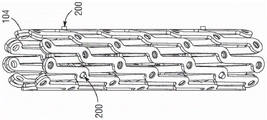
Fig. 3-4 illustrate another embodiment of a prosthetic valve 100 that includes a frame 104 and an expansion and locking mechanism 200 (also referred to as an "actuator"). It should be understood that prosthetic valve 100 can include leaflets 20 and other soft components, such as one or more skirts 70, with skirt 70 removed for illustrative purposes. The expansion and locking mechanism 200 can be used to radially expand and lock the prosthetic valve in a radially expanded state. In the example of fig. 3 and 4, three expansion and locking mechanisms 200 are attached to the frame 104, but in other example delivery assemblies, any number of expansion and locking mechanisms 200 may be used. Fig. 3 shows the expansion and locking mechanism 200 attached to the frame 104 when the frame is in a radially collapsed configuration, while fig. 4 shows the expansion and locking mechanism attached to the frame when the frame is in a radially expanded configuration.
It should be understood that in certain embodiments, prosthetic valve 100 may use other mechanisms for expansion and locking, such as linear actuators, alternative (alternative) locking mechanisms, and alternative expansion and locking mechanisms. Further details regarding the use of linear actuators, locking mechanisms, and expansion and locking mechanisms in prosthetic valves can be found, for example, in U.S. patent No. 10,603,165, which is incorporated herein by reference in its entirety.
Referring to fig. 5A-5C, the expansion and locking mechanism 200 in an exemplary embodiment may include an actuator screw 202 (which in an exemplary embodiment functions as a linear actuator or push-pull member), the actuator screw 202 including a relatively long upper or distal portion 204 and a relatively short lower or proximal portion 206 at the proximal end of the screw 200, wherein the lower portion has a smaller diameter than the upper portion. Both the upper portion 204 and the lower portion 206 of the screw 202 may have an external threaded surface.
The actuator screw 200 may have a distal attachment 208 attached to its distal end, the distal attachment 208 having a radially extending distal valve connector 210. The distal attachment 208 may be secured to the actuator screw 202 (e.g., welded together or manufactured as one piece). The distal valve connector 210 can extend through an opening at or near the distal end of the frame 104 formed at a location on the frame where two or more struts intersect, as shown in fig. 5C. The distal valve connector 210 can be secured to the frame 104 (e.g., welded). Due to the shape of the struts, the distal end of the frame 104 includes an alternating series of distal junctions 150 and distal apices 152. In the illustrated example, the distal valve connectors 210 of the three expansion and locking mechanisms 200 are connected to the frame 104 by distal junctions 250. In other examples, one or more distal valve connectors 210 can be connected to the frame 104 through the distal apex 152. In other embodiments, the distal valve connector 210 can be connected to the joint closer to the proximal end of the frame 104.
The expansion and locking mechanism 200 may further include a sleeve 212. The sleeve 212 may be annularly positioned around the distal portion 204 of the screw 202 and may include axial openings at its proximal and distal ends through which the screw 202 may extend. The axial opening and cavity in the sleeve 212 may have a diameter larger than the diameter of the distal portion 204 of the screw 202 such that the screw may move freely within the sleeve (the screw 202 may move proximally and distally relative to the sleeve 212). Because the actuator screw 202 is free to move within the sleeve, it may be used to radially expand and/or contract the frame 104, as disclosed in further detail below.
The sleeve 212 may have a proximal valve connector 214 extending radially from its outer surface. The proximal valve connector 214 may be secured to the sleeve 212 (e.g., welded). The proximal valve connector 214 can be axially spaced from the distal valve connector 210 such that the proximal valve connector can extend through an opening at or near the proximal end of the frame 104. The proximal end of the frame 104 includes an alternating series of proximal junctions 160 and proximal apices 162. In the illustrated example, the proximal valve connectors 214 of the three expansion and locking mechanisms 200 are connected to the frame 104 by proximal joints 160. In other examples, one or more proximal valve connectors 214 can be connected to the frame 104 through the proximal apex 162. In other embodiments, the proximal valve connector 214 can be connected to the junction closer to the distal end of the frame 104.
It should be understood that the distal connector 210 and the proximal connector 214 need not be connected to opposite ends of the frame. The actuator 200 can be used to expand and compress the frame so long as the distal and proximal connectors are connected to respective engagement portions on the frame that are axially spaced from one another.
The lock nut 216 may be positioned inside the sleeve 212 and may have an internal threaded surface that may engage an external threaded surface of the actuator screw 202. The locking nut 216 may have a notched portion 218 at its proximal end, the purpose of which is described below. The locking nut may be used to lock the frame 104 to a specifically radially expanded state, as discussed below.
Fig. 6 and 7 show an expansion and locking mechanism 200 that includes components of the delivery device that are not shown in fig. 5A-5C. As shown, the expansion and locking mechanism 200 may be releasably coupled to the support tube 220, the actuator member 222, and the locking tool 224. The proximal end of support tube 220 may be connected to a handle or other control device (not shown) used by the physician or operator of the delivery assembly to operate the expansion and locking mechanism 300, as described herein. Similarly, the proximal ends of the actuator member 222 and the locking tool 224 may be connected to a handle.
The support tube 120 annularly surrounds a proximal portion of the locking tool 224 such that the locking tool extends through a lumen of the support tube. The support tube 220 and sleeve are sized such that the distal end of the support tube abuts or engages the proximal end of the sleeve 212 such that the support tube is prevented from moving distally beyond the sleeve.
The actuator member 222 may extend through a lumen of the locking tool 224. The actuator member 222 may be, for example, a shaft, a rod, a cable, or a wire. A distal end portion of the actuator member 222 is releasably connectable to the proximal end portion 206 of the actuator screw 202. For example, the distal end portion of the actuator member 222 may have an internal threaded surface that may engage the external threads of the proximal end portion 206 of the actuator screw 202. Alternatively, the actuator member 222 may have external threads that engage an internally threaded portion of the screw 202. When the actuator member 222 is threaded onto the actuator screw 202, axial movement of the actuator member may cause axial movement of the screw.
A distal portion of the locking tool 224 may annularly surround the actuator screw 202 and extend through the lumen of the sleeve 212, and a proximal portion of the locking tool may annularly surround the actuator member 222 and extend through the lumen of the support tube 220 to the handle of the delivery device. The locking tool 224 may have an internal threaded surface that may engage an external threaded surface of the locking screw 202 such that clockwise or counterclockwise rotation of the locking tool 224 causes the locking tool to advance distally or proximally along the screw, respectively.
The distal end of the locking tool 224 may include a notched portion 226, as may best be seen in fig. 6. The notched portion 226 of the locking tool 224 may have an engagement surface 227, the engagement surface 227 configured to engage a correspondingly shaped engagement surface 219 of the notched portion 218 of the locking nut 216 such that rotation (e.g., clockwise rotation) of the locking tool causes the nut 216 to rotate in the same direction (e.g., clockwise) and advance distally along the locking screw 202. In an exemplary embodiment, the notched portions 218, 226 are configured such that rotation of the locking tool 224 in an opposite direction (e.g., counterclockwise) allows the notched portion 226 of the locking tool 224 to disengage from the notched portion 218 of the locking nut 216; that is, rotation of the locking tool in a direction that causes the locking tool to move proximally does not cause a corresponding rotation of the nut.
In alternative embodiments, the distal end portion of the locking tool 124 may have various other configurations adapted to engage the nut 216 upon rotation of the locking tool 224 and produce rotation of the nut to move the nut distally, such as any of the tool configurations described herein. In some embodiments, the distal end portion of the locking tool 224 may be adapted to produce rotation of the nut 216 in two directions in order to move the nut distally and proximally along the locking screw 202.
In operation, prior to implantation, the actuator member 222 can be threaded onto the proximal end portion 206 of the actuator screw 202 and the lock nut 216 can be rotated such that it is positioned at the proximal end of the screw. The frame 204 can then be placed in a radially collapsed state, and the delivery assembly can be inserted into the patient. After the prosthetic valve is at the desired implantation site, the frame 104 can be radially expanded, as described herein.
To radially expand the frame 104, the support tube 220 may be held firmly against the sleeve 212. The actuator member 222 may then be pulled through the support tube in a proximal direction, such as by pulling on a proximal end of the actuator member or actuating a control knob on the handle that produces proximal movement of the actuator member. Since the support tube 220 is held against the sleeve 212, the sleeve 212 is connected to the proximal end of the frame 104 by the proximal valve connector 214, thus preventing the proximal end of the frame from moving relative to the support tube. Thus, movement of the actuator member 222 in the proximal direction may cause movement of the actuator screw 202 in the proximal direction (as the actuator member is threaded onto the screw), thereby causing the frame 104 to axially shorten and radially expand. Alternatively, the frame 104 may be expanded by moving the support tube 220 distally while holding the actuator member 222 stationary, or moving the support tube distally while moving the actuator member 222 proximally.
After the frame 104 is expanded to a desired radially expanded size, the frame may be locked at the radially expanded size, as described herein. Locking the frame may be achieved by: rotating the locking tool 224 in a clockwise direction causes the notched portion 226 of the locking tool to engage the notched portion 218 of the lock nut 216, thereby advancing the lock nut distally along the actuator screw 202. The locking tool 224 may be rotated so that the locking nut 216 abuts an internal shoulder at the distal end of the sleeve 212 and the locking nut 216 cannot be advanced any further distally (see fig. 6). This will prevent the screw 202 from advancing distally relative to the sleeve 212 and radially compressing the frame 104. However, in the illustrated embodiment, the nut 216 and screw 202 can still be moved proximally through the sleeve 212, allowing for additional expansion of the frame 104 during a valve-in-valve procedure during or after implantation.
After the frame 104 is locked in the radially expanded state, the locking tool 224 may be rotated in a direction that moves the locking tool proximally (e.g., in a counterclockwise direction) to decouple the notched portion 226 from the notched portion 218 of the lock nut 216 and unscrew the locking tool from the actuator screw 202. Additionally, the actuator member 222 may be rotated in a direction to unscrew the actuator member from the lower portion 206 of the actuator screw 202 (e.g., the actuator member 222 may be configured to disengage from the actuator screw when rotated counterclockwise). After the locking means 224 and the actuator member 222 are unscrewed from the actuator screw 202, they may be removed from the patient along with the support tube 220, leaving the actuator screw and the sleeve 212 connected with the frame 104, as shown in fig. 5C, wherein the frame 104 is locked in a particular radially expanded state.
In an alternative embodiment, the locking tool 224 may be formed without internal threads that engage external threads of the actuator screw 202, which may allow the locking tool 224 to slide distally and proximally through the sleeve 212 and along the actuator screw 202 to engage and disengage the nut 216.
In some embodiments, other designs for the expansion and locking mechanism may be used in place of the previously described designs. Details regarding the expansion and locking mechanism can be found, for example, in U.S. patent No. 10,603,165, which is incorporated herein by reference in its entirety.
Fig. 8-9 illustrate another exemplary embodiment of a prosthetic heart valve 300, the prosthetic heart valve 300 including a frame 302 and further including a band 304 configured as a force measuring device. The prosthetic valve 300 can have an outflow end 306 and an inflow end 308, and can include a valve structure (e.g., the valve structure 18) and an inner and/or outer skirt, as previously described, although these components are omitted for purposes of example. The prosthetic valve 300 can also have an actuator and/or locking mechanism as previously described. Although only one side of the frame 302 is depicted in fig. 8-9, it should be understood that the frame 302 forms an annular structure similar to the frame 12 of the prosthetic valve 10 described previously, and that the ribbon 304 has an annular shape extending around the frame 302.
The valve ribbons herein are described with reference to mechanically expandable valves such as those described in U.S. patent No. 10,603,165 and U.S. provisional application No. 63/085,947 filed 9/30/2020, each of which is incorporated herein by reference. For example, some mechanical valves may include pivotable joints between struts, while others may include a unitary (unitary) grid that is expandable and/or compressible via mechanical means. However, it should be understood that the valve ribbons can also be used with other types of transcatheter prosthetic valves, including balloon-expandable prosthetic heart valves, as disclosed in U.S. patent No. 9,393,110 and U.S. publication nos. u.s.2018/0028310 and 2019/0365530, each of which is incorporated herein by reference, and self-expandable prosthetic heart valves, as disclosed in U.S. patent No. 10,098,734, which is incorporated herein by reference.
As described in greater detail below, one or more selected portions of the ribbon 304 can be configured to rupture or break when the prosthetic valve 300 applies a predetermined amount of force (e.g., a radial force) to the ribbon 304. In this manner, the band 304 can be used to determine the real-time diameter of the prosthetic valve, thereby calculating the radial force exerted by the prosthetic valve 300 against the surrounding tissue (e.g., the native valve annulus). When implanting a mechanically expandable prosthetic valve (e.g., prosthetic valve 300), it is desirable to expand the prosthetic valve to the maximum size allowed in view of the patient's anatomy while reducing the risk of annular rupture (e.g., by selecting a size similar to the native valve). To ensure optimal implant dimensions, the diameter of the prosthetic valve and the radial force exerted by the prosthetic valve on the annulus may be monitored in real time during implantation using a measurement device such as a band 304.
The band 304 may include a generally annular or toroidal body 310 extending around the circumference of the frame 302. The body 310 may have a continuous undulating shape including a plurality of peaks 312 alternating with a plurality of valleys 314 around its circumference. The peaks 312 can be positioned such that they are above the valleys 314 along the longitudinal axis a of the prosthetic valve in the orientation shown in fig. 8. In the illustrated embodiment, the peaks 312 are directed toward the outflow end 306 of the prosthetic valve 300, while the valleys 314 are directed toward the inflow end 308 of the prosthetic valve 300.
A plurality of struts 316 may connect adjacent peaks 312 and/or valleys 314. For example, in the illustrated embodiment, from left to right, a first strut 316a extends from each peak 312 to each valley 314 and a second strut 316b extends from valley up to the next peak 312. The struts 316 may be configured in a variety of shapes and sizes, e.g., straight, curved, zig-zag, symmetrical, asymmetrical, etc. For example, in the illustrated embodiment, each strut has a curvilinear shape.
In an alternative embodiment, the ring-shaped body 310 of the band may be formed of strut sections coupled to one another at respective hinges where the strut sections overlap. For example, the strut sections may overlap at each peak 312 and/or valley 314 and may be coupled together via a fastener, such as a rivet or pin, extending through the strut sections. The hinges may allow the strut sections to pivot relative to each other when the band 304 is radially expanded or compressed, such as during expansion and/or compression of the prosthetic valve 300.
As shown in the exemplary embodiment, the body 310 is radially compressible and expandable between a radially compressed state (fig. 9 and 11) and a radially expanded state (fig. 8 and 10). Thus, the band 304 can be crimped or held in a radially compressed state on the radially compressed prosthetic valve in a radially compressed state during delivery, and then expanded to a radially expanded state by expansion of the prosthetic valve at the implantation site.
As shown in fig. 10-11, a circumferential length between adjacent peaks 312 and/or adjacent valleys 314 when the band 304 is in a radially expanded position may be greater than a circumferential length between adjacent peaks 312 and/or adjacent valleys 314 when in a radially compressed state. For example, in FIG. 10, adjacent valleys 314 have a first circumferential length L therebetween1Whereas in fig. 11 adjacent valleys have a second lesser circumferential length L between them2。
In particular embodiments, the ribbon 304 (including the body 310 and the extension member 318 and/or the frangible member 322, described below) may be made of any of the materials described above with respect to the frame 12, including, but not limited to, any of a variety of plastically-expandable materials (e.g., stainless steel or cobalt-chromium alloys) or self-expandable materials (e.g., nitinol).
In some embodiments, the ribbon 304 (including the body 310, and the extension member 318 and/or the frangible member 322) can be made of a bioabsorbable (biorescable) material. In such embodiments, the ribbon 304 can be dissolved and/or absorbed by the body of the patient after the prosthetic valve 300 has been implanted at the selected implantation site within the body of the patient. For example, in some embodiments, the ribbon 304 may include a bioabsorbable polymer configured to dissolve over time. May be used including polymeric materials, additives,Processing, etc., to control the resorption rate of the bioabsorbable ribbon 304. Exemplary bioabsorbable materials include, but are not limited to, Polylactide (PLA), Poly-L-lactide (PLLA), Polyglycolide (PGA), Poly-e-caprolactone (PCL), Trimethylene carbonate (Trimethylene carbonate) (TMC), Poly-DL-lactide (PDLLA), Poly-b-hydroxybutyrate (PBA), Poly-p-dioxanone (PDO), Poly-b-hydroxypropionate (PHPA), and Poly-b-malic acid (PMLA). In other embodiments, body 310 may be formed from a suitable superelastic metal or alloy, such as nitinol. Optionally, spring steel, cobalt chromium alloys such as Or other such resilient metal.
The band 304 may further include a plurality of circumferentially extending extension members 318 extending between adjacent portions of the body 310. For example, in the illustrated embodiment, the extension members 318 extend between one or more adjacent peaks 312. However, in other embodiments, the extension members 318 may extend between adjacent valleys 314. In still other embodiments, some of the extension members 318 may extend between adjacent peaks 312 and other extension members 318 may extend between adjacent valleys 314.
In some embodiments, each pair of adjacent peaks 312 and/or adjacent valleys 314 may include an extension member 318 therebetween. For example, in the illustrated embodiment, each pair of adjacent peaks includes an extension member 318. However, in other embodiments, only a selected pair of adjacent peaks 312 and/or a selected pair of adjacent valleys 314 may include an extension member therebetween.
As shown in fig. 10, the extension members 318 may extend substantially parallel to the circumference of the frame 302 when the band 304 is in a radially expanded state. When the band 304 is in a radially compressed configuration, as shown in fig. 11, the extension member 318 may be axially deformed toward the inflow end 306 and/or the outflow end 308 of the frame 302. In the illustrated embodiment, as shown in fig. 9, the extension member 318 is axially deformed toward the outflow end 308 of the frame 302 to form a substantially U-shaped or V-shaped member having an apex 320.
One or more selected extension members 318 may be configured as frangible members 322. The one or more brittle members 322 may be configured to fracture, break, or otherwise deform when, for example, a force (e.g., a radial force) applied by the frame 302 to the ribbon 304 is greater than a predetermined threshold of force.
As frame 302 moves from the radially compressed configuration (fig. 9) to the radially expanded configuration (fig. 10), the frame axially shortens and radially expands. The band 304 expands radially with the frame from the compressed diameter until it reaches the first predetermined diameter. As prosthetic valve 300 continues to expand (e.g., using actuator 50), frame 302 exerts an increasingly greater radial force on ribbon 304. When the force exceeds a first predetermined threshold, the first frangible member 322 is capable of breaking, thereby allowing the band 304 to radially expand to a second predetermined diameter.
When the band 304 is at a particular diameter, the radial force exerted by the prosthetic valve on the native annulus may be determined based at least in part on a known mathematical relationship between the diameter of the prosthetic valve 300 and the radial force exerted by the prosthetic valve. During the implantation procedure, the physician may monitor the diameter of the valve to determine when the prosthetic valve is at a diameter that best fits the native valve annulus and when an optimal amount of radial force is being applied by the prosthetic valve to the native valve annulus.
As the actuator (e.g., actuator 50) continues to expand the prosthetic valve 300, the prosthetic valve 300 continues to apply a force to the band 304, which band 304 is now expanded to the second predetermined diameter. When the force exceeds a second predetermined threshold (which may be greater than or equal to the first predetermined threshold), the second frangible member 322 is capable of breaking, thereby allowing the body 310 to radially expand to a third predetermined diameter. Each time the frangible member 322 breaks, the diameter of the ribbon 304 (and thus the diameter to which the frame 302 can expand) increases. The process of expanding and fracturing may continue until the prosthetic valve has reached a selected size.
The ribbon 304 may include any number of frangible members 322. For example, in some embodiments, all of the extension members 318 are frangible members 322. In other embodiments, only selected extension members 318 are frangible members 322.
In some embodiments, each frangible member 322 can be configured to break when a predetermined threshold of the same force is exceeded. In other embodiments, each frangible member 322 can be configured to break when a different predetermined threshold of force is exceeded. In still other embodiments, the first set of brittle members 322 may be configured to fracture when a first predetermined threshold of force is exceeded, and the second set of brittle members 322 may be configured to fracture when a second predetermined threshold of force is exceeded. The first predetermined threshold value of force may be greater than the second predetermined threshold value of force and vice versa.
In an exemplary embodiment, the brittle member 322 is a filament strand that includes a material that is weaker than the material forming the body 310. In other embodiments, the frangible member can be, for example, a cable, a shaft, and/or a suture. The filament strand may be configured to break upon application of a force greater than a predetermined threshold of force. In other embodiments, the brittle member 322 may include, for example, a fracture and/or perforated region configured to make the brittle member 322 relatively weaker than the body 310. In still other embodiments, as shown in fig. 12, the brittle member 322 may include a pillar portion 324 and a thinner portion 326 configured to fracture at a force exceeding a predetermined threshold. The post portion 324 may have a first width W1And the thinner portion 326 may have a second width W that is thinner than the first width2。
In still other embodiments, the frangible member 322 can be configured to deform (e.g., by stretching) in the circumferential direction and permanently remain in the deformed configuration when the applied force is greater than a predetermined threshold of force. For example, the frangible member 322 can be configured as a spring and/or other biasing member such as a deformable polymeric member.
In some embodiments, the frangible members 322 can include a radiopaque portion. For example, the radiopaque portion may be arranged such that when the frangible member 322 breaks, the radiopaque portion separates into two radiopaque portions, allowing the physician to determine that the frangible member 322 has broken. For example, when the prosthetic valve is radially expanded, the physician may visualize the band 304 using fluoroscopy. When the force applied to the ribbon 304 exceeds a first predetermined threshold of force, the first frangible member 322 including the radiopaque portion can fracture, thereby separating the radiopaque portion into two pieces. The physician can see the break in the visualization and thus can determine the amount of radial force the prosthetic valve exerts on the native annulus and the diameter of the prosthetic valve. In other embodiments, the radiopaque portion may include a pattern configured to allow a physician to determine when the frangible member 322 has fractured.
In some embodiments, each extension member 318 can include a radiopaque portion. In other embodiments, only the frangible member 322 may include a radiopaque portion. The radiopaque portion may include, for example, gold, platinum, radiopaque nitinol, and/or combinations thereof.
In some embodiments, the ribbon 304 may include a covering configured to prevent the frangible members 322 from scratching and/or damaging the native valve annulus after fracture. In some embodiments, an outer skirt (e.g., outer skirt 70) of the prosthetic valve can be configured as a covering. For example, the band 304 may be disposed between the frame 302 and the outer skirt.
In some or all of the disclosed embodiments, the prosthetic valve 300 can include, in addition to the band 304, one or more additional bands positioned at different locations along the longitudinal axis a of the prosthetic valve 300. The ribbon 304 may have, for example, different predetermined diameters and/or different predetermined thresholds of breakage of the frangible members 322. In some embodiments, the prosthetic valve 300 can include a first band 304 at an inflow end 306 of the frame and a second band 304 at an outflow end 308 of the frame. In other embodiments, the prosthetic valve 300 can include two ribbons 304 positioned adjacent the inflow end 306 and/or the outflow end 308.
In a particular method for implanting a prosthetic heart valve 300 including one or more ribbons 304 in a patient's heart, a physician may use conventional techniques and/or devices to measure the approximate size of the native heart valve to facilitate selection of a desired size of the prosthetic heart valve 300. The prosthetic heart valve 300 can be mounted to a distal portion of a delivery device. The distal portion of the delivery device (along with the prosthetic valve 300) can be advanced through the patient's vasculature toward the native aortic valve. After the prosthetic heart valve 300 is positioned in the desired implantation location (typically within the native aortic annulus), the prosthetic heart valve can be deployed (e.g., radially expanded).
To deploy the prosthetic valve, the physician can actuate a delivery device, which can actuate one or more actuators (e.g., actuators 50 described above) coupled to the prosthetic valve 300. Each actuator may, for example, reduce the distance between the attachment locations of the respective sleeve and nut, thereby causing frame 302 to axially shorten and radially expand. The prosthetic valve 300 (including the band 304) can continue to radially expand until it reaches a first predetermined diameter at which the band 304 can no longer expand. The physician can then assess the fit of the prosthetic valve within the native valve annulus and utilize the first predetermined diameter to determine the force exerted by the prosthetic valve 300 against the native valve annulus.
In some embodiments, the ribbon 304 can provide tactile feedback to the physician during the implantation procedure. For example, the physician can feel (e.g., via the handle of the delivery device) when the frangible member 322 breaks.
If further expansion of the prosthetic valve is desired, the prosthetic valve 300 can be expanded by continuing to actuate the actuator such that the prosthetic valve expands and applies a force to the band 304 until a predetermined threshold of force is exceeded, causing the first frangible members 322 to break and allowing the band 304, and thus the prosthetic valve 300, to expand to the second predetermined diameter. The physician can then re-evaluate the fit of the prosthetic valve within the native valve annulus and recalculate the forces applied to the native valve annulus. This process can be repeated as necessary until the prosthetic valve 300 is expanded to a diameter that best fits the native annulus. For example, the prosthetic valve 300 desirably is expanded to a diameter sufficient to anchor the prosthetic valve in place against surrounding tissue with minimal or no paravalvular leakage and without over-expanding and fracturing the native annulus.
Referring now to fig. 13, in an alternative embodiment, the prosthetic valve 300 can include a band 400. The ribbon 400 can be used in place of the ribbon 304, or the ribbon 400 can be used in addition to the ribbon 304, and can be disposed around the circumference of the prosthetic valve 300.
The ribbon 400 can include an elongated member 402 having a first end 404 and a second end 406, the second end 406 including a retaining member 408. The ribbon 400 can include a plurality of stops 410 spaced apart from one another along at least a portion of the elongated member 402. The elongated member 402 may be, for example, a cable, a wire, and/or a suture. In the illustrated embodiment, the stop 410 is configured as a plurality of spheres disposed on the elongated member 402. In other embodiments, the stop 410 may have any of a variety of shapes.
The elongate member 402 can be looped such that the first end 404 extends through the retaining member 408, thereby forming an annular shape around the circumference of the prosthetic valve 300. In some embodiments, the elongate member 402 can include a stopper-less portion (stopper-less portion) along which the retaining member 408 can slide during expansion of the prosthetic valve. The position of the stop 410 and the length of the no stop portion can be selected to provide a first diameter of the frame 302 of the prosthetic valve.
In some embodiments, as exemplified, the stop 410 may be secured to the elongated member 402 at spaced apart locations using a second elongated member configured as a securing member 412. In other embodiments, the stop 410 may be integrally formed with the elongated member 402.
As shown in fig. 13, the retaining member 408 may comprise a ring or loop formed along the end 406. The collar may be sized so that its opening is equal to or slightly smaller than the diameter of the stop 410. Thus, sufficient force must be applied to force the stop 410 through the retaining member 408, as described in more detail below. In other embodiments, the retaining member 408 may have any of a variety of shapes corresponding to the shape of the stopper 410 and configured to allow the stopper 410 to pass through the retaining member 408 when sufficient force is applied.
As the prosthetic valve 300 is expanded (thereby increasing the circumference of the elongate member 402), the retaining member 408 can slide along the non-stop portion 416 of the elongate member 402 until it reaches a first stop (e.g., stop 410a in the illustrated embodiment). The first stop 410a prevents the retaining member 408 from continuing to slide along the elongate member 402, thereby maintaining the ribbon 400 (and thus the prosthetic valve 300) at the first predetermined diameter. The first radial force exerted by the prosthetic valve 300 on the native annulus can be determined based at least in part on a known mathematical relationship between the diameter of the prosthetic valve and the radial force exerted by the prosthetic valve.
As prosthetic valve 300 continues to expand (e.g., using actuator 50), frame 302 exerts an increasingly greater force on band 400. When the force exceeds a first predetermined threshold, the first stop 410a may pass through the retaining member 408, allowing the retaining member to slide along the first elongated member 402 until it reaches the second stop 410b, the second stop 410b maintaining the ribbon 400 at a second predetermined diameter. The second force exerted by the prosthetic valve 300 on the native valve annulus can be determined as previously described.
As the actuator (e.g., actuator 50 described above) continues to expand the prosthetic valve 300, the prosthetic valve 300 will continue to exert more and more force on the band 400. When the force exceeds a second predetermined threshold (which may be greater than or equal to the first predetermined threshold), the second stop 410b may pass through the retaining member 408, allowing the retaining member 408 to slide along the elongated member until it reaches a third stop 410c, which third stop 410c maintains the ribbon 400 at a third predetermined diameter. The diameter of the ribbon 400 (and thus the diameter to which the frame 302 can expand) increases each time the stop 410 passes through the retaining member 408. The expansion process may continue until the prosthetic valve reaches a selected size. Throughout the implantation procedure, the physician can continuously monitor the diameter of the valve to determine when the prosthetic valve is at a diameter that best fits the native valve annulus and when the optimal amount of radial force is being applied by the prosthetic valve to the native valve annulus. In some embodiments, the ribbon 400 can provide tactile feedback to the physician during the implantation procedure. For example, the practitioner can feel (e.g., via the handle of the delivery device) when the retaining member 408 contacts the stop 410 and/or when the retaining member 408 moves past the stop 410.
In some embodiments, the stop 410 positioned at the end of the first end 404 may be configured as an enlarged stop 414. Enlarged stop 414 may have a diameter larger than other stops 410 and larger than the opening of retaining member 408 such that enlarged stop 414 is prevented from passing through retaining member 408. The enlarged stop 414 can have a diameter large enough such that the amount of force applied by the prosthetic valve 300 is insufficient to cause the enlarged stop to pass through the retention member 408. In this manner, the enlarged stop 414 can create a maximum diameter beyond which the prosthetic valve 300 is prevented from expanding.
In some embodiments, one or more of the stop 410 and/or the retaining member 408 can include a radiopaque portion. As the prosthetic valve is radially expanded, the physician may visualize the ribbon 400 using fluoroscopy and may determine the diameter of the prosthetic valve 300 based on the position of the stop 410 relative to the retaining member 408. For example, in certain instances, the physician may determine that two stops 410 have passed through the retention member 408, and thereby determine that the prosthetic valve is expanded to the third predetermined diameter. The physician can then determine the radial force exerted by the prosthetic valve based at least in part on the known mathematical relationship between the diameter of the prosthetic valve and the radial force exerted by the prosthetic valve.
In another alternative embodiment, the belt may include a ratchet mechanism. For example, an exemplary embodiment of a band can include an elongate member extending around a circumference of a prosthetic valve and having a first end and a second end. The second end may include a ratchet mechanism. In some embodiments, the first end portion may include a plurality of teeth or other features configured to interact with the ratchet mechanism.
The elongate member may be looped such that the first end extends through the ratchet mechanism, forming an annular shape around a circumference of the prosthetic valve. As the prosthetic valve expands, the first end portion may move relative to the ratchet portion until a first predetermined diameter is reached, at which point the ratchet mechanism may engage the first end portion and prevent further expansion of the prosthetic valve. The ratchet mechanism may be configured to maintain the valve at a first predetermined diameter until a force greater than a first predetermined threshold is applied to the band. The ratchet member may allow the first end to move relative to the ratchet member when the force applied by the prosthetic valve exceeds a first predetermined threshold until a second predetermined diameter is reached. The expansion process may continue until the prosthetic valve reaches a selected size.
Referring now to fig. 14, in an alternative embodiment, the prosthetic valve 300 can include a band 500. The ribbon 500 can be used in place of the ribbons 304 and 400, or the ribbon 500 can be used in addition to the ribbons 304 and 400, and can be disposed around the circumference of the prosthetic valve 300. Ribbon 500 may be similar to ribbon 304 except that the body 501 of ribbon 500 includes a plurality of loops 502 instead of a plurality of alternating peaks and valleys.
The ribbon 500 may include an annular body portion 501, the annular body portion 501 including a plurality of loops or rings 502. As shown in the illustrated embodiment, each ring 502 may have a substantially elliptical shape including a first end 504, a second end 506, and a first central portion 508 and a second central portion 510 each extending between the first end and the second end. In other embodiments, the ring 502 may have any of a variety of shapes, including but not limited to circular, square, rectangular, triangular, diamond, square-oval (square-ovals), and the like. The ribbon 500 may be made of any of the materials discussed above with respect to the ribbon 304.
Each ring 502 may be coupled to one or more adjacent rings at the first central portion 508 and/or the second central portion 510. In other embodiments, each loop 502 may be coupled to one or more adjacent loops at first end 504 and/or second end 506.
The band 500 is radially compressible and expandable between a radially compressed state and a radially expanded state (fig. 14). The circumferential length between the first and second central portions 508, 510 of the respective ring 502 when the band 500 is in the radially expanded position may be greater than the circumferential length between the first and second central portions 508, 510 of the respective ring when in the radially compressed position.
The band 500 may include a plurality of circumferentially extending extension members 512 extending between adjacent portions of the body 501. For example, in the illustrated embodiment, the extension members 512 extend between the first and second central portions 508, 510 of each ring 502. However, in other embodiments, the extension members 512 may extend between the first ends 504 of adjacent loops, between the second ends 506 of adjacent loops, and/or any combination of the foregoing.
One or more selected extending members 512 may be configured as a frangible member 514, similar to the frangible members 322 described above. The one or more frangible members 514 can be configured to break, fracture, or otherwise deform (such as by stretching) when, for example, a force (e.g., a radial force) applied by the prosthetic valve 300 to the band 500 is greater than a predetermined threshold of force).
As the prosthetic valve 300 expands, the band 500 expands radially with the frame from the compressed diameter until it reaches the first predetermined diameter. As prosthetic valve 300 continues to expand, frame 302 exerts an increasing radial force on band 500. When the force exceeds a first predetermined threshold, the first frangible member 514 is capable of breaking, thereby allowing the ribbon 500 to radially expand to a second predetermined diameter. The first radial force exerted by the prosthetic valve 300 on the native annulus can be determined based at least in part on a known mathematical relationship between the diameter of the prosthetic valve and the radial force exerted by the prosthetic valve.
As prosthetic valve 300 continues to expand, frame 302 exerts an increasing force on band 500, and band 500 is now expanded to the second predetermined diameter. When the force exceeds a second predetermined threshold (which may be greater than or equal to the first predetermined threshold), the second frangible member 514 is capable of breaking, thereby allowing the body 501 to radially expand to a third predetermined diameter. Each time the frangible member 514 fractures, the diameter of the ribbon 500 (and thus the diameter to which the frame 302 can expand) increases. The process of expanding and fracturing can continue until the prosthetic valve reaches a selected size.
Fig. 15 illustrates a delivery device 600 according to one embodiment, which is adapted to deliver a prosthetic heart valve 602, such as any of the prosthetic heart valves described herein. The prosthetic valve 602 can be releasably coupled to the delivery apparatus 600. It should be understood that the delivery apparatus 600 and other delivery apparatuses disclosed herein can be used to implant prosthetic devices other than prosthetic valves, such as stents or grafts.
The delivery apparatus 600 in the illustrated embodiment generally includes a handle 604 and a first elongate shaft 606 (which in the illustrated embodiment includes an outer shaft) extending distally from the handle 604.
In embodiments where the prosthetic valve 602 is a mechanically expandable prosthetic valve, such as the embodiment illustrated in fig. 15, the delivery apparatus 600 can include at least one actuator assembly 608 extending distally through the outer shaft 606. The at least one actuator assembly 608 can be configured to radially expand and/or radially collapse the prosthetic valve 602 when actuated. Although the illustrated embodiment shows two actuator assemblies 608 for purposes of example, it should be understood that one actuator 608 may be provided for each actuator on a corresponding prosthetic valve. For example, three actuator assemblies 608 can be provided for a prosthetic valve having three actuators. In other embodiments, there may be a greater or lesser number of actuator assemblies.
The actuator assembly 608 can be releasably coupled to the prosthetic valve 602. For example, in the illustrated embodiment, each actuator assembly 608 can be coupled to a respective actuator of the prosthetic valve 602. Each actuator assembly 608 may include, for example, a support tube, an actuator member, and a locking tool. When actuated, the actuator assembly can transmit a pushing and/or pulling force to a portion of the prosthetic valve to radially expand and collapse the prosthetic valve. The actuator assembly 608 may be at least partially radially disposed within and axially extend through one or more cavities of the outer shaft 606. For example, the actuator assembly 608 may extend through a central lumen of the shaft 606 or through separate corresponding lumens formed in the shaft 606.
In embodiments where the prosthetic valve 602 is a self-expanding prosthetic valve or a balloon-expandable prosthetic valve, the delivery device 600 need not include the actuator 608.
In some embodiments, the distal portion 616 of the shaft 606 can be sized to accommodate the prosthetic valve in its radially compressed delivery state during delivery of the prosthetic valve through the patient's vasculature. In this manner, the distal portion 616 functions as a delivery sheath or capsule (capsule) for the prosthetic valve during delivery.
The handle 602 of the delivery device 600 can include one or more control mechanisms (e.g., knobs or other actuation mechanisms) for controlling the various components of the delivery device 600 in order to expand and/or deploy the prosthetic valve 602. For example, in the illustrated embodiment, the handle 602 includes a first knob 610, a second knob 612, and a third knob 614.
The first knob 610 can be a rotatable knob configured to produce axial movement of the outer shaft 606 in a distal and/or proximal direction relative to the prosthetic valve 602 to deploy the prosthetic valve from the delivery sheath 616 once the prosthetic valve has been advanced to a position at or adjacent to a desired implantation location within a patient's body. For example, rotation of the first knob 610 in a first direction (e.g., clockwise) can proximally retract the sheath 616 relative to the prosthetic valve 602, while rotation of the first knob 610 in a second direction (e.g., counterclockwise) can distally advance the sheath 616. In other embodiments, the first knob 610 may be actuated by axially sliding or moving the knob 610, such as pulling and/or pushing the knob. In other embodiments, actuation of the first knob 610 (rotational or sliding movement of the knob 610) can produce axial movement of the actuator assembly 608 (and thus the prosthetic valve 602) relative to the delivery sheath 616 to advance the prosthetic valve distally from the sheath 616.
In some embodiments, the second knob 612 can be a rotatable knob configured to produce radial expansion and/or contraction of the prosthetic valve 602. Rotation of the second knob 612 in a first direction (e.g., clockwise) can radially expand the prosthetic valve 602, while rotation of the second knob 612 in a second direction (e.g., counterclockwise) can radially collapse the prosthetic valve 602. In other embodiments, the second knob 612 may be actuated by axially sliding or moving the knob 612, such as pulling and/or pushing the knob.
In some embodiments, the third knob 614 can be a rotatable knob configured to hold the prosthetic heart valve 602 in its expanded configuration. Rotation of the third knob in a first direction (e.g., clockwise) can, for example, rotate each locking tool to advance the locking nuts to their distal positions to resist radial compression of the frame of the prosthetic valve. Rotation of the knob 614 in an opposite direction (e.g., counterclockwise) may rotate each locking tool in an opposite direction to decouple each locking tool from the respective nut and remove the locking tool from the respective actuator screw. In other embodiments, the third knob 614 may be actuated by axially sliding or moving the third knob 614, such as pulling and/or pushing the knob.
Although not shown, the handle 604 may include a fourth rotatable knob operatively connected to a proximal end portion of each actuator member. The fourth knob may be configured to rotate each actuator member upon rotation of the knob to unscrew each actuator member from the proximal portion of the respective actuator. After the locking means and the actuator member are unscrewed from the actuator screw, they can be removed from the patient together with the support tube.
In some embodiments, the prosthetic valve 700 with the frame 702 can include one or more restraining members/ribbons/bands 704 configured to prevent the prosthetic valve 700 from expanding beyond a selected diameter in place of, or in addition to, valve ribbons such as the valve ribbons 304, 400, or 500. Although the example prosthetic valve 700 is a self-expanding prosthetic valve, it should be understood that such a restraining band 704 may be used with any type of prosthetic valve, including mechanical valves such as disclosed in U.S. provisional application No. 63/085,947 and U.S. patent No. 10,603,165, filed 9, 30, 2020, balloon-expandable prosthetic heart valves such as disclosed in U.S. patent publication nos. u.2018/0028310 and u.s.2012/0123529, and self-expandable prosthetic heart valves such as disclosed in U.S. publication No. 2015/0157455.
The prosthetic valve 700 includes a frame 702 having an inflow end 706 and an outflow end 708, and may include a valve structure 703 (fig. 17) (similar to valve structure 18) and an inner skirt 718 (fig. 17). In some embodiments, the prosthetic valve 700 can further include one or more outer skirts, as previously described, these components being omitted for purposes of illustration. The frame 702 may include a plurality of struts 710 coupled together in an open lattice pattern defining a plurality of cells 712.
As shown in fig. 16, the constraining band 704 may extend around the circumference of the frame 702. The constraining band 704 may be configured to expand to a maximum diameter DMSuch that the band allows the frame 702 to expand to a maximum diameter DMAnd prevents further expansion of the frame 702 beyond the maximum diameter DM. In some embodiments, the restraining strip 704 may comprise, for example, an elastic cloth. The restraining strip 704 may have a length L extending axially along a longitudinal axis a of the frame 702l. In other embodiments, the band 704 may have a greater or lesser width. For example, in some embodiments, the restraining band 704 can extend substantially along the entire length of the prosthetic valve 700, thereby uniformly restraining the prosthetic valve from maximum expansion along its length.
In some embodiments, the constraining band 704 may comprise fibers woven such that they extend at a non-parallel and non-perpendicular angle relative to the inflow edge 714 and/or outflow edge 716 of the band 704. For example, the fibers may be woven such that they are oriented at a 45 degree angle with respect to the outflow edge 714 and inflow edge 716. This configuration allows the restraining strip 704 to elongate in the axial and/or circumferential directions as the frame 702 moves.
As described above, the prosthetic valve 700 can be a self-expanding prosthetic valve. In some embodiments, a prosthetic valve700 may be deployed during implantation to less than the maximum diameter D of the constraining band 704MSuch that the band 704 does not constrain expansion and/or does not fully tension around the prosthetic valve 700, for example. For example, the maximum diameter DMMay be larger than the diameter of the native annulus. In such embodiments, if the native valve annulus loses tension over time, thereby allowing the prosthetic valve 700 to further self-expand, the restraining band 704 can function to prevent the prosthetic valve 700 from expanding beyond the restraining band's maximum diameter DMThe function of (1). This configuration will prevent dilation beyond the maximum selected diameter D even though the forces exerted by the native annulus are reducedMWhile advantageously mitigating the risk of late coronary occlusion (DCO). At maximum diameter DMThe force exerted by the restraining band 704 may be greater than the radial expansion force of the self-expandable valve.
In some embodiments, a physician may be provided with a plurality of prosthetic valves, each prosthetic valve including a valve having a different selected maximum diameter DMThe restraining strip 704. Thus, the physician can select the maximum diameter DMA suitable prosthetic valve/constraining band combination that best fits the particular anatomy of the patient. In other embodiments, the physician can select a particular restraining strip 704 to attach to the pre-assembled prosthetic valve.
Although in the illustrated embodiment, the restraining strip 704 is positioned centrally along the longitudinal axis a of the frame 702, in other embodiments, the restraining strip 304 may be positioned closer to or further from the outflow end 706 and/or the inflow end 708. For example, in some embodiments, the prosthetic valve 700 can include a restraining band 704 positioned at an outflow end 708 (e.g., defining an a-shape) of the frame 702. Such a configuration may advantageously restrict the outflow end 708 from expanding and potentially occluding the native coronary artery, while still allowing the inflow end 706 of the prosthetic valve to expand unrestrained to a larger diameter within the native annulus, preventing or reducing prosthetic valve migration if the tension of the native annulus decreases over time. In another example, the prosthetic valve 700 can include a restraining band 704 positioned at an inflow end 706 of the frame 702 (e.g., defining a V-shape). Such a configuration may advantageously limit over-expansion of the inflow end 706, thereby preventing or mitigating the risk of anatomical rupture. In still other examples, the prosthetic valve 700 can include constraining bands at the outflow end 708 and the inflow end 706, defining a cylindrical frame. Such a configuration can advantageously prevent the outflow end 708 from occluding the coronary ostia while also preventing the prosthetic valve 700 from over-expanding against the native annulus to mitigate the risk of tissue damage or conduction disturbances.
Although only one restraining band 704 is shown in the illustrated embodiment, in other embodiments, the prosthetic valve 700 can include multiple restraining bands 704. The plurality of constraining bands 704 can be disposed in any of a variety of configurations along the longitudinal axis a of the prosthetic valve 700. In some embodiments, the restraining strips 704 may be spaced apart from each other along the longitudinal axis a of the frame 702. In other embodiments, the constraining bands 704 may be arranged such that they completely or partially overlap with one or more adjacent bands 704.
In some embodiments, the restraining band 704 can be coupled to the prosthetic valve 700 during assembly of the prosthetic valve. For example, in some embodiments, as shown in fig. 17, the restraining band 704 can be coupled to the prosthetic valve 700 by suturing the restraining band 704 to the inner skirt 718 using one or more sutures 720. However, in other embodiments, the restraining band 704 may be stitched directly to the frame 702 (e.g., along the posts 710 of the frame, and/or at the joints 722 of the frame), for example, using a suture loop extending around the posts 710 and/or joints 722 of the frame.
Referring to fig. 18, in some embodiments, the restraining strip 704 may be configured as a ribbon 724 comprising wires, cords, and/or cables. The band 724 may extend circumferentially around the frame 702. In some embodiments, as shown in fig. 18, the ribbon 724 may be coupled to the frame 702 by weaving the ribbon 724 through the cells 712 of the frame, for example, in an in-out pattern. In other embodiments, the ribbon 724 may be coupled to the frame 702 via a plurality of sutures. In still other embodiments, the frame 702 may include a plurality of eyelets or holes through which portions of the ribbon 724 may be threaded.
In some embodiments, ribbon 724 may comprise multiple strands of material. For example, in the illustrated embodiment, the ribbon 724 includes a first strand 726 and a second strand 728. The first strands 726 may be braided in an in-out pattern through the cells 712 of the frame 702 such that portions of the first strands 726 are disposed on a radially outer surface 730 of the frame 702 and other portions 726 of the first strands are disposed on a radially inner surface 732 of the frame 702. Second strands 728 may also be braided in an in-out pattern through cells 712 of the frame. In some embodiments, the second strand 728 may be braided such that it is at least partially opposite the first strand 726. For example, at selected circumferential points on the frame 702, the first strands 726 may be disposed on the radially outer surface 730 and the second strands 728 may be disposed on the radially inner surface 732.
Referring now to fig. 19, in some embodiments, a prosthetic valve 700 can include a plurality of constraining ribbons or bands 734, each constraining ribbon or band 734 including a different maximum diameter DMConfigured so that the physician can select a suitable maximum diameter D for the patientM。
As shown in fig. 19, in some embodiments, the prosthetic valve 700 can include three restraining bands 734a, 734b, 734 c. The first constraining band 734a may have a first maximum diameter DM1The second constraining band 734b may have a diameter greater than the first maximum diameter DM1Second maximum diameter DM2And the third constraining band 734c may have a diameter greater than the first maximum diameter DM1And a second maximum diameter DM2Third maximum diameter D of bothM3. In other embodiments, the prosthetic valve 700 can include a greater or lesser number of restraining bands 734.
In some embodiments, one or more of the restraining strips 734 may be configured as a ribbon comprising wires, cords, and/or cables, and/or may comprise an elastic cloth similar to the restraining strip 704. In some embodiments, each restraining strip 734 may comprise the same material. However, in other embodiments, one or more of the constraining bands 734 may comprise a different material.
In use, a physician may analyze a particular anatomy of a patient (e.g., using angiograms and/or CT scans) prior to an implantation procedure, and may select an appropriate maximum diameter DMFor the inflow end and/or the outflow end of the frame. The physician may then cut, sever, or otherwise remove any maximum diameter DMA constraining band 734 that is less than the selected maximum diameter. Thus, after the prosthetic valve is delivered to the implantation site using a delivery device such as delivery device 600 and distal portion 616 has been retracted, the inflow and/or outflow ends of prosthetic valve 700 can self-expand to a diameter no greater than the selected maximum diameter.
In some embodiments, the prosthetic valve 700 can include a plurality of constraining bands 734 at the outflow end 708 and a plurality of constraining bands 734 at the inflow end 706. By cutting any constraining band 734 having a maximum diameter that is less than the selected maximum diameter, the physician can select a maximum diameter for each of the inflow end 706 and outflow end 708 of the prosthetic valve (e.g., a particular anatomy of the patient as determined based on angiograms and/or CT scans). Such a configuration can advantageously prevent the outflow end 708 of the prosthetic valve 700 from occluding the coronary ostia, while also preventing the prosthetic valve 700 from over-expanding against the native annulus to mitigate the risk of tissue damage or conduction disturbance. In some embodiments, the physician may select a restriction band having the same maximum diameter for each inflow and outflow end (e.g., to define a cylindrical or cylindrical shape for the frame), however, in other embodiments, the physician may select a restriction band having a different maximum diameter for each inflow and outflow end (e.g., to define an a-shape or V-shape for the frame).
In other embodiments, the restraining strip 734 may be a single strip having discrete release levels (e.g., similar to the previously described ribbons 304, 400, and 500). One or more of such restraining straps 734 may be disposed about the frame 702. For example, a first band may be positioned at the inflow end and a second band may be positioned at the outflow end. In such embodiments, the physician can analyze the particular anatomy of the patient to determine the selected inflow end diameter and the selected outflow end diameter of the prosthetic valve as previously described. It has thus been determined that the physician can partially release the first and second constraining bands (e.g., by severing or breaking portions of the bands, and/or by using a ratcheting mechanism) such that each band can expand to a selected maximum diameter. In some embodiments, the physician may release the constraining bands such that the same maximum diameter is selected for each inflow and outflow end (e.g., to define a cylindrical or cylindrical shape for the frame), however, in other embodiments, the physician may release the constraining bands such that they have different maximum diameters for each inflow and outflow end (e.g., to define an a-shape or V-shape for the frame).
The constraint band embodiments described herein advantageously increase the usability of prosthetic valves by providing a wide range of potential maximum diameters to which prosthetic valves can be expanded without requiring a physician to stock and maintain a wide variety of prosthetic valves. When using mechanically expandable valves, the physician cannot always determine the diameter of the prosthetic valve in real time during the expansion process. The use of one or more restraining bands, such as bands 704, 724, and/or 734, can prevent inadvertent over-expansion of the mechanically-expandable prosthetic valve beyond a selected maximum diameter. Likewise, when using a balloon-expandable valve, the use of one or more restraining bands can prevent the balloon-expandable prosthetic valve from inadvertently over-expanding beyond a selected maximum diameter.
In some embodiments, as shown in fig. 19, each of the plurality of constraining bands 734 can be coupled to the same portion (e.g., the central portion, the outflow end, and/or the inflow end) of the prosthetic valve 700 and can be axially spaced in close proximity to the other constraining bands. The space between each strap and one or more adjacent straps 734 may be selected to allow for easy cutting/removal of the unselected strap(s) (e.g., using scissors).
In the illustrated embodiment, the restraining band 734 is coupled to the prosthetic valve 700 by weaving the restraining band 734 through the cells 712 of the frame 702 in an in-and-out pattern. To remove any undesired restraining band 734, the physician may cut the band itself (cut through). In other embodiments, each of the plurality of restraining bands 734 can be coupled to a plurality of discrete attachment points of the prosthetic valve 700 using, for example, a suture loop. For example, the restraining band 734 may be coupled to the prosthetic valve 700 using two circumferentially opposing suture loops. In such embodiments, the physician may cut both suture loops to remove the constraining band 734.
Referring now to fig. 20-21, a prosthetic valve 800 having a frame 802 may include flexible tension members 804 configured to allow controllable, progressive valve expansion in place of, or in addition to, valve ribbons such as valve ribbons 304, 400, or 500. The tension members 804 may apply a radially inwardly directed force to the frame 802, which may gradually decrease such that the frame may expand to a selected diameter at a controlled rate (e.g., a rate selected by a physician).
Although the example prosthetic valve 800 is a mechanically expandable prosthetic valve, it should be understood that the tension members 804 described herein may be used with any type of prosthetic valve, including mechanical valves such as disclosed in U.S. provisional application No. 63/085,947 and U.S. patent No. 10,603,165, filed 9, 30, 2020, balloon expandable prosthetic heart valves such as disclosed in U.S. publication nos. u.2018/0028310 and u.s.2012/0123529, and self-expandable prosthetic heart valves such as disclosed in U.S. publication No. 2015/0157455.
The prosthetic valve 800 includes a frame 802 having an inflow end 806 and an outflow end 808, and may include a valve structure (e.g., the valve structure 18) and an inner and/or outer skirt, as previously described, although these components are omitted for purposes of illustration. The frame 802 may include a plurality of struts 810 coupled together at joints 812 in a grid pattern defining a plurality of cells 814. The prosthetic valve 800 can have a self-expandable range (e.g., the frame 802 can inherently self-expand from a fully collapsed diameter to a partially expanded diameter), and a mechanically expandable range (e.g., the frame 802 can mechanically expand from a partially expanded diameter to a fully expanded diameter). The prosthetic valve 800 can include one or more expansion and locking mechanisms 816 (e.g., three) configured to mechanically expand the frame 802 from a partially expanded diameter to a fully expanded diameter and to lock the frame 802 in a radially expanded configuration.
As shown in fig. 20, the flexible tension member 804 may have a first end 818 releasably coupled to the frame 802 at a first location and a second end 820 coupled to a handle of a delivery device (e.g., the handle 604 of the device 600 shown in fig. 15). The handle 604 can include a knob or other actuation mechanism operably coupled to the tension member 804 to apply a force (e.g., a proximally directed force) to the tension member 804. In the illustrated embodiment, the first end 818 is coupled to the frame at a location adjacent to the inflow end 806. However, in other embodiments, first end 818 may be coupled to frame 802 at any axial location along the length of the frame and at any location circumferentially around frame 802.
As shown in fig. 20, in some embodiments, the tension members 804 may be coupled to the frame 802 by weaving the tension members 804 in and out through selected cells 814 of the frame 802. At some points, the tension members 804 may extend on the radially outer surface 822 of the frame, while at other points, the tension members 804 may extend on the radially inner surface 824 of the frame. In some embodiments, portions of the tension members 804 may pass between a radially inner surface 824 of the frame and a radially outer surface 826 of one or more expansion and locking mechanisms 816. In other embodiments, the tension members 804 may be coupled to the frame 802 at selected attachment points by, for example, passing the tension members 804 through one or more holes and/or openings formed in the struts 810 and/or at joints 812 or the like formed between the struts 810.
The tension member 804 may be, for example, a suture (e.g., a monofilament suture or a multifilament suture), a flexible wire (e.g., a metal wire formed of stainless steel, nitinol, or other suitable metal), a cable (e.g., a braided cable formed of metal or polymer strands), or any other similar material that may be threaded through the frame 802 and placed under tension to radially compress the prosthetic valve as described herein.
In the illustrated embodiment, the first end 818 of the tension member 804 is releasably coupled to the frame 802 using one or more knots 828. However, in other embodiments, the tension member 804 may be releasably coupled to the frame using one or more clamps, hooks, and/or other such releasable mechanisms. In some embodiments, an optional sheath or tube may extend over the second end 820 of the tension member 804.
In some embodiments, the tension member 804 may pass through a locking component coupled to the frame 802. The locking member may be configured to maintain the tension member 804 at a selected tension to maintain the frame 802 at a selected diameter. Such a configuration may advantageously prevent or mitigate further spontaneous radial expansion of the prosthetic valve.
The tension members 804 can be used to gradually allow the prosthetic valve 800 to expand in the following exemplary manner. The prosthetic valve 800 can be coupled to a delivery device, such as the delivery device 600 described above. The distal portion of the delivery device 600 (along with the prosthetic valve 800) can be advanced through the patient's vasculature to a selected implantation site.
After being at the implantation site, the distal portion 616 of the shaft 606 covering the prosthetic valve 800 can be retracted, and the tension member 804 can be tensioned (e.g., using the handle 604) to prevent inherent expansion caused by the natural elasticity of the frame 802.
The tension members 804 may continue to be tensioned as one or more expansion forces are applied to the frame (e.g., using the expansion and locking mechanism 816). The tension in the tension members 804 may be gradually released, allowing the frame to gradually (e.g., at a controlled rate) expand to a larger diameter and/or its fully expanded diameter. Such a configuration may advantageously prevent or mitigate inadvertent radial expansion of the prosthetic valve (e.g., caused by inherent frame expansion) and/or control expansion to prevent radial "jumping" caused by, for example, a step-wise expansion mechanism (e.g., an expansion and locking mechanism utilizing a ratchet system), thereby maximizing physician control over positioning the prosthetic valve.
In some embodiments, after the prosthetic valve 800 has been expanded, the tension in the tension members 804 can be fully released and the tension members 804 can be decoupled from the frame 802. The delivery device 600 can be released from the prosthetic valve 800 and removed from the body. In other embodiments, such as embodiments that include a locking component, the tension member 804 can be separate from the delivery device 600 and can remain with the prosthetic valve 800 within the body of the patient.
Additional examples of the disclosed technology
In view of the above-described embodiments of the disclosed subject matter, the present application discloses additional examples that are listed below. It should be noted that one feature of an example alone or in combination, optionally with one or more features of one or more other examples, is more than one feature of an example that also falls within the disclosure of the present application.
Example 1. a ribbon for an implantable prosthetic device, comprising:
an annular body comprising a plurality of alternating peaks and valleys;
a plurality of brittle members extending between at least one of adjacent peaks and adjacent valleys;
wherein upon application of a radially outwardly directed force via the expandable implantable prosthetic device, the annular body is radially expandable from a radially compressed configuration to a first diameter; and is
Wherein a first brittle member of the plurality of brittle members is configured to fracture when the radially outwardly directed force exceeds a first predetermined threshold to allow the annular body to radially expand to a second diameter.
Example 2. any example herein, particularly the ribbon of example 1, wherein a second brittle member of the plurality of brittle members may be configured to fracture when the radially outwardly directed force exceeds a second predetermined threshold to allow the annular body to radially expand to a third diameter.
Example 3. the ribbon of any of the examples herein, particularly examples 1-2, wherein the plurality of brittle members comprises filaments.
Example 4. the ribbon of any of the examples herein, particularly any one of examples 1-3, wherein the brittle member comprises at least one of a crack and a perforated region.
Example 5. an assembly comprising:
an implantable prosthetic device comprising a frame movable between a radially compressed configuration and a radially expanded configuration; and
a band extending circumferentially around the frame, the band configured to radially expand to a first diameter upon application of a first force below a predetermined threshold and to expand to a second diameter upon application of a second force greater than the predetermined threshold.
Example 6. any of the examples herein, particularly the assembly of example 5, wherein the ribbon comprises a plurality of frangible members, and wherein the first frangible member is configured to fracture when the second force is applied to the ribbon, thereby allowing the ribbon to radially expand to the second diameter.
Example 7. the assembly of any of the examples herein, particularly any of examples 5-6, the band further comprising an annular body comprising a plurality of alternating peaks and valleys, the annular body movable between a radially compressed configuration and a radially expanded configuration.
Example 8. the assembly of any example herein, particularly example 7, wherein each brittle member extends between at least one of an adjacent peak and an adjacent valley.
Example 9. any of the examples herein, particularly the assemblies of examples 6-8, wherein the predetermined threshold of force is a first predetermined threshold of force, and wherein the second frangible member is configured to break when a force greater than a second predetermined threshold of force is applied to the ribbon, thereby allowing the ribbon to radially expand to a third diameter.
Example 10. any example herein, particularly the assembly of example 9, wherein the second predetermined threshold of force is equal to the first predetermined threshold of force.
Example 11. the assembly of any of the examples herein, particularly examples 6-10, wherein the brittle member comprises a wire.
Example 12. the assembly of any of the examples herein, particularly examples 6-11, wherein the brittle member comprises at least one of a crack and a perforated region.
Example 13. the assembly of any of the examples herein, particularly examples 6-10, wherein the brittle member comprises a post portion and a thinner portion, the post portion having a first width and the thinner portion having a second width less than the first width.
Example 14. any of the examples herein, particularly the assembly of example 5, wherein the ribbon comprises: an elongated member having a first end and a second end including a retaining member; and a plurality of stops disposed along at least a portion of the elongated member; wherein the first stop is configured to pass through the retaining member upon application of the second force.
Example 15. the assembly of any of the examples herein, particularly example 14, wherein the retaining member comprises a loop.
Example 16. any of the examples herein, particularly the assembly of examples 14-15, wherein the predetermined threshold of force is a first predetermined threshold of force, and wherein the second stop is configured to pass through the retaining member when a force greater than a second predetermined threshold of force is applied to the ribbon, thereby allowing the ribbon to radially expand to the third diameter.
Example 17. the assembly of any of the examples herein, particularly examples 14-16, wherein the stop is substantially circular in cross-section.
Example 18. the assembly of any of the examples herein, particularly examples 5-17, wherein the radial force exerted by the prosthetic valve can be determined based at least in part on a diameter of the prosthetic valve.
Example 19. the assembly of any of the examples herein, particularly examples 5-18, wherein the prosthetic device is a prosthetic heart valve comprising a plurality of leaflets that regulate blood flow through the frame.
Example 20. a method, comprising:
advancing an implantable prosthetic device comprising a band to a selected implantation site within a body of a patient, the band extending around a circumference of the prosthetic device and comprising one or more frangible members;
radially expanding the prosthetic device and the band to a first diameter;
applying a first dilation force greater than a predetermined threshold to the prosthetic valve to fracture the first frangible member; and
the prosthetic device and the band are radially expanded to a second diameter.
Example 21. the method of any example herein, particularly example 20, further comprising determining an amount of force applied by the prosthetic device to the selected implantation site based at least in part on a diameter of the prosthetic valve.
Example 22. the method of any of the examples herein, particularly examples 20-21, further comprises: applying a second distraction force greater than a second predetermined threshold to the prosthetic device to fracture the second frangible member; and radially expanding the prosthetic device and the band to a third diameter.
Example 23 an implantable prosthetic device, comprising:
a frame movable between a radially compressed configuration and a radially expanded configuration, the frame having an inflow end and an outflow end; and
a constraining band extending circumferentially around the frame, the constraining band configured to allow the frame to expand to a selected diameter and prevent the frame from expanding beyond the selected diameter.
Example 24. any example herein, particularly the implantable device of example 23, wherein the constraining band comprises an elastic cloth having a length extending axially along at least a portion of the longitudinal axis of the frame.
Example 25. the implantable device of any of the examples herein, particularly examples 23-24, wherein the constraining band has a length extending along an entire length of the frame.
Example 26. any of the examples herein, particularly the implantable devices of examples 23-25, wherein the constraining band comprises fibers woven at a non-parallel and non-perpendicular angle relative to at least one of the inflow edge and the outflow edge of the constraining band.
Example 27. any of the examples herein, particularly the implantable device of example 26, wherein the non-parallel and non-perpendicular angle is 45 degrees.
Example 28. the implantable device of any of the examples herein, particularly examples 23-27, wherein the constraining band is disposed around the inflow end of the frame.
Example 29. the implantable device of any of the examples herein, particularly examples 23-27, wherein the restraining band is disposed around the outflow end of the frame.
Example 30 the implantable device of any of the examples herein, particularly examples 23-29, wherein the constraining band is a first constraining band and the implantable device further comprises a second constraining band disposed around at least one of the inflow end and the outflow end of the frame.
Example 31. the implantable device of any of the examples herein, particularly examples 23-30, wherein the constraining band is coupled to the frame via one or more sutures.
Example 32. the implantable device of any of the examples herein, particularly examples 23-30, wherein the implantable device further comprises an inner skirt disposed on a radially inner surface of the frame, and wherein the constraining band is coupled to the inner skirt via one or more sutures.
Example 33. the implantable device of any of the examples herein, particularly examples 23-32, wherein the constraining band comprises a ribbon comprising at least one of a wire, a cord, and a cable.
Example 34 the implantable device of any of the examples herein, particularly example 33, wherein the ribbons are coupled to the frame by braiding the ribbons in an in-out pattern through one or more cells of the frame.
Example 35. a method, comprising:
selecting a maximum diameter of the implantable prosthetic device based at least in part on the patient's natural anatomy, the prosthetic device may include a plurality of constraining bands extending around a circumference of the frame, each band having a different maximum diameter;
cutting any constraining ribbons of the plurality of constraining ribbons having a maximum diameter less than the selected maximum diameter;
advancing an implantable prosthetic device to a selected implantation site within a body of a patient; and
the prosthetic device and remaining constraining ribbons are radially expanded to a selected maximum diameter.
Example 36. the method of any example herein, particularly example 35, wherein the plurality of constraining ribbons comprises three ribbons.
Example 37. the method of any example herein, particularly examples 35-36, wherein the implantable prosthetic device is self-expanding.
Example 38. the method of any example herein, particularly examples 35-36, wherein the implantable prosthetic device is mechanically expandable and comprises one or more expansion and locking mechanisms.
Example 39. the method of any example herein, particularly examples 35-36, wherein the implantable prosthetic device is balloon expandable.
Example 40. the method of any example herein, particularly examples 35-39, wherein the plurality of ribbons is a first plurality of constraining ribbons disposed at an inflow end of the frame, and wherein the prosthetic device further comprises a second plurality of ribbons disposed at an outflow end of the frame.
Example 41. the method of any example herein, particularly example 40, wherein determining the selected maximum diameter of the implantable prosthetic device based at least in part on the patient's native anatomy comprises determining a selected maximum diameter of the inflow end and a selected maximum diameter of the outflow end.
Example 42. the method of any example herein, particularly example 41, wherein the selected maximum diameter of the inflow end is greater than the selected maximum diameter of the outflow end.
Example 43. the method of any example herein, particularly example 41, wherein the selected maximum diameter of the inflow end is less than the selected maximum diameter of the outflow end.
Example 44. the method of any of the examples herein, particularly examples 35-43, wherein the native anatomy of the patient is determined using at least one of an angiogram and a CT scan.
Example 45. an implantable prosthetic device, comprising:
a frame movable between a radially compressed configuration and a radially expanded configuration, the frame having an inflow end and an outflow end;
a tension member extending circumferentially around at least a portion of the frame, the tension member having a first end releasably coupled to the frame and a second end configured to be coupled to a handle of a delivery device; and is provided with
Wherein the tension members exert a radially inwardly directed force on the frame that may be tapered such that the frame can expand to a selected diameter at a controlled rate.
Example 46. the implantable device of any example herein, particularly example 45, wherein the first end of the tension member is coupled to the inflow end of the frame.
Example 47. the implantable device of any of the examples herein, particularly examples 45-46, wherein the tension member is coupled to the frame using a knot.
Example 48. the implantable device of any of the examples herein, particularly examples 45-47, wherein the tension member extends helically around a circumference of the frame.
Example 49. the implantable device of any of the examples herein, particularly example 48, wherein the tension members extend around the frame forming three loops.
Example 50. the implantable device of any of the examples herein, particularly examples 45-49, wherein the tension member is woven through one or more cells in the frame in an in-out pattern.
Example 51. the implantable device of any of the examples herein, particularly examples 45-50, wherein the frame is self-expanding.
Example 52. the implantable device of any of the examples herein, particularly examples 45-50, wherein the frame is mechanically expandable and comprises one or more expansion and locking mechanisms.
Example 53. the implantable device of any of the examples herein, particularly examples 45-50, wherein the frame is balloon expandable.
Example 54. the implantable device of any example herein, particularly examples 45-53, wherein the tension member comprises at least one of a wire, a cord, and a cable.
Example 55. a method, comprising:
inserting a distal end of a delivery apparatus into a vasculature of a patient, the delivery apparatus releasably coupled to an implantable prosthetic device, the implantable prosthetic device including a frame and a tension member extending circumferentially around at least a portion of the frame, the tension member having a first end releasably coupled to the frame and a second end configured to be coupled to a handle of the delivery apparatus;
advancing the prosthetic valve to a selected implantation site;
tensioning the tension member to maintain the frame in a radially compressed configuration;
retracting a sheath of the delivery apparatus to expose the implantable prosthetic device; and
the prosthetic device is radially expanded while gradually releasing tension in the tension member to allow the prosthetic valve to expand at a controlled rate.
Example 56. a method, comprising:
determining a first selected maximum diameter of an inflow end and a second selected maximum diameter of an outflow end of an implantable prosthetic device based at least in part on a natural anatomy of a patient, the prosthetic device comprising a frame having a first constraining band extending around a circumference of the frame at the inflow end and a second constraining band extending around the circumference of the frame at the outflow end;
releasing the first constraining band such that it is expandable to a first selected maximum diameter;
releasing the second constraining band such that it is expandable to a second selected maximum diameter;
advancing an implantable prosthetic device to a selected implantation site within a body of a patient; and
the prosthetic device is radially expanded such that the inflow end is at a first selected maximum diameter and the outflow end is at a second selected maximum diameter.
Example 57. any example herein, particularly the method of example 56, wherein the native anatomy of the patient is determined using at least one of an angiogram and a CT scan.
Example 58. the method of any example herein, particularly examples 56-57, wherein the selected maximum diameter of the inflow end is greater than the selected maximum diameter of the outflow end.
Example 59. the method of any example herein, particularly examples 56-57, wherein the selected maximum diameter of the inflow end is less than the selected maximum diameter of the outflow end.
Example 60. the method of any of the examples herein, particularly examples 56-59, wherein the first constraining tape comprises a plurality of ribbons, each ribbon having a different maximum diameter, and wherein releasing the first constraining tape comprises severing any ribbon having a maximum diameter less than the first selected maximum diameter.
Example 61. the method of any of the examples herein, particularly examples 56-60, wherein the second constraining tape comprises a plurality of ribbons, each ribbon having a different maximum diameter, and wherein releasing the second constraining tape comprises severing any ribbon having a maximum diameter less than a second selected maximum diameter.
In view of the many possible embodiments to which the principles of this disclosure may be applied, it should be recognized that the illustrated embodiments are only preferred examples and should not be taken as limiting the scope of the disclosure. Rather, the scope of the present disclosure is defined by the following claims. We therefore claim as our invention all that comes within the scope and spirit of these claims.
Claims (19)
1. A ribbon for an implantable prosthetic device, comprising:
an annular body comprising a plurality of alternating peaks and valleys;
a plurality of brittle members extending between at least one of adjacent peaks and adjacent valleys;
wherein upon application of a radially outwardly directed force via an expandable implantable prosthetic device, the annular body is radially expandable from a radially compressed configuration to a first diameter; and is
Wherein a first brittle member of the plurality of brittle members is configured to fracture when the radially outwardly directed force exceeds a first predetermined threshold to allow the annular body to radially expand to a second diameter.
2. The ribbon of claim 1, wherein a second brittle member of the plurality of brittle members is configured to fracture when the radially outwardly directed force exceeds a second predetermined threshold to allow the annular body to radially expand to a third diameter.
3. The ribbon of any of claims 1-2, wherein the plurality of frangible members comprises a filament.
4. The ribbon of any of claims 1-3, wherein the brittle member comprises at least one of a crack and a perforated region.
5. An assembly, comprising:
an implantable prosthetic device comprising a frame movable between a radially compressed configuration and a radially expanded configuration; and
a band extending circumferentially around the frame, the band configured to radially expand to a first diameter upon application of a first force below a predetermined threshold and to expand to a second diameter upon application of a second force greater than the predetermined threshold.
6. The assembly of claim 5, wherein the ribbon comprises a plurality of frangible members, and wherein a first frangible member is configured to fracture when the second force is applied to the ribbon, thereby allowing the ribbon to radially expand to the second diameter.
7. The combination of any of claims 5-6, the band further comprising an annular body comprising a plurality of alternating peaks and valleys, the annular body being movable between a radially compressed configuration and a radially expanded configuration.
8. The assembly according to claim 7, wherein each brittle member extends between at least one of adjacent peaks and adjacent valleys.
9. The assembly according to any of claims 6-8, wherein the predetermined threshold of force is a first predetermined threshold of force, and wherein the second frangible member is configured to break when a force greater than a second predetermined threshold of force is applied to the ribbon, thereby allowing the ribbon to radially expand to a third diameter.
10. The assembly of claim 9, wherein the second predetermined threshold of force is equal to the first predetermined threshold of force.
11. The assembly according to any one of claims 6-10, wherein the brittle member comprises a wire.
12. The assembly according to any of claims 6-11, wherein the brittle member comprises at least one of a crack and a perforated area.
13. The assembly according to any one of claims 6-10, wherein the brittle member includes a pillar portion and a thinner portion, the pillar portion having a first width and the thinner portion having a second width less than the first width.
14. The assembly of claim 5, wherein the ribbon comprises:
an elongated member having a first end and a second end including a retaining member;
a plurality of stops disposed along at least a portion of the elongated member; and is
Wherein the first stop is configured to pass through the retaining member upon application of the second force.
15. The assembly of claim 14, wherein the retaining member comprises a loop.
16. The combination of any of claims 14-15, wherein the predetermined threshold of force is a first predetermined threshold of force, and wherein a second stop is configured to pass through the retaining member when a force greater than a second predetermined threshold of force is applied to the ribbon, thereby allowing the ribbon to radially expand to a third diameter.
17. The combination of any of claims 14-16, wherein the stop is substantially circular in cross-section.
18. The assembly of any of claims 5-17, wherein the radial force exerted by the prosthetic device can be determined based at least in part on a diameter of the prosthetic device.
19. The assembly of any of claims 5-18, wherein the prosthetic device is a prosthetic heart valve comprising a plurality of leaflets that regulate blood flow through the frame.
Applications Claiming Priority (3)
| Application Number | Priority Date | Filing Date | Title |
|---|---|---|---|
| US201962945059P | 2019-12-06 | 2019-12-06 | |
| US62/945,059 | 2019-12-06 | ||
| PCT/US2020/062212 WO2021113142A1 (en) | 2019-12-06 | 2020-11-25 | Belt for prosthetic heart valve |
Publications (1)
| Publication Number | Publication Date |
|---|---|
| CN114615954A true CN114615954A (en) | 2022-06-10 |
Family
ID=73855559
Family Applications (1)
| Application Number | Title | Priority Date | Filing Date |
|---|---|---|---|
| CN202080075665.2A Pending CN114615954A (en) | 2019-12-06 | 2020-11-25 | Band for prosthetic heart valve |
Country Status (6)
| Country | Link |
|---|---|
| US (1) | US20220287834A1 (en) |
| EP (1) | EP4069143A1 (en) |
| JP (1) | JP2023504327A (en) |
| CN (1) | CN114615954A (en) |
| CA (1) | CA3143011A1 (en) |
| WO (1) | WO2021113142A1 (en) |
Families Citing this family (1)
| Publication number | Priority date | Publication date | Assignee | Title |
|---|---|---|---|---|
| WO2023014555A1 (en) * | 2021-08-03 | 2023-02-09 | Edwards Lifesciences Corporation | Prosthetic valves with mechanisms for controlled expansion |
Family Cites Families (13)
| Publication number | Priority date | Publication date | Assignee | Title |
|---|---|---|---|---|
| US6893460B2 (en) | 2001-10-11 | 2005-05-17 | Percutaneous Valve Technologies Inc. | Implantable prosthetic valve |
| US8252202B2 (en) | 2007-05-17 | 2012-08-28 | Dic Corporation | Nematic liquid crystal composition and bistable nematic liquid crystal display |
| PL3476367T4 (en) | 2008-06-06 | 2023-07-17 | Edwards Lifesciences Corporation | Low profile transcatheter heart valve |
| EP2344075B1 (en) * | 2008-09-19 | 2018-12-05 | Edwards Lifesciences Corporation | Annuloplasty ring configured to receive a percutaneous prosthetic heart valve implantation |
| EP2344074B1 (en) * | 2008-09-19 | 2019-03-27 | Edwards Lifesciences Corporation | Prosthetic heart valve configured to receive a percutaneous prosthetic heart valve implantation |
| ES2891075T3 (en) | 2010-10-05 | 2022-01-26 | Edwards Lifesciences Corp | prosthetic heart valve |
| US10098734B2 (en) | 2013-12-05 | 2018-10-16 | Edwards Lifesciences Corporation | Prosthetic heart valve and delivery apparatus |
| US11096781B2 (en) | 2016-08-01 | 2021-08-24 | Edwards Lifesciences Corporation | Prosthetic heart valve |
| US10603165B2 (en) | 2016-12-06 | 2020-03-31 | Edwards Lifesciences Corporation | Mechanically expanding heart valve and delivery apparatus therefor |
| US11135056B2 (en) | 2017-05-15 | 2021-10-05 | Edwards Lifesciences Corporation | Devices and methods of commissure formation for prosthetic heart valve |
| US20210401571A9 (en) | 2017-05-31 | 2021-12-30 | Edwards Lifesciences Corporation | Sealing member for prosthetic heart valve |
| US10869759B2 (en) | 2017-06-05 | 2020-12-22 | Edwards Lifesciences Corporation | Mechanically expandable heart valve |
| US10806573B2 (en) | 2017-08-22 | 2020-10-20 | Edwards Lifesciences Corporation | Gear drive mechanism for heart valve delivery apparatus |
-
2020
- 2020-11-25 CA CA3143011A patent/CA3143011A1/en active Pending
- 2020-11-25 CN CN202080075665.2A patent/CN114615954A/en active Pending
- 2020-11-25 EP EP20828197.2A patent/EP4069143A1/en active Pending
- 2020-11-25 JP JP2021572920A patent/JP2023504327A/en active Pending
- 2020-11-25 WO PCT/US2020/062212 patent/WO2021113142A1/en unknown
-
2022
- 2022-05-27 US US17/827,377 patent/US20220287834A1/en active Pending
Also Published As
| Publication number | Publication date |
|---|---|
| WO2021113142A1 (en) | 2021-06-10 |
| EP4069143A1 (en) | 2022-10-12 |
| CA3143011A1 (en) | 2021-06-10 |
| JP2023504327A (en) | 2023-02-03 |
| US20220287834A1 (en) | 2022-09-15 |
Similar Documents
| Publication | Publication Date | Title |
|---|---|---|
| US11696827B2 (en) | Retaining mechanisms for prosthetic valves | |
| US20220401215A1 (en) | Prosthetic heart valve having non-cylindrical frame | |
| US10874510B2 (en) | Paravalvular sealing via extended cuff mechanisms | |
| US11284998B2 (en) | Surgical methods of replacing prosthetic heart valves | |
| US20230293297A1 (en) | Prosthetic heart valve and delivery apparatus | |
| US11234819B2 (en) | Retaining mechanisms for prosthetic heart valves | |
| CA2791390C (en) | Retaining mechanisms for prosthetic valves | |
| US20200390547A1 (en) | Prosthetic heart valve having non-cylindrical frame | |
| CN113365578A (en) | Mechanically expandable prosthetic heart valve and delivery device | |
| US20220287834A1 (en) | Belt for prosthetic heart valve | |
| CN216652564U (en) | Prosthetic valve and delivery assembly | |
| WO2022256590A1 (en) | Skirt for prosthetic heart valve | |
| CN217338992U (en) | Expandable prosthetic heart valve | |
| CN115486969A (en) | Hybrid frame for prosthetic heart valve | |
| WO2023249885A1 (en) | Prosthetic valves with information indicators | |
| CN114025711A (en) | Force limiting mechanism for prosthetic heart valve delivery device |
Legal Events
| Date | Code | Title | Description |
|---|---|---|---|
| PB01 | Publication | ||
| PB01 | Publication | ||
| SE01 | Entry into force of request for substantive examination | ||
| SE01 | Entry into force of request for substantive examination |