CN1146066C - Control system of chargeable battery and its control method - Google Patents
Control system of chargeable battery and its control method Download PDFInfo
- Publication number
- CN1146066C CN1146066C CNB00100784XA CN00100784A CN1146066C CN 1146066 C CN1146066 C CN 1146066C CN B00100784X A CNB00100784X A CN B00100784XA CN 00100784 A CN00100784 A CN 00100784A CN 1146066 C CN1146066 C CN 1146066C
- Authority
- CN
- China
- Prior art keywords
- battery unit
- battery
- parallel
- voltage
- rechargeable
- Prior art date
- Legal status (The legal status is an assumption and is not a legal conclusion. Google has not performed a legal analysis and makes no representation as to the accuracy of the status listed.)
- Expired - Fee Related
Links
Images


Classifications
-
- H—ELECTRICITY
- H01—ELECTRIC ELEMENTS
- H01M—PROCESSES OR MEANS, e.g. BATTERIES, FOR THE DIRECT CONVERSION OF CHEMICAL ENERGY INTO ELECTRICAL ENERGY
- H01M10/00—Secondary cells; Manufacture thereof
- H01M10/42—Methods or arrangements for servicing or maintenance of secondary cells or secondary half-cells
- H01M10/44—Methods for charging or discharging
- H01M10/441—Methods for charging or discharging for several batteries or cells simultaneously or sequentially
-
- G—PHYSICS
- G01—MEASURING; TESTING
- G01R—MEASURING ELECTRIC VARIABLES; MEASURING MAGNETIC VARIABLES
- G01R31/00—Arrangements for testing electric properties; Arrangements for locating electric faults; Arrangements for electrical testing characterised by what is being tested not provided for elsewhere
- G01R31/36—Arrangements for testing, measuring or monitoring the electrical condition of accumulators or electric batteries, e.g. capacity or state of charge [SoC]
- G01R31/382—Arrangements for monitoring battery or accumulator variables, e.g. SoC
- G01R31/3835—Arrangements for monitoring battery or accumulator variables, e.g. SoC involving only voltage measurements
-
- H—ELECTRICITY
- H01—ELECTRIC ELEMENTS
- H01M—PROCESSES OR MEANS, e.g. BATTERIES, FOR THE DIRECT CONVERSION OF CHEMICAL ENERGY INTO ELECTRICAL ENERGY
- H01M10/00—Secondary cells; Manufacture thereof
- H01M10/42—Methods or arrangements for servicing or maintenance of secondary cells or secondary half-cells
- H01M10/44—Methods for charging or discharging
- H01M10/448—End of discharge regulating measures
-
- H—ELECTRICITY
- H01—ELECTRIC ELEMENTS
- H01M—PROCESSES OR MEANS, e.g. BATTERIES, FOR THE DIRECT CONVERSION OF CHEMICAL ENERGY INTO ELECTRICAL ENERGY
- H01M10/00—Secondary cells; Manufacture thereof
- H01M10/42—Methods or arrangements for servicing or maintenance of secondary cells or secondary half-cells
- H01M10/48—Accumulators combined with arrangements for measuring, testing or indicating the condition of cells, e.g. the level or density of the electrolyte
- H01M10/482—Accumulators combined with arrangements for measuring, testing or indicating the condition of cells, e.g. the level or density of the electrolyte for several batteries or cells simultaneously or sequentially
-
- H—ELECTRICITY
- H02—GENERATION; CONVERSION OR DISTRIBUTION OF ELECTRIC POWER
- H02J—CIRCUIT ARRANGEMENTS OR SYSTEMS FOR SUPPLYING OR DISTRIBUTING ELECTRIC POWER; SYSTEMS FOR STORING ELECTRIC ENERGY
- H02J7/00—Circuit arrangements for charging or depolarising batteries or for supplying loads from batteries
- H02J7/0013—Circuit arrangements for charging or depolarising batteries or for supplying loads from batteries acting upon several batteries simultaneously or sequentially
- H02J7/0024—Parallel/serial switching of connection of batteries to charge or load circuit
-
- H—ELECTRICITY
- H02—GENERATION; CONVERSION OR DISTRIBUTION OF ELECTRIC POWER
- H02J—CIRCUIT ARRANGEMENTS OR SYSTEMS FOR SUPPLYING OR DISTRIBUTING ELECTRIC POWER; SYSTEMS FOR STORING ELECTRIC ENERGY
- H02J7/00—Circuit arrangements for charging or depolarising batteries or for supplying loads from batteries
- H02J7/0063—Circuit arrangements for charging or depolarising batteries or for supplying loads from batteries with circuits adapted for supplying loads from the battery
-
- H—ELECTRICITY
- H02—GENERATION; CONVERSION OR DISTRIBUTION OF ELECTRIC POWER
- H02J—CIRCUIT ARRANGEMENTS OR SYSTEMS FOR SUPPLYING OR DISTRIBUTING ELECTRIC POWER; SYSTEMS FOR STORING ELECTRIC ENERGY
- H02J7/00—Circuit arrangements for charging or depolarising batteries or for supplying loads from batteries
- H02J7/007—Regulation of charging or discharging current or voltage
- H02J7/00712—Regulation of charging or discharging current or voltage the cycle being controlled or terminated in response to electric parameters
- H02J7/007182—Regulation of charging or discharging current or voltage the cycle being controlled or terminated in response to electric parameters in response to battery voltage
-
- Y—GENERAL TAGGING OF NEW TECHNOLOGICAL DEVELOPMENTS; GENERAL TAGGING OF CROSS-SECTIONAL TECHNOLOGIES SPANNING OVER SEVERAL SECTIONS OF THE IPC; TECHNICAL SUBJECTS COVERED BY FORMER USPC CROSS-REFERENCE ART COLLECTIONS [XRACs] AND DIGESTS
- Y02—TECHNOLOGIES OR APPLICATIONS FOR MITIGATION OR ADAPTATION AGAINST CLIMATE CHANGE
- Y02E—REDUCTION OF GREENHOUSE GAS [GHG] EMISSIONS, RELATED TO ENERGY GENERATION, TRANSMISSION OR DISTRIBUTION
- Y02E60/00—Enabling technologies; Technologies with a potential or indirect contribution to GHG emissions mitigation
- Y02E60/10—Energy storage using batteries
Abstract
The present invention illustrates about the managing device for batteries which expands the durability of batteries and enhances the charging effect by maintaining the termination voltage of the rechargeable batteries used in all kinds of electrical devices and managing method for rechargeable battery thereof. The present invention provides a managing system for rechargeable batteries comprising a plurality of cells, a closed loop circuit method which connects the cells in parallel connection electrically, an electrical load means having regular voltage which is the sum of the maximum output voltage among the plurality of cells and being in parallel connection with the rechargeable cells which are connected in parallel with the closed loop circuit method, a switching means inserted between the plurality of cells and the electrical load means.
Description
Technical field
The present invention relates to the control system and the control method thereof of a kind of rechargeable battery (or reserve battery, storage battery) system.Particularly, the present invention relates to be used for the control system and the method for the rechargeable battery of various portable electric apparatus such as radio telephone, tape recorder, camera, torch or the like, the end voltage of these electric devices was used the equilibrium of parallel discharge method before to the rechargeable battery charging, so that the prolongation of the durability of rechargeable battery, and improved the efficient of charging.
Background technology
Rechargeable battery is also referred to as reserve battery or storage battery, and it has various models and size product.According to the difference of its composition, typical rechargeable battery has NI-G (NiCd) type, lead-acid, nickel metal hydride (NiMH) type, lithium ion (Li-ion) type, lighium polymer type, alkaline type or the like.These rechargeable batteries should be with suitable charging method so that it has enough durability.For example, discharge fully termly before NiCd type battery is preferably in and uses.The Li-ion type battery that is used for notebook computer video camera, mobile phone etc. is preferably in its discharge and reaches final discharging voltage charging before.Be used for small electrical device, Medical Devices computer etc. lighium polymer type battery should fully the discharge before be in charged state all the time.If lighium polymer type battery discharges fully as the nickel-cadmium cell quilt, its durability will shorten so.As mentioned above, except existing the different usings method according to different battery types, because user's improper use, a lot of rechargeable batteries all can not be given full play to its durability.Discarded rechargeable battery is a reason that causes environmental pollution.Ni-Cd type battery particularly is because cadmium has toxicity, so this battery causes serious environmental to pollute.A lot of countries have used budget and have carried out educational activities and collect the battery of using.And discarded rechargeable battery has also consumed natural resources.
Below, we will discuss Ni-Cd and NiMH type rechargeable battery, and they and the present invention are closely related.Because Ni-Cd type battery cost is low and deposit easily and transport, and can recharge at short notice, although therefore this battery has developed for a long time, it still is applied in a lot of fields.And, because each chargeable amount is very big, durability is very long and can than the battery charge of other type more times, this battery is a kind of rechargeable battery best in the industrial circle.It is applied to need in the electric device of big electric energy, as the photoflash lamp of camera, cordless telephone, broadcast receiver, satellite reserve battery, motor driver, portable and cleaner with no rope, submarine light, controlled in wireless model (automobile, aircraft and ship) or the like.If Ni-Cd type battery without just charging of deep discharge, then shortens owing to memory effect makes recharge time, in this memory effect, rechargeable capacity is reduced by the crystallization of unreacted active material.Generally speaking, except the situation of only using a battery, the rechargeable battery use of connecting with many batteries.In this case, battery unit is discharged, thereby makes them be in different energy state.Thereby make after they discharge under with different energy state in battery unit series connection, if they are recharged again, then the energy state of battery unit also dissimilates.If battery pack is discharged and charged many times, the terminal voltage of some battery units can be lower than 0.1 volt so.In this state, if the user re-uses these battery units, electromotive force is reversed so, thereby these battery units just are in the reverse battery state.If comprise that many reserve batteries with rechargeable battery unit that is connected in series of different-energy state are recharged, so when the battery unit with highest energy state when charger sends the termination signal of charging, no matter have the also not charging of battery unit of minimum energy state, all will stop to recharge.On the other hand, comprise at reserve battery under the situation of an over-discharge can battery unit that before this over-discharge can battery unit charged fully, other battery unit had surpassed charged state.That is to say that the state of some battery units changes back and forth in reserve battery between the state of not finishing charging and over-discharge can (or reverse battery) state.Simultaneously, other battery is finished charged state and is not being finished variation back and forth between the discharge condition.Therefore, all battery units all are damaged.
The performance of Ni-Cd type rechargeable battery can improve with the electrolyte of removing crystallization by deep discharge termly.But reserve battery generally includes many series connected battery unit, to obtain the required voltage of electric device.In this state, if reserve battery discharge under control, some battery unit in the reserve battery can or be in the reverse battery state by over-discharge can so.Just, be difficult to battery unit be restored or equilibrium with the charging method that is connected in series.In order to address the above problem,, advised a kind of charging method in 940, as shown in Figure 1 at United States Patent (USP) 3,980.This existing invention proposes the method for control reserve battery, and in this method, battery unit comes balanced by deep discharge independently before by serial connection charge.Rechargeable battery (battery unit) 1a, 1b, 1c and 1d are connected in series.Charging device 11 is connected with rechargeable battery 1a to 1d.Electric discharge device 21 comprises electrical load device 23a, 23b, 23c and 23d and discharge blocking swtich 25a, 25b, 25c and 25d, and this electric discharge device 21 is connected respectively with rechargeable battery 1a to 1d.That is to say that electrical load device 23a to 23d and discharge blocking swtich 25a to 25d are connected with rechargeable battery 1a to 1d respectively.In this existing invention, each battery unit 1a to 1d discharges independently with electric discharge device 21 after using charging device 11 serial connection charges.But according to this existing invention, the electric weight of wasting in independent discharge process is very big, and all battery units that are in the different-energy state is fully discharged need long time.
Summary of the invention
Therefore, need a kind of system and method, wherein do not need to make again each battery deep discharge to make the rechargeable battery equilibrium.Then, charging can be used the shorter time.An object of the present invention is to provide a kind of system and method for controlling rechargeable battery, wherein protect these batteries, make it avoid owing to over-discharge can or overcharge damaging by the energy difference that makes each battery is balanced.Another object of the present invention provides a kind of system and method for controlling rechargeable battery, wherein each rechargeable battery discharge that is connected in parallel, so that the energy state equilibrium of each battery, they are in series recharged then, so that discharging efficiency is maximized, and charging also can be carried out apace.
In order to realize these purposes, according to an aspect of the present invention, provide a kind of control device that is used for rechargeable battery, comprising: the cell fixing device that can be electrically connected battery unit; The closed-loop device that is connected with the cell fixing device that contains the battery unit that is connected in parallel; Be in electric discharge device among the closed-loop device, that be connected in parallel with the battery unit that is connected in parallel, it comprises that one has the electrical load with the corresponding to normal voltage of battery unit electromotive force.
According to another aspect of the present invention, provide a kind of control device that is used for rechargeable battery, having comprised: the cell fixing device that can be electrically connected battery unit; At least the closed loop circuit device that is connected with a kind of and cell fixing device that contains the battery unit that is connected in parallel in the serial or parallel connection dual mode; The selector switch that is connected with the closed loop circuit device is for battery unit is selected at least a in two kinds of connected modes of serial or parallel connection; Electric discharge device, if battery unit is connected in parallel, then itself and these battery unit is connected in parallel, described electric discharge device comprises that one has the electrical load with the corresponding to normal voltage of battery unit electromotive force; And charging device, if battery unit is connected in series, then itself and these battery unit is connected in series.
In addition,, provide a kind of control method that is used for rechargeable battery, comprised the steps: according to also aspect of the present invention
At least two battery units are connected in parallel; With
Battery unit is parallel-connected on the electric discharge device that battery unit is discharged, and this electric discharge device has with the corresponding to normal voltage of battery unit maximum output voltage and with the battery unit that is connected in parallel and is connected in parallel.
At last, according to a further aspect of the invention, provide a kind of control method that is used for rechargeable battery, comprised the steps:
At least two battery units are connected in series;
By checking the electromotive force of battery unit, determine whether the electromotive force of battery unit is lower than spendable voltage;
If the electromotive force of battery unit is lower than spendable voltage, battery unit is connected in parallel, and has the parallel discharge that carries out a scheduled time with the electric discharge device of the corresponding to normal voltage of battery unit maximum output voltage by being connected to; With
By being become the state of being connected in series, battery unit recharges.
Description of drawings
Fig. 1 is the method and system that charges independently again after expression is fully discharged to rechargeable battery with the method for conventional independent discharge.
Fig. 2 a is the method and system that expression parallel discharge according to the present invention is controlled rechargeable battery.
Fig. 2 b is that expression stops the parallel discharge method of over-discharge can to control the method and system of rechargeable battery with diode switch.
Fig. 2 c is that expression stops the parallel discharge method of over-discharge can to control the method and system of rechargeable battery with timer.
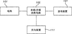
To be that expression is proposed by the invention pass through the block diagram that parallel discharge and serial connection charge are controlled the main design of rechargeable battery to Fig. 3.
Fig. 4 is the schematic diagram of closed loop circuit of the present invention.
Fig. 5 a is the circuit diagram that battery unit is connected by switching manipulation.
Fig. 5 b is the circuit diagram of battery unit quilt parallel connection by switching manipulation.
Fig. 6 has illustrated the situation according to battery control device operation of the present invention.
Embodiment
With preferred embodiment the present invention is described in detail below with reference to the accompanying drawings.
Preferred embodiment 1
Fig. 2 a has shown a controller according to rechargeable battery of the present invention.The shown core dimensions of the present invention of this figure is its control module and control method, its objective is by being connected in parallel to make rechargeable battery reach balanced.Related in this preferred embodiment is a kind of rechargeable battery, in other words, is that a kind of at least one or more battery units of containing is as one group reserve battery.In general, this reserve battery its objective is the use that is together in series of two, three, four, five, six, eight or ten battery units in order to obtain suitable electromotive force and accepts use with supply equipment.The situation that is to use four battery unit 101a, 101b, 101c and 101d that illustrates in this preferred embodiment, these battery units generally all are used in photoflash lamp, the diving of digital camera, camera and use among photoflash lamp and the toy.In four secondary battery unit 101a, 101b, 101c and 101d at least one reaches under the situation of final discharging voltage, and when this reserve battery installed on the equipment, it just need recharge.After on battery unit 101a, 101b, 101c and 101d slave unit, separating, they are connected in parallel.Then, electrical load device 123 and battery unit 101a, 101b, 101c and 101d are connected between two electrodes of battery unit 101a, the 101b, 101c and the 101d that are connected in parallel with being in parallel, and this electrical load device 123 has and the corresponding to normal voltage of battery unit electromotive force.Consequently, form all discharges simultaneously of each battery unit 101a, 101b, 101c and 101d of reserve battery.Has different voltage statuss owing to form battery unit 101a, 101b, 101c and the 101d of this public reserve battery.Therefore,, just can make them reach balanced, in other words, make the voltage of each battery unit 101a, 101b, 101c and 101d reach identical exactly with discharge if after they are connected in parallel, discharge again.At the parallel discharge that carries out a determining time so that after each battery unit reaches equilibrium, just can be by linking to each other with the serial connection charge circuit with to each battery unit charging.The time that is consumed when utilizing parallel discharge that rechargeable battery is controlled according to the difference of reserve battery situation and difference.Required time of the general final discharging voltage that preferably will reach the reserve battery that is connected in parallel is as the control time.Therefore, can use the corresponding to silicon diode 125 of a minimum break-down voltage (threshold voltage) and the summation of the final discharging voltage of reserve battery to be connected in parallel, shown in Fig. 2 b with battery unit 101a, 101b, 101c and 101d.In another approach, a timer 127 can be installed to be used for to carrying out Artificial Control discharge time, shown in Fig. 2 c.In our experience, when discharge than being 1C to 2C when (1C represents its charge or discharge capacity of 1 hour), just can reach effective control in 3 to 5 minutes by discharging.
Rechargeable battery of the present invention consists essentially of with lower unit: battery case 103, it can with battery unit 101a, 101b, 101c and 101d, that is, a plurality of rechargeable batteries are electrically connected, to be used to carry out the control method of rechargeable battery.Battery unit 101a, 101b, 101c and 101d can be used by series connection, so just can obtain the required electromotive force of electronic equipment; One closed loop circuit device 105, it and battery unit 101a, 101b, 101c and 101d are connected in parallel; One is in the electrical load device 123 among the closed loop circuit device 105, and it is connected in parallel between the two ends of battery unit 101a, 101b, 101c and 101d and has and the corresponding to normal voltage of battery unit electromotive force.Electrical load device 123 can adopt the device that is similar to resistance, bulb and electro-motor and so on, and these devices all can consume and the corresponding to normal voltage of battery unit electromotive force; One discharge blocking swtich 125, it is connected with electrical load device 123 and is in parallel with battery unit 101a, 101b, 101c and 101d, its objective is for the further discharge after preventing to finish discharge when beginning as in parallel battery unit 101a, 101b, 101c and 101d to discharge and reaching its final discharging voltage.Preferably adopt the corresponding to silicon diode of final discharging voltage (that is the final discharging voltage summation of Bing Lian each battery unit) to be used as this discharge blocking swtich 125 with minimum break-down voltage (threshold voltage) and reserve battery.
Preferred embodiment 2
The control device and the control method thereof that are used for the rechargeable battery of forming reserve battery is carried out parallel discharge that preferred embodiment 1 is illustrated, its effect are in order to carry out equilibrium before charging fully.Illustrated in this preferred embodiment then is a kind of control device and control method thereof that is used to contain the rechargeable battery of charge function.Fig. 3 has demonstrated a kind of basic design structure that is used for the control device of controlling according to the described rechargeable battery of this preferred embodiment.
At first, need one and contain one or more battery units with rechargeable battery 101 as one group.This rechargeable battery 101 links to each other with a closed loop circuit 105, and closed loop circuit 105 contains the switch 107 that can select between series connection and parallel connection.Selector switch 107 preferably links to each other with a battery condition testing apparatus, so that select series connection or in parallel according to the voltage condition of rechargeable battery 101.If rechargeable battery 101 selected switches 107 are connected in parallel, then rechargeable battery will be connected with an electric discharge device 123, and the electromotive force of a battery unit between the normal voltage that electric discharge device 123 is had and battery 101 two ends is consistent.Can send signal after discharge is performed a determining time preferably is connected between selector switch 107 and the electric discharge device 123 with the timer 127 that becomes to be connected in series that shifts gears of the connection with rechargeable battery 101.After parallel discharge is carried out a determining time according to the signal of timer 127, one is used for connected mode being converted to the charging device 111 that rechargeable battery 101 is charged after being connected in series at selector switch 107 will be access in closed loop circuit 105.
Below will the object lesson of present embodiment be described.Need one and contain one or more battery units with reserve battery as one group.In general, this reserve battery its objective is the use that is together in series of two, three, four, five, six, eight or ten battery units in order to obtain suitable electromotive force and uses with supply equipment.Why introduced the situation of using four battery units in the present embodiment once more, be because it has obtained using the most widely as an example with it.This reserve battery comprises battery case 103, and they can be electrically connected with battery unit 101a, 101b, 101c and 101d.One closed loop circuit 105 links to each other with battery case 103, and it is can be by the lead that utilizes electric wire and so in parallel or be together in series with battery unit 101a, 101b, 101c and 101d.Include a selector switch 107 in the closed loop circuit 105, it can select battery unit 101a, 101b, 101c and 101d to be connected in series or to be connected in parallel.Selector switch 107 can or be similar to the semiconductor device of MOSFET (mos field effect transistor) from rotary switch, relay and select.According to selector switch 107 selected connected modes, if battery unit 101a, 101b, 101c and 101d are connected in series, then the two ends of two 101b, the 101c of battery unit 101a, 101b, 101c and 101d and 101d all link to each other with charging device 111, if battery unit 101a, 101b, 101c and 101d are connected in parallel, then the two ends of battery unit 101a, 101b, 101c and 101d all link to each other with electric discharge device 121.Fig. 4 has demonstrated an example of closed loop circuit 105, and this circuit is designed to and can be connected in series or be connected in parallel.Fig. 5 a has shown the circuit when battery unit is connected in series by switching manipulation, and Fig. 5 b has then shown the circuit when battery unit is connected in parallel by switching manipulation.
Below will control method that utilize the said equipment that rechargeable battery is controlled be described.Fig. 6 has shown the operating conditions according to battery control device of the present invention.In Fig. 6, closed loop circuit 105 is connected in series battery unit 101a, 101b, 101c and 101d at starting stage 6a, then shown in the stage 6b among Fig. 6, to testing, and check whether it is lower than voltage available with the electromotive force of closed loop circuit 105 series connected battery unit 101a, 101b, 101c and 101d.If its electromotive force is lower than voltage available, then selector switch 107 will change over the connected mode of battery unit 101a, 101b, 101c and 101d and be connected in parallel, shown in the stage 6c among Fig. 6.Then, battery unit 101a, 101b, 101c and 101d will be carried out parallel discharge by electric discharge device 123, shown in the stage 6d among Fig. 6.
Required time of parallel discharge, timer 127 was installed between electric discharge device 123 and the selector switch 107 by a timer 127 automatic settings.Consider from battery being controlled the required time, preferably be set at discharge time within 5 minutes, shown in the stage 6e among Fig. 6.When timer 127 being used to of sending illustrates that signal that parallel discharge has been done is transmitted to selector switch 107, the connected mode of battery unit 101a, 101b, 101c and 101d will be changed and become to be connected in series, shown in the stage 6f among Fig. 6.Then, battery unit 101a, 101b, 101c and 101d are connected in series with charging device 111, and will carry out charging operations, shown in the stage 6g among Fig. 6.Should keep electromotive force is monitored when charging, if electromotive force is equal to or greater than the working voltage shown in the stage 6b among Fig. 6, then charging be stopped and operates the standby mode that will enter shown in the stage 6h among Fig. 6 always.
Under situation about recharging, in order to carry out high speed charging, the parallel discharge that can carry out 3 to 5 minutes to be controlling, and is about in charge ratio under the situation of 3C-4C and carries out discharge.Its result makes charging to finish within 30 minutes.
The present invention provides a kind of control device for rechargeable battery and has been used to control the method for rechargeable battery, this control device can be together in series to charge by the similar rechargeable battery that will have different power level after the rechargeable battery that is connected in parallel is carried out discharge.According to of the present invention,, just can carry out the high speed charging to the rechargeable battery that has identical energy level because of parallel discharge by the rechargeable battery that is in incomplete discharged condition is being carried out recharging after the equilibrium treatment.Because of overcharging and the impaired rechargeable battery of over-discharge can also can obtain recycling in the process of carrying out equilibrium treatment by parallel discharge.At last, though carried out multiple control and discharge by battery control device of the present invention, along with the control that repeats to battery, it also makes the durability of rechargeable battery obtain prolongation.
Claims (8)
1. control device that is used for rechargeable battery comprises:
Can be electrically connected the cell fixing device of battery unit;
The closed-loop device that is connected with the cell fixing device that contains the battery unit that is connected in parallel;
Be in electric discharge device among the closed-loop device, that be connected in parallel with the battery unit that is connected in parallel, it comprises that one has the electrical load with the corresponding to normal voltage of battery unit electromotive force.
2. the control device that is used for rechargeable battery according to claim 1 also comprises the discharge blocking swtich, and itself and described electric discharge device are connected in series, and are connected in parallel with battery unit.
3. the control device that is used for rechargeable battery according to claim 2 is characterized in that, the discharge blocking swtich is a minimum break-down voltage and the corresponding to silicon diode of final discharging voltage sum of the battery unit that is connected in parallel.
4. control device that is used for rechargeable battery comprises:
Can be electrically connected the cell fixing device of battery unit;
At least the closed loop circuit device that is connected with a kind of and cell fixing device that contains the battery unit that is connected in parallel in the serial or parallel connection dual mode;
The selector switch that is connected with the closed loop circuit device is for battery unit is selected at least a in two kinds of connected modes of serial or parallel connection;
Electric discharge device, if battery unit is connected in parallel, then itself and these battery unit is connected in parallel, described electric discharge device comprises that one has the electrical load with the corresponding to normal voltage of battery unit electromotive force; With
Charging device, if battery unit is connected in series, then itself and these battery unit is connected in series.
5. the control device that is used for rechargeable battery according to claim 4 also comprises a timer, and it determines discharge time when electric discharge device discharges to the battery unit that is connected in parallel.
6. the control device that is used for rechargeable battery according to claim 4 is characterized in that, described selector switch comprises at least from relay, rotary switch and comprises select the group of switching elements of thyristor a kind of.
7. a control method that is used for rechargeable battery comprises the steps:
At least two battery units are connected in parallel; With
Battery unit is parallel-connected on the electric discharge device that battery unit is discharged, and this electric discharge device has with the corresponding to normal voltage of battery unit maximum output voltage and with the battery unit that is connected in parallel and is connected in parallel.
8. a control method that is used for rechargeable battery comprises the steps:
At least two battery units are connected in series;
By checking the electromotive force of battery unit, determine whether the electromotive force of battery unit is lower than spendable voltage;
If the electromotive force of battery unit is lower than spendable voltage, battery unit is connected in parallel, and has the parallel discharge that carries out a scheduled time with the electric discharge device of the corresponding to normal voltage of battery unit maximum output voltage by being connected to; With
By being become the state of being connected in series, battery unit recharges.
Applications Claiming Priority (2)
| Application Number | Priority Date | Filing Date | Title |
|---|---|---|---|
| KR19990005042 | 1999-02-12 | ||
| KR0005042/1999 | 1999-02-12 |
Publications (2)
| Publication Number | Publication Date |
|---|---|
| CN1263364A CN1263364A (en) | 2000-08-16 |
| CN1146066C true CN1146066C (en) | 2004-04-14 |
Family
ID=19574247
Family Applications (1)
| Application Number | Title | Priority Date | Filing Date |
|---|---|---|---|
| CNB00100784XA Expired - Fee Related CN1146066C (en) | 1999-02-12 | 2000-02-12 | Control system of chargeable battery and its control method |
Country Status (9)
| Country | Link |
|---|---|
| US (1) | US6351097B1 (en) |
| JP (1) | JP2000232738A (en) |
| KR (1) | KR20000057966A (en) |
| CN (1) | CN1146066C (en) |
| AU (1) | AU1639000A (en) |
| DE (1) | DE10006420A1 (en) |
| FR (1) | FR2789819B1 (en) |
| GB (1) | GB2348748B (en) |
| HK (1) | HK1028844A1 (en) |
Families Citing this family (33)
| Publication number | Priority date | Publication date | Assignee | Title |
|---|---|---|---|---|
| GB2360148A (en) * | 2000-03-06 | 2001-09-12 | Richard Thomas Morgan | Individual charging of cells in a rechargeable battery |
| US7459882B2 (en) * | 2000-03-06 | 2008-12-02 | Richard Morgan | Rechargeable batteries |
| KR100459991B1 (en) * | 2002-04-10 | 2004-12-04 | 오우석 | A Management System for The Rechargerble Battery |
| KR100451637B1 (en) * | 2002-06-18 | 2004-10-08 | 오세광 | A Management System for the Rechargeable Battery |
| US7193392B2 (en) | 2002-11-25 | 2007-03-20 | Tiax Llc | System and method for determining and balancing state of charge among series connected electrical energy storage units |
| KR100569016B1 (en) * | 2004-03-11 | 2006-04-07 | 현대자동차주식회사 | Voltage balance control device of energy storage system for hybrid type |
| US20080259551A1 (en) * | 2007-04-20 | 2008-10-23 | Gotive A.S. | Modular computing device |
| KR101107999B1 (en) | 2007-10-16 | 2012-01-25 | 한국과학기술원 | Battery Management System with Integration of Voltage Sensor and Charge Equalizer |
| KR101220339B1 (en) | 2007-10-16 | 2013-01-09 | 한국과학기술원 | Automatic Charge Equalization Method and Apparatus for Series Connected Battery String |
| KR101164629B1 (en) | 2007-10-16 | 2012-07-11 | 한국과학기술원 | Two-Stage Charge Equalization Method and Apparatus for Series-Connected Battery String |
| CN101593854B (en) * | 2008-05-26 | 2011-07-27 | 台湾神户电池股份有限公司 | Battery charging and discharging device |
| TWI366967B (en) * | 2008-12-11 | 2012-06-21 | Stl Technology Co Ltd | A removable and short-circuit-avoidable lithium battery module |
| FR2947112A1 (en) * | 2009-10-29 | 2010-12-24 | Commissariat Energie Atomique | Accumulators e.g. lithium-iron-phosphate accumulators, battery recharging device for e.g. hybrid motor vehicle, has control module to control connections of accumulators in series and application of current on accumulators in charging mode |
| JP5484860B2 (en) * | 2009-10-30 | 2014-05-07 | 株式会社マキタ | Power supply |
| US9293935B2 (en) | 2010-11-02 | 2016-03-22 | Navitas Solutions, Inc. | Wireless battery area network for a smart battery management system |
| US9564762B2 (en) | 2010-11-02 | 2017-02-07 | Navitas Solutions | Fault tolerant wireless battery area network for a smart battery management system |
| US9559530B2 (en) | 2010-11-02 | 2017-01-31 | Navitas Solutions | Fault tolerant wireless battery area network for a smart battery management system |
| CN102201690A (en) * | 2011-05-18 | 2011-09-28 | 肇庆理士电源技术有限公司 | Extensive using method of charging and discharging motor |
| US9553463B2 (en) * | 2011-10-12 | 2017-01-24 | Mechanical Energy Generating Systems, L.L.C. | Systems, methods, and apparatus for a homopolar generator charger with integral rechargeable battery |
| CN102738430A (en) * | 2012-05-09 | 2012-10-17 | 刘跨云 | Quick-charge storage battery |
| JP2013240219A (en) * | 2012-05-16 | 2013-11-28 | Sharp Corp | Storage battery system and storage battery system construction method |
| JP5867345B2 (en) * | 2012-09-03 | 2016-02-24 | カシオ計算機株式会社 | Charging apparatus and charging method |
| JP5660105B2 (en) * | 2012-10-24 | 2015-01-28 | トヨタ自動車株式会社 | Power storage system |
| JP5611400B2 (en) * | 2013-03-27 | 2014-10-22 | 三菱重工業株式会社 | Battery system for industrial machinery |
| CA2900271A1 (en) * | 2014-08-21 | 2016-02-21 | Johnson & Johnson Vision Care, Inc. | Components with multiple energization elements for biomedical devices |
| CN104578310A (en) * | 2015-01-23 | 2015-04-29 | 深圳市沃特玛电池有限公司 | Battery set energy balance circuit |
| CN105978049A (en) * | 2015-10-26 | 2016-09-28 | 乐视移动智能信息技术(北京)有限公司 | Battery voltage-multiplying charging circuit and mobile terminal |
| DE102016207272A1 (en) * | 2016-04-28 | 2017-11-02 | Bayerische Motoren Werke Aktiengesellschaft | Switchable storage system for a vehicle |
| DE102016224005A1 (en) * | 2016-12-02 | 2018-06-07 | Audi Ag | Electrical energy storage device |
| CN106696748B (en) * | 2017-01-25 | 2019-06-28 | 华为技术有限公司 | A kind of charging pile system |
| FR3067861B1 (en) * | 2017-06-14 | 2021-12-17 | Peugeot Citroen Automobiles Sa | HYBRID OR ELECTRIC VEHICLE BATTERY CONTAINING SWITCHES FOR ADAPTATION TO A CHARGER |
| US9800719B1 (en) * | 2017-07-11 | 2017-10-24 | Premergy, Inc. | Systems and methods for managing power for a mobile device |
| DE102021210037A1 (en) | 2021-09-10 | 2023-03-16 | Volkswagen Aktiengesellschaft | Method for operating a rechargeable lithium-containing and/or sodium-containing battery |
Family Cites Families (12)
| Publication number | Priority date | Publication date | Assignee | Title |
|---|---|---|---|---|
| GB1428661A (en) * | 1972-03-15 | 1976-03-17 | Varta Great Britain Ltd | Stand-by electric power supply units |
| GB1461616A (en) | 1973-04-10 | 1977-01-13 | Mabuchi Motor Co | Battery equalizing discharger |
| CH608661A5 (en) * | 1977-04-01 | 1979-01-15 | Leclanche Sa | Device comprising a number N of electric accumulators of like voltage and like capacitance |
| US4303877A (en) * | 1978-05-05 | 1981-12-01 | Brown, Boveri & Cie Aktiengesellschaft | Circuit for protecting storage cells |
| SG49780A1 (en) * | 1992-03-16 | 1998-06-15 | 4C Technologies Inc | Apparatus and method of rapidly charging nickel - cadmium battery |
| US5356343A (en) * | 1992-07-29 | 1994-10-18 | Lovetere Christopher J | Flash magic wand |
| JPH07212980A (en) * | 1994-01-13 | 1995-08-11 | Fujitsu Ltd | Battery charging and discharging device |
| JPH08340641A (en) * | 1995-06-12 | 1996-12-24 | Tokyo R & D:Kk | Battery power circuit |
| JPH09140065A (en) * | 1995-11-10 | 1997-05-27 | Sony Corp | Secondary battery for parallel use |
| KR0137758Y1 (en) * | 1995-11-16 | 1999-05-15 | 한승준 | Battery overcharging protection apparatus of an electric vehicle |
| GB2358300B (en) * | 1997-02-10 | 2001-08-29 | Nec Corp | Portable electronic device and battery pack |
| US6057670A (en) * | 1998-11-04 | 2000-05-02 | Saft America, Inc. | Smart connector for rechargeable battery |
-
2000
- 2000-02-08 KR KR1020000005820A patent/KR20000057966A/en not_active IP Right Cessation
- 2000-02-11 FR FR0001763A patent/FR2789819B1/en not_active Expired - Fee Related
- 2000-02-11 GB GB0003253A patent/GB2348748B/en not_active Expired - Fee Related
- 2000-02-12 CN CNB00100784XA patent/CN1146066C/en not_active Expired - Fee Related
- 2000-02-14 US US09/503,250 patent/US6351097B1/en not_active Expired - Fee Related
- 2000-02-14 DE DE10006420A patent/DE10006420A1/en not_active Withdrawn
- 2000-02-14 JP JP2000035554A patent/JP2000232738A/en active Pending
- 2000-02-14 AU AU16390/00A patent/AU1639000A/en not_active Abandoned
- 2000-11-17 HK HK00107362A patent/HK1028844A1/en not_active IP Right Cessation
Also Published As
| Publication number | Publication date |
|---|---|
| GB0003253D0 (en) | 2000-04-05 |
| FR2789819A1 (en) | 2000-08-18 |
| HK1028844A1 (en) | 2001-03-02 |
| DE10006420A1 (en) | 2000-08-31 |
| GB2348748B (en) | 2003-09-24 |
| FR2789819B1 (en) | 2002-09-27 |
| GB2348748A (en) | 2000-10-11 |
| KR100339119B1 (en) | 2002-05-31 |
| JP2000232738A (en) | 2000-08-22 |
| AU1639000A (en) | 2000-08-24 |
| US6351097B1 (en) | 2002-02-26 |
| CN1263364A (en) | 2000-08-16 |
| KR20000057966A (en) | 2000-09-25 |
Similar Documents
| Publication | Publication Date | Title |
|---|---|---|
| CN1146066C (en) | Control system of chargeable battery and its control method | |
| CN100533912C (en) | Systems and methods for regulating pre-charge current in a battery system | |
| EP1201006B1 (en) | Rechargeable battery packs | |
| JP3869585B2 (en) | Discharge method of multiple secondary batteries and assembled battery | |
| US3930192A (en) | Stand-by power system | |
| CN1307742C (en) | Back-up battery for cellular telephone | |
| EP1187296A2 (en) | Intelligent power management for rechargeable batteries | |
| JPH09121461A (en) | Self-charging battery and electric apparatus employing it | |
| CN1659758A (en) | Charger for rechargeable batteries | |
| JP2003157908A (en) | Charging device for lithium ion secondary cell, and charging method of the same | |
| JP2014515251A (en) | Low cost quick charger and method with internal accumulator | |
| JP2000150001A (en) | Smart connector for rechargeable battery | |
| US20120161564A1 (en) | Device and Method of Recycling Energy | |
| JPH0956056A (en) | Secondary-battery power unit, protective circuit, and method for protecting secondary battery from being abnormally charged | |
| JP2002078229A (en) | Charging/discharging device for secondary battery | |
| US6337555B1 (en) | Manage system of rechargeable battery and a method for managing thereof | |
| JPH08241705A (en) | Battery | |
| JP3421534B2 (en) | Overcharge prevention circuit, overdischarge prevention circuit and charge / discharge control circuit | |
| KR100459991B1 (en) | A Management System for The Rechargerble Battery | |
| JPH11146570A (en) | Control device of secondary battery, battery pack with the control device of secondary battery and control method of the secondary battery | |
| TW523947B (en) | A manage system of rechargeable battery and a method for managing thereof | |
| JPH06111852A (en) | Battery system | |
| JP2006340451A (en) | Charging method and charger | |
| KR200211543Y1 (en) | battery device | |
| JPH11185824A (en) | Primary battery compatible battery pack |
Legal Events
| Date | Code | Title | Description |
|---|---|---|---|
| C10 | Entry into substantive examination | ||
| SE01 | Entry into force of request for substantive examination | ||
| C06 | Publication | ||
| PB01 | Publication | ||
| C14 | Grant of patent or utility model | ||
| GR01 | Patent grant | ||
| REG | Reference to a national code |
Ref country code: HK Ref legal event code: GR Ref document number: 1028844 Country of ref document: HK |
|
| C19 | Lapse of patent right due to non-payment of the annual fee | ||
| CF01 | Termination of patent right due to non-payment of annual fee |