CN114599318A - Expandable sheath for introducing intravascular delivery devices into the body - Google Patents
Expandable sheath for introducing intravascular delivery devices into the body Download PDFInfo
- Publication number
- CN114599318A CN114599318A CN202180006107.5A CN202180006107A CN114599318A CN 114599318 A CN114599318 A CN 114599318A CN 202180006107 A CN202180006107 A CN 202180006107A CN 114599318 A CN114599318 A CN 114599318A
- Authority
- CN
- China
- Prior art keywords
- sheath
- sheet
- aspects
- layer
- inner liner
- Prior art date
- Legal status (The legal status is an assumption and is not a legal conclusion. Google has not performed a legal analysis and makes no representation as to the accuracy of the status listed.)
- Pending
Links
- 230000000284 resting effect Effects 0.000 claims abstract description 102
- 229920000642 polymer Polymers 0.000 claims description 644
- 239000000314 lubricant Substances 0.000 claims description 274
- 239000000463 material Substances 0.000 claims description 251
- 239000002131 composite material Substances 0.000 claims description 169
- 239000000203 mixture Substances 0.000 claims description 94
- 239000000945 filler Substances 0.000 claims description 75
- 229920002635 polyurethane Polymers 0.000 claims description 73
- 239000004814 polyurethane Substances 0.000 claims description 73
- 229920001971 elastomer Polymers 0.000 claims description 39
- 239000000806 elastomer Substances 0.000 claims description 37
- 239000011256 inorganic filler Substances 0.000 claims description 37
- 229910003475 inorganic filler Inorganic materials 0.000 claims description 37
- 229920001577 copolymer Polymers 0.000 claims description 36
- 229920002614 Polyether block amide Polymers 0.000 claims description 35
- 238000000576 coating method Methods 0.000 claims description 28
- 239000007787 solid Substances 0.000 claims description 28
- 229920000098 polyolefin Polymers 0.000 claims description 27
- 230000001050 lubricating effect Effects 0.000 claims description 23
- 150000001875 compounds Chemical class 0.000 claims description 19
- 239000011248 coating agent Substances 0.000 claims description 17
- 229920000126 latex Polymers 0.000 claims description 16
- 239000004816 latex Substances 0.000 claims description 16
- TZCXTZWJZNENPQ-UHFFFAOYSA-L barium sulfate Chemical compound [Ba+2].[O-]S([O-])(=O)=O TZCXTZWJZNENPQ-UHFFFAOYSA-L 0.000 claims description 12
- VTYYLEPIZMXCLO-UHFFFAOYSA-L Calcium carbonate Chemical compound [Ca+2].[O-]C([O-])=O VTYYLEPIZMXCLO-UHFFFAOYSA-L 0.000 claims description 8
- 229910000014 Bismuth subcarbonate Inorganic materials 0.000 claims description 6
- MGLUJXPJRXTKJM-UHFFFAOYSA-L bismuth subcarbonate Chemical compound O=[Bi]OC(=O)O[Bi]=O MGLUJXPJRXTKJM-UHFFFAOYSA-L 0.000 claims description 6
- 229940036358 bismuth subcarbonate Drugs 0.000 claims description 6
- 239000005995 Aluminium silicate Substances 0.000 claims description 4
- 235000019738 Limestone Nutrition 0.000 claims description 4
- RREGISFBPQOLTM-UHFFFAOYSA-N alumane;trihydrate Chemical compound O.O.O.[AlH3] RREGISFBPQOLTM-UHFFFAOYSA-N 0.000 claims description 4
- 235000012211 aluminium silicate Nutrition 0.000 claims description 4
- 229940092690 barium sulfate Drugs 0.000 claims description 4
- 239000010428 baryte Substances 0.000 claims description 4
- 229910052601 baryte Inorganic materials 0.000 claims description 4
- 229940073609 bismuth oxychloride Drugs 0.000 claims description 4
- 229910000019 calcium carbonate Inorganic materials 0.000 claims description 4
- 229960003563 calcium carbonate Drugs 0.000 claims description 4
- NLYAJNPCOHFWQQ-UHFFFAOYSA-N kaolin Chemical compound O.O.O=[Al]O[Si](=O)O[Si](=O)O[Al]=O NLYAJNPCOHFWQQ-UHFFFAOYSA-N 0.000 claims description 4
- 239000006028 limestone Substances 0.000 claims description 4
- BWOROQSFKKODDR-UHFFFAOYSA-N oxobismuth;hydrochloride Chemical compound Cl.[Bi]=O BWOROQSFKKODDR-UHFFFAOYSA-N 0.000 claims description 4
- 208000027418 Wounds and injury Diseases 0.000 abstract description 12
- 210000003709 heart valve Anatomy 0.000 abstract description 9
- 208000014674 injury Diseases 0.000 abstract description 8
- 230000008733 trauma Effects 0.000 abstract description 6
- 239000010410 layer Substances 0.000 description 1124
- 238000000034 method Methods 0.000 description 342
- 230000003014 reinforcing effect Effects 0.000 description 114
- 230000000670 limiting effect Effects 0.000 description 46
- 238000004519 manufacturing process Methods 0.000 description 41
- 229910001000 nickel titanium Inorganic materials 0.000 description 38
- HLXZNVUGXRDIFK-UHFFFAOYSA-N nickel titanium Chemical compound [Ti].[Ti].[Ti].[Ti].[Ti].[Ti].[Ti].[Ti].[Ti].[Ti].[Ti].[Ni].[Ni].[Ni].[Ni].[Ni].[Ni].[Ni].[Ni].[Ni].[Ni].[Ni].[Ni].[Ni].[Ni] HLXZNVUGXRDIFK-UHFFFAOYSA-N 0.000 description 38
- 210000004204 blood vessel Anatomy 0.000 description 37
- 239000004810 polytetrafluoroethylene Substances 0.000 description 37
- 238000005096 rolling process Methods 0.000 description 37
- 229920001343 polytetrafluoroethylene Polymers 0.000 description 36
- 238000003780 insertion Methods 0.000 description 26
- 230000037431 insertion Effects 0.000 description 26
- 238000005520 cutting process Methods 0.000 description 24
- 239000013536 elastomeric material Substances 0.000 description 23
- 239000010935 stainless steel Substances 0.000 description 22
- 229910001220 stainless steel Inorganic materials 0.000 description 22
- 230000023597 hemostasis Effects 0.000 description 21
- -1 polypropylene Polymers 0.000 description 20
- 238000007906 compression Methods 0.000 description 18
- 230000006835 compression Effects 0.000 description 18
- 230000002787 reinforcement Effects 0.000 description 18
- 210000005166 vasculature Anatomy 0.000 description 16
- 229920001903 high density polyethylene Polymers 0.000 description 15
- 239000004700 high-density polyethylene Substances 0.000 description 15
- 229920000728 polyester Polymers 0.000 description 15
- 238000003466 welding Methods 0.000 description 15
- 230000009977 dual effect Effects 0.000 description 14
- 238000005461 lubrication Methods 0.000 description 13
- 239000004677 Nylon Substances 0.000 description 12
- 239000004952 Polyamide Substances 0.000 description 12
- 229920001778 nylon Polymers 0.000 description 12
- 229920002647 polyamide Polymers 0.000 description 12
- 229920002313 fluoropolymer Polymers 0.000 description 11
- 239000004811 fluoropolymer Substances 0.000 description 11
- 230000008569 process Effects 0.000 description 11
- 239000000654 additive Substances 0.000 description 10
- 238000001125 extrusion Methods 0.000 description 10
- 238000010438 heat treatment Methods 0.000 description 10
- 238000009434 installation Methods 0.000 description 10
- 238000007649 pad printing Methods 0.000 description 10
- 239000004743 Polypropylene Substances 0.000 description 9
- 210000003484 anatomy Anatomy 0.000 description 9
- 230000008878 coupling Effects 0.000 description 9
- 238000010168 coupling process Methods 0.000 description 9
- 238000005859 coupling reaction Methods 0.000 description 9
- 229910052751 metal Inorganic materials 0.000 description 9
- 239000002184 metal Substances 0.000 description 9
- 229920001155 polypropylene Polymers 0.000 description 9
- 229920001296 polysiloxane Polymers 0.000 description 9
- 230000000996 additive effect Effects 0.000 description 8
- 238000009998 heat setting Methods 0.000 description 8
- BASFCYQUMIYNBI-UHFFFAOYSA-N platinum Chemical compound [Pt] BASFCYQUMIYNBI-UHFFFAOYSA-N 0.000 description 8
- 230000007423 decrease Effects 0.000 description 7
- 230000001788 irregular Effects 0.000 description 7
- 239000013047 polymeric layer Substances 0.000 description 7
- 229920001897 terpolymer Polymers 0.000 description 7
- 230000036772 blood pressure Effects 0.000 description 6
- 238000010586 diagram Methods 0.000 description 6
- 230000000694 effects Effects 0.000 description 6
- 230000006870 function Effects 0.000 description 6
- 238000001356 surgical procedure Methods 0.000 description 6
- 239000004698 Polyethylene Substances 0.000 description 5
- 239000004744 fabric Substances 0.000 description 5
- FPYJFEHAWHCUMM-UHFFFAOYSA-N maleic anhydride Chemical compound O=C1OC(=O)C=C1 FPYJFEHAWHCUMM-UHFFFAOYSA-N 0.000 description 5
- 230000036961 partial effect Effects 0.000 description 5
- 229920000573 polyethylene Polymers 0.000 description 5
- 238000005507 spraying Methods 0.000 description 5
- 230000007704 transition Effects 0.000 description 5
- OKTJSMMVPCPJKN-UHFFFAOYSA-N Carbon Chemical compound [C] OKTJSMMVPCPJKN-UHFFFAOYSA-N 0.000 description 4
- 239000004812 Fluorinated ethylene propylene Substances 0.000 description 4
- GWEVSGVZZGPLCZ-UHFFFAOYSA-N Titan oxide Chemical compound O=[Ti]=O GWEVSGVZZGPLCZ-UHFFFAOYSA-N 0.000 description 4
- 230000006378 damage Effects 0.000 description 4
- HQQADJVZYDDRJT-UHFFFAOYSA-N ethene;prop-1-ene Chemical group C=C.CC=C HQQADJVZYDDRJT-UHFFFAOYSA-N 0.000 description 4
- 239000000835 fiber Substances 0.000 description 4
- 229910021389 graphene Inorganic materials 0.000 description 4
- 238000002513 implantation Methods 0.000 description 4
- 239000004615 ingredient Substances 0.000 description 4
- 229920001684 low density polyethylene Polymers 0.000 description 4
- 239000004702 low-density polyethylene Substances 0.000 description 4
- 239000003550 marker Substances 0.000 description 4
- 229920009441 perflouroethylene propylene Polymers 0.000 description 4
- 239000002861 polymer material Substances 0.000 description 4
- 239000000843 powder Substances 0.000 description 4
- 230000002829 reductive effect Effects 0.000 description 4
- 239000002033 PVDF binder Substances 0.000 description 3
- 210000001367 artery Anatomy 0.000 description 3
- 230000008901 benefit Effects 0.000 description 3
- 210000003445 biliary tract Anatomy 0.000 description 3
- 239000008280 blood Substances 0.000 description 3
- 210000004369 blood Anatomy 0.000 description 3
- 230000000916 dilatatory effect Effects 0.000 description 3
- 230000002124 endocrine Effects 0.000 description 3
- 210000003238 esophagus Anatomy 0.000 description 3
- 229920006242 ethylene acrylic acid copolymer Polymers 0.000 description 3
- 230000000977 initiatory effect Effects 0.000 description 3
- 210000000936 intestine Anatomy 0.000 description 3
- 238000002324 minimally invasive surgery Methods 0.000 description 3
- 210000003101 oviduct Anatomy 0.000 description 3
- 229920002981 polyvinylidene fluoride Polymers 0.000 description 3
- 230000008439 repair process Effects 0.000 description 3
- 239000007921 spray Substances 0.000 description 3
- 239000000126 substance Substances 0.000 description 3
- 238000012546 transfer Methods 0.000 description 3
- 210000003708 urethra Anatomy 0.000 description 3
- 230000002792 vascular Effects 0.000 description 3
- 210000003462 vein Anatomy 0.000 description 3
- KUDUQBURMYMBIJ-UHFFFAOYSA-N 2-prop-2-enoyloxyethyl prop-2-enoate Chemical compound C=CC(=O)OCCOC(=O)C=C KUDUQBURMYMBIJ-UHFFFAOYSA-N 0.000 description 2
- 229910052582 BN Inorganic materials 0.000 description 2
- PZNSFCLAULLKQX-UHFFFAOYSA-N Boron nitride Chemical compound N#B PZNSFCLAULLKQX-UHFFFAOYSA-N 0.000 description 2
- 101000955333 Homo sapiens Mediator of RNA polymerase II transcription subunit 10 Proteins 0.000 description 2
- 229910000575 Ir alloy Inorganic materials 0.000 description 2
- 102100038976 Mediator of RNA polymerase II transcription subunit 10 Human genes 0.000 description 2
- 239000004721 Polyphenylene oxide Substances 0.000 description 2
- 229910001260 Pt alloy Inorganic materials 0.000 description 2
- 239000004760 aramid Substances 0.000 description 2
- 229920006231 aramid fiber Polymers 0.000 description 2
- ARSLNKYOPNUFFY-UHFFFAOYSA-L barium sulfite Chemical compound [Ba+2].[O-]S([O-])=O ARSLNKYOPNUFFY-UHFFFAOYSA-L 0.000 description 2
- WMWLMWRWZQELOS-UHFFFAOYSA-N bismuth(III) oxide Inorganic materials O=[Bi]O[Bi]=O WMWLMWRWZQELOS-UHFFFAOYSA-N 0.000 description 2
- 239000006229 carbon black Substances 0.000 description 2
- 238000003486 chemical etching Methods 0.000 description 2
- 230000021615 conjugation Effects 0.000 description 2
- 238000013461 design Methods 0.000 description 2
- CQSOJTLWAIPPQL-UHFFFAOYSA-N ethene;oxiran-2-ylmethyl 2-methylprop-2-enoate;prop-2-enoic acid Chemical compound C=C.OC(=O)C=C.CC(=C)C(=O)OCC1CO1 CQSOJTLWAIPPQL-UHFFFAOYSA-N 0.000 description 2
- 229920006228 ethylene acrylate copolymer Polymers 0.000 description 2
- 210000001105 femoral artery Anatomy 0.000 description 2
- 239000012530 fluid Substances 0.000 description 2
- 238000001746 injection moulding Methods 0.000 description 2
- 229910052741 iridium Inorganic materials 0.000 description 2
- GKOZUEZYRPOHIO-UHFFFAOYSA-N iridium atom Chemical compound [Ir] GKOZUEZYRPOHIO-UHFFFAOYSA-N 0.000 description 2
- 230000007246 mechanism Effects 0.000 description 2
- 238000002844 melting Methods 0.000 description 2
- 230000008018 melting Effects 0.000 description 2
- 229910001092 metal group alloy Inorganic materials 0.000 description 2
- 150000002739 metals Chemical class 0.000 description 2
- 238000005457 optimization Methods 0.000 description 2
- 238000001020 plasma etching Methods 0.000 description 2
- 229910052697 platinum Inorganic materials 0.000 description 2
- 229920000570 polyether Polymers 0.000 description 2
- 229920001195 polyisoprene Polymers 0.000 description 2
- 239000004800 polyvinyl chloride Substances 0.000 description 2
- 229920000915 polyvinyl chloride Polymers 0.000 description 2
- 229910001285 shape-memory alloy Inorganic materials 0.000 description 2
- 238000004381 surface treatment Methods 0.000 description 2
- 239000000454 talc Substances 0.000 description 2
- 229910052623 talc Inorganic materials 0.000 description 2
- 229920001187 thermosetting polymer Polymers 0.000 description 2
- 239000004408 titanium dioxide Substances 0.000 description 2
- 239000002759 woven fabric Substances 0.000 description 2
- VCGRFBXVSFAGGA-UHFFFAOYSA-N (1,1-dioxo-1,4-thiazinan-4-yl)-[6-[[3-(4-fluorophenyl)-5-methyl-1,2-oxazol-4-yl]methoxy]pyridin-3-yl]methanone Chemical compound CC=1ON=C(C=2C=CC(F)=CC=2)C=1COC(N=C1)=CC=C1C(=O)N1CCS(=O)(=O)CC1 VCGRFBXVSFAGGA-UHFFFAOYSA-N 0.000 description 1
- SOCAXRLFGRNEPK-IFZYUDKTSA-N (1r,3s,5r)-2-n-[1-carbamoyl-5-(cyanomethoxy)indol-3-yl]-3-n-[(3-chloro-2-fluorophenyl)methyl]-2-azabicyclo[3.1.0]hexane-2,3-dicarboxamide Chemical compound O=C([C@@H]1C[C@H]2C[C@H]2N1C(=O)NC1=CN(C2=CC=C(OCC#N)C=C21)C(=O)N)NCC1=CC=CC(Cl)=C1F SOCAXRLFGRNEPK-IFZYUDKTSA-N 0.000 description 1
- DOMQFIFVDIAOOT-ROUUACIJSA-N (2S,3R)-N-[4-(2,6-dimethoxyphenyl)-5-(5-methylpyridin-3-yl)-1,2,4-triazol-3-yl]-3-(5-methylpyrimidin-2-yl)butane-2-sulfonamide Chemical compound COC1=C(C(=CC=C1)OC)N1C(=NN=C1C=1C=NC=C(C=1)C)NS(=O)(=O)[C@@H](C)[C@H](C)C1=NC=C(C=N1)C DOMQFIFVDIAOOT-ROUUACIJSA-N 0.000 description 1
- MAYZWDRUFKUGGP-VIFPVBQESA-N (3s)-1-[5-tert-butyl-3-[(1-methyltetrazol-5-yl)methyl]triazolo[4,5-d]pyrimidin-7-yl]pyrrolidin-3-ol Chemical compound CN1N=NN=C1CN1C2=NC(C(C)(C)C)=NC(N3C[C@@H](O)CC3)=C2N=N1 MAYZWDRUFKUGGP-VIFPVBQESA-N 0.000 description 1
- HGRWHBQLRXWSLV-DEOSSOPVSA-N (4s)-3'-(3,6-dihydro-2h-pyran-5-yl)-1'-fluoro-7'-(3-fluoropyridin-2-yl)spiro[5h-1,3-oxazole-4,5'-chromeno[2,3-c]pyridine]-2-amine Chemical compound C1OC(N)=N[C@]21C1=CC(C=3COCCC=3)=NC(F)=C1OC1=CC=C(C=3C(=CC=CN=3)F)C=C12 HGRWHBQLRXWSLV-DEOSSOPVSA-N 0.000 description 1
- UKGJZDSUJSPAJL-YPUOHESYSA-N (e)-n-[(1r)-1-[3,5-difluoro-4-(methanesulfonamido)phenyl]ethyl]-3-[2-propyl-6-(trifluoromethyl)pyridin-3-yl]prop-2-enamide Chemical compound CCCC1=NC(C(F)(F)F)=CC=C1\C=C\C(=O)N[C@H](C)C1=CC(F)=C(NS(C)(=O)=O)C(F)=C1 UKGJZDSUJSPAJL-YPUOHESYSA-N 0.000 description 1
- ZGYIXVSQHOKQRZ-COIATFDQSA-N (e)-n-[4-[3-chloro-4-(pyridin-2-ylmethoxy)anilino]-3-cyano-7-[(3s)-oxolan-3-yl]oxyquinolin-6-yl]-4-(dimethylamino)but-2-enamide Chemical compound N#CC1=CN=C2C=C(O[C@@H]3COCC3)C(NC(=O)/C=C/CN(C)C)=CC2=C1NC(C=C1Cl)=CC=C1OCC1=CC=CC=N1 ZGYIXVSQHOKQRZ-COIATFDQSA-N 0.000 description 1
- MOWXJLUYGFNTAL-DEOSSOPVSA-N (s)-[2-chloro-4-fluoro-5-(7-morpholin-4-ylquinazolin-4-yl)phenyl]-(6-methoxypyridazin-3-yl)methanol Chemical compound N1=NC(OC)=CC=C1[C@@H](O)C1=CC(C=2C3=CC=C(C=C3N=CN=2)N2CCOCC2)=C(F)C=C1Cl MOWXJLUYGFNTAL-DEOSSOPVSA-N 0.000 description 1
- APWRZPQBPCAXFP-UHFFFAOYSA-N 1-(1-oxo-2H-isoquinolin-5-yl)-5-(trifluoromethyl)-N-[2-(trifluoromethyl)pyridin-4-yl]pyrazole-4-carboxamide Chemical compound O=C1NC=CC2=C(C=CC=C12)N1N=CC(=C1C(F)(F)F)C(=O)NC1=CC(=NC=C1)C(F)(F)F APWRZPQBPCAXFP-UHFFFAOYSA-N 0.000 description 1
- MJUVRTYWUMPBTR-MRXNPFEDSA-N 1-(2,2-difluoro-1,3-benzodioxol-5-yl)-n-[1-[(2r)-2,3-dihydroxypropyl]-6-fluoro-2-(1-hydroxy-2-methylpropan-2-yl)indol-5-yl]cyclopropane-1-carboxamide Chemical compound FC=1C=C2N(C[C@@H](O)CO)C(C(C)(CO)C)=CC2=CC=1NC(=O)C1(C=2C=C3OC(F)(F)OC3=CC=2)CC1 MJUVRTYWUMPBTR-MRXNPFEDSA-N 0.000 description 1
- ABDDQTDRAHXHOC-QMMMGPOBSA-N 1-[(7s)-5,7-dihydro-4h-thieno[2,3-c]pyran-7-yl]-n-methylmethanamine Chemical compound CNC[C@@H]1OCCC2=C1SC=C2 ABDDQTDRAHXHOC-QMMMGPOBSA-N 0.000 description 1
- HCDMJFOHIXMBOV-UHFFFAOYSA-N 3-(2,6-difluoro-3,5-dimethoxyphenyl)-1-ethyl-8-(morpholin-4-ylmethyl)-4,7-dihydropyrrolo[4,5]pyrido[1,2-d]pyrimidin-2-one Chemical compound C=1C2=C3N(CC)C(=O)N(C=4C(=C(OC)C=C(OC)C=4F)F)CC3=CN=C2NC=1CN1CCOCC1 HCDMJFOHIXMBOV-UHFFFAOYSA-N 0.000 description 1
- BYHQTRFJOGIQAO-GOSISDBHSA-N 3-(4-bromophenyl)-8-[(2R)-2-hydroxypropyl]-1-[(3-methoxyphenyl)methyl]-1,3,8-triazaspiro[4.5]decan-2-one Chemical compound C[C@H](CN1CCC2(CC1)CN(C(=O)N2CC3=CC(=CC=C3)OC)C4=CC=C(C=C4)Br)O BYHQTRFJOGIQAO-GOSISDBHSA-N 0.000 description 1
- YGYGASJNJTYNOL-CQSZACIVSA-N 3-[(4r)-2,2-dimethyl-1,1-dioxothian-4-yl]-5-(4-fluorophenyl)-1h-indole-7-carboxamide Chemical compound C1CS(=O)(=O)C(C)(C)C[C@@H]1C1=CNC2=C(C(N)=O)C=C(C=3C=CC(F)=CC=3)C=C12 YGYGASJNJTYNOL-CQSZACIVSA-N 0.000 description 1
- WNEODWDFDXWOLU-QHCPKHFHSA-N 3-[3-(hydroxymethyl)-4-[1-methyl-5-[[5-[(2s)-2-methyl-4-(oxetan-3-yl)piperazin-1-yl]pyridin-2-yl]amino]-6-oxopyridin-3-yl]pyridin-2-yl]-7,7-dimethyl-1,2,6,8-tetrahydrocyclopenta[3,4]pyrrolo[3,5-b]pyrazin-4-one Chemical compound C([C@@H](N(CC1)C=2C=NC(NC=3C(N(C)C=C(C=3)C=3C(=C(N4C(C5=CC=6CC(C)(C)CC=6N5CC4)=O)N=CC=3)CO)=O)=CC=2)C)N1C1COC1 WNEODWDFDXWOLU-QHCPKHFHSA-N 0.000 description 1
- SRVXSISGYBMIHR-UHFFFAOYSA-N 3-[3-[3-(2-amino-2-oxoethyl)phenyl]-5-chlorophenyl]-3-(5-methyl-1,3-thiazol-2-yl)propanoic acid Chemical compound S1C(C)=CN=C1C(CC(O)=O)C1=CC(Cl)=CC(C=2C=C(CC(N)=O)C=CC=2)=C1 SRVXSISGYBMIHR-UHFFFAOYSA-N 0.000 description 1
- VJPPLCNBDLZIFG-ZDUSSCGKSA-N 4-[(3S)-3-(but-2-ynoylamino)piperidin-1-yl]-5-fluoro-2,3-dimethyl-1H-indole-7-carboxamide Chemical compound C(C#CC)(=O)N[C@@H]1CN(CCC1)C1=C2C(=C(NC2=C(C=C1F)C(=O)N)C)C VJPPLCNBDLZIFG-ZDUSSCGKSA-N 0.000 description 1
- YFCIFWOJYYFDQP-PTWZRHHISA-N 4-[3-amino-6-[(1S,3S,4S)-3-fluoro-4-hydroxycyclohexyl]pyrazin-2-yl]-N-[(1S)-1-(3-bromo-5-fluorophenyl)-2-(methylamino)ethyl]-2-fluorobenzamide Chemical compound CNC[C@@H](NC(=O)c1ccc(cc1F)-c1nc(cnc1N)[C@H]1CC[C@H](O)[C@@H](F)C1)c1cc(F)cc(Br)c1 YFCIFWOJYYFDQP-PTWZRHHISA-N 0.000 description 1
- XYWIPYBIIRTJMM-IBGZPJMESA-N 4-[[(2S)-2-[4-[5-chloro-2-[4-(trifluoromethyl)triazol-1-yl]phenyl]-5-methoxy-2-oxopyridin-1-yl]butanoyl]amino]-2-fluorobenzamide Chemical compound CC[C@H](N1C=C(OC)C(=CC1=O)C1=C(C=CC(Cl)=C1)N1C=C(N=N1)C(F)(F)F)C(=O)NC1=CC(F)=C(C=C1)C(N)=O XYWIPYBIIRTJMM-IBGZPJMESA-N 0.000 description 1
- DSUFPYCILZXJFF-UHFFFAOYSA-N 4-[[4-[[4-(pentoxycarbonylamino)cyclohexyl]methyl]cyclohexyl]carbamoyloxy]butyl n-[4-[[4-(butoxycarbonylamino)cyclohexyl]methyl]cyclohexyl]carbamate Chemical compound C1CC(NC(=O)OCCCCC)CCC1CC1CCC(NC(=O)OCCCCOC(=O)NC2CCC(CC3CCC(CC3)NC(=O)OCCCC)CC2)CC1 DSUFPYCILZXJFF-UHFFFAOYSA-N 0.000 description 1
- KVCQTKNUUQOELD-UHFFFAOYSA-N 4-amino-n-[1-(3-chloro-2-fluoroanilino)-6-methylisoquinolin-5-yl]thieno[3,2-d]pyrimidine-7-carboxamide Chemical compound N=1C=CC2=C(NC(=O)C=3C4=NC=NC(N)=C4SC=3)C(C)=CC=C2C=1NC1=CC=CC(Cl)=C1F KVCQTKNUUQOELD-UHFFFAOYSA-N 0.000 description 1
- IRPVABHDSJVBNZ-RTHVDDQRSA-N 5-[1-(cyclopropylmethyl)-5-[(1R,5S)-3-(oxetan-3-yl)-3-azabicyclo[3.1.0]hexan-6-yl]pyrazol-3-yl]-3-(trifluoromethyl)pyridin-2-amine Chemical compound C1=C(C(F)(F)F)C(N)=NC=C1C1=NN(CC2CC2)C(C2[C@@H]3CN(C[C@@H]32)C2COC2)=C1 IRPVABHDSJVBNZ-RTHVDDQRSA-N 0.000 description 1
- KCBWAFJCKVKYHO-UHFFFAOYSA-N 6-(4-cyclopropyl-6-methoxypyrimidin-5-yl)-1-[[4-[1-propan-2-yl-4-(trifluoromethyl)imidazol-2-yl]phenyl]methyl]pyrazolo[3,4-d]pyrimidine Chemical compound C1(CC1)C1=NC=NC(=C1C1=NC=C2C(=N1)N(N=C2)CC1=CC=C(C=C1)C=1N(C=C(N=1)C(F)(F)F)C(C)C)OC KCBWAFJCKVKYHO-UHFFFAOYSA-N 0.000 description 1
- UNQYAAAWKOOBFQ-UHFFFAOYSA-N 7-[(4-chlorophenyl)methyl]-8-[4-chloro-3-(trifluoromethoxy)phenoxy]-1-(3-hydroxypropyl)-3-methylpurine-2,6-dione Chemical compound C=1C=C(Cl)C=CC=1CN1C=2C(=O)N(CCCO)C(=O)N(C)C=2N=C1OC1=CC=C(Cl)C(OC(F)(F)F)=C1 UNQYAAAWKOOBFQ-UHFFFAOYSA-N 0.000 description 1
- CYJRNFFLTBEQSQ-UHFFFAOYSA-N 8-(3-methyl-1-benzothiophen-5-yl)-N-(4-methylsulfonylpyridin-3-yl)quinoxalin-6-amine Chemical compound CS(=O)(=O)C1=C(C=NC=C1)NC=1C=C2N=CC=NC2=C(C=1)C=1C=CC2=C(C(=CS2)C)C=1 CYJRNFFLTBEQSQ-UHFFFAOYSA-N 0.000 description 1
- ZRPZPNYZFSJUPA-UHFFFAOYSA-N ARS-1620 Chemical compound Oc1cccc(F)c1-c1c(Cl)cc2c(ncnc2c1F)N1CCN(CC1)C(=O)C=C ZRPZPNYZFSJUPA-UHFFFAOYSA-N 0.000 description 1
- DFCQBAKTTQTKSW-UHFFFAOYSA-N C(C(=C)C)(=O)O.C(C=C)(=O)OCC1CO1.C=C Chemical compound C(C(=C)C)(=O)O.C(C=C)(=O)OCC1CO1.C=C DFCQBAKTTQTKSW-UHFFFAOYSA-N 0.000 description 1
- 206010053567 Coagulopathies Diseases 0.000 description 1
- GISRWBROCYNDME-PELMWDNLSA-N F[C@H]1[C@H]([C@H](NC1=O)COC1=NC=CC2=CC(=C(C=C12)OC)C(=O)N)C Chemical compound F[C@H]1[C@H]([C@H](NC1=O)COC1=NC=CC2=CC(=C(C=C12)OC)C(=O)N)C GISRWBROCYNDME-PELMWDNLSA-N 0.000 description 1
- 206010020772 Hypertension Diseases 0.000 description 1
- AYCPARAPKDAOEN-LJQANCHMSA-N N-[(1S)-2-(dimethylamino)-1-phenylethyl]-6,6-dimethyl-3-[(2-methyl-4-thieno[3,2-d]pyrimidinyl)amino]-1,4-dihydropyrrolo[3,4-c]pyrazole-5-carboxamide Chemical compound C1([C@H](NC(=O)N2C(C=3NN=C(NC=4C=5SC=CC=5N=C(C)N=4)C=3C2)(C)C)CN(C)C)=CC=CC=C1 AYCPARAPKDAOEN-LJQANCHMSA-N 0.000 description 1
- FEYNFHSRETUBEM-UHFFFAOYSA-N N-[3-(1,1-difluoroethyl)phenyl]-1-(4-methoxyphenyl)-3-methyl-5-oxo-4H-pyrazole-4-carboxamide Chemical compound COc1ccc(cc1)N1N=C(C)C(C(=O)Nc2cccc(c2)C(C)(F)F)C1=O FEYNFHSRETUBEM-UHFFFAOYSA-N 0.000 description 1
- IDRGFNPZDVBSSE-UHFFFAOYSA-N OCCN1CCN(CC1)c1ccc(Nc2ncc3cccc(-c4cccc(NC(=O)C=C)c4)c3n2)c(F)c1F Chemical compound OCCN1CCN(CC1)c1ccc(Nc2ncc3cccc(-c4cccc(NC(=O)C=C)c4)c3n2)c(F)c1F IDRGFNPZDVBSSE-UHFFFAOYSA-N 0.000 description 1
- 239000004813 Perfluoroalkoxy alkane Substances 0.000 description 1
- 239000004696 Poly ether ether ketone Substances 0.000 description 1
- 208000036758 Postinfectious cerebellitis Diseases 0.000 description 1
- LXRZVMYMQHNYJB-UNXOBOICSA-N [(1R,2S,4R)-4-[[5-[4-[(1R)-7-chloro-1,2,3,4-tetrahydroisoquinolin-1-yl]-5-methylthiophene-2-carbonyl]pyrimidin-4-yl]amino]-2-hydroxycyclopentyl]methyl sulfamate Chemical compound CC1=C(C=C(S1)C(=O)C1=C(N[C@H]2C[C@H](O)[C@@H](COS(N)(=O)=O)C2)N=CN=C1)[C@@H]1NCCC2=C1C=C(Cl)C=C2 LXRZVMYMQHNYJB-UNXOBOICSA-N 0.000 description 1
- 230000006978 adaptation Effects 0.000 description 1
- 239000000853 adhesive Substances 0.000 description 1
- 230000001070 adhesive effect Effects 0.000 description 1
- 230000002411 adverse Effects 0.000 description 1
- 210000001765 aortic valve Anatomy 0.000 description 1
- 238000013459 approach Methods 0.000 description 1
- 230000000712 assembly Effects 0.000 description 1
- 238000000429 assembly Methods 0.000 description 1
- 230000009286 beneficial effect Effects 0.000 description 1
- JUPQTSLXMOCDHR-UHFFFAOYSA-N benzene-1,4-diol;bis(4-fluorophenyl)methanone Chemical compound OC1=CC=C(O)C=C1.C1=CC(F)=CC=C1C(=O)C1=CC=C(F)C=C1 JUPQTSLXMOCDHR-UHFFFAOYSA-N 0.000 description 1
- 239000011230 binding agent Substances 0.000 description 1
- 230000015572 biosynthetic process Effects 0.000 description 1
- 230000000740 bleeding effect Effects 0.000 description 1
- DGLFSNZWRYADFC-UHFFFAOYSA-N chembl2334586 Chemical compound C1CCC2=CN=C(N)N=C2C2=C1NC1=CC=C(C#CC(C)(O)C)C=C12 DGLFSNZWRYADFC-UHFFFAOYSA-N 0.000 description 1
- 230000035602 clotting Effects 0.000 description 1
- 238000004891 communication Methods 0.000 description 1
- 230000001010 compromised effect Effects 0.000 description 1
- 238000007796 conventional method Methods 0.000 description 1
- 238000001816 cooling Methods 0.000 description 1
- 230000003247 decreasing effect Effects 0.000 description 1
- 230000001934 delay Effects 0.000 description 1
- QHSJIZLJUFMIFP-UHFFFAOYSA-N ethene;1,1,2,2-tetrafluoroethene Chemical group C=C.FC(F)=C(F)F QHSJIZLJUFMIFP-UHFFFAOYSA-N 0.000 description 1
- HUPNHTKCUKXCAK-UHFFFAOYSA-N ethene;furan-2,5-dione;prop-2-enoic acid Chemical compound C=C.OC(=O)C=C.O=C1OC(=O)C=C1 HUPNHTKCUKXCAK-UHFFFAOYSA-N 0.000 description 1
- 229920000840 ethylene tetrafluoroethylene copolymer Polymers 0.000 description 1
- 238000009472 formulation Methods 0.000 description 1
- 239000008240 homogeneous mixture Substances 0.000 description 1
- 239000007943 implant Substances 0.000 description 1
- 229910010272 inorganic material Inorganic materials 0.000 description 1
- 239000011147 inorganic material Substances 0.000 description 1
- 230000003993 interaction Effects 0.000 description 1
- 239000006193 liquid solution Substances 0.000 description 1
- 230000013011 mating Effects 0.000 description 1
- 239000000155 melt Substances 0.000 description 1
- 230000005012 migration Effects 0.000 description 1
- 238000013508 migration Methods 0.000 description 1
- 238000012986 modification Methods 0.000 description 1
- 230000004048 modification Effects 0.000 description 1
- FMASTMURQSHELY-UHFFFAOYSA-N n-(4-fluoro-2-methylphenyl)-3-methyl-n-[(2-methyl-1h-indol-4-yl)methyl]pyridine-4-carboxamide Chemical compound C1=CC=C2NC(C)=CC2=C1CN(C=1C(=CC(F)=CC=1)C)C(=O)C1=CC=NC=C1C FMASTMURQSHELY-UHFFFAOYSA-N 0.000 description 1
- VFBILHPIHUPBPZ-UHFFFAOYSA-N n-[[2-[4-(difluoromethoxy)-3-propan-2-yloxyphenyl]-1,3-oxazol-4-yl]methyl]-2-ethoxybenzamide Chemical compound CCOC1=CC=CC=C1C(=O)NCC1=COC(C=2C=C(OC(C)C)C(OC(F)F)=CC=2)=N1 VFBILHPIHUPBPZ-UHFFFAOYSA-N 0.000 description 1
- DOWVMJFBDGWVML-UHFFFAOYSA-N n-cyclohexyl-n-methyl-4-(1-oxidopyridin-1-ium-3-yl)imidazole-1-carboxamide Chemical compound C1=NC(C=2C=[N+]([O-])C=CC=2)=CN1C(=O)N(C)C1CCCCC1 DOWVMJFBDGWVML-UHFFFAOYSA-N 0.000 description 1
- NNKPHNTWNILINE-UHFFFAOYSA-N n-cyclopropyl-3-fluoro-4-methyl-5-[3-[[1-[2-[2-(methylamino)ethoxy]phenyl]cyclopropyl]amino]-2-oxopyrazin-1-yl]benzamide Chemical compound CNCCOC1=CC=CC=C1C1(NC=2C(N(C=3C(=C(F)C=C(C=3)C(=O)NC3CC3)C)C=CN=2)=O)CC1 NNKPHNTWNILINE-UHFFFAOYSA-N 0.000 description 1
- 229920011301 perfluoro alkoxyl alkane Polymers 0.000 description 1
- 229920003023 plastic Polymers 0.000 description 1
- 239000004033 plastic Substances 0.000 description 1
- 239000004417 polycarbonate Substances 0.000 description 1
- 229920000515 polycarbonate Polymers 0.000 description 1
- 229920002530 polyetherether ketone Polymers 0.000 description 1
- LZMJNVRJMFMYQS-UHFFFAOYSA-N poseltinib Chemical compound C1CN(C)CCN1C(C=C1)=CC=C1NC1=NC(OC=2C=C(NC(=O)C=C)C=CC=2)=C(OC=C2)C2=N1 LZMJNVRJMFMYQS-UHFFFAOYSA-N 0.000 description 1
- 238000012545 processing Methods 0.000 description 1
- 230000002685 pulmonary effect Effects 0.000 description 1
- 238000003908 quality control method Methods 0.000 description 1
- 230000009467 reduction Effects 0.000 description 1
- 230000002441 reversible effect Effects 0.000 description 1
- 238000007789 sealing Methods 0.000 description 1
- XIIOFHFUYBLOLW-UHFFFAOYSA-N selpercatinib Chemical compound OC(COC=1C=C(C=2N(C=1)N=CC=2C#N)C=1C=NC(=CC=1)N1CC2N(C(C1)C2)CC=1C=NC(=CC=1)OC)(C)C XIIOFHFUYBLOLW-UHFFFAOYSA-N 0.000 description 1
- 230000035939 shock Effects 0.000 description 1
- 238000004904 shortening Methods 0.000 description 1
- XGVXKJKTISMIOW-ZDUSSCGKSA-N simurosertib Chemical compound N1N=CC(C=2SC=3C(=O)NC(=NC=3C=2)[C@H]2N3CCC(CC3)C2)=C1C XGVXKJKTISMIOW-ZDUSSCGKSA-N 0.000 description 1
- 239000002904 solvent Substances 0.000 description 1
- 230000003595 spectral effect Effects 0.000 description 1
- 239000000758 substrate Substances 0.000 description 1
- 230000000451 tissue damage Effects 0.000 description 1
- 231100000827 tissue damage Toxicity 0.000 description 1
- 230000000472 traumatic effect Effects 0.000 description 1
- 229920000785 ultra high molecular weight polyethylene Polymers 0.000 description 1
- 230000024883 vasodilation Effects 0.000 description 1
- 238000004804 winding Methods 0.000 description 1
Images


Classifications
-
- A—HUMAN NECESSITIES
- A61—MEDICAL OR VETERINARY SCIENCE; HYGIENE
- A61F—FILTERS IMPLANTABLE INTO BLOOD VESSELS; PROSTHESES; DEVICES PROVIDING PATENCY TO, OR PREVENTING COLLAPSING OF, TUBULAR STRUCTURES OF THE BODY, e.g. STENTS; ORTHOPAEDIC, NURSING OR CONTRACEPTIVE DEVICES; FOMENTATION; TREATMENT OR PROTECTION OF EYES OR EARS; BANDAGES, DRESSINGS OR ABSORBENT PADS; FIRST-AID KITS
- A61F2/00—Filters implantable into blood vessels; Prostheses, i.e. artificial substitutes or replacements for parts of the body; Appliances for connecting them with the body; Devices providing patency to, or preventing collapsing of, tubular structures of the body, e.g. stents
- A61F2/95—Instruments specially adapted for placement or removal of stents or stent-grafts
- A61F2/962—Instruments specially adapted for placement or removal of stents or stent-grafts having an outer sleeve
-
- A—HUMAN NECESSITIES
- A61—MEDICAL OR VETERINARY SCIENCE; HYGIENE
- A61F—FILTERS IMPLANTABLE INTO BLOOD VESSELS; PROSTHESES; DEVICES PROVIDING PATENCY TO, OR PREVENTING COLLAPSING OF, TUBULAR STRUCTURES OF THE BODY, e.g. STENTS; ORTHOPAEDIC, NURSING OR CONTRACEPTIVE DEVICES; FOMENTATION; TREATMENT OR PROTECTION OF EYES OR EARS; BANDAGES, DRESSINGS OR ABSORBENT PADS; FIRST-AID KITS
- A61F2/00—Filters implantable into blood vessels; Prostheses, i.e. artificial substitutes or replacements for parts of the body; Appliances for connecting them with the body; Devices providing patency to, or preventing collapsing of, tubular structures of the body, e.g. stents
- A61F2/02—Prostheses implantable into the body
- A61F2/24—Heart valves ; Vascular valves, e.g. venous valves; Heart implants, e.g. passive devices for improving the function of the native valve or the heart muscle; Transmyocardial revascularisation [TMR] devices; Valves implantable in the body
- A61F2/2427—Devices for manipulating or deploying heart valves during implantation
- A61F2/243—Deployment by mechanical expansion
-
- A—HUMAN NECESSITIES
- A61—MEDICAL OR VETERINARY SCIENCE; HYGIENE
- A61F—FILTERS IMPLANTABLE INTO BLOOD VESSELS; PROSTHESES; DEVICES PROVIDING PATENCY TO, OR PREVENTING COLLAPSING OF, TUBULAR STRUCTURES OF THE BODY, e.g. STENTS; ORTHOPAEDIC, NURSING OR CONTRACEPTIVE DEVICES; FOMENTATION; TREATMENT OR PROTECTION OF EYES OR EARS; BANDAGES, DRESSINGS OR ABSORBENT PADS; FIRST-AID KITS
- A61F2/00—Filters implantable into blood vessels; Prostheses, i.e. artificial substitutes or replacements for parts of the body; Appliances for connecting them with the body; Devices providing patency to, or preventing collapsing of, tubular structures of the body, e.g. stents
- A61F2/02—Prostheses implantable into the body
- A61F2/24—Heart valves ; Vascular valves, e.g. venous valves; Heart implants, e.g. passive devices for improving the function of the native valve or the heart muscle; Transmyocardial revascularisation [TMR] devices; Valves implantable in the body
- A61F2/2427—Devices for manipulating or deploying heart valves during implantation
- A61F2/2436—Deployment by retracting a sheath
-
- A—HUMAN NECESSITIES
- A61—MEDICAL OR VETERINARY SCIENCE; HYGIENE
- A61F—FILTERS IMPLANTABLE INTO BLOOD VESSELS; PROSTHESES; DEVICES PROVIDING PATENCY TO, OR PREVENTING COLLAPSING OF, TUBULAR STRUCTURES OF THE BODY, e.g. STENTS; ORTHOPAEDIC, NURSING OR CONTRACEPTIVE DEVICES; FOMENTATION; TREATMENT OR PROTECTION OF EYES OR EARS; BANDAGES, DRESSINGS OR ABSORBENT PADS; FIRST-AID KITS
- A61F2/00—Filters implantable into blood vessels; Prostheses, i.e. artificial substitutes or replacements for parts of the body; Appliances for connecting them with the body; Devices providing patency to, or preventing collapsing of, tubular structures of the body, e.g. stents
- A61F2/02—Prostheses implantable into the body
- A61F2/24—Heart valves ; Vascular valves, e.g. venous valves; Heart implants, e.g. passive devices for improving the function of the native valve or the heart muscle; Transmyocardial revascularisation [TMR] devices; Valves implantable in the body
- A61F2/2442—Annuloplasty rings or inserts for correcting the valve shape; Implants for improving the function of a native heart valve
- A61F2/2466—Delivery devices therefor
-
- A—HUMAN NECESSITIES
- A61—MEDICAL OR VETERINARY SCIENCE; HYGIENE
- A61F—FILTERS IMPLANTABLE INTO BLOOD VESSELS; PROSTHESES; DEVICES PROVIDING PATENCY TO, OR PREVENTING COLLAPSING OF, TUBULAR STRUCTURES OF THE BODY, e.g. STENTS; ORTHOPAEDIC, NURSING OR CONTRACEPTIVE DEVICES; FOMENTATION; TREATMENT OR PROTECTION OF EYES OR EARS; BANDAGES, DRESSINGS OR ABSORBENT PADS; FIRST-AID KITS
- A61F2/00—Filters implantable into blood vessels; Prostheses, i.e. artificial substitutes or replacements for parts of the body; Appliances for connecting them with the body; Devices providing patency to, or preventing collapsing of, tubular structures of the body, e.g. stents
- A61F2/95—Instruments specially adapted for placement or removal of stents or stent-grafts
- A61F2/962—Instruments specially adapted for placement or removal of stents or stent-grafts having an outer sleeve
- A61F2/966—Instruments specially adapted for placement or removal of stents or stent-grafts having an outer sleeve with relative longitudinal movement between outer sleeve and prosthesis, e.g. using a push rod
-
- A—HUMAN NECESSITIES
- A61—MEDICAL OR VETERINARY SCIENCE; HYGIENE
- A61M—DEVICES FOR INTRODUCING MEDIA INTO, OR ONTO, THE BODY; DEVICES FOR TRANSDUCING BODY MEDIA OR FOR TAKING MEDIA FROM THE BODY; DEVICES FOR PRODUCING OR ENDING SLEEP OR STUPOR
- A61M25/00—Catheters; Hollow probes
- A61M25/0021—Catheters; Hollow probes characterised by the form of the tubing
- A61M25/0023—Catheters; Hollow probes characterised by the form of the tubing by the form of the lumen, e.g. cross-section, variable diameter
-
- A—HUMAN NECESSITIES
- A61—MEDICAL OR VETERINARY SCIENCE; HYGIENE
- A61M—DEVICES FOR INTRODUCING MEDIA INTO, OR ONTO, THE BODY; DEVICES FOR TRANSDUCING BODY MEDIA OR FOR TAKING MEDIA FROM THE BODY; DEVICES FOR PRODUCING OR ENDING SLEEP OR STUPOR
- A61M25/00—Catheters; Hollow probes
- A61M25/0043—Catheters; Hollow probes characterised by structural features
- A61M25/0045—Catheters; Hollow probes characterised by structural features multi-layered, e.g. coated
-
- A—HUMAN NECESSITIES
- A61—MEDICAL OR VETERINARY SCIENCE; HYGIENE
- A61M—DEVICES FOR INTRODUCING MEDIA INTO, OR ONTO, THE BODY; DEVICES FOR TRANSDUCING BODY MEDIA OR FOR TAKING MEDIA FROM THE BODY; DEVICES FOR PRODUCING OR ENDING SLEEP OR STUPOR
- A61M25/00—Catheters; Hollow probes
- A61M25/0021—Catheters; Hollow probes characterised by the form of the tubing
- A61M25/0023—Catheters; Hollow probes characterised by the form of the tubing by the form of the lumen, e.g. cross-section, variable diameter
- A61M2025/0024—Expandable catheters or sheaths
Landscapes
- Health & Medical Sciences (AREA)
- Cardiology (AREA)
- Engineering & Computer Science (AREA)
- Biomedical Technology (AREA)
- Life Sciences & Earth Sciences (AREA)
- General Health & Medical Sciences (AREA)
- Veterinary Medicine (AREA)
- Heart & Thoracic Surgery (AREA)
- Public Health (AREA)
- Animal Behavior & Ethology (AREA)
- Transplantation (AREA)
- Vascular Medicine (AREA)
- Oral & Maxillofacial Surgery (AREA)
- Biophysics (AREA)
- Pulmonology (AREA)
- Anesthesiology (AREA)
- Hematology (AREA)
- Mechanical Engineering (AREA)
- Media Introduction/Drainage Providing Device (AREA)
- Materials For Medical Uses (AREA)
- Prostheses (AREA)
Abstract
Aspects of the expandable sheath may be used in conjunction with a catheter assembly to introduce a prosthetic device, such as a heart valve, into a patient. Such an aspect may minimize trauma to the vessel by allowing the portion of the introducer sheath to temporarily expand to accommodate the delivery device and then return to the original diameter after the prosthetic device has been passed. Some aspects may include a sheath having an inner liner of variable diameter wound in a coiled slidable configuration and an outer layer. The disclosed sheath is configured to expand from a predetermined resting diameter dr to an expanded diameter de during application of a radially outward force by passing a medical device through the sheath.
Description
Cross Reference to Related Applications
The present application claims benefit of U.S. provisional application No. 62/982,253 filed on day 2, 27, 2020 and U.S. provisional application No. 63/109,171 filed on day 11, 3, 2020, the contents of which are incorporated herein by reference in their entirety.
Technical Field
The present application relates to aspects of sheaths (sheaths) for use with catheter-based techniques for repairing and/or replacing heart valves and for delivering prosthetic devices, such as prosthetic valves, to the heart through the vasculature of a patient.
Background
Intravascular delivery catheter assemblies are used to implant prosthetic devices (e.g., prosthetic valves) in locations in the body that are not readily accessible by surgery or where access without invasive surgery is desirable. For example, aortic, mitral, tricuspid, and/or pulmonary prosthetic valves can be delivered to a treatment site using minimally invasive surgical techniques.
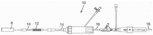
An introducer sheath may be used to safely introduce the delivery device into the vasculature (e.g., femoral artery) of a patient. The introducer sheath typically has an elongate sleeve that is inserted into the vasculature and a housing containing one or more sealing valves that allow the delivery device to be placed in fluid communication with the vasculature with minimal blood loss. Conventional introducer sheaths typically require a tubular loader to be inserted through a seal in the housing to provide an open path through the housing for a valve mounted on a balloon catheter. Conventional loaders extend from the proximal end of an introducer sheath, thus reducing the usable working length of a delivery device that can be inserted through the sheath and into the body.
Conventional methods of accessing a blood vessel (e.g., the femoral artery) prior to introduction of a delivery system include dilating the blood vessel using multiple dilators or sheaths of progressively increasing diameter. Such repeated insertions and vasodilations can increase the amount of time spent in the procedure, as well as the risk of damage to the blood vessel.
Radially expanded intravascular sheaths have been disclosed. Such sheaths tend to have complicated mechanisms, such as ratchet mechanisms that hold the shaft or sheath in the expanded configuration after introduction of a device having a diameter greater than the original diameter of the sheath.
However, delivering or removing prosthetic devices and other materials to or from a patient still poses significant risks to the patient. Furthermore, access to the vessel remains challenging because the relatively large profile of the delivery system can cause longitudinal and radial tearing of the vessel during insertion. The delivery system can also displace calcified plaque within the vessel, thereby also increasing the risk of clotting caused by the displaced plaque.
Accordingly, there remains a need in the art for an improved introducer sheath for use in intravascular systems for implantation of valves and other prosthetic devices.
Disclosure of Invention
Various aspects of current expandable sheaths may minimize trauma to the vessel by allowing the portion of the introducer sheath to temporarily expand to accommodate the delivery system and then return to the original diameter after passage of the delivery system. Some aspects may include sheaths having a smaller profile than prior art introducer sheaths. Furthermore, certain aspects may reduce the length of time the procedure takes, as well as reduce the risk of longitudinal or radial vessel tears or plaque dislodgement, as only one sheath is required, rather than several sheaths of different sizes. Unlike multiple insertions required to dilate a vessel, aspects of current expandable sheaths may require only a single vessel insertion.
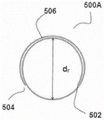
In one aspect, a sheath for introducing a prosthetic device comprising an inner liner (liner) and an outer layer is disclosed. At least a portion of the sheath may be designed or configured to locally expand from a first diameter (rest diameter) to a second diameter (expanded diameter) when the prosthetic device is pushed through the lumen of the sheath, and then to at least partially return to the first diameter upon passage of the prosthetic device.
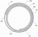
Also disclosed herein are aspects related to a sheath for delivering a medical device, wherein the sheath has a proximal end and a distal end and comprises: a variable diameter inner liner comprising a sheet having a first edge and a second edge and defined by an inner surface and an outer surface, wherein the sheet is wound in a coiled configuration such that at least a portion of the inner surface of the sheet overlaps at least a portion of the outer surface of the sheet, and wherein the first edge of the sheet is slidable along at least a portion of the inner surface of the sheet and the second edge is slidable along at least a portion of the outer surface of the sheet, wherein the inner surface of the sheet defines a circle having a longitudinal axisA cavity of the cylinder; an outer layer having an inner surface and an outer surface and extending around at least a portion of the variable diameter inner liner such that the inner surface of the outer layer is positioned adjacent to the outer surface of the inner liner, wherein the outer layer comprises: a braid or coil (coil); and a layer of an elastomeric polymer having a predetermined thickness and having an inner surface and an outer surface; wherein the inner liner of variable diameter is configured to be displaced from a predetermined rest diameter d by sliding a first edge of the sheet of material along at least a portion of the inner surface and sliding a second edge of the sheet of material along at least a portion of the outer surface during application of a radially outward force by passing the medical device through the lumen of the inner liner rExpand to an expanded diameter de。
Also disclosed herein is an aspect including a method of manufacturing a sheath having a proximal end and a distal end. In a certain aspect, a method of making such a sheath includes forming a variable diameter inner liner by rolling (rolling) a sheet of material, the sheet of material having a first edge and a second edge and wherein the sheet of material is defined by an inner surface and an outer surface in a rolled configuration such that at least a portion of the inner surface of the sheet of material overlaps at least a portion of the outer surface of the sheet of material forming an overlapping portion (overlapping portion), and wherein the first edge of the sheet of material is slidable along at least a portion of the inner surface of the sheet of material and the second edge is slidable along at least a portion of the outer surface of the sheet of material, wherein the inner surface of the sheet of material defines a cavity of a cylinder having a longitudinal axis; forming an outer layer having an inner surface and an outer surface and extending around at least a portion of the variable diameter inner liner such that the inner surface of the outer layer is positioned adjacent to the outer surface of the inner liner, wherein the outer layer comprises: a braid or coil; and a layer of an elastomeric polymer having a predetermined thickness and having an inner surface and an outer surface; wherein the inner liner of variable diameter is configured to be displaced from a predetermined rest diameter d by sliding a first edge of the sheet of material along at least a portion of the inner surface and sliding a second edge of the sheet of material along at least a portion of the outer surface during application of a radially outward force by passing the medical device through the lumen of the inner liner rExpand to an expanded diameter de。
Also disclosed are methods for delivering a medical deviceIn a further or alternative aspect of the sheath of (a), wherein the sheath has a proximal end and a distal end and comprises: a variable diameter inner liner comprising a sheet of material having a first edge and a second edge and defined by an inner surface and an outer surface, wherein the sheet of material is wound in a wound configuration such that at least a portion of the inner surface of the sheet of material overlaps at least a portion of the outer surface of the sheet of material, and wherein the first edge of the sheet of material is slidable along at least a portion of the inner surface of the sheet of material and the second edge is slidable along at least a portion of the outer surface of the sheet of material, wherein the inner surface of the sheet of material defines a cavity of a cylinder having a longitudinal axis; an outer layer having an inner surface and an outer surface and extending around at least a portion of the variable diameter inner liner such that the inner surface of the outer layer is positioned adjacent to the outer surface of the inner liner, wherein the outer layer comprises: at least one layer of a first elastomeric polymer having a predetermined thickness and having an inner surface and an outer surface; wherein the inner liner of variable diameter is configured to be displaced from a predetermined rest diameter d by sliding a first edge of the sheet of material along at least a portion of the inner surface and sliding a second edge of the sheet of material along at least a portion of the outer surface during application of a radially outward force by passing the medical device through the lumen of the inner liner rExpanded to an expanded diameter de。
Also disclosed are aspects related to a method of manufacturing a sheath having a proximal end and a distal end and comprising: forming a variable diameter inner liner by rolling a sheet of material, the sheet of material having a first edge and a second edge and wherein the sheet of material is defined by an inner surface and an outer surface in a rolled configuration such that at least a portion of the inner surface of the sheet of material overlaps at least a portion of the outer surface of the sheet of material forming an overlying portion, and wherein the first edge of the sheet of material is slidable along at least a portion of the inner surface of the sheet of material and the second edge is slidable along at least a portion of the outer surface of the sheet of material, wherein the inner surface of the sheet of material defines a cavity of a cylinder having a longitudinal axis; forming an outer layer having an inner surface and an outer surface and extending around at least a portion of the variable diameter inner liner such that the inner surface of the outer layer is positioned adjacent to the outer surface of the inner liner, wherein the outer layer comprises: at least one layer of a first elastomeric polymer having a predetermined thickness and having an inner surface and an outer surfaceA compound; wherein the inner liner of variable diameter is configured to be displaced from a predetermined rest diameter d by sliding a first edge of the sheet of material along at least a portion of the inner surface and sliding a second edge of the sheet of material along at least a portion of the outer surface during application of a radially outward force by passing the medical device through the lumen of the inner liner rExpand to an expanded diameter de。
Also disclosed herein are aspects related to a sheath for delivering a medical device, wherein the sheath has a proximal end and a distal end and comprises: a) an inner liner defining a lumen having a first resting diameter drAnd a second expanded diameter deWherein the lumen is configured to receive and pass a medical device therethrough, wherein the inner liner comprises a sheet comprising a first portion having a first surface and an opposing second surface, wherein a first end of the first portion is divided into a first segment having the first surface and the opposing second surface, and a third segment having the first surface and the opposing second surface, and wherein a second end of the first portion extends into the second segment having the first surface and the opposing second surface, wherein the sheet is rolled into a rolled configuration such that at least a portion of the first surface of the second segment overlaps at least a portion of the second surface of the first segment, wherein at least a portion of the first surface of the third segment overlaps at least a portion of the second surface of the second segment, and wherein at least a portion of the first surface of the third segment overlaps at least a portion of the second surface of the first segment, wherein the first surface of the first portion extends into the first surfaces of the first, second and third segments, and wherein the second surface of the first portion extends into the second surfaces of the second and third segments; wherein each segment is configured to slidably move along each other as the medical device passes through the lumen; wherein the sheet comprises a polymer layer; and b) an outer layer.
Also disclosed herein are aspects related to a sheath for delivering a medical device, wherein the sheath has a proximal end and a distal end and comprises: a variable diameter inner liner comprising a sheet having a first edge and a second edge and defined by an inner surface and an outer surface, wherein the sheet is wound in a wound configuration such that an inner portion of the sheetAt least a portion of the surface overlaps at least a portion of the outer surface of the sheet, and wherein a first edge of the sheet is slidable along at least a portion of the inner surface of the sheet and a second edge is slidable along at least a portion of the outer surface of the sheet, wherein the inner surface of the sheet defines a lumen of a sheath having a longitudinal axis; wherein the sheet comprises a polymer layer; an outer layer having a predetermined thickness and having an inner surface and an outer surface, and wherein the inner liner of variable diameter is configured to be displaced from the first rest diameter d by sliding a first edge of the sheet of material along at least a portion of the inner surface and a second edge of the sheet of material along at least a portion of the outer surface during application of a radially outward force by passing a medical device through a lumen of the inner linerrExpand to a second expanded diameter de。
In one aspect, disclosed herein is a sheath for delivering a medical device, wherein the sheath has a proximal end and a distal end and comprises: a variable diameter inner liner comprising a sheet comprising a polymer layer comprising a composite material (composite material), wherein the composite material comprises a polyolefin present in an amount of greater than 0 wt% to less than 100 wt% based on the total weight of the composite and a lubricious filler present in an amount of about 5 wt% to about 20 wt% of the total weight of the composite material, wherein the sheet is rolled into a rolled configuration such that at least a portion of an inner surface of the sheet overlaps at least a portion of an outer surface of the sheet, and wherein a first longitudinal edge of the sheet is slidable along at least a portion of the inner surface of the sheet and a second longitudinal edge is slidable along at least a portion of the outer surface of the sheet, wherein the inner surface of the sheet defines a lumen of a sheath having a longitudinal axis; and an outer layer having a predetermined thickness and having an inner surface and an outer surface, wherein the inner surface of the outer layer is disposed on the outer surface of the inner liner in a coiled configuration; and wherein the inner liner of variable diameter is configured to be displaced from the first rest diameter d by sliding the first edge of the sheet of material along at least a portion of the inner surface and the second edge of the sheet of material along at least a portion of the outer surface during application of a radially outward force by passing the medical device through the lumen of the inner liner rExpand to a second expanded diameter de。
In one aspect, disclosed herein is a sheath for delivering a medical device, wherein the sheath has a proximal end and a distal end, wherein the sheath comprises: a variable diameter inner liner comprising a sheet rolled into a rolled configuration such that at least a portion of an inner surface of the sheet overlaps at least a portion of an outer surface of the sheet, and wherein a first longitudinal edge of the sheet is slidable along at least a portion of the inner surface of the sheet and a second longitudinal edge is slidable along at least a portion of the outer surface of the sheet, wherein the inner surface of the sheet defines a lumen of a sheath having a longitudinal axis; and an outer layer having a predetermined thickness and having an inner surface and an outer surface, wherein the lubricious liner is disposed between the outer surface of the inner liner and the inner surface of the outer layer, and wherein the inner liner of variable diameter is configured to be displaced from the first resting diameter d by sliding a first edge of the sheet of material along at least a portion of the inner surface and sliding a second edge of the sheet of material along at least a portion of the outer surface during application of a radially outward force by passing the medical device through the lumen of the inner linerrExpand to a second expanded diameter d e。
In a still further aspect, a sheath for delivering a medical device is disclosed, wherein the sheath has a proximal end and a distal end and comprises: a variable diameter inner liner comprising a sheet rolled into a rolled configuration such that at least a portion of an inner surface of the sheet overlaps at least a portion of an outer surface of the sheet, and wherein a first longitudinal edge of the sheet is slidable along at least a portion of the inner surface of the sheet and a second longitudinal edge is slidable along at least a portion of the outer surface of the sheet, wherein the inner surface of the sheet defines a lumen of a sheath having a longitudinal axis; a tie layer (tie layer) disposed at an inner surface of the sheet such that when the sheet is in a rolled configuration, the tie layer is disposed between the overlapping portions and at least an innermost surface of the cavity; and/or a tie layer disposed at an outer surface of the sheet such that when the sheet is in a rolled configuration, the tie layer is disposed between the overlapping portions and at an outermost surface of the inner liner; at least one lubrication disposed on the tie layerA liner; and an outer layer having a predetermined thickness and having an inner surface and an outer surface, wherein the inner liner of variable diameter is configured to be displaced from the first rest diameter d by sliding a first edge of the sheet of material along at least a portion of the inner surface and sliding a second edge of the sheet of material along at least a portion of the outer surface during application of a radially outward force by passing the medical device through a lumen of the inner liner rExpand to a second expanded diameter de。
Also disclosed herein are aspects related to a sheath for delivering a medical device, wherein the sheath has a proximal end and a distal end and comprises: a variable diameter inner liner comprising a sheet rolled into a rolled configuration such that at least a portion of an inner surface of the sheet overlaps at least a portion of an outer surface of the sheet, and wherein a first longitudinal edge of the sheet is slidable along at least a portion of the inner surface of the sheet and a second longitudinal edge is slidable along at least a portion of the outer surface of the sheet, wherein the inner surface of the sheet defines a lumen of a sheath having a longitudinal axis; and an elongated tube forming an outer layer of the sheath, the elongated tube being positioned at least at the proximal end of the sheath and extending along at least a portion of the length of the sheath, having an inner surface and an outer surface, and wherein the elongated tube comprises: a) a first polymer layer, wherein the first polymer layer comprises a first composite composition comprising i) greater than 0 wt% to less than 100 wt%, based on the total weight of the first composite composition, of a polymer comprising a polyether block amide, a polyurethane, or a combination thereof; ii) less than about 65% inorganic filler based on the total weight of the first composite component; and iii) up to about 20% solid lubricant filler based on the total weight of the first composite component; and b) a second polymer layer comprising polyurethane; wherein the elongate tube is an impingement tube and is a coextrusion of the first and second polymers; wherein the inner liner of variable diameter is configured to be displaced from the first rest diameter d by sliding a first edge of the sheet of material along at least a portion of the inner surface and sliding a second edge of the sheet of material along at least a portion of the outer surface during application of a radially outward force by passing the medical device through the lumen of the inner liner rExpand to a second expanded diameter de。
In a still further aspect, a sheath for delivering a medical device is disclosed, wherein the sheath has a proximal end and a distal end and comprises: a variable diameter inner liner comprising a sheet rolled into a rolled configuration such that at least a portion of an inner surface of the sheet overlaps at least a portion of an outer surface of the sheet, and wherein a first longitudinal edge of the sheet is slidable along at least a portion of the inner surface of the sheet and a second longitudinal edge is slidable along at least a portion of the outer surface of the sheet, wherein the inner surface of the sheet defines a lumen of a sheath having a longitudinal axis; and an elongated tube forming an outer layer of the sheath, the elongated tube being positioned at least at the proximal end of the sheath and extending along at least a portion of the length of the sheath, having an inner surface and an outer surface, and wherein the elongated tube comprises: a) a first polymer layer, wherein the first polymer layer comprises a first composite component comprising i) greater than 0 wt% to less than 100 wt% of a polymer comprising a polyether block amide, a polyurethane, or a combination thereof, based on the total weight of the first composite component; ii) less than about 65% inorganic filler based on the total weight of the first composite component; and iii) up to about 20% solid lubricant filler based on the total weight of the first composite component; and b) a second polymer layer comprising polyurethane; wherein the second polymer layer at least partially overlaps the first polymer layer; and wherein the first polymer is disposed at the proximal end of the sheath and has a length shorter than the length of the second polymer layer; and wherein the inner liner of variable diameter is configured to be displaced from the first rest diameter d by sliding the first edge of the sheet of material along at least a portion of the inner surface and the second edge of the sheet of material along at least a portion of the outer surface during application of a radially outward force by passing the medical device through the lumen of the inner liner rExpand to a second expanded diameter de。
Also disclosed herein are aspects of a sheath for delivering a medical device, wherein the sheath has a proximal end and a distal end and comprises: a variable diameter inner liner comprising a sheet of material rolled into a rolled configuration such that at least a portion of an inner surface of the sheet of materialOverlapping at least a portion of the outer surface of the sheet, and wherein a first longitudinal edge of the sheet is slidable along at least a portion of the inner surface of the sheet and a second longitudinal edge is slidable along at least a portion of the outer surface of the sheet, wherein the inner surface of the sheet defines a lumen of a sheath having a longitudinal axis; and an outer layer having a predetermined thickness and having an inner surface and an outer surface, wherein at least a portion of an innermost surface of the outer layer is bonded to at least a portion of an outermost surface of the inner liner, and the variable diameter inner liner is configured to transition from the first resting diameter d by sliding a first edge of the sheet material along at least a portion of the inner surface and sliding a second edge of the sheet material along at least a portion of the outer surface during application of a radially outward force by passing the medical device through the lumen of the inner linerrExpand to a second expanded diameter de。
In some aspects, a sheath for delivering a medical device is disclosed, wherein the sheath has a proximal end and a distal end and comprises: a variable diameter inner liner comprising a sheet rolled into a rolled configuration such that at least a portion of an inner surface of the sheet overlaps at least a portion of an outer surface of the sheet, and wherein a first longitudinal edge of the sheet is slidable along at least a portion of the inner surface of the sheet and a second longitudinal edge is slidable along at least a portion of the outer surface of the sheet, wherein the inner surface of the sheet defines a lumen of a sheath having a longitudinal axis; and an outer layer having a predetermined thickness and having an inner surface and an outer surface; and a stiffening sleeve (reinforing socket) having a proximal end and a distal end and wherein the stiffening sleeve is disposed on at least a portion of the outer surface of the outer layer; wherein the reinforcing sleeve comprises an elastomer and a reinforcing element; and wherein the distal end of the reinforcing sleeve is bonded substantially seamlessly to at least a portion of the outer surface of the outer layer; wherein the inner liner of variable diameter is configured to be displaced from the first rest diameter d by sliding a first edge of the sheet of material along at least a portion of the inner surface and sliding a second edge of the sheet of material along at least a portion of the outer surface during application of a radially outward force by passing the medical device through the lumen of the inner liner rExpand to a second expanded diameter de。
In yet other aspects, a sheath for delivering a medical device is disclosed, wherein the sheath has a proximal end and a distal end and comprises: a variable diameter inner liner comprising a sheet rolled into a rolled configuration such that at least a portion of an inner surface of the sheet overlaps at least a portion of an outer surface of the sheet, and wherein a first longitudinal edge of the sheet is slidable along at least a portion of the inner surface of the sheet and a second longitudinal edge is slidable along at least a portion of the outer surface of the sheet, wherein the inner surface of the sheet defines a lumen of a sheath having a longitudinal axis; and an outer layer having a predetermined thickness and having an inner surface and an outer surface and extending from a proximal end of the sheath to a distal end of the sheath; and an inflatable shield (balloon guard) having a proximal end and a distal end and disposed over at least a portion of the outer layer, and wherein the inflatable shield is configured to remain outside of the subject's blood vessel and maintain hemostasis; wherein the proximal end of the inflatable shield is connected to the proximal most portion of the outer layer and/or a hub (hub) of the sheath, wherein the distal end of the inflatable shield radially surrounds at least a portion of the outer layer, and wherein the distal end is not bonded to the outer layer; and wherein the inflatable shield is configured to adjust a length of the shield according to a depth of insertion of the inner and outer layers of the sheath into the blood vessel of the subject.
Further disclosed are aspects related to a method of manufacturing a sheath having a proximal end and a distal end and comprising: a) forming an inner liner by: i) providing a dual lumen tubing comprising two passageways extruded in a single tube configuration; wherein the dual cavities comprise at least one polymer layer; wherein the first channel has an inner surface and an outer surface; wherein the second channel has an inner surface and an outer surface; wherein the second channel is positioned within the first channel such that at least a portion of a circumference of the first channel and at least a portion of a circumference of the second channel have at least one shared inner surface and at least one shared outer surface; and wherein the outer surface of the first passageway defines the outer surface of the dual lumen tubing; ii) cutting the first channel longitudinally at a portion of the circumference of the first channel not shared with the circumference of the second channel to form a first sheet having a first edge and a second edge, and the second channel is arranged longitudinally along at least a portion of the first sheet(ii) a Such that at least part of the circumference of the second channel has at least such a portion: having a surface shared with the first sheet along the length of the sheet and along the length of the second channel; iii) cutting the second channel longitudinally at a portion of the circumference of the second channel adjacent to the surface shared with the first sheet to form a second sheet having a first edge and a second edge, wherein the second edge is defined by the portion of the surface shared with the first sheet; iv) rolling the first and second sheets into a rolled configuration such that: I) the shared surface between the second and first sheets forming a first portion of the inner liner having a first surface and an opposing second surface; II) at least part of the second sheet forms a first section of the inner liner having a first surface and an opposing second surface; III) wherein a portion of the first sheet adjacent to and extending to the second end of the second sheet forms a second section of the inner liner having a first surface and an opposing second surface; and IV) wherein a portion of the first sheet adjacent to and extending to the second end of the second sheet forms a third section of the inner liner having a first surface and an opposing second surface; wherein in the rolled configuration, at least a portion of the first surface of the second segment overlaps at least a portion of the second surface of the first segment, wherein at least a portion of the first surface of the third segment overlaps at least a portion of the second surface of the second segment, and wherein at least a portion of the first surface of the third segment overlaps at least a portion of the second surface of the first segment; wherein the first surface of the first portion extends into the first surfaces of the first, second and third segments, and wherein the second surface of the first portion extends into the second surfaces of the second and third segments, and b) arranging the outer layer to form a sheath; wherein the formed sheath is configured to be slidably moved from the first resting diameter d by each segment along each other rTo a second expanded diameter deAnd returns to the first resting diameter d after passage of the medical devicerSubstantially the same diameter.
Also disclosed herein is a method of manufacturing a sheath having a proximal end and a distal end and comprising: a) forming a variable diameter inner liner by: i) lifting deviceProviding an elongated single lumen tubing comprising at least one polymer layer; ii) cutting longitudinally at least part of the circumference of the elongated single lumen tubing to form a sheet having a first longitudinal edge and an opposing second longitudinal edge and having an inner surface and an outer surface; iii) forming the variable diameter inner liner by: rolling the sheet in a rolled configuration such that at least a portion of an inner surface of the sheet overlaps at least a portion of an outer surface of the sheet, thereby forming an overlapping portion, and wherein a first edge of the sheet is slidable along at least a portion of the inner surface of the sheet and a second edge is slidable along at least a portion of the outer surface of the sheet, wherein the inner surface of the sheet defines a lumen of a sheath having a longitudinal axis; and b) disposing the outer layer over at least a portion of the outer layer of the inner liner to form a sheet configured to be displaced from a predetermined rest diameter d by sliding the first longitudinal edge of the sheet along at least a portion of the inner surface and the second longitudinal edge of the sheet along at least a portion of the outer surface during application of a radially outward force by passing the medical device through the lumen of the inner liner rExpand to an expanded diameter deThe sheath of (3).
In some aspects, methods of forming a sheath are disclosed, comprising: a) positioning an elongated tubular on a mandrel; b) disposing a quantity of lubricant on an outer surface of an elongated tubular in a predetermined pattern; c) solidifying the lubricant; d) cutting the elongated tube at a portion of a circumference of the tube along a length of the tube to form a sheet having an outer surface and an inner surface and a first longitudinal edge and a second longitudinal edge; wherein the inner surface forms a sheath lumen and at least a portion of the outer surface comprises a lubricant arranged in a predetermined pattern; e) rolling the sheet into a rolled configuration such that at least a portion of the inner surface of the sheet overlaps at least a portion of the outer surface of the sheet, thereby forming an overlapping portion, and wherein the first edge of the sheet is slidable along at least a portion of the inner surface of the sheet and the second edge is slidable along at least a portion of the outer surface of the sheet; f) disposing an outer layer having an inner surface and an outer surface on the outer surface of the inner liner such that a lubricant is disposed between at least a portion of the inner surface of the outer layer and at least a portion of the outer surface of the inner layer to form a sheath; wherein the sheath is configured to pass medical treatment During the application of a radially outward force of the device through the lumen of the inner liner, the device is moved from the predetermined resting diameter d by sliding the first longitudinal edge of the sheet along at least part of the inner surface and the second longitudinal edge of the sheet along at least part of the outer surfacerExpanded to an expanded diameter de。
While in other aspects, methods of manufacturing a sheath having a proximal end and a distal end and comprising: a) extruding a tubular body to form an elongate pipe comprising a composite material, wherein the composite material comprises a polyolefin present in an amount of greater than 0 wt% to less than 100 wt% based on the total weight of the composite and a lubricating filler present in an amount of about 5 wt% to about 20 wt% of the total weight of the composite; b) cutting the elongated tube at least a portion of the circumference along the length of the elongated tube to form a sheet; c) forming an inner liner by: rolling the sheet into a rolled configuration such that at least a portion of an inner surface of the sheet overlaps at least a portion of an outer surface of the sheet and wherein a first longitudinal edge of the sheet is slidable along at least a portion of the inner surface of the sheet and a second longitudinal edge is slidable along at least a portion of the outer surface of the sheet, wherein the inner surface of the sheet defines a lumen of a sheath having a longitudinal axis; and d) positioning an outer layer having a predetermined thickness and having an inner surface and an outer surface, wherein the inner surface of the outer layer is disposed on the outer surface of the inner liner in a coiled configuration; and wherein the inner liner of variable diameter is configured to be displaced from the first rest diameter d by sliding the first edge of the sheet of material along at least a portion of the inner surface and the second edge of the sheet of material along at least a portion of the outer surface during application of a radially outward force by passing the medical device through the lumen of the inner liner rExpand to a second expanded diameter de。
In a still further aspect, a method of manufacturing a sheath having a proximal end and a distal end and comprising: a) coextruding a polymer layer and a tie layer to form an elongated tube; b) positioning at least one lubricious liner at an outer surface of the inner liner; c) cutting the elongated tube at least a portion of the circumference along the length of the elongated tube to form a sheet; d) forming an inner liner by: the sheet material is rolled into a rolled configuration,causing at least a portion of an inner surface of the sheet to overlap at least a portion of an outer surface of the sheet and wherein a first longitudinal edge of the sheet is slidable along at least a portion of the inner surface of the sheet and a second longitudinal edge is slidable along at least a portion of the outer surface of the sheet, wherein the inner surface of the sheet defines a lumen of a sheath having a longitudinal axis; and e) positioning an outer layer having a predetermined thickness and having an inner surface and an outer surface over the at least one lubricious liner to form a sheath; wherein the inner liner of variable diameter is configured to be displaced from the first rest diameter d by sliding a first edge of the sheet of material along at least a portion of the inner surface and sliding a second edge of the sheet of material along at least a portion of the outer surface during application of a radially outward force by passing the medical device through the lumen of the inner liner rExpand to a second expanded diameter de。
In a still further aspect, a method of manufacturing a sheath having a proximal end and a distal end and comprising: a) coextruding a polymer layer and a tie layer to form an elongated tube; b) positioning at least one lubricious liner on the tie layer; c) cutting the elongated tube at least a portion of the circumference along the length of the elongated tube to form a sheet; d) forming an inner liner by: rolling the sheet into a rolled configuration such that at least a portion of an inner surface of the sheet overlaps at least a portion of an outer surface of the sheet and wherein a first longitudinal edge of the sheet is slidable along at least a portion of the inner surface of the sheet and a second longitudinal edge is slidable along at least a portion of the outer surface of the sheet, wherein the inner surface of the sheet defines a lumen of a sheath having a longitudinal axis; such that when the sheet is in the rolled configuration, the tie layer is disposed between the overlapping portions and at least at the inner surface of the cavity; and/or such that when the sheet is in a rolled configuration, the tie layer is disposed between the overlapping portions and at the outermost surface of the inner liner; e) positioning an outer layer having a predetermined thickness and having an inner surface and an outer surface to form a sheath; wherein the inner liner of variable diameter is configured to be displaced from the first resting diameter by sliding a first edge of the sheet of material along at least a portion of the inner surface and sliding a second edge of the sheet of material along at least a portion of the outer surface during application of the radial force drExpand to a second expanded diameter de。
Additionally or alternatively, a method of manufacturing a sheath having a proximal end and a distal end and comprising: a) coextruding an elongated impingement tube comprising a first polymer layer and a second polymer layer; wherein i) the first polymer layer comprises: a first composite component comprising greater than 0% to less than 100% of a polymer comprising a polyether block amide, a polyurethane, or a combination thereof, based on the total weight of the first composite component; less than about 65% inorganic filler based on the total weight of the first composite component; and up to about 20% solid lubricant filler, based on the total weight of the first composite component; ii) the second polymer layer comprises polyurethane; wherein the first polymer layer defines an inner surface of the tubing and the second polymer layer defines an outer surface of the tubing; b) forming an inner liner by: rolling the sheet into a rolled configuration such that at least a portion of an inner surface of the sheet overlaps at least a portion of an outer surface of the sheet and wherein a first longitudinal edge of the sheet is slidable along at least a portion of the inner surface of the sheet and a second longitudinal edge is slidable along at least a portion of the outer surface of the sheet, wherein the inner surface of the sheet defines a lumen of a sheath having a longitudinal axis; and c) disposing an elongated impingement tube on the sheath such that the elongated impingement tube forms an outer layer of the sheath, and wherein the elongated tube is positioned at least at a proximal end of the sheath and extends along at least a portion of a length of the sheath, wherein the elongated impingement tube is configured to pass from an initial diameter d in an unexpanded position as the medical device passes therethrough oReversibly expandable to an expanded diameter d in an expanded positione(ii) a And wherein the inner liner of variable diameter is configured to be displaced from the first rest diameter d by sliding a first edge of the sheet material along at least part of the inner surface and a second edge of the sheet material along at least part of the outer surface during application of the radial forcerExpand to a second expanded diameter de。
Also disclosed is a method of manufacturing a sheath having a proximal end and a distal end and comprising: a) forming an inner liner by: rolling the sheet into a rolled configuration such that at least an inner surface of the sheet is in a rolled configurationPartially overlapping at least a portion of the outer surface of the sheet and wherein a first longitudinal edge of the sheet is slidable along at least a portion of the inner surface of the sheet and a second longitudinal edge is slidable along at least a portion of the outer surface of the sheet, wherein the inner surface of the sheet defines a lumen of a sheath having a longitudinal axis; b) disposing a first polymer layer comprising a first composite component, the first composite component comprising greater than 0% to less than 100% of a polymer based on the total weight of the first composite component, the polymer comprising a polyether block amide, a polyurethane, or a combination thereof; less than about 65% inorganic filler based on the total weight of the first composite component; and up to about 20% solid lubricant filler, based on the total weight of the first composite component; wherein the first polymer layer is disposed on the proximal portion of the inner liner and has a length of about 5cm to about 15 cm; c) disposing a second polymer layer comprising polyurethane on the first polymer layer, wherein the second polymer layer extends along the length of the sheath; wherein the first polymer layer and the second polymer layer together form an outer layer of the sheath, the outer layer configured to be displaced from an initial diameter d in an unexpanded position as the medical device is passed therethrough oReversibly expandable to an expanded diameter d in an expanded positione(ii) a And wherein the inner liner of variable diameter is configured to be displaced from the first rest diameter d by sliding a first edge of the sheet material along at least part of the inner surface and a second edge of the sheet material along at least part of the outer surface during application of the radial forcerExpand to a second expanded diameter de。
Alternatively or additionally, a method of manufacturing a sheath having a proximal end and a distal end and comprising: a) forming an inner liner by: rolling the sheet into a rolled configuration such that at least a portion of an inner surface of the sheet overlaps at least a portion of an outer surface of the sheet and wherein a first longitudinal edge of the sheet is slidable along at least a portion of the inner surface of the sheet and a second longitudinal edge is slidable along at least a portion of the outer surface of the sheet, wherein the inner surface of the sheet defines a lumen of a sheath having a longitudinal axis; b) disposing an outer layer over the inner liner to form a sheath; c) positioning a sheath over a mandrel configured to rotate; d) aligning the mandrel with the laser beam, laserThe light beam is configured to move to a predetermined distance along a longitudinal axis of the sheath under conditions effective to form a bond; e) forming a bond at a predetermined portion of the sheath between at least a portion of an outermost surface of the inner liner and at least a portion of an innermost surface of the outer layer, wherein the predetermined portion is substantially free of a lubricant and/or a tie layer; and wherein the inner liner of variable diameter is configured to be displaced from the first rest diameter d by sliding a first edge of the sheet material along at least part of the inner surface and a second edge of the sheet material along at least part of the outer surface during application of the radial force rExpand to a second expanded diameter de。
Alternatively or additionally, a method of manufacturing a sheath having a proximal end and a distal end and comprising: a) forming an inner liner by: rolling the sheet into a rolled configuration such that at least a portion of an inner surface of the sheet overlaps at least a portion of an outer surface of the sheet and wherein a first longitudinal edge of the sheet is slidable along at least a portion of the inner surface of the sheet and a second longitudinal edge is slidable along at least a portion of the outer surface of the sheet, wherein the inner surface of the sheet defines a lumen of a sheath having a longitudinal axis; and b) disposing an outer layer over the inner liner to form a sheath; c) positioning a sheath over a mandrel configured to rotate; d) inserting the mandrel into a radial compression head bonder, the radial compression head bonder including a collapsible aperture configured to compress the sheath to a predetermined diameter, and wherein the radial compression head bonder includes a plurality of dies, wherein at least one of the plurality of dies is heated to form a bond at a terminal front portion (predetermined port) of the sheath; e) forming a bond at a predetermined portion of the sheath between at least a portion of an outermost surface of the inner liner and at least a portion of an innermost surface of the outer layer, wherein the predetermined portion is substantially free of a lubricant and/or a tie layer; and wherein the inner liner of variable diameter is configured to be displaced from the first rest diameter d by sliding a first edge of the sheet material along at least part of the inner surface and a second edge of the sheet material along at least part of the outer surface during application of the radial force rExpand to a second expanded diameter de。
Additionally or in the alternative, a method of manufacturing a sheath having a proximal end and a distal end and comprising: a) forming an inner liner by: rolling the sheet into a rolled configuration such that at least a portion of an inner surface of the sheet overlaps at least a portion of an outer surface of the sheet and wherein a first longitudinal edge of the sheet is slidable along at least a portion of the inner surface of the sheet and a second longitudinal edge is slidable along at least a portion of the outer surface of the sheet, wherein the inner surface of the sheet defines a lumen of a sheath having a longitudinal axis; and b) disposing an outer layer over at least a portion of the inner liner to form a sheath; c) disposing a reinforcing sleeve having a proximal end and a distal end over at least a portion of the outer layer; wherein the reinforcing sleeve comprises an elastomer and a reinforcing element; and d) bonding the distal end of the reinforcing sleeve to at least a portion of the outer layer substantially seamlessly, wherein the inner liner of variable diameter is configured to be displaced from the first resting diameter d by sliding the first edge of the sheet material along at least a portion of the inner surface and the second edge of the sheet material along at least a portion of the outer surface during application of the radial forcerExpand to a second expanded diameter d e。
Additionally or in the alternative, a method of manufacturing a medical device having a proximal end and a distal end and comprising: a) forming an inner liner by: rolling the sheet into a rolled configuration such that at least a portion of an inner surface of the sheet overlaps at least a portion of an outer surface of the sheet and wherein a first longitudinal edge of the sheet is slidable along at least a portion of the inner surface of the sheet and a second longitudinal edge is slidable along at least a portion of the outer surface of the sheet, wherein the inner surface of the sheet defines a lumen of a sheath having a longitudinal axis; b) disposing an outer layer over at least a portion of the inner liner to form a sheath; c) disposing an inflatable shield having a proximal end and a distal end over at least a portion of the outer layer, wherein the inflatable shield is configured to remain outside of the subject's blood vessel and maintain hemostasis; d) connecting a proximal end of the inflation shield to a proximal-most portion of the outer layer and/or a lining of the sheath, wherein a distal end of the inflation shield radially surrounds at least a portion of the outer layer and wherein the distal end is not bonded to the outer layer; and wherein the inflation guard is configured to conform to the lining of the sheathThe depth of insertion of the inner and outer layers into the subject's blood vessel to adjust the length of the shield; wherein the inner liner of variable diameter is configured to be displaced from the first rest diameter d by sliding a first edge of the sheet material along at least part of the inner surface and a second edge of the sheet material along at least part of the outer surface during application of the radial force rExpand to a second expanded diameter de。
The foregoing and other features and advantages of the present disclosure will become more apparent from the following detailed description, which proceeds with reference to the accompanying figures.
Drawings
Fig. 1 is an elevation view of a sheath according to the present disclosure in conjunction with an intravascular delivery device for implanting a prosthetic valve.
Fig. 2A and 2B are cross-sectional views of aspects of a sheath for introducing a prosthetic device into a patient, and fig. 2C is a perspective view of one component of such a sheath.
Fig. 3A, 3B, and 3C are elevation views of three aspects of a sheath according to the present disclosure, with uniform and varying rest drDiameter.
Fig. 4A-4D illustrate partial elevation views of various exemplary aspects of a woven structure having various PICs according to the present disclosure.
Fig. 5A and 5B illustrate cross-sectional views of an aspect of an exemplary inner liner: fig. 5A depicts an unexpanded configuration, while fig. 5B depicts an expanded configuration.
Fig. 6A-6E and 6H show cross-sectional views of various aspects of an exemplary sheath. Fig. 6F, 6G, and 6I show perspective views of various aspects of an exemplary sheath.
Fig. 7 illustrates a block diagram of one aspect of a method of manufacturing a sheath according to the present disclosure.
Fig. 8 illustrates a block diagram of another aspect of a method of manufacturing a sheath according to the present disclosure.
Fig. 9A-9K illustrate cross-sectional or side views of various method steps of the method shown in fig. 7-8.
Fig. 10 is an elevation view of an expandable sheath and a representative housing according to the present disclosure.
Fig. 11 is an enlarged cross-sectional view of the distal end of the sheath of fig. 10.
Fig. 12A-12D are cross-sectional views of the distal end of the exemplary sheath of fig. 14, taken along line 37-37 in fig. 11; fig. 12A shows a cross-sectional view of an exemplary sheath with lubricant disposed between the sliding portion and the overlapping portion of the sheet and with the braid or coil not embedded in the elastomeric polymer layer; fig. 12B shows a cross-sectional view of an exemplary sheath with lubricant disposed between the sliding portion and the overlapping portion of the sheet and lubricant disposed between the inner liner and the outer layer, wherein the braid or coil is not embedded in the layer of elastomeric polymer; FIG. 12C shows a cross-sectional view of an exemplary sheath with lubricant disposed between the inner liner and the outer layer, wherein the braid or coil is not embedded in the elastomeric polymer layer; in the presence and absence of a lubricant; fig. 12D shows a cross-sectional view of an exemplary sheath with a lubricant disposed between the sliding portion and the overlapping portion of the sheet and a lubricant disposed between the inner liner and the outer layer, wherein the braid or coil is at least partially embedded in the elastomeric polymer layer.
Fig. 13 is a cross-sectional view of the proximal section of the sheath of fig. 10 taken along line 38-38 in fig. 11; fig. 13A shows a cross-sectional view of an exemplary sheath with lubricant disposed between the sliding portion and the overlapping portion of the sheet and with the braid or coil not embedded in the elastomeric polymer layer; FIG. 13B shows a cross-sectional view of an exemplary sheath with lubricant disposed between the sliding portion and the overlapping portion of the sheet and lubricant disposed between the inner liner and the outer layer, wherein the braid or coil is not embedded in the elastomeric polymer layer; FIG. 13C shows a cross-sectional view of an exemplary sheath with a mesolubricant disposed between the inner liner and the outer layer, wherein the braid or coil is not embedded in the elastomeric polymer layer; in the presence and absence of a lubricant; fig. 13D shows a cross-sectional view of an exemplary sheath with a lubricant disposed between the sliding portion and the overlapping portion of the sheet and a lubricant disposed between the inner liner and the outer layer, wherein the braid or coil is at least partially embedded in the elastomeric polymer layer.
Fig. 14 is a cross-sectional view of the sheath of fig. 35 in a resting (unexpanded) configuration, taken along line 39-39 in fig. 11.
Fig. 15 shows a cross-sectional view of the sheath of fig. 14 in an expanded configuration.
Fig. 16 shows experimental data for an exemplary sheath in one aspect.
Fig. 17 shows experimental data for an exemplary sheath in another aspect.
Fig. 18 depicts the inner liner of an exemplary sheath in a collapsed and unexpanded configuration in one aspect.
FIG. 19 depicts a cross-sectional view of an exemplary sheath in one aspect, showing the inner liner and outer layer as shown in FIG. 18.
20A-20C depict exemplary fabrication steps for the inner liner shown in FIG. 18.
Fig. 21A-21B depict an exemplary sheath in one aspect, showing the inner and outer layers in a collapsed and unexpanded configuration: fig. 21A illustrates a cross-sectional schematic view of the sheath, while fig. 21B depicts a side-view schematic view of the sheath.
Fig. 22A-22B depict an exemplary sheath in one aspect: FIG. 22A shows a schematic diagram of a cross-sectional view of a sheath in a collapsed configuration (left) and an expanded configuration (right); fig. 22B shows a snapshot of an exemplary sheath expanded during passage of a medical device.
Fig. 23 depicts a cross-sectional pictorial representation of an exemplary sheath in one aspect.
Fig. 24A-24B depict cross-sectional pictorial representations of an exemplary sheath in one aspect.
Fig. 25A-25H depict various inner liner combinations for an exemplary sheath: FIGS. 25A-25D illustrate cross-sectional views of various liners prior to formation of an exemplary inner liner; fig. 25E-25H show various cross-sectional views of an exemplary inner liner in a rolled configuration.
FIG. 26 depicts a side view of an exemplary lubricant pattern disposed on an exemplary inner liner in one aspect.
Fig. 27 depicts a cross-sectional view of an exemplary sheath in a collapsed and expanded configuration, with a bond between the inner and outer liners.
Fig. 28A-28C depict various methods of forming a bond between the inner and outer layers of an exemplary sheath.
Fig. 29A-29F depict schematic views of the stiffening cuff effect (fig. 25A-25D) and the inflatable shield effect (fig. 25A-25B and 25E-25F) on the patient's anatomy.
Fig. 30A-30B depict schematic views of a reinforcing sleeve present in an exemplary sheath in one aspect.
Detailed Description
The present disclosure may be understood more readily by reference to the following detailed description, examples, drawings, and claims, and their previous and following description. However, before the present articles, systems, and/or methods are disclosed and described, it is to be understood that this disclosure is not limited to the specific or exemplary aspects of the articles, systems, and/or methods disclosed unless otherwise specified, as such may, of course, vary. It is also to be understood that the terminology used herein is for the purpose of describing particular aspects only and is not intended to be limiting.
The following description of the present disclosure is provided as an enabling teaching of the present disclosure in its best, currently known aspect. To this end, those skilled in the relevant art will recognize and appreciate that many changes can be made to the various aspects of the disclosure described herein, while still obtaining the beneficial results of the present disclosure. It will also be apparent that some of the desired benefits of the present disclosure can be obtained by selecting some of the features of the present disclosure without utilizing other features. Accordingly, one of ordinary skill in the relevant art will recognize that numerous modifications and adaptations to the present disclosure are possible and can even be desirable in certain circumstances and are a part of the present disclosure. The following description is, therefore, again provided as an example of the principles of the present disclosure and not in limitation thereof.
Definition of
As used in this application and the claims, the singular forms "a", "an" and "the" include the plural forms unless the context clearly dictates otherwise. Thus, for example, reference to "a polymer" includes aspects having two or more such polymers, unless the context clearly dictates otherwise.
It is also to be understood that the terminology used herein is for the purpose of describing particular aspects only and is not intended to be limiting. As used in the specification and claims, the term "comprising" may include aspects "consisting of … …" and "consisting essentially of … …". Furthermore, the term "comprising" means "including".
For the terms "for example" and "such as," and grammatical equivalents thereof, the phrase "without limitation" should be read as followed unless otherwise expressly stated.
Reference in the specification and concluding claims to parts by weight of a particular element or component in a composition or article, means the weight relationship between the element or component and any other element or component in the composition or article for which parts by weight are indicated. Thus, in a selected part of the composition or composition containing 2 parts by weight of component X and 5 parts by weight of component Y, X and Y are present in a ratio of 2: 5, regardless of whether additional components are present in the composition.
Unless specifically stated to the contrary, the weight percentages of a component are based on the total weight of the formulation or composition in which the component is included.
Ranges may be expressed herein as from "about" one particular value, and/or to "about" another particular value. When such a range is expressed, another aspect includes from the one particular value and/or to the other particular value. Similarly, when values are expressed as approximations, by use of the antecedent "about," it will be understood that the particular value forms another aspect. It will be further understood that the endpoints of each of the ranges are significant both in relation to the other endpoint, and independently of the other endpoint.
As used herein, the term "substantially" when used in reference to a composition means at least about 80%, at least about 85%, at least about 90%, at least about 91%, at least about 92%, at least about 93%, at least about 94%, at least about 95%, at least about 96%, at least about 97%, at least about 98%, at least about 99%, or about 100% by weight, based on the total weight of the composition, the particular feature, or component.
As used herein, the term "substantially" in the context of, for example, "substantially free of" refers to a composition that: having less than about 1 wt%, such as less than about 0.5 wt%, less than about 0.1 wt%, less than about 0.05 wt%, or less than about 0.01 wt% of the recited material, based on the total weight of the composition.
As used herein, the term "substantially identical reference composition" or "substantially identical reference article" refers to a reference composition or article that comprises substantially identical components in the absence of inventive components. In another exemplary aspect, the term "substantially" in the context of, for example, "substantially identical reference compositions" refers to reference compositions comprising substantially identical components and wherein the inventive components are replaced by components common in the art.
Furthermore, the terms "coupled" and "associated" generally mean electrically, electromagnetically, and/or physically (e.g., mechanically or chemically) coupled or connected, and do not exclude the presence of intermediate elements between coupled or associated items.
As used herein, the term "atraumatic" is well known in the art and refers to devices or procedures that minimize tissue damage.
As used herein, the term or phrase "effective", "effective amount" or "effective … strap element" refers to an amount or strap element capable of performing a function or property for which the effective amount or strap element is expressed. As will be noted below, the exact amount or particular strip member required will vary from aspect to aspect depending upon recognized variables such as the materials employed and the processing strip members observed. Thus, it is not always possible to specify an exact "effective amount" or "effective … strap member". However, suitable effective amounts will be readily determined by one of ordinary skill in the art using only routine experimentation.
Although the operations of the exemplary aspects of the disclosed methods may be described in a particular sequential order for convenience of presentation, it should be understood that the disclosed aspects may encompass orders of operations that differ from the particular sequential order disclosed. For example, in some cases, operations described sequentially may be rearranged or performed concurrently. Furthermore, the description and disclosure provided in connection with a particular aspect is not limited to that aspect and may apply to any aspect disclosed.
Moreover, for the sake of brevity, the attached figures may not show the various ways in which the disclosed systems, methods, and apparatus can be used in combination with other systems, methods, and apparatus (which are readily discernible by one of ordinary skill in the art based on the present disclosure). Additionally, the description sometimes uses terms such as "produce" and "provide" to describe the disclosed methods. These terms are high-level abstract representations of the actual operations that may be performed. The actual operations that correspond to these terms may vary depending on the particular embodiment, and can be readily discerned by one of ordinary skill in the art based on the present disclosure.
Sheath tube
Disclosed herein is one aspect of a sheath for delivering a medical device, wherein the sheath has a proximal end and a distal end and comprises: a) an inner liner defining a cavity having a first resting diameter drAnd a second expanded diameter deWherein the lumen is configured to receive and pass a medical device therethrough, wherein the inner liner comprises a sheet comprising a first portion having a first surface and an opposing second surface, wherein a first end of the first portion is divided into a first segment having the first surface and the opposing second surface, and a third segment having the first surface and the opposing second surface, and wherein a second end of the first portion extends into the second segment having the first surface and the opposing second surface, wherein the sheet is rolled into a rolled configuration such that at least a portion of the first surface of the second segment overlaps at least a portion of the second surface of the first segment, wherein at least a portion of the first surface of the third segment overlaps at least a portion of the second surface of the second segment, and wherein at least a portion of the first surface of the third segment overlaps at least a portion of the second surface of the first segment, wherein the first surface of the first part extends to the first section A first surface of the segment, the second segment, and the third segment, and wherein a second surface of the first portion extends into a second surface of the second and third segments; wherein each segment is configured to slidably move along each other as the medical device passes through the lumen; wherein the sheet comprises a polymer layer; and an outer layer.
In certain aspects, the resting diameter drMay be substantially uniform along the longitudinal axis of the lumen. In yet other aspects, the resting diameter drVaries along the longitudinal axis of the lumen, and wherein the diameter of rest d at the proximal endrGreater than the resting diameter d at the distal endr. In one disclosed aspect, the expanded diameter deConfigured to accommodate a medical device passing through a lumen. In yet another aspect, the sheath is retractable to a predetermined resting diameter d after the medical device has been passed through the lumenr。
In one disclosed aspect, the sheet of the sheath comprises high density polyethylene, polypropylene, polyamide, fluoropolymer, copolymers thereof, or blends thereof. In still further aspects, the sheet can have a multilayer structure. In a still further aspect, the inner surface of the sheet is at least partially ribbed.
In one exemplary aspect, the sheet is lubricious and has a coefficient of friction of less than about 0.5.
In a still further aspect, an amount of the first lubricant is disposed between at least a portion of the inner liner and at least a portion of the outer layer. In still other disclosed aspects, an amount of the second lubricant may be disposed between at least a portion of the overlapping portion of the sheets and at least a portion of the sliding portion of the sheets.
In still other disclosed aspects, the outer surface of the layer of elastomeric polymer may define at least a portion of the outer surface of the outer layer. In some of the disclosed aspects, at least a portion of the inner surface of the layer of elastomeric polymer is at least partially bonded to at least a portion of the outer surface of the sheet of inner liner. In a still further aspect, at least a portion of the inner surface of the layer of elastomeric polymer can define at least a portion of the inner surface of the outer layer. While in other aspects, at least a portion of the braid or coil can define at least a portion of the inner surface of the outer layer.
In one disclosed aspect, the sheath may further include a first strip of elastomeric polymer disposed between at least a portion of the outer surface of the sheet that does not include the overlapping portion of the sheet and the inner surface of the outer layer along at least a portion of the longitudinal axis of the lumen. In other aspects, the sheath can further include a second strip of an elastomeric polymer disposed between at least a portion of an outer surface of the sheet at the proximal end of the sheath and an inner surface of the outer layer. In yet other aspects, the sheath can further include a third strip of elastomeric polymer disposed between at least a portion of the outer surface of the sheet at the distal end of the sheath and the inner surface of the outer layer.
In a still further aspect, the braid or coil is an expandable braid or coil. In yet a further aspect, the braid or coil can comprise at least one filament comprising stainless steel, nitinol, a polymeric material, or a composite material. In certain aspects, the at least one filament may be a round filament or a flat filament. In aspects in which the at least one filament comprises a polymeric material, the polymeric material may be polyester or nylon. In aspects in which the at least one filament is round, the round filament may have a diameter of less than about 0.015 ". And in aspects where the at least one filament is flat, the flat filament may have a height of less than about 0.006 "and a width of greater than about 0.003" to about 0.015 ". In yet a further aspect, the braid may have a crossover (PIC) count per inch of less than 50. In still further aspects, the PIC of the braid may vary along the longitudinal axis of the lumen.
In a still further aspect, where the at least one filament is nitinol, the nitinol is in deAnd (5) performing heat setting. In yet other aspects, where the at least one filament comprises stainless steel or nitinol, the filament may be configured to be atraumatic at least at the distal end of the sheath.
In still other aspects, the elastomeric polymer present in the outer layer comprises a styrenic based elastomer, a polyurethane, a latex, a copolymer thereof, a blend thereof, or a coextrusion thereof. In one aspect, the elastomeric polymer exhibits a shore a hardness of less than 90. In certain aspects, the braid or coil can be at least partially embedded within at least a portion of the layer of elastomeric polymer. However, in other aspects, the hydrophilic coating can be disposed on an outer surface of the outer layer.
Also disclosed herein is an aspect, including a method of manufacturing a sheath having a proximal end and a distal end. In a certain aspect, a method of manufacturing such a sheath comprises: forming a variable diameter inner liner by rolling a sheet, the sheet having a first edge and a second edge and wherein the sheet is defined by an inner surface and an outer surface in a rolled configuration such that at least a portion of the inner surface of the sheet overlaps at least a portion of the outer surface of the sheet forming an overlapping portion, and wherein the first edge of the sheet is slidable along at least a portion of the inner surface of the sheet and the second edge is slidable along at least a portion of the outer surface of the sheet, wherein the inner surface of the sheet defines a lumen of a sheath having a longitudinal axis; forming an outer layer having an inner surface and an outer surface and extending around at least a portion of the variable diameter inner liner such that the inner surface of the outer layer is positioned adjacent to the outer surface of the inner liner, wherein the outer layer comprises: a braid or coil; and a layer of an elastomeric polymer having a predetermined thickness and having an inner surface and an outer surface; wherein the inner liner of variable diameter is configured to be displaced from a predetermined rest diameter d by sliding a first edge of the sheet of material along at least a portion of the inner surface and sliding a second edge of the sheet of material along at least a portion of the outer surface during application of a radially outward force by passing the medical device through the lumen of the inner liner rExpanded to an expanded diameter de。
In some exemplary aspects, the step of forming the variable inner liner comprises rolling the sheet material over a mandrel having a predetermined diameter to form a rolled configuration, wherein the predetermined diameter of the mandrel and the predetermined diameter d of the inner liner are equalrAre substantially the same. In a still further aspect, the resting diameter drIs substantially uniform along the longitudinal axis of the lumen. And in other aspects, the resting diameter drVarying along the longitudinal axis of the lumen, and wherein at the proximal endRest diameter drGreater than the resting diameter d at the distal endr. In a still further aspect, the expanded diameter d of the sheatheConfigured to accommodate a medical device passing through a lumen. In yet other aspects, a sheath formed by the methods disclosed herein can be collapsed to a predetermined resting diameter d after a medical device has been passed through a lumenr。
In yet a further aspect, the step of forming the outer layer includes mounting the braid or coil on the inner liner. In yet a further aspect, the step of forming the outer layer further comprises mounting the elastomeric polymer on a braid or coil. In some exemplary aspects, the methods disclosed herein can further comprise at least partially embedding the braid or coil within at least a portion of the layer of elastomeric polymer. In yet other exemplary aspects, the step of forming the outer layer may include mounting the layer of elastic polymer on a braid or coil, and then mounting the layer of elastic polymer and braid or coil on an inner liner positioned on the mandrel. In such exemplary aspects, the method may further include at least partially embedding the braid or coil within at least a portion of the layer of elastomeric polymer prior to installation on the inner liner. In yet other aspects, the method may further include at least partially embedding the braid or coil within at least a portion of the layer of elastomeric polymer after installation on the inner liner. In a still further aspect, the sheath is removed from the mandrel after the outer layer is mounted on the inner liner and bonding is completed.
In other aspects, in the methods disclosed herein, the outer surface of the layer of elastomeric polymer can define at least a portion of the outer surface of the outer layer. However, in other aspects, in the methods disclosed herein, at least a portion of the inner surface of the layer of elastomeric polymer can define at least a portion of the inner surface of the outer layer. Further disclosed herein are aspects wherein at least a portion of the braid or coil can define at least a portion of an inner surface of the outer layer.
In certain aspects, the methods disclosed herein further comprise bonding at least a portion of the inner surface of the layer of elastomeric polymer to at least a portion of the outer surface of the sheet of inner liner. In one aspect, the bonding is performed by heating at a temperature of about 350 ° F to about 550 ° F for a time period effective to form a bond between at least a portion of the outer layer and at least a portion of the inner liner.
In one aspect, a method as described herein includes applying a first strip of elastomeric polymer to at least a portion of the outer surface of the sheet, not including the overlapping portion, along at least a portion of the longitudinal axis of the lumen before or during the step of bonding at least a portion of the inner surface of the layer of elastomeric polymer to at least a portion of the outer surface of the inner liner sheet. In still other aspects, a second strip of elastomeric polymer is applied to at least a portion of the outer surface of the sheet before or during the step of bonding at least a portion of the inner surface of the layer of elastomeric polymer to at least a portion of the outer surface of the inner liner sheet. In yet a further aspect, a third strip of elastomeric polymer may be applied to at least a portion of the outer surface of the sheet at the distal end of the sheath before or during the step of bonding at least a portion of the inner surface of the layer of elastomeric polymer to at least a portion of the outer surface of the sheet of inner liner.
In still a further aspect and as described herein, an amount of the first lubricant may be applied to at least a portion of the inner liner prior to the step of forming the outer layer such that the amount of the first lubricant is disposed in the sheath between at least a portion of the inner liner and at least a portion of the outer liner. In yet other aspects, an amount of the second lubricant is applied to at least portions of the overlapping portion and the sliding portion of the sheet material prior to the step of forming the outer layer.
In other aspects, in the methods described herein, the sheet can comprise high density polyethylene, polypropylene, polyamide, fluoropolymer, copolymers thereof, or blends thereof. In still other aspects, the sheet may have a multilayer structure. In a still further aspect, the inner surface of the sheet may be at least partially ribbed. In still other aspects, the sheet material may be lubricious and have a coefficient of friction of less than about 0.5.
In yet a further aspect, the methods disclosed herein comprise a braid or coil, wherein the braid or coil is an expandable braid or coil. In yet a further aspect, the braid or coil of the disclosed method can comprise at least one filament comprising stainless steel, nitinol, a polymeric material, or a composite material. In certain aspects, at least one of the filaments may be a round filament or a flat filament. In certain aspects, the polymeric material present in the braid may be polyester or nylon. In aspects where the at least one filament is a round filament, such filament may have a diameter of less than about 0.015 ". In still other aspects, wherein the at least one filament is a flat filament, such filaments can have a height of less than about 0.006 "and a width of greater than about 0.003" to about 0.015 ". In aspects of the methods described herein, the braid may have a crossover Per Inch (PIC) count of less than 50. In yet further exemplary aspects, the PIC may vary along a longitudinal axis of the lumen.
In aspects where the at least one filament comprises nitinol, the nitinol is in deAnd (4) performing heat setting. In aspects where the at least one filament comprises stainless steel or nitinol, the filament may be configured to be atraumatic at least at a distal end of the sheath.
In yet a further aspect, the methods disclosed herein comprise an elastomeric polymer comprising a styrenic based elastomer, a polyurethane, a latex, a copolymer thereof, a blend thereof, or a coextrusion thereof. In a still further aspect, the elastomeric polymer can exhibit a shore a hardness of less than 90. In still further aspects, the method can include disposing a layer of a hydrophilic coating on an outer surface of the layer of elastomeric polymer.
In some methods, a soft distal portion may be coupled to a distal end of an expandable sheath to facilitate passage of the expandable sheath through a vasculature of a patient.
The disclosed aspects of the expandable sheath may minimize trauma to the vessel by allowing the portion of the introducer sheath to temporarily expand to accommodate the delivery system and then return to the original diameter after the device is passed through. Some aspects may include a sheath having a smaller profile (e.g., a smaller diameter in a resting configuration) than prior art introducer sheaths. Furthermore, because only one sheath is required, rather than several sheaths of different sizes, the present aspects can reduce the length of time the procedure takes, as well as reduce the risk of longitudinal or radial vessel tearing or plaque dislodgement. Aspects of current expandable sheaths may avoid the need for multiple insertions to expand a vessel. Such expandable sheaths may be used in various types of minimally invasive surgery, such as any surgery requiring the introduction of a device into a subject's blood vessel. For example, sheaths may be used to introduce other types of delivery devices to place various types of endoluminal devices (e.g., stents, prosthetic heart valves, stent grafts, etc.) into various types of vascular and nonvascular body lumens (e.g., veins, arteries, esophagus, tubes of the biliary tree, intestine, urethra, fallopian tubes, other endocrine or exocrine tubes, etc.).
Fig. 1 illustrates a sheath 8 according to the present disclosure for use with a representative delivery apparatus 10 for delivering a prosthetic device 12, such as a tissue heart valve, to a patient. The apparatus 10 may include a steerable guide catheter 14 (also referred to as a deflection catheter), a balloon catheter 16 extending through the guide catheter 14, and a nasal catheter 18 extending through the balloon catheter 16. The guide catheter 14, balloon catheter 16, and nasal catheter 18 in the illustrated aspect are adapted to slide longitudinally relative to one another to facilitate delivery of the valve 12 within the patient and positioning at the implantation site, as described in detail below. Typically, the sheath 8 is inserted into a blood vessel, such as a transfemoral blood vessel, so as to pass through the skin of the patient, such that the distal end of the sheath 8 is inserted into the blood vessel. The sheath 8 may include a hemostasis valve at the opposite proximal end of the sheath. The delivery apparatus 10 may be inserted into the sheath 8 and the prosthetic device 12 may then be delivered and implanted within the patient.
Fig. 2A and 2B show cross-sectional views of aspects of two exemplary sheaths disclosed herein for use with a delivery device such as that shown in fig. 1. Fig. 2C shows a perspective view of one aspect of an inner liner 202 for use with the disclosed sheath. As shown in fig. 2A-2C, in some aspects, the disclosed sheath comprises an inner liner 202, the inner liner 202 rolled into a rolled configuration such that at least a portion of an inner surface of the sheet overlaps at least a portion of an outer surface of the sheet, thereby forming an overlapping portion 202C, and wherein a first edge 202A of the sheet is slidable along at least a portion of the inner surface of the sheet and a second edge 202b is slidable along at least a portion of the outer surface of the sheet. The sheath, as shown in fig. 2A and 2B, may also include an outer layer comprising a braid (or wrap) 204 and a layer 206 of an elastomeric polymer. In one aspect, and as shown in fig. 2A, the outer layer may include a braid (or wrap) 204 that is not embedded in a layer 206 of elastomeric polymer. While in other aspects, and as shown in fig. 2B, the outer layer can include a braid (or wrap) 204 embedded in a layer 206 of elastomeric polymer.
The inner liner 202 defines a lumen 201 through which a delivery apparatus may be advanced into a patient's blood vessel to deliver, remove, repair, and/or replace a prosthetic device. The disclosed sheath may also be used in other types of minimally invasive surgery, such as any surgery requiring the introduction of a device into a blood vessel of a subject. For example, the disclosed sheath may also be used to introduce other types of delivery devices to place various types of endoluminal devices (e.g., stents, stent grafts, etc.) into various types of vascular and nonvascular body lumens (e.g., veins, arteries, esophagus, tubes of the biliary tree, intestine, urethra, fallopian tubes, other endocrine or exocrine tubes, etc.).
In still further aspects, the sheet material used to make the inner liner 202 can comprise high density polyethylene, polypropylene, polyamide, fluoropolymer, copolymers thereof, or blends thereof. In still further aspects, the sheet can comprise one or more layers. In some aspects, if one or more layers are present, each layer may comprise the same or different polymer. In still further aspects, the sheet material can have a predetermined thickness, wherein the predetermined thickness can be defined by one of ordinary skill in the art depending on the particular application. In certain aspects, the predetermined thickness of the inner liner can be about 0.002 inches to about 0.025 inches, including exemplary values of about 0.003, about 0.004, about 0.005, about 0.006, about 0.007, about 0.008, about 0.009, about 0.01, about 0.015, and about 0.02 inches. It should also be understood that the predetermined thickness of the sheet material forming the inner liner 202 may vary depending on the amount of radial expansion desired and the strength required.
In a still further aspect, the inner surface of the sheet may be at least partially ribbed. In still further aspects, the sheet material may also be lubricious. In some exemplary aspects, the sheet forming the inner liner may have a coefficient of friction of less than about 0.5, less than about 0.4, less than about 0.3, less than about 0.2, less than about 0.1, or less than about 0.05, or even less than about 0.01. It should be further understood that the coefficient of friction of the sheet material may be any value between any two of the values noted above. Such a liner may facilitate passage of the delivery device through the lumen 201 of the disclosed sheath. In some further exemplary aspects, materials that may be used to form a suitable lubricious inner liner include materials that can reduce the coefficient of friction of the inner liner 202, such as PTFE, polyethylene, polyvinylidene fluoride, and combinations thereof. Suitable materials for the lubricated liner also include other materials that desirably have a coefficient of friction of about 0.1 or less, about 0.09 or less, about 0.08 or less, about 0.07 or less, about 0.05 or less, about 0.04 or less, about 0.03 or less, about 0.02 or less, or about 0.01 or less.
In still further aspects, the outer layer comprising the layers of braid or coil and elastomeric polymer can have any predetermined thickness. It should be understood that the predetermined thickness of the outer layer may depend on the particular application of the sheath. For example, and without limitation, the thickness of the inner liner 202 and the outer layer comprising the braid (or wrap) 204 and the layer 206 of elastomeric material may also vary depending on the particular application of the disclosed sheath. In some aspects, the inner liner 202 has a thickness in the range of about 0.0005 inches to about 0.010 inches, including exemplary values of about 0.0006, about 0.0007, about 0.0008, about 0.0009, about 0.001, about 0.002, about 0.003, about 0.004, about 0.005, about 0.006, about 0.007, about 0.008, about 0.009 inches, and in one particular aspect, the thickness can be about 0.002 inches. The outer layer comprising the braid (or wrap) 204 and the layer 206 of elastomeric material may have a thickness of about 0.002 inches to about 0.015 inches, including exemplary values of about 0.003, about 0.004, about 0.005, about 0.006, about 0.007, about 0.008, about 0.009, and about 0.01 inches.
It should be understood thatThe liner can have any shape or configuration depending on the desired application and the size of the delivery apparatus and prosthetic device. It should also be understood that the inner liner is not limited to a particular shape or configuration. In yet a further aspect, the outer layer comprising the braid or coil and the layer of elastomeric polymer may conform to the shape or configuration of the inner liner. In certain aspects, a sheath disclosed herein consists of a resting diameter drAnd outer diameter doAnd (5) limiting. As disclosed herein, the resting diameter drDefined by an inner liner and an outer diameter may be defined by the inner liner and an outer layer, wherein the outer layer comprises a layer of braid or coil and elastomeric polymer.
Rest diameter d of inner liner 202rAnd may vary depending on the application and size of the delivery apparatus and prosthetic device. Figures 3A-3C illustrate various configurations and shapes of the inner liner. It should be appreciated that in certain aspects, and as shown in FIG. 3B, the resting diameter drIs substantially uniform along the longitudinal axis of the lumen without varying from the proximal end 308 to the distal end 306. In still other aspects, and as shown in FIGS. 3A and 3C, the resting diameter drAlong the longitudinal axis of the lumen (e.g., d in FIG. 3A)r1And dr2Or d as shown in FIG. 3C r1、dr2、dr3And dr4) And (4) changing. In certain aspects, the resting diameter d at the proximal end 304 or 312r1Larger than the distal end 302 or 310drAt rest diameter d as shown in fig. 3Ar2Or a resting diameter d as shown in FIG. 3Cr4. In a still further aspect, where the outer layer conforms to the shape of the inner liner, the outer diameter do(not shown) includes the overall diameter of the inner and outer layers. In such an aspect, the outer diameter doAs defined by the particular application of the sheath. And a rest diameter drSimilarly, the outer diameter d of the unexpanded sheath disclosed hereinoMay be substantially uniform (constant) along the longitudinal axis of the lumen without varying from the proximal end to the distal end (not shown). In an alternative aspect, the original unexpanded outer diameter d of the disclosed sheathoLike the rest diameter drAnd may decrease from the proximal end to the distal end. In some aspects, and with a resting diameter drSimilarly, the original unexpanded outer diameterMay decrease along a gradient from proximal to distal; or it may be progressively reduced along the length of the sheath so as to have a maximum original unexpanded outer diameter doNear the proximal end, and the smallest original unexpanded outer diameter doNear the distal end.
In some aspects, the resting diameter drMay be in the range of about 0.005 inches to about 0.400 inches, including exemplary values of about 0.01, about 0.02, about 0.03, about 0.04, about 0.05, about 0.06, about 0.07, about 0.08, about 0.09, about 0.1, about 0.2, and about 0.3 inches. As noted above, in certain aspects, the sheath can include a sheath having various d rThe inner lining of (2). In such an aspect, drCan have any value between any two of the foregoing values and can depend on the particular application and the size and shape of the delivery apparatus and prosthetic device. Depending on the size requirements of the delivery device for various applications, different sheaths may be provided with different expanded, and unexpanded, rest diameters drAnd an outer diameter do. In addition, some aspects may provide greater or lesser expansion depending on the particular design parameters, materials, and/or configurations used.
As disclosed herein, the outer layer of the sheath has an inner surface and an outer surface. The outer layer of the disclosed sheath extends around at least a portion of the variable diameter inner liner such that an inner surface of the outer layer is positioned adjacent an outer surface of the inner liner. As disclosed herein, the outer layer includes a braid (or wrap) 204 and a layer 206 of an elastomeric polymer having a predetermined thickness and having an inner surface and an outer surface (as shown in fig. 2A and 2B). In certain aspects, the braid or coil can be an expandable braid or coil. In yet a further aspect, the braid or coil can comprise at least one filament comprising stainless steel, nitinol, a polymeric material, or a composite material. In certain non-limiting aspects, the braid or coil comprises filaments comprising nitinol and/or other shape memory alloys. In still other non-limiting aspects, the braid can have filaments comprising polyester or nylon. In still other exemplary aspects, the braid can comprise filaments comprising spectral fibers (spectra fibers), polyethylene fibers, aramid fibers, or combinations thereof.
It should be understood that the braid or coil can have any configuration known in the art. In certain aspects, the braid (or wrap) 204 is a generally thin, hollow, substantially cylindrical tube comprising an arrangement, pattern, structure, or configuration of filaments or struts, although other geometries may also be used. Suitable filaments may be round with a diameter of less than about 0.015 ", less than about 0.01", less than about 0.008 ", less than about 0.005", less than about 0.002 ", less than about 0.001", less than about 0.0008 ", or less than about 0.0005". In still other aspects, suitable filaments can be round and have diameters ranging from about 0.0005 "inch thick to about 0.015" thick, including exemplary values of about 0.0006 ", about 0.0007", about 0.0008 ", about 0.0009", about 0.001 ", about 0.002", about 0.003 ", about 0.004", about 0.005 ", about 0.006", about 0.007 ", about 0.008", about 0.009 ", about 0.01", about 0.012 ", about 0.013", and about 0.014 ". In still other aspects, suitable filaments may be flattened filaments having a height of less than about 0.006 ", less than about 0.005", less than about 0.004 ", less than about 0.003", less than about 0.001 ", less than about 0.0009", less than about 0.0008 ", less than about 0.0007", less than about 0.0006 ", and about 0.0005". In still other aspects, the flat filament can have a width from greater than about 0.003 "to about 0.015", including exemplary values of about 0.004 ", about 0.005", about 0.006 ", about 0.007", about 0.008 ", about 0.009", about 0.01 ", about 0.012", about 0.013 ", and about 0.014". However, other geometries and dimensions are also suitable for use in certain aspects.
In still further aspects, the braid may have a cross-over-every-inch (PIC) count of less than 50, less than 40, less than 30, less than 20, or less than 10. In still other aspects, the braid may have a PIC count from 10 to 2, including exemplary values of 9, 8, 7, 6, 5, 4, and 3. In yet a further aspect, the PIC may vary along a longitudinal axis of the cavity. In still other aspects, the weave pattern may vary along a longitudinal axis of the lumen. The woven fabric or coiled material comprises nitinolIn the aspect of the filament of (1), the nitinol is in the expanded diameter deAnd (5) performing heat setting. In a still further aspect, where the filament comprises stainless steel or nitinol, the filament is configured to be atraumatic at least at the distal end of the sheath. Fig. 4A-4D illustrate partial elevational views of various configurations of the braid 28. It should be understood that the configuration of the braid 28 may vary from segment to segment, and thus along the length of the sheath. It should also be understood that the structures illustrated in fig. 4A-4D are not necessarily drawn to scale and are shown in only exemplary and non-limiting aspects. It is also understood that the braid is configured to provide torqueability of the sheath during insertion of the prosthetic device.
In a still further aspect, the outer layer comprises a layer 206 of an elastomeric polymer, as shown in fig. 2A and 2B. In certain aspects, the elastomeric polymer may comprise a styrenic elastomer, a polyurethane, a latex, a copolymer thereof, a blend thereof, or a coextrusion thereof. In certain and non-limiting aspects, the elastomeric polymer can include polyether block ester copolymers, polyesters, polyvinyl chloride, thermoset silicones, polyisoprene rubber, polyolefins, other medical grade polymers, or combinations thereof. In still further aspects, the elastomeric polymers described herein can have any useful additives. In certain aspects, the elastomeric polymer may include at least one friction-reducing additive. In some exemplary aspects, the friction-reducing additive may include, for example, BaSO 4、ProPellTMPTFE, any combination thereof, and the like. It should be understood that the list of friction-reducing additives is non-limiting and that any friction-reducing additive known in the art may be used.
It should be understood that the hardness of each layer of the disclosed sheath may also vary depending on the particular application and desired characteristics of the sheath. In some aspects, the layer 206 of elastomeric polymer has a shore hardness of less than 90, less than 80, less than 70, less than 60, less than 50, less than 40, less than 30, or less than 20. In still further exemplary aspects, the layer 206 of elastomeric polymer has a shore hardness of about 25 to about 75 hardness, including exemplary values of about 30, about 35, about 40, about 45, about 50, about 55, about 60, about 65, and about 70 hardness.
Optional aspects of a sheath for introducing a prosthetic device are also described. For example, fig. 5A-5B illustrate cross-sectional views of the inner liners 500A and 500B of the disclosed sheath in an unexpanded configuration and an expanded configuration (fig. 5A and 5B, respectively). After the prosthetic device is introduced into the inner liner, the first edge 502 and the second edge 504 slide along the inner liner and from the resting diameter d rExpanded to an expanded diameter deThereby shortening the overlapping portion 506 of the inner liner. It will be appreciated that the expanded diameter deConfigured to accommodate a medical device passing through a lumen. In a still further aspect, after the medical device is passed through the lumen, the sheath is collapsed to a predetermined resting diameter dr。
In certain aspects, an amount of the first lubricant is disposed between at least a portion of the inner liner and at least a portion of the outer layer. In yet other aspects, an amount of the second lubricant is disposed between at least a portion of the overlapping portion of the sheets and at least a portion of the sliding portion of the sheets. It should be understood that the first lubricant and the second lubricant may be the same or different. In certain and non-limiting aspects, the first and/or second lubricant may comprise Christo Lube supplied by ECL or MED10/6670 supplied by Nusil. In yet a further aspect, it is understood that the amount of first and/or second lubricant can be readily determined by one of ordinary skill in the art.
In a still further aspect, the outer surface of the layer of elastomeric polymer defines at least a portion of the outer surface of the outer layer. In yet other aspects, at least a portion of the inner surface of the layer of elastomeric polymer is at least partially bonded to at least a portion of the outer surface of the sheet of inner liner. In one aspect, wherein at least a portion of the inner surface of the layer of elastomeric polymer defines at least a portion of the inner surface of the outer layer. While in other aspects, at least a portion of the braid defines at least a portion of an inner surface of the outer layer. It should be understood that the outer layer of the disclosed sheath is configured to provide hemostasis during a procedure and prevent bleeding from a patient.
Fig. 6A-6D illustrate further alternative aspects of a sheath for introducing a prosthetic device. Fig. 6A shows a sheath 600A including an inner liner 602 having a first edge 602a and a second edge 602b and an overlapping portion 602c, wherein an inner surface and an outer surface of the inner liner overlap one another. Sheath 600A also includes an amount of a second lubricant 608 as disclosed herein disposed between the sliding and overlapping portions of the inner sheath. The sheath further includes a braid 604 and a layer 606 of an elastomeric polymer. In this exemplary aspect, the braid 604 is not embedded in the layer 606 of elastomeric polymer. Fig. 6B depicts an optional aspect of sheath 600B, wherein an amount of first lubricant 610 is applied between the inner liner and the outer layer comprising braid 604 and layer 606 of elastomeric polymer. Fig. 6C shows another aspect of sheath 600C. In this aspect, sheath 600C includes an inner liner 602 having a first edge 602a and a second edge 602b, and an overlapping portion 602C, wherein an inner surface and an outer surface of the inner liner overlap one another. The sheath further includes a braid 604 and a layer 606 of an elastomeric polymer, which together form the outer layer of the sheath. Sheath 600C also includes an amount of a first lubricant 610 as disclosed herein disposed between the outer layer and the inner liner of the inner sheath. In this exemplary aspect, the braid 604 is not embedded in the layer 606 of elastomeric polymer. In the exemplary aspect shown in fig. 6D, exemplary sheath 600D includes braid 604 embedded within a layer 606 of elastomeric polymer.
In still further aspects, the sheaths of the present disclosure may include a hemostasis valve (not shown) within the lumen of the sheath, at or near the proximal end of the sheath. Additionally, exemplary sheaths disclosed herein may include a soft tip (not shown) at the distal end of the sheath. Such a soft tip may be provided with a lower stiffness than the rest of the sheath. In some aspects, the soft tip may have a shore hardness of about 25D to about 40D, including exemplary values of about 26D, about 27D, about 28D, about 29D, about 30D, about 31D, about 32D, about 33D, about 34D, about 35D, about 36D, about 37D, about 38D, and about 39D. In still other aspects, the soft tip may have a shore hardness of about 25A to about 40A, including exemplary values of about 26A, about 27A, about 28A, about 29A, about 30A, about 31A, about 32A, about 33A, about 34A, about 35A, about 36A, about 37A, about 38A, and about 39A.
In certain aspects, the outer layer and the inner liner may be bonded together or otherwise physically associated with each other. It should be appreciated that the amount of adhesion between the inner liner 602 and the outer polymeric layer comprising the braid 604 and the layer 606 of elastomeric polymer is variable across the surface of the layers. The bonding between the layers may be produced by thermal bonding, for example. In certain aspects, bonding may be facilitated by the presence of additional portions of the elastomeric polymer. For example, in certain aspects, a sheath as described herein and shown in fig. 6H-6I can further include a first strip 611 of an elastomeric polymer disposed between at least a portion of the outer surface of the sheet that does not include the overlapping portion 602c of the sheet and the inner surface of the outer layer along at least a portion of the longitudinal axis of the lumen. In such an aspect, the first strip of elastomeric polymer may facilitate bonding between the outer layer and the inner liner. In still other aspects, the sheath can further include a second strip 611 of an elastomeric polymer disposed between at least a portion of an outer surface of the sheet at the proximal end of the sheath and an inner surface of the outer layer (fig. 6E-6F). In a still further aspect, the sheath can further include a third strip 611 of an elastomeric polymer disposed between at least a portion of the outer surface of the sheet at the distal end of the sheath and the inner surface of the outer layer (fig. 6E and 6G). Again, in such aspects, bonding between the outer layer and the inner liner may be facilitated by the second and/or third strips of elastomeric polymer.
The sheath of the present disclosure, the resting diameter d of the lumen of the sheath formed by the inner liner 602, may be utilized for a variety of applicationsrExpandable to an expanded diameter d of about 3Fr to about 26FreExemplary values of about 5Fr, about 8Fr, about 10Fr, about 12Fr, about 15Fr, about 18Fr, about 20Fr, about 22Fr, about 25Fr are included. The expanded diameter may vary slightly along the length of the disclosed sheath. For example, the outer diameter of the expansion at the proximal end of the sheath may range from about 3Fr to about 28Fr, including exemplary values of about 5Fr, about 8Fr, about 10Fr, about 12Fr, about 15Fr, about 18Fr, about 20Fr, about 22Fr, about 25Fr, while the outer diameter of the expansion at the distal end of the sheath may range from about 3Fr to about 25Fr, including about 8Fr, about 10Fr, about 12Fr, about 15FrExemplary values of 18Fr, about 20Fr, and about 22 Fr. Aspects of the disclosed sheaths can be expanded to an expanded outer diameter from about 10% greater than the original, unexpanded outer diameter to about 100% greater than the original, unexpanded outer diameter, including exemplary values of about 15% greater, about 20% greater, about 25% greater, about 30% greater, about 35% greater, about 40% greater, about 45% greater, about 50% greater, about 55% greater, about 60% greater, about 65% greater, about 70% greater, about 75% greater, about 80% greater, about 85% greater, about 90% greater, and about 95% greater.
It will be appreciated, and as described above, that the disclosed sheath may be expanded from its resting position. Expansion of the disclosed sheath can result in a resting diameter drThe expansion is about 10% or less to about 430% or more. In certain aspects, expansion of the sheath can result in a resting diameter drTo about 10% or less, to about 9% or less, to about 8% or less, to about 7% or less, to about 6% or less, to about 5% or less, to about 4% or less, to about 3% or less, to about 2% or less, to about 1% or less. In still other aspects, expansion of the disclosed sheath can result in a resting diameter drTo about 10% or more, about 20% or more, about 30% or more, about 40% or more, about 50% or more, about 60% or more, about 70% or more, about 80% or more, about 90% or more, about 100% or more, about 125% or more, about 150% or more, about 175% or more, about 200% or more, about 225% or more, or about 250% or more.
As with previously disclosed aspects, the aspects shown in FIGS. 6A-6D are applicable to having a variety of resting diameters DrAnd an outer diameter doThe sheath of (3). In some aspects, the outer diameter d of the sheath oGradually decreasing from the proximal end of the sheath to the distal end of the sheath. For example, in one aspect, the outer diameter doMay taper from about 26Fr at the proximal end to about 18Fr at the distal end. Diameter d of sheathoA gradual transition may be provided across substantially the entire length of the sheath. In other aspects, the transition or reduction of the sheath diameter may occur only along a portion of the sheath length. For example, the transition may occur along the length from the proximal end to the distal end, whichThe length described in (1) can range from about 0.5 inches to about the entire length of the sheath, including any value between any two of the foregoing values. In a still further aspect, doThe section along the sheath through the vasculature is minimal and constant. In such an aspect, the tapered section is about 4 "or less proximal to the sheath.
In some aspects, the outer layer comprising the braid and the layer of elastomeric polymer may comprise the same material or combination of materials along the entire length. In an alternative aspect, the material composition of the outer layer may vary along the length of the sheath. For example, the outer layer may be provided with one or more segments, wherein the composition varies from segment to segment. For example, in one segment, the braid may comprise nitinol with a different PIC count than another segment. In yet another exemplary aspect, the layer of elastomeric material in one section may be different from the layer of elastomeric material in another section. In still further exemplary aspects, one section of the sheath can include a braid or coil embedded within the layer of elastomeric polymeric material, while another section can include a braid or coil not embedded within the layer of elastomeric polymeric material. It should be understood that the exemplary sheaths disclosed herein are non-limiting. In certain exemplary aspects, the sheath can include a number n of segments, wherein each segment can be the same or different. In still further exemplary aspects, the hardness level of the composition of the outer layer may also vary along the length of the sheath such that the section near the proximal end comprises a harder material or combination of materials and the section near the distal end comprises a softer material or combination of materials. This may allow the sheath to have a relatively stiff proximal end at the point of introduction of the delivery device while still having a relatively soft distal tip at the point of entry into the patient's blood vessel.
Fig. 10 and 11 illustrate an expandable sheath 100 according to the present disclosure that may be used with a delivery apparatus for delivering a prosthetic device, such as a tissue heart valve, into a patient. In general, the delivery apparatus may include a steerable guide catheter (also referred to as a deflection catheter), a balloon catheter extending through the guide catheter, and a nasal catheter extending through the balloon catheter (e.g., as depicted in fig. 1). The guide catheter, balloon catheter, and nasal catheter may be adapted to slide longitudinally relative to one another to facilitate delivery and positioning of the valve at an implantation site within a patient. It should be noted, however, that sheath 100 may be used with any type of elongate delivery apparatus for implanting balloon-expandable prosthetic valves, self-expanding prosthetic valves, and other prosthetic devices. Generally, the sheath 100 may be inserted into a blood vessel (e.g., femoral or iliac) by passing through the skin of a patient such that the soft distal portion 102 at the distal end 104 of the sheath 100 is inserted into the blood vessel. The sheath 100 may also include a proximally flared end 114 to facilitate mating with the introducer housing 101 and the catheter described above (e.g., the proximally flared end 114 may provide a compression fit over the housing tip and/or the proximally flared end 114 may be secured to the housing 101 by a nut or other fastening device or by bonding the proximal end of the sheath to the housing). The introducer housing 101 may house one or more flaps (valves) that form a seal around the outer surface of the delivery device after insertion through the housing, as is known in the art. The delivery apparatus may be inserted through the sheath 100, thereby allowing the prosthetic device to be advanced through the vasculature of a patient and implanted within the patient.
In an exemplary aspect, the sheath 100 includes an inner liner 108 and an outer layer 110 disposed about the inner liner 108. The outer layer 110 includes a braid (or wrap) 111 and a layer 113 of elastomeric polymer. Fig. 11 depicts aspects of one and not limitation of braid (or wrap) 111 being embedded in layer 113 of elastomeric polymer. The inner liner 108 defines a resting diameter drThrough which the delivery apparatus is advanced into the patient's vessel to deliver, remove, repair, and/or replace the prosthetic device — moving in the direction of the longitudinal axis X. When the prosthetic device is passed through the sheath 100, the sheath is moved from the resting diameter drLocally expand to an expanded diameter deTo accommodate prosthetic devices. After the prosthetic device has been passed through a particular location of the sheath 100, each successive expanded portion or segment of the sheath 100 at least partially returns to the resting diameter dr. In this manner, sheath 100 may be considered self-expanding because it does not require the use of a balloon, dilator, and/or occlusionThe instrument (obturator) expands.
In addition, some aspects of sheath 100 may include an outer hydrophilic coating on the outer surface of outer layer 110. Such a hydrophilic coating may facilitate insertion of sheath 100 into a patient's blood vessel. Examples of suitable hydrophilic coatings include Harmony, available from SurModics, Inc., Eden Prairie, MN TMAdvanced lubricating Coatings and other Advanced hydrophic Coatings. DSM medical coatings (available from Koninklijke DSM n.v. of Heerlen, the netherlands) as well as other hydrophilic coatings (e.g., PTFE, polyethylene, polyvinylidene fluoride) are also suitable for sheath 100.
As best seen in fig. 11, the soft tip portion 102 may, in some aspects, comprise Low Density Polyethylene (LDPE) and may be configured to minimize trauma or injury to a patient's blood vessel as the sheath is navigated through the vasculature. For example, in some aspects, the soft tip portion 102 may be slightly tapered to facilitate passage through a blood vessel. The soft tip portion 102 may be secured to the distal end 104 of the sheath 100, for example, by thermally bonding the soft tip portion 102 to the inner and outer layers of the sheath 100. Such a soft tip portion 102 may be provided with a lower stiffness than the rest of the sheath 100. In some aspects, the soft tip 102 may have a shore hardness of about 25A to about 40A, including exemplary values of about 28A, about 30A, about 32A, about 35A, and about 38A. It is to be understood that the shore hardness can have any value between any two of the aforementioned values. In still other aspects, the soft tip 102 may have a shore hardness of about 25D to about 40D, including exemplary values of about 28D, about 30D, about 32D, about 35D, and about 38D. The tip portion 102 is configured to be radially expandable to allow the prosthetic device to pass through the distal opening of the sheath 100.
As shown in fig. 11, the sheath 100 may optionally include at least one radiopaque filler or marker, such as a discontinuous or C-shaped band 112 positioned near the distal end 104 of the sheath 100. The marker 112 may be associated with the inner liner 108 and/or the outer layer 110 of the sheath 100. Such radiopaque tip markers may include materials such as suitable radiopaque fillers, platinum, iridium, platinum/iridium alloys, stainless steel, other biocompatible metals, or combinations thereof. Materials suitable for use as radiopaque fillers or markers include, for example, barium sulfite, bismuth trioxide, titanium dioxide, bismuth subcarbonate, or combinations thereof. The radiopaque filler may be mixed with or embedded in the layer of elastomeric polymer used to form the outer layer, and may comprise from about 5% to about 45% by weight of the outer layer, including exemplary values of about 10%, about 15%, about 20%, about 25%, about 30%, about 35%, and about 40% by weight of the outer polymeric tubular layer. Depending on the particular application, more or less radiopaque material may be used in some aspects.
Fig. 12A-12B show cross-sectional views of the sheath 100 taken near the distal end 104 of the sheath 100. Fig. 12A shows a sheath 1200A including an inner liner 1202 having a first edge 1202A and a second edge 1202b and an overlapping portion 1202c, wherein an inner surface and an outer surface of the inner liner overlap one another. Sheath 1200A also includes an amount of second lubricant 1208 disposed between the sliding and overlapping portions of the inner sheath as disclosed herein. The sheath also includes a braid (or wrap) 1204 and a layer 1206 of an elastomeric polymer. In this exemplary aspect, the braid (or wrap) 1204 is not embedded in the layer 1206 of elastomeric polymer. Fig. 12B depicts an optional aspect of sheath 1200B, wherein an amount of first lubricant 1210 is applied between the inner liner and the outer layer comprising braid (or wrap) 1204 and layer 1206 of elastomeric polymer. Other aspects of sheath 1200C are shown in fig. 12C. In this aspect, sheath 1200C includes an inner liner 1202 having first and second edges 1202a, 1202b and an overlapping portion 1202C, wherein inner and outer surfaces of the inner liner overlap one another. The sheath also includes a braid (or wrap) 1204 and a layer 1206 of elastomeric polymer, which together form the outer layer of the sheath. Sheath 1200C also includes an amount of first lubricant 1210 disposed between the outer layer and the inner liner of the inner sheath as disclosed herein. In this exemplary aspect, the braid (or wrap) 1204 is not embedded in the layer 1206 of elastomeric polymer. In the exemplary aspect shown in fig. 12D, exemplary sheath 1200D includes braid (or wrap) 1204 embedded within a layer 1206 of an elastomeric polymer.
Fig. 13A-13D show cross-sectional views of the proximal section of the sheath of fig. 10 taken along line 38-38. Fig. 13A shows a sheath 1300A including an inner liner 1302 having a first edge 1302a and a second edge 1302b and an overlapping portion 1302c, wherein an inner surface and an outer surface of the inner liner overlap one another. Sheath 1300A also includes an amount of second lubricant 1308 as disclosed herein disposed between the sliding and overlapping portions of the inner sheath. The sheath also includes a braid (or wrap) 1304 and a layer 1306 of elastomeric polymer. In this exemplary aspect, the braid (or wrap) 1304 is not embedded in the layer 1306 of elastomeric polymer. Fig. 13B depicts an alternative aspect of the sheath 1300B, wherein an amount of first lubricant 1310 is applied between the inner liner and the outer layer comprising the braid (or wrap) 1304 and the layer 1306 of elastomeric polymer. Other aspects of sheath 1300C are shown in fig. 13C. In this aspect, sheath 1300C includes an inner liner 1302 having a first edge 1302a and a second edge 1302b and an overlapping portion 1302C, wherein an inner surface and an outer surface of the inner liner overlap one another. The sheath also includes a braid (or wrap) 1304 and a layer 1306 of elastomeric polymer that together form the outer layer of the sheath. Sheath 1300C also includes an amount of first lubricant 1310 as disclosed herein disposed between the outer layer and the inner liner of the inner sheath. In this exemplary aspect, the braid (or wrap) 1304 is not embedded in the layer 1306 of elastomeric polymer. In the exemplary aspect shown in fig. 13D, the exemplary sheath 1300D includes a braid (or wrap) 1304 embedded within a layer 1306 of elastomeric polymer.
In a still further aspect, as shown in fig. 14, the sheath 1400 is configured to expand from the resting configuration to the expanded configuration shown in fig. 15, whether the braid or coil is embedded within a layer of elastomeric polymer (as shown in fig. 14) or whether the braid or coil is not embedded within a layer of elastomeric polymer (not shown). In such an aspect, the first and second edges (1502a and 1502b) of the inner liner slide such that the length of the overlap is shortened. In some exemplary aspects, this movement may be facilitated by the presence of the first and/or second lubricant, as described above.
The sheath disclosed herein may be configured such that it locally expands at a specific location corresponding to the location of the medical device along the length of the lumen and then locally contracts after the medical device has passed the specific location. Thus, when a medical device is introduced through the sheath, the protuberance can be seen to travel longitudinally along the length of the sheath, meaning that the sheath is continuously locally expanded and contracted as the device travels the length of the sheath. In some aspects, after removal of any radially outward (insertion) force, each segment of the sheath may be partially collapsed, thereby causing it to regain the original resting diameter d of the lumen r。
In some aspects, each segment of the sheath is locally contractible after removal of any radially outward force such that it at least partially returns to the original resting diameter d of the lumenr。
Further disclosed are additional sheath 8 configurations that may be used with the delivery apparatus 10 (shown in fig. 1) to deliver the prosthetic device 12.
For example, and without limitation, fig. 21A-21B illustrate one exemplary aspect of the sheath disclosed herein. In such an aspect, the sheath includes a proximal end and a distal end. The sheath 2100 may include a variable diameter inner liner 2102, the inner liner 2102 comprising a sheet of material having a first edge 2104 and a second edge 2106 and defined by an inner surface 2102a and an outer surface 2102 b. When the sheet is wound in a rolled configuration, at least a portion of the inner surface 2102a of the sheet overlaps at least a portion of the outer surface 2102b of the sheet. As seen in fig. 21A-21B, first edge 2104 of the sheet can slide along at least part of inner surface 2102a of the sheet, while second edge 2106 can slide along at least part of outer surface 2102B of the sheet. The sheath also includes an outer layer 2108 having an inner surface 2108a and an outer surface 2108 b.
The inner surface 2102a of the sheet further defines a lumen of the sheath through which a delivery apparatus may be advanced into a patient's blood vessel to deliver, remove, repair, and/or replace the prosthetic device. The disclosed sheath may also be used in other types of minimally invasive surgery, such as any surgery requiring the introduction of a device into a blood vessel of a subject. For example, the disclosed sheath may also be used to introduce other types of delivery devices to place various types of endoluminal devices (e.g., stents, stent grafts, etc.) into various types of vascular and nonvascular body lumens (e.g., veins, arteries, esophagus, tubes of the biliary tree, intestine, urethra, fallopian tubes, other endocrine or exocrine tubes, etc.).
It is also understood that the sheath may also include additional layers. Some of these additional layers are disclosed in detail below or above. For example, as disclosed in some exemplary aspects above, the sheath may further include a braid or coil disposed between the inner liner and the outer layer and/or embedded in the outer layer.
In the exemplary aspect shown in fig. 21A-21B, the sheath does not include a braid or coil disposed between or embedded in the inner liner and the outer layer along the length of the sheath.
Similar to other aspects of the sheath, the exemplary sheath of fig. 21A-21B can have an inner liner with various configurations depending on the desired application and the size of the delivery apparatus and prosthetic device. It should also be understood that the inner liner is not limited to a particular shape or configuration. In certain aspects, a sheath disclosed herein consists of a resting diameter drAnd an outer diameter do. As disclosed herein, the resting diameter drDefined by the inner liner, and the outer diameter may be defined by the inner liner and the outer layer.
Resting diameter d of inner liner 2102rAnd may vary depending on the application and size of the delivery apparatus and prosthetic device. The sheaths disclosed herein may have a configuration similar to that depicted in fig. 3A-3C. It should be appreciated that in certain aspects, and as shown in FIG. 3B, the resting diameter d r1Is substantially uniform along the longitudinal axis of the lumen without varying from the proximal end 308 to the distal end 306. In still other aspects, and as shown in FIGS. 3A and 3C, the resting diameter drAlong the longitudinal axis of the lumen (e.g., d in FIG. 3A)r1And dr2Or d as shown in FIG. 3Cr1、dr2、dr3And dr4) And (4) changing. In certain aspects, the resting diameter d at the proximal end 304 or 312r1Larger than the distal end 302 or 310drAt rest diameter d as shown in figure 3Ar2Or a rest diameter d as shown in FIG. 3Cr4. In a still further aspect, where the outer layer conforms to the shape of the inner liner, the outer diameter do(not shown) includes the overall diameter of the inner and outer layers. In such an aspect, the outer diameter doAs defined by the particular application of the sheath. And a rest diameter drSimilarly, the outer diameter d of the unexpanded sheath disclosed hereinoMay be substantially uniform (constant) along the longitudinal axis of the lumen without varying from the proximal end to the distal end (not shown). In an alternative aspect, the original unexpanded outer diameter d of the disclosed sheathoLike the rest diameter drAnd may decrease from the proximal end to the distal end. In some aspects, and with a resting diameter drSimilarly, the original unexpanded outer diameter may decrease along a gradient from the proximal end to the distal end; or it may be progressively reduced along the length of the sheath so as to have a maximum original unexpanded outer diameter d oNear the proximal end, and the smallest original unexpanded outer diameter doNear the distal end.
In some aspects, and similar to other sheath configurations disclosed herein, the sheath has a resting diameter d as shown in fig. 21A-21BrAnd may also be in the range of about 0.005 inches to about 0.400 inches, including exemplary values of about 0.01, about 0.02, about 0.03, about 0.04, about 0.05, about 0.06, about 0.07, about 0.08, about 0.09, about 0.1, about 0.2, and about 0.3 inches. As noted above, in certain aspects, the sheath can include a sheath having various drThe inner lining of (2). In such an aspect, drCan have any value between any two of the foregoing values and can depend on the particular application and the size and shape of the delivery apparatus and prosthetic device. Depending on the size requirements of the delivery device for various applications, different sheaths may be provided with different expanded, and unexpanded, rest diameters drAnd an outer diameter do. In addition, some aspects may provide greater or lesser expansion depending on the particular design parameters, materials, and/or configurations used.
Fig. 22A-22B depict an expansion process of an exemplary sheath such as that shown in fig. 21-21B. During the passage of the medical deviceThe sheath 2202, as shown in fig. 22A, can be expanded from a collapsed configuration to an expanded configuration 2204 by sliding the first and second longitudinal edges along each other and reducing the overlap in the coiled configuration. Thirdly, the diameter d is expanded eDepending on the diameter of the medical device passing through. In yet a further aspect and as discussed in detail below, the outer layer is configured to exert an inward radial force on the inner liner to collapse the sheath to substantially d and d after the medical device passes through the lumenrThe same diameter. It should also be understood that any of the sheath configurations described herein can be partially expanded and collapsed as the medical device is passed therethrough. Fig. 22B shows snapshots of various times of sheath expansion during the passage of an exemplary medical device.
Additional aspects of the sheath are disclosed in fig. 24A-24B. For example, fig. 24A shows the inner liner of the sheath similar to the configuration of the sheath disclosed in fig. 22, wherein the first and second ends 2404, 2406 are substantially aligned in spaced relation along a vertical axis 2420 through the thickness of the sheath. In such a configuration, portions of sheet 2403 are positioned along a vertical axis between the first edge and the second edge. As can be seen in fig. 24A, when the inner liner 2402 is in an unexpanded resting state, the inner liner comprises at least two layers of sheet material overlapping each other at least at a portion of the circumference of the sheath. However, and as can be seen in fig. 24, the inner liner may comprise at least two layers of sheet material overlapping each other along the entire circumference of the sheath.
Fig. 24B shows a different configuration of the liner in an expanded state. For example, when the inner liner 2402 is in an unexpanded resting state, the inner liner can include a portion along the circumference of the sheath that can have three layers of sheet material 2430.
Referring to fig. 22A, for example, there is also an inner liner configuration wherein the first edge 2204 is substantially aligned with a vertical axis 2420 through the sheath thickness and the second edge 2406 is circumferentially offset from the vertical axis. In such an aspect, the inner liner comprises a layer of sheet material without any overlapping portion at least part of the circumference of the sheath.
An additional configuration of the inner liner is also depicted in fig. 18. Fig. 18 shows inner liner 1800 comprising a sheet rolled into a rolled configuration, wherein the sheet comprises a first portion 1802 having a first surface 1802a and an opposing second surface 1802, wherein a first end 1804 of first portion 1802 is divided into a first segment 1806 having a first surface 1806a and an opposing second surface 1806b and a third segment 1808 having a first surface 1808a and an opposing second surface 1808b, and wherein a second end of the first portion extends into second segment 1810 having a first surface 1810a and an opposing second surface 1810 b.
As can be seen in fig. 18, in the rolled configuration, at least a portion of the first surface 1810a of the second segment 1810 overlaps at least a portion of the second surface 1806b of the first segment 1806, wherein at least a portion 1808 of the first surface 1808a of the third segment 1808 overlaps at least a portion of the second surface 1810b of the second segment 1810, and wherein at least a portion of the first surface 1808a of the third segment overlaps at least a portion of the second surface 1806b of the first segment 1806. It can also be seen that first surface 1804a of first portion 1804 extends into first surface 1806a of first segment 1806, first surface 1810a of second segment 1810, and first surface 1808a of third segment 1808. It can also be seen that second surface 1804b of first portion 1804 extends into second surface 1810b of second segment 1810 and into second surface 1808b of third segment 1808. Each of these segments may slide along each other during passage of the medical device and expand the sheath.
Fig. 19 shows an exemplary sheath having an inner liner 1800 and an outer layer 1900 as depicted in fig. 18.
Referring back to fig. 18, a first gap 1812 is formed between at least a portion of the first surface 1810a of the second segment 1810 and at least a portion of the second surface 1804b of the first segment 1806 when at least a portion of the first surface 1810a of the second segment 1810 overlaps at least a portion of the second surface 1806b of the first segment 1806.
Further, a second gap 1814 may be formed when at least a portion of the first surface 1808a of the third segment 1808 overlaps at least a portion of the second surface 1810b of the second segment 1810. Yet further, a third gap 1816 may be formed when at least a portion of the first surface 1808a of the third segment 1808 overlaps at least a portion of the second surface 1806b of the first segment 1806.
It should be appreciated that the first gap may have a substantially uniform width along the overlapping portion, or its width may vary. Similarly, the second gap may have a substantially uniform width along the overlapping portion, or the width of the second gap may vary along the overlapping portion. And further, the third gap may have a substantially uniform or variable width along the overlapping portion. In still further aspects, the width between the gaps can be any width desired. It should be understood that the width of each of the three gaps may be the same, or it may be different, for example. In certain aspects, the widths of some of the gaps are the same, while the widths of other gaps are different.
When using the sheath as disclosed in fig. 18 and 19, the first, second, and third segments 1806, 1810, 1808 are configured to slidably move along each other as the medical device passes through the lumen such that the overlap between the first and second segments and the overlap between the second and third segments decreases and the overlap between the first and third segments increases.
Similar to any of the sheath configurations disclosed herein, the lumen diameter of the sheath shown in fig. 19 is from the first resting diameter drIncrease to a second expanded diameter de. After the medical device passes through the lumen, the first, second, and third segments 1806, 1808, 1810 are configured to slidably move back along each other such that the overlap between the first and second segments, the overlap between the second and third segments, and the overlap between the first and third segments increases. After the device is passed through, the diameter of the lumen is expanded from the second expanded diameter deReduced to the first rest diameter drSubstantially the same diameter.
It is also understood that drAs disclosed above, the length along the sheath may be uniform or vary from the proximal end of the sheath to the distal end of the sheath, as shown in fig. 3A-3C. It is also understood that any d disclosed hereinrValues also apply to the sheath configuration, as shown in fig. 18 and 19.
In Transcatheter Aortic Valve Replacement (TAVR) procedures, the sheaths disclosed herein are used to provide access to the vasculature without causing trauma to the patient, thereby serving to maintain hemostasis and facilitate delivery of interventional devices and wire and catheter replacement. In order for the sheath to be as minimally invasive as possible, it must have a low profile or low Outer Diameter (OD) when accessed. However, once inside the body, the sheath must be expanded to a larger diameter to allow passage of a catheter larger than the initial diameter of the sheath. The force pushing these devices through the sheath is commonly referred to as the pushing force. The impetus during the procedure is very important for larger devices, such as crimped valves on Delivery Systems (DS), and challenging vessel anatomy, such as small, tortuous, or constricted vessels. High impulse forces can result in procedural delays, physician discomfort, and even failure to complete the procedure.
Thus, one important function of the sheath is to have clinically acceptable impulse forces to advance the delivery system and valve through the entire sheath for all patient anatomies. In some aspects, lubrication is used to help reduce the push force. Lubrication is placed between the layers that slide relative to each other, reducing the frictional forces that need to be overcome to expand the sheath, thereby making it easier for the DS to pass through the sheath. Recent studies have shown that lubrication is required in order to reduce the impulse to an acceptable level.
And further, the sheath configuration, as disclosed herein, can include a lubricant. One exemplary aspect of sheath 2300 is shown in fig. 23. In this configuration, for example, lubricant 2306 may be disposed between inner liner 2302 and outer layer 2304.
For sheaths having the configurations shown in fig. 18 and 19, the lubricant may be disposed between any portion and segment in any amount and in any combination. In certain exemplary and non-limiting aspects, the lubricant may be disposed between the first and second segments, or between the second and third segments, or between the first and third segments, or between any combination thereof. In still other aspects, the lubricant may be arranged such that it is positioned on an innermost surface of the sheath, or on an outermost surface of the sheath, or on a combination thereof.
In a still further aspect, the lubricant is disposed along the entire circumference of the inner liner, or it may be disposed between at least part of the overlapping portion of the sheets and at least part of the sliding portion of the sheets.
And further, the lubricant may be disposed along at least a portion of the sheet inner surface or at least a portion of the sheet outer surface, or a combination thereof.
Any lubricant known in the art may be used. In still further aspects, the lubricant may comprise a PTFE-based lubricant or a silicone-based lubricant. In certain and non-limiting aspects, the lubricant can include Christo Lube provided by ECL, or MED10/6670 or PRO-3499 provided by Nusil, or PRO-3595 also provided by Nusil. In yet a further aspect, it is understood that the amount of the first and/or second lubricant can be readily determined by one of ordinary skill in the art.
In still other aspects, the lubricant may be arranged in a predetermined pattern, such as shown in fig. 26. In such an aspect, the lubricant is disposed in a pattern 2609, for example, on the inner liner 2602. It should be appreciated that the pattern 2609 is merely exemplary and that any desired pattern for any particular application may be applied.
The lubricant may be applied in any manner. For example, it may be applied manually. The lubrication is hand brushed onto the sheath, making it difficult to precisely control how much lubricant is added to the sheath and the exact location where the lubrication is applied to the sheath.
Thus, lubricants, as disclosed herein, may also be applied by pad printing or spraying, resulting in the material being applied in a precisely controlled and repeatable manner, suitable for large scale manufacturing. The detailed method of lubricant application is discussed below.
However, it should be understood that in aspects where the lubricant is applied by pad printing, the lubricant has a viscosity of about 600 to about 1,200cP prior to application, including exemplary values of about 650cP, about 700cP, about 750cP, about 800cP, about 850cP, about 900cP, about 950cP, about 1,000cP, about 1,050cP, about 1,100cP, and about 1150 cP.
While in aspects where the lubricant is sprayed, the viscosity of the lubricant may be equal to or less than about 600cP, or about 550cP, about 500cP, about 450cP, about 400cP, about 350cP, or equal to or less than more than about 350 cP.
In a still further aspect, the lubricant is cured while the outer layer is positioned over the inner liner of the sheath.
Lubricants may also form films. When the lubricant film is formed, the thickness of such film may be equal to or less than about 20 μm, about 15 μm, about 10 μm, about 5 μm, about 1 μm, or even equal to or less than about 0.5 μm.
In still further aspects, the inner liner of any of the configurations disclosed herein can comprise a polyolefin, a polyamide, a fluoropolymer, a copolymer thereof, or a blend thereof. In still further aspects, the polyolefin can comprise high density polyethylene, polypropylene, or blends thereof.
In still further aspects, the sheet can comprise one or more layers. In still further aspects, the sheet can have a multilayer structure. In some aspects, if one or more layers are present, each layer may comprise the same or different polymer. In still further aspects, the sheet material can have a predetermined thickness, wherein the predetermined thickness can be defined by one of ordinary skill in the art depending on the particular application. In certain aspects, the predetermined thickness of the inner liner can be about 0.002 inches to about 0.025 inches, including exemplary values of about 0.003, about 0.004, about 0.005, about 0.006, about 0.007, about 0.008, about 0.009, about 0.01, about 0.015, and about 0.02 inches. It should also be understood that the predetermined thickness of the sheet material forming the inner liner in any of the configurations disclosed herein may vary depending on the amount of radial expansion desired and the strength desired.
In certain aspects, the inner liner of any of the sheath configurations described herein can comprise a composite material. For example, the polymer layer used to form the sheet of the inner liner may comprise a composite material comprising a polyolefin and a lubricating filler. It is to be understood that any of the polyolefins described above may be used. In some exemplary aspects, the polyolefin used in the composite material is a high density polyethylene. In still other aspects, the lubricating filler can be any filler that can increase the lubricity of the polymer layer and reduce the overall coefficient of friction of its liner. In some exemplary and non-limiting aspects, the lubricating filler can include any additive known to reduce friction and act as a lubricant. In such exemplary and non-limiting aspects, the lubricating filler can include one or more of graphene, reduced graphene oxide, carbon black, boron nitride, silicone, talc, Polytetrafluoroethylene (PTFE), fluorinated ethylene propylene, and the like. In a still further aspect, the lubricating filler comprises a PTFE filler. In a still further aspect, the PTFE filler is a powder.
In still further aspects, the lubricating filler can be present in any amount. In some exemplary and non-limiting aspects, the lubricating filler may be present in an amount from about 5 wt% to about 20 wt% of the total weight of the composite material used to make the polymeric layer of the inner liner. In still further aspects, the lubricating filler can be present in an exemplary amount of about 5 wt%, about 6 wt%, about 7 wt%, about 8 wt%, about 9 wt%, about 10 wt%, about 11 wt%, about 12 wt%, about 13 wt%, about 14 wt%, about 15 wt%, about 16 wt%, about 17 wt%, about 18 wt%, about 19 wt%, or about 20 wt%.
In still further aspects, sheets comprising such composite materials are lubricious and may have a coefficient of friction of less than about 0.5, less than about 0.4, less than about 0.3, less than about 0.2, less than about 0.1, or less than about 0.05, even less than about 0.01. It is also understood that the coefficient of friction of the sheet material can have any value between any two of the foregoing values.
It is also understood that when the polymer layer used to form the sheet of the inner liner comprises the composite material disclosed herein, the sheath may be substantially free of a separately disposed lubricant. For example, if the inner liner itself includes a lubricious filler, the lubricant disclosed above may not need to be applied between overlapping portions of the inner liner or between the outermost surface of the inner liner and the innermost surface of the outer layer. However, aspects of the inner liner including a lubricating compound in its composition with the sheath are also disclosed herein, and a separate lubricant as disclosed above is still applied between various portions of the sheath. In such exemplary aspects, this additional lubricant, manually applied, pad printed, or sprayed, may be applied between some of the portions of the inner liner and the outer layer or between all of the portions of the inner liner and the outer layer, as disclosed above. It should also be understood that this additional lubricant may be applied in any manner desired. It may also be applied along the entire length of the sheath or only in certain portions of the sheath. The lubricant may also be applied in different patterns in different portions of the sheath. However, in other aspects, the lubricant may be applied in the same pattern along various portions of the sheath.
In a still further aspect, the inner surface of the sheet can be at least partially ribbed. In such exemplary aspects, the inner surface of the sheet may be at least partially ribbed prior to rolling the sheet into a rolled configuration to form the inner liner.
In some aspects, a sheath described herein comprising a lubricious material in the inner liner may exhibit a pushing force required to move the prosthetic device through the sheath that is comparable to or even less than a pushing force of a substantially identical reference sheath rolled in a rolled configuration, wherein the inner liner of the substantially identical reference sheath comprises a polymer layer substantially free of a lubricious filler, and comprises an amount of a lubricant disposed between the overlapping portions of the rolled configuration and/or the outermost surface of the inner liner. In other words, in some aspects, a sheath having a lubricious material in the inner liner and no additional lubricant present therein may exhibit similar or even better performance than a similar sheath without a lubricious material in the inner liner but with additional lubricant dispersed between various portions of the sheath, in such exemplary and non-limiting aspects, when the performance, sheath configuration, of any of the disclosed herein are compared.
In still further aspects and as described herein, the sheath can further comprise a tie layer. In such aspects, the tie layer may be disposed at an inner surface of the inner liner or an outer surface of the inner liner, see, e.g., fig. 25A-25B. Fig. 25A-25B show an exemplary coextruded tube that can be used to form a sheet that is subsequently rolled into a rolled configuration. Details of the method of forming the inner liner are discussed in more detail below. Here, fig. 25A-25B show a coextruded tubing 2502 that includes a polymer layer 2505 and a tie layer 2503. Fig. 25A shows tie layer 2503 co-extruded with polymer layer 2505 such that the tie layer is positioned on the outer surface of the polymer layer. It should be understood that when the polymer layer is in a rolled configuration, the outer surface of the polymer layer will define at least a portion of the outer surface of the inner liner. Fig. 25B shows tie layer 2503 co-extruded with polymer layer 2505 such that tie layer 2503 is positioned on the inner surface of the polymer layer. It should be understood that when the polymer layer is in a rolled configuration, the inner surface of the polymer layer will define at least a portion of the inner surface of the inner liner.
It is to be understood that the polymer layer 2505 can be any of the polymer layers described above and used to make a sheet. In certain aspects, the polymer layer can be high density polyethylene.
In still further aspects, the tie layer 2503 can comprise any material suitable for the desired application. It should be understood that the tie layer may have adhesive or bonding properties. In certain aspects, the tie layer may include a polyurethane material, such as Tecoflex, or a polymer, copolymer, or terpolymer, such as a maleic anhydride modified polyolefin, for example, and without limitation, (commercially available from Arkema), ethylene acrylic acid copolymers such as DOW Chemical
 Ethylene acrylate copolymers such as
 (commercially available from Arkema), ethylene glycidyl methacrylate copolymers, ethylene acrylate glycidyl methacrylate terpolymers, e.g.
 (commercially available from Arkema), ethylene acrylate maleic anhydride terpolymers such as
 Or
Or (commercially available from Arkema).
In certain aspects, the total thickness of the sheet having the polymeric layer and the tie layer can be about 0.002 inches to about 0.025 inches, including exemplary values of about 0.003, about 0.004, about 0.005, about 0.006, about 0.007, about 0.008, about 0.009, about 0.01, about 0.015, and about 0.02 inches. It should also be understood that the total thickness of the sheets forming the inner liner in any of the configurations disclosed herein may vary depending on the amount of radial expansion desired and the strength required.
In still further aspects, the tie layer may have a thickness of about 0.001 "to about 0.003", including exemplary values of about 0.0011 ", about 0.0012", about 0.0013 ", about 0.0014", about 0.0015 ", about 0.0016", about 0.0017 ", about 0.0018", 0.0019 ", about 0.0020", about 0.0021 ", about 0.0022", about 0.0023 ", about 0.0024", about 0.0025 ", about 0.0026", about 0.0027 ", about 0.0028", and about 0.002 ".
In a still further aspect, any of the sheath configurations disclosed herein can have at least one lubricious liner, such as shown in fig. 25C-25D.
Fig. 25C-25D show an exemplary coextruded tube, including a tie layer 2503 and a polymer layer 2505, and a lubricious liner 2507 as disclosed above. This tubing can be used to form a sheet, which is then rolled into a wound configuration. Details of the method of forming the inner liner are discussed in more detail below. As can be seen herein, a lubricious liner 2507 is disposed on the tie layer 2503. It should be appreciated that in one configuration, the tie layer and lubricious liner are disposed on the outer surface of the polymer layer (fig. 25C) or on the inner surface of the polymer layer (fig. 25D). In a still further aspect, the lubricious liner is bonded to the polymer layer of the sheet by a tie layer.
Fig. 25E-25H show various configurations of sheet 2502 in a rolled configuration when the sheet includes a polymer layer 2505, a tie layer 2503, and a lubricious liner 2507.
The lubricious liner may comprise any material that reduces the coefficient of friction of the sheath. In some exemplary and non-limiting aspects, the lubricious liner can comprise PTFE, polyether block amide, silicone based liners, perfluoroalkoxyalkane based liners, e-PTFE, ethylene tetrafluoroethylene, and the like. In a still further aspect, the lubricious liner comprises PTFE.
In yet a further aspect, the total thickness of the sheath can be any thickness, as disclosed above.
In other aspects, however, the at least one lubricious liner has a thickness of about 0.001 "to about 0.005", including exemplary values of about 0.0011 ", about 0.0012", about 0.0013 ", about 0.0014", about 0.0015 ", about 0.0016", about 0.0017 ", about 0.0018", 0.0019 ", about 0.0020", about 0.0021 ", about 0.0022", about 0.0023 ", about 0.0024", about 0.0025 ", about 0.0026", about 0.0027 ", about 0.0028", about 0.0029 ", about 0.0030", about 0.0031 ", about 0.0042", about 0.0033 ", about 0.0034", about 0.0035 ", about 0.0036", about 0.0037 ", about 0.0038", about 0.0039 ", about 0.0040.0041", about 0.0042 ", about 0.0043", about 0.0035 ", about 0.0046", about 0.0048 ", about 0.0040.0049", about 0.0040.0048 ", about 0.0049", about 0.0040.0040.0041 ", about 0.0043", about 0.0044 ", about 0.0048", and about 0.1 ".
In a still further aspect, the lubricating liner can be further ribbed. It should also be understood that aspects are also disclosed that include additional lubricants added separately from the lubricious liner. In such aspects, additional lubricants may be disposed by any of the methods disclosed herein. It may be manually arranged, pad printed, or sprayed. It is also understood that when such additional lubricant is present, it may be disposed in any of the predetermined patterns disclosed herein along a portion of the length of the sheath or along the entire length of the sheath. In yet other aspects, when a lubricant layer as described herein is present, the additional lubricant is not present.
In still further aspects, the outer layer of any of the sheath configurations can comprise a styrenic based elastomer, a polyurethane, a latex, copolymers thereof, blends thereof, or co-extrusions thereof. In certain and non-limiting aspects, the polymer can include polyether block ester copolymers, polyesters, polyvinyl chloride, thermoset silicones, polyisoprene rubber, polyolefins, other medical grade polymers, or combinations thereof.
In yet a further aspect, the outer layer may comprise one or more layers. In some aspects, at least one layer comprises a styrenic elastomer. In still other aspects, at least one layer can comprise polyurethane. In yet other aspects, the at least one layer comprises a blend of a styrenic based elastomer and a polyurethane.
It should be understood that the hardness of each layer of the disclosed sheath may also vary depending on the particular application and desired characteristics of the sheath. In some aspects, the layer of the outer layer has a shore a hardness of between 20A to 50A, including exemplary values of about 25A, about 30A, about 35A, about 40A, and about 45A.
In still further aspects, the polymeric layer of the outer layer can have a shore hardness of less than 90, less than 80, less than 70, less than 60, less than 50, less than 40, less than 30, or less than 20. In still further exemplary aspects, the polymeric layer of the outer layer can have a shore hardness of about 25 to about 75 hardness, including exemplary values of about 30 hardness, about 35 hardness, about 40 hardness, about 45 hardness, about 50 hardness, about 55 hardness, about 60 hardness, about 65 hardness, and about 70 hardness.
The sheath as shown in any of the foregoing configurations can further include an outer layer comprising a first polymer layer, wherein the first polymer layer comprises a first composite composition comprising: from greater than 0 wt% to less than 100 wt% of a polymer comprising a polyether block amide, a polyurethane, or a combination thereof; less than about 65% inorganic filler based on the total weight of the first composite component; and up to about 20% solid lubricant filler based on the total weight of the first composite component. However, it should be understood that there are also aspects in which the disclosed sheath may include additional components. These exemplary aspects are disclosed herein, as shown in detail below.
In certain aspects, the outer layer comprises a first polymer layer. In such exemplary aspects, the first polymer layer can include a first composite component including greater than 0 wt% to less than 100 wt% of a polymer, including exemplary values of about 0.01 wt%, about 1 wt%, about 5 wt%, about 10 wt%, about 15 wt%, about 20 wt%, about 25 wt%, about 30 wt%, about 35 wt%, about 40 wt%, about 45 wt%, about 50 wt%, about 55 wt%, about 60 wt%, about 65 wt%, about 70 wt%, about 75 wt%, about 80 wt%, about 85 wt%, about 90 wt%, about 95 wt%, and about 99.9 wt%, the polymer including a polyether block amide, a polyurethane, or any combination thereof.
In still further aspects, the first composite component can include greater than about 35 wt% to less than about 80 wt% of a polymer, including exemplary values of about 40 wt%, about 45 wt%, about 50 wt%, about 55 wt%, about 60 wt%, about 65 wt%, about 70 wt%, and about 75 wt%, the polymer including a polyether block amide, a polyurethane, or any combination thereof.
In certain aspects, the polymer in the first composite component comprises a polyether block amide. In such exemplary aspects, the polyether block amide can comprise from Arkema  In a still further aspect, the polymer can comprise a polyurethane, for example
 In yet a further aspect, the polymer can include a polyether block amide (e.g.,
 ) And a combination of polyurethanes. It is also understood that if a mixture of polymers is present, such mixture may include any amount of each component relative to the other component to provide the desired polymer falling within the scope of the above disclosure.
In still further aspects, the first composite component can include less than about 65 wt% inorganic filler, including exemplary values of less than about 60 wt%, less than about 55 wt%, less than about 50 wt%, less than about 45 wt%, less than about 40 wt%, less than about 35 wt%, less than about 30 wt%, less than about 25 wt%, less than about 20 wt%, less than about 15 wt%, less than about 10 wt%, less than about 5 wt%, and less than about 1 wt% inorganic filler, based on the total weight of the first composite component.
In still further aspects, the inorganic filler can be present in an amount of at least about 1 wt%, at least about 2 wt%, at least about 5 wt%, at least about 10 wt%, at least about 15 wt%, at least about 20 wt%, at least about 25 wt%, at least about 30 wt%, at least about 35 wt%, at least about 40 wt%, at least about 45 wt%, at least about 50 wt%, or at least about 55 wt%.
In still further aspects, the inorganic filler can comprise any inorganic material that can function as a filler and is acceptable for the desired application. In certain exemplary and non-limiting aspects, the inorganic filler can include bismuth oxychloride, barium sulfate, bismuth subcarbonate, calcium carbonate, aluminum trihydrate, barite, kaolin, limestone, or any combination thereof. Again, it is to be understood that the inorganic filler may include a combination of various fillers. In such exemplary aspects, the amount of each filler in the combination can be in any range to provide a final combination falling within the scope of the disclosure above.
In still further aspects, the first composite component can include up to about 20 wt% of the solid lubricant filler, based on the total weight of the first composite component, including exemplary values of about 0.01 wt%, about 0.1 wt%, about 0.5 wt%, about 1 wt%, about 2 wt%, about 3 wt%, about 4 wt%, about 5 wt%, about 6 wt%, about 7 wt%, about 8 wt%, about 9 wt%, about 10 wt%, about 11 wt%, about 12 wt%, about 13 wt%, about 14 wt%, about 15 wt%, about 16 wt%, about 17 wt%, about 18 wt%, about 19 wt%, and about 19.9 wt%. In still further aspects, the solid lubricant filler can be up to about 20 wt%, up to about 15 wt%, or up to about 10 wt%, based on the total weight of the first composite component.
In a still further aspect, the solid lubricant filler may include any additive known to reduce friction and function as a lubricant. In such exemplary and non-limiting aspects, the solid lubricant filler may include one or more of graphene, reduced graphene oxide, carbon black, boron nitride, silicone, talc, Polytetrafluoroethylene (PTFE), fluorinated ethylene propylene, and the like. In a still further aspect, the solid lubricant comprises a PTFE filler. In a still further aspect, the PTFE filler is a powder.
In yet a further aspect, the first composite component may further comprise at least one viscosity reducing compound. Any compound known in the art capable of reducing the tackiness of a polymeric component may be considered and used for the purposes of this disclosure. In still further exemplary and non-limiting aspects, the at least one viscosity-reducing compound comprises ProPell from Foster CorporationTM
In certain aspects, the at least one viscosity reducing compound is present in an amount of 0 wt% to about 20 wt%, including exemplary values of about 0.01 wt%, about 0.05 wt%, about 0.1 wt%, about 0.5 wt%, about 1 wt%, about 2 wt%, about 3 wt%, about 4 wt%, about 5 wt%, about 6 wt%, about 7 wt%, about 8 wt%, about 9 wt%, about 10 wt%, about 11 wt%, about 12 wt%, about 13 wt%, about 14 wt%, about 15 wt%, about 16 wt%, about 17 wt%, about 18 wt%, and about 19 wt%, based on the total weight of the first composite component. In a still further aspect, the at least one viscosity reducing compound is present in any amount having a value between any two of the foregoing values. For example, and without limitation, the at least one viscosity-reducing compound may be present in an amount of about 1 wt% to about 5 wt%, or about 5 wt% to about 10 wt%, based on the total weight of the first composite component.
In still a further aspect and as disclosed herein, the polymers in the first polymer layer composition have substantially the same hardness along the total length of the outer layer. However, it should be understood that the hardness of the polymer in the first polymer layer component of the outer layer may also vary along the length of the outer layer. For example, and without limitation, such aspects are disclosed herein: wherein the hardness of the polymer in the first polymer layer composition at the proximal end of the outer layer is different from the hardness of the polymer in the first polymer layer composition at the distal end of the outer layer.
In still further aspects, the polymer in the first polymer layer composition has a shore D of about 20D to about 72D, including exemplary values of about 25D, about 30D, about 35D, about 40D, about 45D, about 50D, about 55D, about 60D, about 65D, and about 70D. In a still further aspect, the polymer in the first polymer layer composition has a shore D of about 20D to about 35D. In a still further aspect, the polymer in the first polymer layer composition has a shore D of about 30D. However, in a still further aspect, the polymer in the first polymer layer composition has a shore D of about 25D.
It should be understood that the outer layer, as disclosed herein, may include aspects in which only one polymer layer is present. However, in other aspects, two or more polymer layers may be present in the outer layer. In such exemplary aspects, the outer layer includes at least a second polymer layer including a second composite component including greater than 0 wt% to 100 wt% of a second polymer including a polyether block amide, a polyurethane, or a combination thereof. Similar to the first composite component, the second polymer can be present in any amount falling within the disclosed ranges. For example, the second polymer can be present in the second composite component at greater than 0 wt%, about 0.01 wt%, about 1 wt%, about 5 wt%, about 10 wt%, about 15 wt%, about 20 wt%, about 25 wt%, about 30 wt%, about 35 wt%, about 40 wt%, about 45 wt%, about 50 wt%, about 55 wt%, about 60 wt%, about 65 wt%, about 70 wt%, about 75 wt%, about 80 wt%, about 85 wt%, about 90 wt%, about 95 wt%, and about 99.9 wt% of the polymer, which can comprise a polyether block amide, a polyurethane, or any combination thereof. In still further aspects, the second polymer can be present in the second composite component from greater than about 95 wt% to less than about 99 wt%, including exemplary values of about 95.5 wt%, about 96 wt%, 96.5 wt%, about 97 wt%, about 97.5 wt%, about 98 wt%, and about 98.5 wt%.
In still further aspects, the second composite component can further include up to 20 wt% of a viscosity-reducing additive based on the total weight of the second composite component, including exemplary values of about 0.01 wt%, about 0.05 wt%, about 0.1 wt%, about 0.5 wt%, about 1 wt%, about 2 wt%, about 3 wt%, about 4 wt%, about 5 wt%, about 6 wt%, about 7 wt%, about 8 wt%, about 9 wt%, about 10 wt%, about 11 wt%, about 12 wt%, about 13 wt%, about 14 wt%, about 15 wt%, about 16 wt%, about 17 wt%, about 18 wt%, and about 19 wt%. In a still further aspect, the at least one viscosity reducing compound is present in any amount having a value between any two of the foregoing values. For example, and without limitation, the at least one viscosity reducing compound may be present in an amount of about 1 wt% to about 5 wt%, or about 5 wt% to about 10 wt%, based on the total weight of the second composite component. In still a further aspect and as disclosed herein, the second composite component may be substantially free of solid lubricant filler.
It is also understood that in certain aspects, the first polymer in the first composite component can be the same as the second polymer in the second composite component. However, in other aspects, the first polymer in the first composite component is different from the second polymer in the second composite component. In yet a further aspect, the second polymer layer composition comprises  While in other aspects, the second polymer layer composition can comprise a polyurethane, such as from PolyOne
In a still further aspect, the second polymer has a shore D of about 20D to about 35D. However, in further aspects, the second polymer has a shore D of about 25D or about 35D.
In still further aspects, the second composite component can be substantially free of inorganic filler. While in certain aspects, the inorganic filler can be present in the second composite component in any amount from greater than 0 wt% to less than 100 wt%, including exemplary values of about 0.01 wt%, about 0.05 wt%, about 0.1 wt%, about 0.5 wt%, about 1 wt%, about 5 wt%, about 10 wt%, about 20 wt%, about 30 wt%, about 40 wt%, about 50 wt%, about 60 wt%, about 70 wt%, about 80 wt%, about 90 wt%, and about 95 wt%. In aspects where inorganic filler is present in the second composite component, such inorganic filler may include any of the fillers disclosed above.
In a still further aspect, and as disclosed herein, the outer layer has a predetermined thickness, and wherein at least about 10%, at least about 20%, at least about 30%, at least about 40%, at least about 50%, at least about 60%, at least about 70%, at least about 80%, at least about 90%, or 100% of the predetermined thickness constitutes the first and/or second composite component comprising a first and/or second polymer having a shore D equal to or lower than about 30D.
In still further aspects, the predetermined thickness of the outer layer can vary along the length of the sheath. While in other aspects, the predetermined thickness of the outer layer is the same along the length of the sheath. In a further aspect, however, the predetermined thickness of the outer layer is greater at the proximal end. In still further aspects, the predetermined thickness of the outer layer is up to 0.006 ", for example, and without limitation, about 0.001" to about 0.006 ", including exemplary values of about 0.0015", about 0.002 ", about 0.0025", about 0.003 ", about 0.0035", about 0.004 ", about 0.0045", about 0.005 ", about 0.0055", and about 0.006 ".
In yet a further aspect, the first polymer layer and the second polymer layer can have the same thickness. While in other aspects, the first polymer layer and the second polymer layer have different thicknesses. For example, in some aspects, the first polymer layer has a thickness of about.001 "to about 0.003", including exemplary values of about 0.0011 ", about 0.0012", about 0.0013 ", about 0.0014", about 0.0015 ", about 0.0016", about 0.0017 ", about 0.0018", about 0.0019 ", about 0.0020", about 0.0021 ", about 0.0022", about 0.0023 ", about 0.0024", about 0.0025 ", about 0.0026", about 0.0027 ", about 0.0028", and about 0.0029 ". However, in further aspects, the second polymer layer can have a thickness of about 0.002 "to about 0.004", including exemplary values of about 0.0011 ", about 0.0012", about 0.0013 ", about 0.0014", about 0.0015 ", about 0.0016", about 0.0017 ", about 0.0018", about 0.0019 ", about 0.0020", about 0.0021 ", about 0.0022", about 0.0023 ", about 0.0024", about 0.0025 ", about 0.0026", about 0.0027 ", about 0.0028", about 0.0029 ", about 0.0030", about 0.0031 ", about 0.0032", about 0.0033 ", about 0.0034", about 0.0035 ", about 0.0036", about 0.0037 ", about 0.0038", and about 0.0039 ".
In a still further aspect, the predetermined thickness of the outer layer is greater at the proximal end. While in other aspects, the predetermined thickness of the outer layer at the distal end is less than the predetermined thickness of the outer layer at the proximal end.
In yet a further aspect where two or more layers are present in the outer layer, the first polymer layer may define an inner surface of the outer layer and the second polymer layer may define an outer surface of the outer layer. However, there are aspects in which the first polymer layer defines an outer surface of the outer layer and the second polymer layer defines an inner surface of the outer layer. It is also understood that other aspects are also included, wherein one or more additional polymer layers are disposed between the first polymer layer and the second polymer layer.
In yet a further aspect, the outer layer is extruded into a tube and then can be slid over the inner liner of the sheath. In aspects where first and second polymer layers are present, such polymer layers may be coextruded. In yet a further aspect, the first polymer layer can be substantially bonded to the second polymer layer. In such exemplary aspects, the first polymer layer is substantially non-delaminated from the second polymer layer. It should be understood that in some aspects, the bonding may be physical or chemical or any other type known in the art.
In still further aspects, any sheath including the outer layer disclosed herein can exhibit an insertion force of less than about 55N, less than about 50N, less than about 45N, less than about 40N, less than about 35N, or less than about 35N when the medical device is pushed through the sheath.
In a still further aspect, the outer layer may also exhibit a friction force in a dry state of less than about 10N, or less than about 9N, or less than about 8N, or less than about 7N, or less than about 6N, or even less than about 5N against a substrate surface comprising one or more of polytetrafluoroethylene, fluorinated ethylene propylene, or high density polyethylene having a diameter of about 0.300 ".
In still further aspects, the outer layer extruded into a tube may exhibit a hoop force (hop force) at 10mm extension (about 85% strain) of less than about 10N, or less than about 9N, or less than about 8N, or less than about 7N, or less than about 6N, or even less than about 5N. In such exemplary aspects, the extruded tube that will form the outer layer of the sheath can have a diameter of about 0.290 "(7.4 mm) and a wall thickness as disclosed herein. In aspects in which the outer layer has a diameter of about 0.290 "(7.4 mm) and a total wall thickness of about 0.0045" and the sample length is about 0.25 "(6.4 mm), the hoop force under 10mm extension may be less than about 8N. It is to be understood that in some exemplary and non-limiting aspects, a low force at 10mm extension is desirable for low sheath expansion forces.
In still further aspects, the outer layer may exhibit an elongation-at-break ranging between about 650% and about 800%, including exemplary values of about 680%, about 700%, about 710%, about 750%, and about 780%. It is to be understood that in some exemplary and non-limiting aspects, high elongation is preferred for expansion to a larger diameter before the outer layer breaks.
In certain aspects, the outer layer extends along a portion of the length of the sheath. In such exemplary aspects, the outer layer may be positioned at the proximal end of the sheath, or at the middle of the sheath, or at the distal portion of the sheath. While in other aspects the outer layer extends along the entire length of the sheath. In such exemplary aspects, the outer layer may be positioned at the proximal end of the sheath and extend to the distal end of the sheath.
In a still further aspect, the outer layer of any of the sheath configurations disclosed herein can comprise one or more polymer layers. In some aspects, the first polymer layer can be the first polymer layer disclosed above. However, in other aspects, the outer layer can further comprise a second polymer layer, wherein the second polymer layer can be any of the second polymer layers disclosed above. In some exemplary and non-limiting aspects, the second polymeric layer can comprise polyurethane. In some exemplary and non-limiting aspects, the first polymer layer may comprise PEBAX alone or in combination with an inorganic filler and a solid lubricant filler, as disclosed above. In still other exemplary and non-limiting aspects, the second polymer layer can comprise a polyurethane, such as Neusoft.
In certain aspects, a first polymer layer, as disclosed above, and a second polymer can be coextruded to form an impingement tube. It should be understood that impingement tubing or tapered tubing is commonly used in a variety of applications.
It should be understood that in some aspects, impingement tubing or tapered tubing may be particularly useful for certain catheter applications. Neurovascular and microcatheters typically rely on larger proximal diameters to increase the pushability of the device, while smaller distal ends provide improved performance and deliverability.
In some aspects disclosed herein, the impingement tube forming the outer layer of the sheath can have a predetermined length substantially similar to the length of the sheath. However, in other aspects, the impingement tube forming the outer layer of the sheath may have a predetermined length that is shorter than the length of the sheath.
In certain aspects, the first polymer layer can define an inner surface of the outer layer (impingement tube). In such an aspect, the second polymer layer will define the outer surface of the outer layer.
However, in other aspects, it may define the outer surface of the outer layer (the impingement tube). In such an aspect, the second polymer layer will define an inner surface of the outer layer.
In still further aspects where the outer layer has the above-described configuration, the first polymeric layer can have a thickness of about 0.001 "to about 0.010", including exemplary values of about 0.002 ", about 0.0025", about 0.003 ", about 0.0035", about 0.004 ", about 0.0045", about 0.005 ", about 0.0055", about 0.006 ", 0.0065", about 0.007 ", about 0.0075", about 0.008 ", about 0.0085", about 0.009', and about 0.0095 ". It should be understood that the thickness of the first polymer layer in the outer layer may be uniform along the length of the sheath. However, in other aspects, the thickness of the first polymer layer in the outer layer may vary along the length of the sheath. In some aspects, the thickness of the first polymer layer at the proximal end of the sheath is greater than the thickness of the first polymer layer along other portions of the sheath. However, in other aspects, the thickness of the first polymer layer at the distal end of the sheath can be less than the thickness of the first polymer layer at the proximal end of the sheath.
In some aspects, the second polymer layer, if present in the outer layer, can have a thickness of about 0.001 "to about 0.010", including exemplary values of about 0.002 ", about 0.0025", about 0.003 ", about 0.0035", about 0.004 ", about 0.0045", about 0.005 ", about 0.0055", about 0.006 ", 0.0065", about 0.007 ", about 0.0075", about 0.008 ", about 0.0085", about 0.009', and about 0.0095 ". It should be understood that the thickness of the second polymer layer in the outer layer may be uniform along the length of the sheath. However, in other aspects, the thickness of the outer polymer layer in the outer layer may vary along the length of the sheath. In some aspects, the thickness of the second polymer layer is greater at the proximal end of the sheath than the thickness of the second polymer layer along other portions of the sheath. However, in other aspects, the thickness of the second polymer layer at the distal end of the sheath can be less than the thickness of the second polymer layer at the proximal end of the sheath.
In still further aspects, the first polymer layer can have a shore D of about 20D to about 72D, including exemplary values of about 25D, about 30D, about 35D, about 40D, about 45D, about 50D, about 55D, about 60D, about 65D, and about 70D. In a still further aspect, the polymer in the first polymer layer composition has a shore D of about 20D to about 35D. In a still further aspect, the polymer in the first polymer layer composition has a shore D of about 30D. However, in a still further aspect, the polymer in the first polymer layer composition has a shore D of about 25D.
However, in other aspects, the second polymer layer can have a shore a of about 30A to about 80A, including exemplary values of about 40A, about 45A, about 50A, about 55A, about 60A, about 65A, about 70A, and about 75A.
In a still further aspect, and as disclosed herein, the outer layer has a total predetermined thickness, and wherein at least about 10%, at least about 20%, at least about 30%, at least about 40%, at least about 50%, at least about 60%, at least about 70%, at least about 80%, at least about 90%, or 100% of the total predetermined thickness comprises a first composite component comprising a first polymer having a shore D of from about 20D to about 35D. In yet a further aspect, the outer layer has a total predetermined thickness of up to about 0.02 ", or up to about 0.015", or up to about 0.01 ", or up to about 0.009", or up to about 0.008 ", or up to about 0.007", or up to about 0.006'.
In still further aspects, the total predetermined thickness of the outer layer can be uniform along the length of the sheath, or it can vary along the length of the sheath. In some exemplary and non-limiting aspects, the total predetermined thickness of the outer layer is greater at the proximal end of the sheath. However, in other aspects, the total predetermined thickness of the outer layer at the distal end of the sheath is less than the total predetermined thickness of the outer layer at the proximal end of the sheath.
Also disclosed herein are aspects of the sheath wherein the outer layer has one or more layers and when the layers are formed separately. For example, the first and second polymer layers, as described above, are not coextruded, but are formed separately. In such aspects, the outer layers are formed by disposing one of the polymer layers on the other.
In some exemplary and non-limiting aspects, the second polymer layer can be at least partially disposed on the first polymer layer. Aspects of the first polymer layer at least partially overlapping the second polymer layer are also disclosed.
In certain aspects, when the two polymers are formed separately and disposed on each other, each polymer layer can have a different length.
In some exemplary and non-limiting aspects, the length of the first polymer layer may be shorter than the length of the second polymer layer. In some aspects, the first polymer layer can be disposed on the inner liner at the proximal end of the sheath and have a length of about 5cm to about 15cm, including exemplary values of about 6cm, about 7cm, about 8cm, about 9cm, about 10cm, about 11cm, about 12cm, about 13cm, and about 14 cm. In yet a further aspect, the second polymer layer is then disposed on the first polymer layer. In such aspects, the second polymer layer may have any length suitable for the desired application. In certain aspects, the second polymer layer may have a length substantially the same as a length of the sheath.
However, it should be understood that the reverse configuration of the outer layer is also disclosed. In such an aspect, the second polymer layer may be first disposed on the inner liner and have a length shorter than the length of the sheath. Further, a second polymer layer may be disposed on the second polymer layer. In such exemplary aspects, the first polymer layer can have any length. In some aspects, the length of the first polymer layer may be substantially the same as the length of the sheath.
Still further, the first polymer layer, as disclosed in these aspects, may have a uniform thickness along the length of the first polymer layer, or it may vary along the length of the first polymer layer. The thickness of the first polymer layer may be any thickness, as disclosed above. In some aspects, the thickness may be anywhere between about 0.001 "to about 0.006", including exemplary values of about 0.002 ", about 0.0025", about 0.003 ", about 0.0035", about 0.004 ", about 0.0045", about 0.005 ", and about 0.0055".
Still further, the second polymer layer, as disclosed in these aspects, can have a uniform thickness along the length of the second polymer layer, or it can vary along the length of the second polymer layer. The thickness of the first polymer layer may be any thickness, as described above. In some aspects, the thickness can be anywhere between about 0.001 "to about 0.010", including exemplary values of about 0.002 ", about 0.0025", about 0.003 ", about 0.0035", about 0.004 ", about 0.0045", about 0.005 ", about 0.0055", about 0.006 ", 0.0065", about 0.007 ", about 0.0075", about 0.008 ", about 0.0085", about 0.009', and about 0.0095 ".
In some exemplary and non-limiting aspects, if the outer bi-polymer layer is formed separately, a tie layer may be disposed between the two. It should also be understood that any of the above disclosed tie layers may be used.
As discussed in detail above, one important function of the sheath is to have a clinically acceptable impetus on all patient anatomies.
To reduce the thrust, various types of lubrication may be employed. Some of the various lubrication types and methods are disclosed above. As disclosed, any of the disclosed lubricants (lubricious material, lubricious filler, lubricious liner) can reduce the friction between the various layers of the sheath sliding over each other, making it easier for the delivery system to open the sheath. However, lubrication between the inner liner and the outer layer may make the outer layer easily slide on the sheath shaft. When the majority of the outer layer slips together, the outer layer may bunch up (bunch up) at one point, increasing the Outer Diameter (OD), known as wrinkling (bunching). This can lead to the hassle of inserting or withdrawing the sheath and a more traumatic interaction with the vessel.
In certain aspects, to avoid this problem, the outer layer may be bonded to the inner liner of the expandable sheath to prevent movement of the outer layer along the sheath axis.
In certain aspects, the bonding of the inner liner and the outer layer may occur anywhere. In yet a further aspect, such bonding can occur over a region of the sheath cross-section in which minimal stretching of the outer layer occurs during expansion. The bonding is also done in a position where no lubrication is applied.
Accordingly, aspects are disclosed herein in which at least a portion of the innermost surface of the outer layer is bonded to at least a portion of the outermost surface of the inner liner. Such an exemplary aspect is also depicted in fig. 27. It is to be understood that such a combination may optionally be present in any of the sheath configurations disclosed above. Conjugation can be accomplished by any method known in the art. In some aspects, bonding is accomplished by laser welding, compression bonding, and/or selective ultrasonic welding.
In certain aspects, the bonding of the outer layer to the inner liner may occur over a section of the sheath cross-section in which the outer layer is not expected to stretch too much or move relative to the inner liner during expansion. In yet a further exemplary and non-limiting aspect, the portion of the inner member immediately adjacent the end of the outer layer thereof meets this criteria. As shown in fig. 27, the bond 2790 between the inner liner 2702 and the outer layer 2708 is accomplished at portions that are not expected to stretch too much or move relative to the inner liner. In such an aspect, lubrication 2707 is not applied at this location on the inner liner to ensure a good bond between the two components. At this location, the outer layer may be bonded in place along the length of the sheath shaft to prevent longitudinal movement over the inner member. In still other aspects, the outer layer may be bonded to the inner liner at a portion of the sheath. The force required to expand the sheath is not adversely affected by the bond, as the bond as disclosed herein does not impede the movement of the inner liner relative to the outer layer or the stretching of the outer layer itself.
In yet a further aspect, it is understood that the bond location can be important to minimize impulse forces. However, in other aspects, the bond covers a relatively small portion of the circumference of the sheath. In still other aspects, the method of making the bond needs to be precisely controlled and the repeatability of the process needs to be ensured. The specific methods of making the combination are described in detail below.
In yet a further aspect, two or more portions of the inner liner and the outer layer may be bonded together. In such exemplary aspects, the bonds may be formed in a predetermined pattern. In yet a further aspect, the bond pattern may be consistent with the lubricant pattern. In such an aspect, the bonding may be accomplished at any portion of the sheath where no lubricant is present.
It is understood that when using a sheath to deliver a prosthetic device into a patient's blood vessel, hemostasis may be compromised if blood from the patient's arteriotomy penetrates between the inner and outer layers. In such a case, the outer layer is the only sheath element that resists blood pressure and maintains hemostasis.
The outer layer is typically formed of a material that allows the inner liner to expand easily, on the one hand, and to contract to its original unexpanded configuration by applying an inward force to the inner liner, on the other hand. However, a sufficiently high blood pressure may cause the outer layer to "bulge" and in some cases even burst and compromise hemostasis. A schematic representation of this phenomenon is shown in fig. 29A-29B. An exemplary sheath 2900 having an inner liner 2902 and an outer layer 2908 and connected to a liner 2911 is inserted into a patient anatomy 2913. When hemostasis is not maintained, the outer layer may "bulge" 2915 and undesirably affect the patient.
For portions of the sheath below the level of the patient's skin, potential ballooning may be accommodated by the tissue surrounding the sheath and resist blood pressure, but for portions of the sheath outside the patient, this undesirable phenomenon may still occur. The portion of the sheath tube that remains outside the patient's body will vary and will depend on the size and anatomy of the patient and on the preference of the physician.
Making the outer layer material sufficiently stiff that it will resist blood pressure and not bulge can have an undesirable tradeoff of increasing the force required to expand the inner liner and thus increasing the force required to advance the delivery system through the sheath.
The aspects described herein address this issue and help prevent excessive outer layer ballooning over the portion of the sheath that remains outside the patient while minimizing the effect on the force that expands the sheath.
Aspects described herein are directed to stiffening the outer layer of the sheath along its proximal section without significantly affecting its ability to expand as the delivery system is pushed through the sheath. It should be understood that in some aspects described herein, the reinforced portion of the outer layer may remain entirely outside of the patient's arteriotomy. However, in other aspects, at least part of the reinforcing portion may be inserted into a blood vessel of the patient. Some exemplary schematics of the disclosed aspects are shown in fig. 29C-29D, where a reinforcing layer 3025 is disposed on the outer layer 2908 and substantially prevents the "bulging" effect. As shown in fig. 29D, the reinforced portion of the sheath can be long enough to allow at least a portion of the reinforced portion to be inserted into the patient's anatomy 2913.
In such an aspect, the reinforcement of the outer layer at the proximal portion of the sheath may be achieved by disposing a reinforcing sleeve having a proximal end and a distal end at least a portion of the outer layer. The reinforcement sleeve, as disclosed herein, may include an elastomeric material and a reinforcement element. This reinforcing sleeve is then positioned on the proximal portion of the outer layer. In such an aspect, the terminal end of the reinforcing sleeve is substantially seamlessly bonded to at least a portion of the outer surface of the outer layer. Such a smooth transition between the outer layer and the reinforcing sleeve allows the sheath to be inserted into the patient.
In yet a further aspect, the proximal end of the reinforcing sleeve may be bonded to the proximal end of the outer layer. However, aspects are also disclosed in which the proximal end of the reinforcing sleeve is not bonded to the proximal end of the outer layer.
In certain aspects, the reinforcing sleeve may have a length of about 5 to about 15cm, including exemplary values of about 6cm, about 7cm, about 8cm, about 9cm, about 10cm, about 11cm, about 12cm, about 13cm, and about 14 cm.
In yet a further aspect, the elastomeric material present in the reinforcement sleeve may be any elastomer known in the art. In some aspects, the elastomeric material comprises a polyether block amide, a styrenic elastomer, a polyurethane, a latex, copolymers thereof, blends thereof, or coextrusions thereof. In still further aspects, the elastomer can comprise a silicone-based elastomer.
In still further aspects, the elastomeric material can have a shore hardness of about 10A to about 80A, including exemplary values of about 20A, about 25A, about 30A, about 35A, about 40A, about 45A, about 50A, about 55A, about 60A, about 65A, about 70A, and about 75A.
In a still further aspect, the reinforcement sleeve includes a reinforcement element. Some exemplary schematic diagrams of various reinforcement sleeves are shown in fig. 30A-30B. The reinforcing sleeve 3025 is seamlessly bonded to the outer layer 3008 disposed on the inner liner 3002 at the distal end of the reinforcing sleeve. The proximal end of the reinforcing sleeve may or may not be bonded to the inner liner and/or the sleeve 3011. Reinforcing filaments 3027 are disposed within the elastomer. The reinforcing element, which has the least effect on the resistance of the outer layer, expands to a diameter at which its resistance increases sharply.
When the delivery system is pushed through the sheath, only a limited amount of expansion is required to accommodate the OD of the crimped valve. This limited expansion does not engage the reinforcing element and so the effect on the force to expand the sheath to that point will be minimal and only from the low durometer elastomer. In the event of a bulging phenomenon, the diameter of the outer layer and of the reinforcing layer will only increase until the reinforcing element becomes effective and prevents excessive bulging.
In certain aspects, the reinforcing element may comprise a plurality of filaments arranged in a braided configuration. In such an aspect, the plurality of filaments may be arranged in a plurality of circumferential rows within the reinforcing sleeve, wherein each of the plurality of filaments has a sinusoidal form or any irregular form, or any combination thereof. In certain aspects, the braid or coil can be an expandable braid or coil.
In still further aspects, the plurality of filaments can comprise stainless steel, nitinol, a polymeric material, or a composite material. In certain non-limiting aspects, the filaments can include nitinol and/or other shape memory alloys. In still other non-limiting aspects, the filaments can comprise polyester or nylon. In still other exemplary aspects, the filaments may comprise spectroscopic fibers, polyethylene fibers, aramid fibers, or combinations thereof.
Some exemplary aspects of the braid or coil configuration are shown in fig. 4. In certain aspects, the braid or coil can be a generally thin, hollow, substantially cylindrical tube comprising an arrangement, pattern, structure, or configuration of filaments or struts, although other geometries can also be used. Suitable filaments may be round with a diameter of less than about 0.015 ", less than about 0.01", less than about 0.008 ", less than about 0.005", less than about 0.002 ", less than about 0.001", less than about 0.0008 ", or less than about 0.0005". In still other aspects, suitable filaments can be round and have diameters ranging from about 0.0005 "inch thick to about 0.015" thick, including exemplary values of about 0.0006 ", about 0.0007", about 0.0008 ", about 0.0009", about 0.001 ", about 0.002", about 0.003 ", about 0.004", about 0.005 ", about 0.006", about 0.007 ", about 0.008", about 0.009 ", about 0.01", about 0.012 ", about 0.013", and about 0.014 ". In still other aspects, suitable filaments may be flattened filaments having a height of less than about 0.006 ", less than about 0.005", less than about 0.004 ", less than about 0.003", less than about 0.001 ", less than about 0.0009", less than about 0.0008 ", less than about 0.0007", less than about 0.0006 ", and about 0.0005". In still other aspects, the flat filament can have a width from greater than about 0.003 "to about 0.015", including exemplary values of about 0.004 ", about 0.005", about 0.006 ", about 0.007", about 0.008 ", about 0.009", about 0.01 ", about 0.012", about 0.013 ", and about 0.014". However, other geometries and dimensions are also suitable for use in certain aspects.
In still further aspects, the braid may have a cross-over-every-inch (PIC) count of less than 50, less than 40, less than 30, less than 20, or less than 10. In still other aspects, the braid may have a PIC count from 10 to 2, including exemplary values of 9, 8, 7, 6, 5, 4, and 3. In yet a further aspect, the PIC may vary along a longitudinal axis of the lumen. In still other aspects, the weave pattern may vary along the longitudinal axis of the lumen. In aspects where the braid or coil comprises filaments that are nitinol, the nitinol is at the expanded diameter deAnd (5) performing heat setting. In a still further aspect, where the filament comprises stainless steel or nitinol, the filament is configured to be atraumatic at least at the distal end of the sheath. Fig. 4A-4D illustrate partial elevational views of various configurations of the braid or coil 28. It should be understood that the configuration of the braid or coil 28 may vary from segment to segment, and thus along the length of the sheath. It should also be understood that the structures illustrated in fig. 4A-4D are not necessarily drawn to scale and are shown in only exemplary and non-limiting aspects. It is also understood that the braid or coil is configured to provide torqueability of the sheath during insertion of the prosthetic device.
However, in other aspects, the reinforcing elements may comprise wires arranged in a plurality of circumferential rows embedded within the elastomeric material. In such aspects, the filament may have any shape configured to expand or contract. For example, the wire may have a sinusoidal or wave shape. The phase and amplitude of the filaments may vary depending on the desired application. Further, it should be understood that the frequency and total number of circumferential rows present in the elastomeric material may also vary depending on the desired application. Expansion of the filaments will allow the outer layer of the sheath to continue to expand until the reinforcing elements present in the elastomeric material are tensioned. In such a configuration, the reinforcing sleeve stops further expansion and thus maintains hemostasis.
In yet a further aspect, a tie layer may be disposed between the reinforcing sleeve and the outer layer of the sheath.
Additional configurations of the reinforcement sleeve are also disclosed. In this aspect, the outer layer does not extend to the proximal end of the sheath and wherein at least a portion of the inner liner at the proximal end of the sheath is substantially free of the outer layer. This proximal portion of the sheath not covered by the outer layer may be of any length. In some aspects, this proximal portion is about 5 to about 15cm, including exemplary values of about 6cm, about 7cm, about 8cm, about 9cm, about 10cm, about 11cm, about 12cm, about 13cm, and about 14 cm.
A proximal portion of such an outer layer may be combined with the inner liner to ensure that there is no space between the inner and outer layers when the sheath is inserted into the patient. This bond also prevents the outer layer from sliding off when the sheath is inserted into the patient. In such an aspect, a reinforcing sleeve having a proximal end and a distal end is positioned over at least a portion of the outer surface of the inner liner at the proximal end of the sheath that is substantially free of the outer layer. It will be appreciated that in such a configuration, the proximal end of the reinforcing sleeve is adjacent the proximal end of the sheath and is at least partially bonded to at least part of the proximal end of the outer surface of the inner liner.
Again, the length of the reinforcing sleeve may be substantially similar to the length of the proximal portion of the sheath without the outer layer. In some exemplary and non-limiting aspects, the length of the reinforcing sleeve can be from about 5 to about 15cm, including exemplary values of about 6cm, about 7cm, about 8cm, about 9cm, about 10cm, about 11cm, about 12cm, about 13cm, and about 14 cm.
In a still further aspect, the distal end of the reinforcing sleeve abuts or at least partially overlaps the proximal portion of the outer layer. It is also understood that the distal end of the reinforcing sleeve is seamlessly bonded to the at least a portion of the proximal portion of the outer surface of the outer layer. It should be understood that the reinforcing sleeve, as described in this respect, may include all of the components of the reinforcing sleeve described above.
In a still further aspect, a sheath having any of the configurations disclosed above and including an inflatable shield is also disclosed. The inflation guard, similar to the stiffening sleeve disclosed above, is configured to prevent excessive outer layer inflation over the portion of the sheath remaining outside the patient while accommodating different insertion depths of the sheath without affecting the force that expands the sheath. The inflation guard is configured to remain outside the patient's body without being inserted into the patient's anatomy.
In aspects disclosed herein, the inflatable shield has a proximal end and a distal end and is disposed on at least a portion of the outer layer, and wherein the inflatable shield is configured to remain outside of a blood vessel of the subject and substantially maintain hemostasis.
The inflation guard, as described in the present disclosure, may be collapsible. In still other aspects, the inflation guard may be configured such that its length is adjustable based on the insertion depth of the sheath.
In some aspects, the inner diameter of the inflation guard may be large enough or have minimal resistance to expansion to a diameter such that it does not affect the force to expand the sheath nor the force to advance the delivery system through the sheath. After the inflatable shield reaches a certain diameter, the force that expands the inflatable shield increases significantly so that it can resist blood pressure and stop inflating. It should be appreciated that while the inflation guard may not prevent the initiation of inflation, it may contain it so that the outer layer does not over-expand, burst and compromise hemostasis. Some exemplary schematic diagrams of the inflation guard are shown in fig. 29E-29F. The ballooning shield 3125 is disposed on the outer layer 2908 such that although blood 2915 may enter the portion between the outer layer 2908 and the inner layer 2902, it does not cause the sheath to burst and helps maintain hemostasis.
In a still further aspect, the proximal end of the inflation shield is connected to a proximal-most portion of the outer layer and/or a lining of the sheath. And the distal end of the inflation guard radially surrounds at least a portion of the outer layer and wherein the distal end is not bonded to the outer layer. It should be understood that the inflation guard, as described herein, seals the skin of the subject and is not inserted into the subject's anatomy 2913.
In a still further aspect, the inflation guard may comprise a braided or coiled sleeve comprising a plurality of filaments. Any of the plurality of filaments disclosed above may be used. In some aspects, at least portions of the plurality of filaments at the distal end of the inflatable shield are coupled to one another in the presence of the braided or coiled sleeve to allow the braided or coiled sleeve to be shortened and sealed against the outer layer and against the skin of the patient.
In yet a further aspect, the braided or coiled sleeve can also include a polymer. Any of the elastomeric polymers disclosed above may be used. In certain aspects, the braid or coil can be embedded in a polymer. It should be understood that the braid or coil material may be any material known in the art. In certain aspects, the braid or coil material may comprise a metal or metal alloy. In certain aspects, any metal or metal alloy known in the art for use in medical devices may be used to make the braid or coil. In some aspects, the braid or coil can be made of a memory shape material. In yet a further aspect, the braid or coil can be any braid or coil as disclosed herein.
In still other aspects, the braid material may comprise a polymer. It should be understood that any polymer known in the art may be used to form the braid. In such exemplary and non-limiting aspects, the polymer can comprise any known polyolefin, any known polyamide, or any known polyester. In yet a further aspect, the braid material may comprise a fabric. In yet a further aspect, the braided sleeve may comprise a fabric. However, in a further aspect, the inflation guard may comprise an e-PTFE tubing, the inflation guard comprises an e-PTFE tubing, a corrugated tubing, or any polymer tubing having a shape configured to compress. In certain aspects, the inflation guard may comprise e-PTFE tubing. In such exemplary and non-limiting aspects, the e-PTFE tubing can be compressed without losing its shape. In yet a further aspect, the inflation guard may comprise a bellows. The corrugated tubing allows the shield to compress and adjust its length.
In such exemplary and non-limiting aspects, the inflation guard can be made of any polymeric material that can have a shape that allows for compression of this material. For example, the tubing may be formed from any polymer known in the art. The wall of the tubing can be cut in a pattern that allows it to be compressed without losing its original shape.
Additionally, some aspects of any of the sheath configurations disclosed herein can include an outer hydrophilic coating on the outer surface of the outer layer. Examples of suitable Hydrophilic Coatings include Harmony Advanced Lubricity Coatings and other Advanced hydrophic Coatings available from SurModics, Inc., Eden Prairie, MN. DSM medical coatings (available from Koninklijke DSM n.v. of Heerlen, the netherlands) as well as other coatings (e.g., PTFE, polyethylene, polyvinylidene fluoride) are also suitable for the sheath.
In addition, the soft tip 102, as shown in fig. 11, may be used with any of the sheath configurations disclosed herein. In certain aspects, the tip may comprise Low Density Polyethylene (LDPE) and may be configured to minimize trauma or injury to a patient's blood vessel as the sheath is navigated through the vasculature. For example, in some aspects, the soft tip portion 102 may be slightly tapered to facilitate passage through a blood vessel. The soft tip portion 102 may be secured to the distal end 104 of the sheath 100, for example, by thermally bonding the soft tip portion 102 to the inner and outer layers of the sheath 100. Such a soft tip portion 102 may be provided with a lower stiffness than the rest of the sheath 100. In some aspects, the soft tip 102 may have a shore hardness of about 25A to about 40A, including exemplary values of about 28A, about 30A, about 32A, about 35A, and about 38A. It is to be understood that the shore hardness can have any value between any two of the aforementioned values. In still other aspects, the soft tip 102 may have a shore hardness of about 25D to about 40D, including exemplary values of about 28D, about 30D, about 32D, about 35D, and about 38D. The tip portion 102 is configured to be radially expandable to allow the prosthetic device to pass through the distal opening of the sheath 100.
As shown in fig. 11, the sheath 100 may optionally include at least one radiopaque filler or marker, such as a discontinuous or C-shaped band 112 positioned near the distal end 104 of the sheath 100. The marker 112 may be associated with the inner liner 108 and/or the outer layer 110 of the sheath 100. Such radiopaque tip markers may include materials such as suitable radiopaque fillers, platinum, iridium, platinum/iridium alloys, stainless steel, other biocompatible metals, or combinations thereof. Materials suitable for use as radiopaque fillers or markers include, for example, barium sulfite, bismuth trioxide, titanium dioxide, bismuth subcarbonate, or combinations thereof. The radiopaque filler may be mixed with or embedded in the layer of elastomeric polymer used to form the outer layer, and may comprise from about 5% to about 45% by weight of the outer layer, including exemplary values of about 10%, about 15%, about 20%, about 25%, about 30%, about 35%, and about 40% by weight of the outer polymeric tubular layer. More or less radiopaque material may be used in some aspects depending on the particular application.
The sheath disclosed herein may be configured such that it locally expands at a specific location corresponding to the location of the medical device along the length of the lumen and then locally contracts after the medical device has passed the specific location. Thus, when a medical device is introduced through the sheath, the protuberance can be seen to travel longitudinally along the length of the sheath, meaning that the sheath is continuously locally expanded and contracted as the device travels the length of the sheath. In some aspects, after removal of any radially outward (insertion) force, each segment of the sheath may be partially collapsed, thereby causing it to regain the original resting diameter d of the lumen r。
In some aspects, each segment of the sheath is locally contractible after removal of any radially outward force such that it at least partially returns to the original resting diameter d of the lumenr。
Method
Aspects of the present disclosure also relate to a method of manufacturing a sheath having a proximal end and a distal end and comprising: forming a variable diameter inner liner by rolling a sheet, the sheet having a first edge and a second edge and wherein the sheet is defined by an inner surface and an outer surface in a rolled configuration such that at least a portion of the inner surface of the sheet overlaps at least a portion of the outer surface of the sheet forming an overlapping portion, and wherein the first edge of the sheet is slidable along at least a portion of the inner surface of the sheet and the second edge is slidable along at least a portion of the outer surface of the sheet, wherein the inner surface of the sheet defines a lumen of a sheath having a longitudinal axis; forming an outer layer having an inner surface and an outer surface and extending around at least a portion of the variable diameter inner liner such that the inner surface of the outer layer is positioned adjacent to the outer surface of the inner liner, wherein the outer layer comprises: a woven fabric; and a layer of an elastomeric polymer having a predetermined thickness and having an inner surface and an outer surface(ii) a Wherein the inner liner of variable diameter is configured to be displaced from a predetermined rest diameter d by sliding a first edge of the sheet of material along at least a portion of the inner surface and sliding a second edge of the sheet of material along at least a portion of the outer surface during application of a radially outward force by passing the medical device through the lumen of the inner liner rExpand to an expanded diameter de。
The sheaths discussed above and below throughout the present disclosure may be produced using a variety of methods. For example, fig. 7 and 8 illustrate block diagrams of exemplary methods of producing sheaths in various aspects. Various method steps are also depicted in fig. 9A-9K. In certain aspects, and as shown in fig. 9A, the inner liner can be formed from an extruded tube 903 having an inner surface and an outer surface and having any of the thicknesses described above. This extruded tube may be cut 905 along the length to form a sheet. In certain aspects, the inner and/or outer surfaces of the tube can be surface treated, such as, for example, by plasma etching, chemical etching, or other suitable surface treatment methods. In some exemplary aspects, where the outer surface of the inner liner is treated, the treatment may provide a better bond with the outer layer when formed. In still other aspects, the inner surface of the inner liner may be ribbed. In such exemplary aspects, the ribbed surface facilitates reducing contact points with the prosthetic device and can reduce friction. In yet a further aspect, the initial extruded tube 903 may be produced by co-extrusion of multiple layers of the same or different polymers as described herein. It should be understood that the selection of the composition of the inner liner may be made by one of ordinary skill in the art depending on the desired application. In certain aspects, the decision to use a particular material for the inner liner may depend on the desired hardness, wall thickness, and lubrication optimization.
In yet a further aspect, one or more mandrels may be provided (step 700 or step 800 in fig. 7 and 8, respectively). The mandrel may be provided with an external coating, e.g. Coating, and the diameter of the mandrel may be selected according to the desired resting diameter d of the resulting sheathrIs predetermined. As shown in fig. 9BThe sheet formed by cutting 905 extruded
 tube 903 may be rolled in a wound configuration around mandrel 901 ( steps 702 and 802, respectively, in fig. 7 and 8) to form inner liner 902 such that at least a portion of an inner surface of the sheet overlaps at least a portion of an outer surface of the sheet, forming an overlap portion 902c, and wherein a first edge (not shown) of the sheet may slide along at least a portion of the inner surface of the sheet and a second edge 902b may slide along at least a portion of the outer surface of the sheet.
In still further exemplary aspects, in steps 705 and 805 (fig. 7 and 8, respectively), an amount of first lubricant 910 (fig. 9C-9E) may optionally be applied on the outer surface of the inner liner. The presence of this lubricant material may reduce friction between the inner and outer layers of the final sheath. In still other aspects, in steps 703 and 803, an amount of second lubricant 908 can be applied between the overlapping and sliding portions of the inner liner to further improve slidability and reduce friction. (FIG. 9D depicts the inner liner with two optional lubricants present, with the central axis hidden from view). In still further aspects, it should be appreciated that the inner liner formed using the mandrel can have any resting diameter, as described above. In certain aspects, the resting diameter d rIs substantially uniform along the longitudinal axis of the lumen. And in other aspects, a resting diameter drVarying along the longitudinal axis of the lumen, and wherein a resting diameter d at the proximal endrGreater than the resting diameter d at the distal endr。
In yet a further aspect, the method may further comprise the step of providing a braid or coil (steps 704 and 804). It should be understood that any of the above braids or coils may be used for this step. In yet a further aspect, and as illustrated by step 706 of FIG. 7. The braid or coil is mounted on the inner liner. In some exemplary aspects, and as shown in fig. 9F, the braid or coil 904 may be mounted on a first lubricant 910 that may be present on the outer surface of the inner liner. It should be understood that, in some aspects, the second lubricant may be present only at portions of the outer surface of the inner liner. In still other aspects, the disclosed sheath can have segments with a first lubricant present and the braid or coil mounted thereon, while the sheath can have other segments without a second lubricant present and with the braid or coil mounted directly on the outer surface of the inner liner. It should be understood that the location of these particular segments may be determined by one of ordinary skill in the art depending on the desired application. It will be appreciated that the installation of the braid or coil may be accomplished by any method known in the art. In some non-limiting aspects, the braid or coil can be provided as a cylindrical tube, and it can be slid over the top of the inner liner or first lubricant (if present).
In still further aspects and as shown in step 708, the method can further include the step of providing a layer of an elastomeric polymer. It is to be understood that any of the elastomeric polymers disclosed above may be used. The particular polymer can be selected based on the desired characteristics of the disclosed sheath, such as, for example, hardness level, hemostasis, and the like. The layer of elastomeric polymer may be provided in any form known in the art. In certain and non-limiting aspects, the elastomeric polymer can be provided as a cylindrical tube 906 (fig. 9G). In yet a further aspect, an elastomeric polymer may be installed on the inner liner and the braid or coil (step 710). For example, fig. 9G depicts such an aspect: a cylindrical tube 906 of elastomeric polymer is used to slide over the inner liner where the first lubricant 910 overlaps the outer surface of the inner liner and the braid or coil 904.
In yet a further aspect, the disclosed method can include the step of embedding (step 711, fig. 7) the braid or coil in a layer of elastomeric polymer. It should be understood that the sheath may include various segments. In some aspects, some of the segments may include braids or coils embedded within layers of elastomeric polymer, while in other segments the braids or coils are separate from the layers of elastomeric polymer. It is also understood that in some aspects, the sheath can have a braid or coil embedded within the elastomeric polymer over the entire length of the sheath, while in other aspects, the braid or coil is not embedded within the elastomeric polymer over the entire length of the sheath. It is also understood that any method known in the art may be used to embed the braid or coil within the elastomeric polymer. In some aspects, the application of heat may be utilized. In certain aspects, the use of heat shrink tubing may be used to embed the braid or coil within the elastomeric polymer. It should be appreciated that after the embedding step is complete, the heat shrink tubing is removed. In yet other aspects, the braid or coil can be embedded within the layer of elastomeric polymer by placing the assembly in an oven or otherwise heating it.
In a still further aspect, a soft atraumatic tip may be provided at the distal end of the resulting sheath (step 712). In a still further aspect, an outer layer comprising a layer of braid or coil and elastomeric polymer is at least partially bonded to the inner liner. It should be understood that this combination may also be achieved by any method known in the art. In certain aspects, and as shown in step 714, heat shrinking is applied to the bonded and heated portions to form a bond between the inner liner and the outer layer. In still other aspects, the bonding between the inner and outer layers may be achieved by placing the assembly in an oven or otherwise heating it. In a still further aspect, the bonding is performed by heating at a temperature of about 350 ° F to about 550 ° F for a time period effective to form a bond between at least a portion of the outer layer and at least a portion of the inner liner. In still further aspects, the heating can be accomplished at a temperature of about 375 ° F, about 400 ° F, about 425 ° F, about 450 ° F, about 475 ° F, about 500 ° F, or about 525 ° F. In still other aspects, the period of time effective to form a bond can include exemplary values of about 1 second to about 60 seconds, including about 5 seconds, about 10 seconds, about 15 seconds, about 20 seconds, about 25 seconds, about 30 seconds, about 35 seconds, about 40 seconds, about 45 seconds, about 50 seconds, and about 55 seconds. It is to be further understood, however, that the time period is not limiting, and that it can have any value needed to provide effective binding, for example, it can have any value from about 1 second to about 5 hours. It should also be appreciated that if heat shrink tubing is used to obtain the desired bond, the heat shrink tubing is removed (step 716, FIG. 7).
In yet a further aspect and as shown in fig. 9I, the bonding step can further include a first strip 920 of elastomeric polymer to be applied to at least a portion of the outer surface of the sheet, excluding the at least a portion of the overlap portion 902c, along at least a portion of the longitudinal axis of the lumen, before or during the step of bonding at least a portion of the inner surface of the layer of elastomeric polymer to at least a portion of the outer surface of the inner liner sheet. It should be understood that in some exemplary aspects and as shown in fig. 9I, the first strip may be applied prior to installation of the braid or coil. In a still further aspect, the location where the first strip is applied does not contain the first lubricant. However, it should be understood that in such aspects, the first lubricant may be present in other locations.
In yet a further exemplary aspect, the method can include a second strip 922a of elastomeric polymer that can be applied to at least a portion of the outer surface of the sheet at the proximal end of the sheath before or during the step of bonding at least a portion of the inner surface of the layer of elastomeric polymer to at least a portion of the outer surface of the inner liner sheet. It should be appreciated that in some exemplary aspects and as shown in fig. 9J, this second strip may be applied prior to installation of the braid or coil. In a still further aspect, the location at which the second strip is applied does not contain the first lubricant. However, it should be understood that in such aspects, the first lubricant may be present in other locations. In still other aspects, the method can include a third strip 922b of elastomeric polymer that can be applied to at least a portion of the outer surface of the sheet at the proximal end of the sheath before or during the step of bonding at least a portion of the inner surface of the layer of elastomeric polymer to at least a portion of the outer surface of the inner liner sheet. It should be appreciated that in some exemplary aspects and as shown in fig. 9J, this second strip may be applied prior to installation of the braid or coil. In a still further aspect, the location where the third strip is applied does not contain the first lubricant. However, it should be understood that in such aspects, the first lubricant may be present in other locations. In a still further aspect, both the second and third elastomeric polymers are present. While in other aspects only one of the second or third elastomeric polymers is present. It is also understood that the first, second and third elastomeric polymers may be the same or different. It is also understood that the first, second, and third elastomeric polymers may be the same as the layer of elastomeric polymer present in the outer layer and may include any of the elastomeric polymers described herein.
Fig. 9K illustrates an elevation view of the sheath at step 718 of fig. 7. Sheath 900 manufactured according to the methods and processes may be attached or bonded to housing 101, for example, by bonding the proximal end of sheath 900 to polycarbonate housing 101.
Some optional aspects are shown in fig. 8 and 9H. In such an alternative aspect, the outer layer is preformed and then mounted on the inner liner positioned on the mandrel. In such an aspect, the provided layer of elastomeric polymer is first mounted on the braid or coil (step 808), before mounting it on the inner liner. In still other aspects, the method may further include the step of partially embedding both the braid or coil within a layer of elastomeric polymer prior to mounting it on the inner liner (step 809). However, the step of embedding the braid or coil with the layer portion of elastomeric polymer may be completed after the braid or coil and the layer of elastomeric polymer is mounted on the inner liner (step 811). Steps 812-818 may be performed similarly to steps 712-718.
In yet a further aspect, and as shown in fig. 9I, the bonding step can further include a first strip 920 of elastomeric polymer to be applied to at least a portion of the outer surface of the sheet that does not include the at least a portion of the overlapping portion 902c along at least a portion of the longitudinal axis of the lumen before or during the step of bonding at least a portion of the inner surface of the layer of elastomeric polymer to at least a portion of the outer surface of the inner liner sheet. It should be appreciated that in some exemplary aspects and as shown in fig. 9I, this first strip may be applied prior to installing the preformed outer layer comprising the braid or coil and the elastomeric polymer. In a still further aspect, the location at which the first strip is applied does not contain the first lubricant. However, it should be understood that in such aspects, the first lubricant may be present in other locations.
It should also be understood that these alternative aspects may also include the steps of: a second strip 922a of elastomeric polymer may be applied to at least a portion of the outer surface of the sheet at the proximal end of the sheath before or during the step of bonding at least a portion of the inner surface of the layer of elastomeric polymer to at least a portion of the outer surface of the inner liner sheet. It should be appreciated that in some exemplary aspects and as shown in fig. 9J, the second tape may be applied prior to installing the preformed outer layer comprising the braid or coil and the elastomeric polymer. In a still further aspect, the location at which the second strip is applied does not contain the first lubricant. However, it should be understood that in such aspects, the first lubricant may be present in other locations. In still other aspects, the methods can further include a third strip 922b of elastomeric polymer that can be applied to at least a portion of the outer surface of the sheet at the distal end of the sheath before or during the step of bonding at least a portion of the inner surface of the layer of elastomeric polymer to at least a portion of the outer surface of the inner liner sheet. It should be appreciated that in some exemplary aspects and as shown in fig. 9J, this third strip may be applied prior to installing the preformed outer layer comprising the braid or coil and the elastomeric polymer. In a still further aspect, the location where the third strip is applied does not contain the first lubricant. However, it should be understood that in such aspects, the first lubricant may be present in other locations. In a still further aspect, both the second and third elastomeric polymers are present.
Methods of making sheaths of additional configurations are also disclosed herein. For example, disclosed herein are methods of manufacturing a sheath having a proximal end and a distal end. Such methods include forming a variable diameter inner liner by: providing an elongated single lumen tubing comprising at least one polymer layer; longitudinally cutting at least a portion of the circumference of the elongated single lumen tubing to form a sheet having a first longitudinal edge and an opposing second longitudinal edge and having an inner surface and an outer surface; the variable diameter inner liner is then formed by: rolling the sheet in a rolled configuration such that at least a portion of an inner surface of the sheet overlaps at least a portion of an outer surface of the sheet, thereby forming an overlapping portion, and wherein a first edge of the sheet is slidable along at least a portion of the inner surface of the sheet and a second edge is slidable along at least a portion of the outer surface of the sheet, wherein the inner surface of the sheet defines a lumen of a sheath having a longitudinal axis.
It is to be understood that the elongated single lumen tubing may be extruded or coextruded from any of the polymers or compounds disclosed above. For example, and without limitation, the elongated single lumen tubing may comprise at least one polymer comprising a polyolefin, a polyamide, a fluoropolymer, a copolymer thereof, a co-extrusion thereof, or a blend thereof. However, in other aspects, the composite material includes a polyolefin and a lubricating filler. In such exemplary aspects, the polyolefin can be a high density polyethylene. However, in other aspects, the lubricating filler can comprise a Polytetrafluoroethylene (PTFE) filler. In such aspects, the lubricating filler may be present in an amount of about 5 wt% to about 20 wt% of the total weight of the composite material.
For example, and without limitation, the tubular body may be extruded to form an elongated tube comprising a composite material. This composite material can include a polyolefin present in an amount of greater than 0 wt% to less than 100 wt% based on the total weight of the composite and a lubricating filler present in an amount of about 5 wt% to about 20 wt% of the total weight of the composite material.
The extruded or coextruded elongated single lumen tubing may have a coefficient of friction of less than about 0.5.
In a still further aspect, a single lumen tubing can be produced by co-extrusion of multiple layers of the same or different polymers as described herein. In still other aspects and as disclosed above, this tubing can be coextruded with any of the tie layers disclosed above. In such exemplary aspects, the elongate tubing can comprise any of the polymers disclosed above, for example, in the presence of a tie layer, and the tie layer is disposed on an inner surface of the tubing or/and an outer surface of the tubing.
It should be understood that this elongated tube is used to form the inner liner, and any of the materials disclosed above may be used. In yet a further aspect prior to cutting the tubing to form the coiled configuration of the inner liner, a lubricious liner may be disposed on an inner surface of the tubing and/or an outer surface of the tubing. It should be understood that this lubricious liner may be disposed on the tie layer (if present). In certain aspects, a tie layer is used to bond the lubricious liner to the polymer layer forming the elongated tubular. In yet a further aspect, at least a portion of the inner surface of the elongated tube can be ribbed. In such exemplary aspects, the ribbed surface facilitates reducing contact points with the prosthetic device and can reduce friction.
However, in other aspects where a tie layer and/or a lubricious liner is present, at least a portion of the lubricious liner may also be ribbed. Further, in such an aspect, a pipe comprising any of the above disclosed polymers, tie layers, and lubricious liners has a coefficient of friction of less than about 0.5.
The elongated tube is then positioned on a mandrel and cut at least a portion of the circumference of the tube, as disclosed above. In yet a further aspect, the method of forming the inner liner is similar to the method shown in fig. 9A. The inner liner may be formed from a single-lumen extruded tube 903, having an inner surface and an outer surface and having any of the thicknesses described above. This extruded tube may be cut 905 along the length to form a sheet.
Additionally, in certain aspects, the inner and/or outer surfaces of any of the single lumen tubing disclosed above can be further surface treated, such as, for example, by plasma etching, chemical etching, or other suitable surface treatment methods. In some exemplary aspects, where the outer surface of the inner liner is treated, the treatment may provide a better bond with the outer layer when formed. It should be understood that the selection of the composition of the inner liner may be made by one of ordinary skill in the art depending on the desired application. In certain aspects, the decision to use a particular material for the inner liner may depend on the desired hardness, wall thickness, and lubrication optimization.
The formed sheet may then be positioned on an additional mandrel. Such mandrels may be provided with an outer coating, e.g. Coating, and the diameter of the mandrel may be selected according to the desired resting diameter d of the resulting sheathrIs predetermined. As shown in FIG. 9B, the sheet formed by cutting 905 extruded tube 903Can be rolled about
 mandrel 901 in a rolled configuration to form inner liner 902 such that at least a portion of the inner surface of the sheet overlaps at least a portion of the outer surface of the sheet, thereby forming an overlap portion 902c, and wherein a first edge (not shown) of the sheet can slide along at least a portion of the inner surface of the sheet and a second edge 902b can slide along at least a portion of the outer surface of the sheet. It should be understood that any of the above disclosed winding configurations may be obtained.
For example, the sheet is rolled such that the first and second edges of the sheath are substantially aligned in a spaced relationship along a vertical axis through the thickness of the sheath. In such an aspect, the spaced relationship may include a portion of the sheet positioned between the first edge and the second edge along the vertical axis. In certain aspects, the sheet is rolled such that when the sheath is in an unexpanded resting state, the inner liner comprises at least two layers of sheet overlapping each other along at least a portion of the circumference of the sheath. In yet other aspects, at least a portion of the circumference of the sheath comprises three layers of sheet material overlapping one another when the sheath is in an unexpanded resting state. Aspects are also disclosed in which the first edge of the sheet can be substantially aligned with a vertical axis through the thickness of the sheath and the second edge is circumferentially offset from the vertical axis when the sheath is rolled into a rolled configuration. In such configurations, in some aspects, the inner liner comprises a layer of sheet material without any overlapping portions at least a portion of the circumference of the sheath.
However, in certain aspects, the inner liner may be formed from extruded dual lumen tubing. The extruded dual lumen tubing may comprise any of the polymers or composites disclosed above. An exemplary schematic of a method of making an inner liner from such dual lumen tubing is shown in fig. 20A-20C. The dual cavity 2000 may include a first channel 2002 having an inner surface 2002a and an outer surface 2002b and a second channel 2004 having an inner surface 2004a and an outer surface 2004 b. The second channel 2004 is positioned within the first channel 2002 such that at least a portion of a circumference of the first channel and at least a portion of a circumference of the second channel have at least one shared inner surface and at least one shared outer surface 2006. In such a configuration, the outer surface 2002b of the first channel 2002 defines the outer surface of the dual lumen tubing.
It should be understood that the double lumen tubing may include any of the layers disclosed above.
For example, a dual lumen tubing may be coextruded from the composite materials described above. In such exemplary aspects, the first channel may comprise a composite material, or the second channel, or both may comprise the composite material described above.
In a still further aspect, the dual lumen tubing can be coextruded with any of the tie layers disclosed above, wherein the tie layer can be coextruded with the first channel or the second channel or both. In a still further aspect, any of the above disclosed lubricious liners can be disposed at the tie layer. It may be disposed, for example, within the first channel, or the second channel, or both.
In a still further aspect, and as shown in fig. 20B, the first channel may be cut longitudinally along at least a portion of the first channel circumference 2008 that is not shared with the circumference of the second channel to form the first sheet. The first sheet 2010 has a first edge 2012 and a second edge 2014, and the second channel is longitudinally arranged along at least a portion of the first sheet 2004 such that at least a portion of a circumference of the second channel has at least such a portion: it has a surface 2016 shared with the first sheet along the length of the sheet and along the length of the second channel.
The second channel 2018 is then cut longitudinally at a portion of its circumference adjacent to the surface 2016 shared with the first sheet to form a second sheet 2020 having a first edge 2022 and a second edge 2024, wherein the second edge is defined by the portion of the surface shared with the first sheet 2016.
In a still further aspect, the first and second sheets are rolled into a rolled configuration, as shown in fig. 20C, such that: the shared surface 2016 between the second and first sheets forms an inner liner first portion 1802(2016) having a first surface and an opposing second surface. At least a portion 1806 of the second sheet forms a first section of the inner liner having a first surface and an opposing second surface. A portion 1810 of the first sheet adjacent to and extending to the second end of the second sheet forms an inner liner second segment 1810 having a first surface and an opposing second surface. While the portion of the first sheet adjacent to and extending to the second end 1808 of the second sheet forms a third segment 1808 having an inner liner with a first surface and an opposing second surface. In such a wound configuration, and as shown in fig. 20C and 18, at least a portion of the first surface of the second segment overlaps at least a portion of the second surface of the first segment, wherein at least a portion of the first surface of the third segment overlaps at least a portion of the second surface of the second segment, and wherein at least a portion of the first surface of the third segment overlaps at least a portion of the second surface of the first segment; wherein the first surface of the first portion extends into the first surfaces of the first, second and third segments, and wherein the second surface of the first portion extends into the second surfaces of the second and third segments.
In certain aspects, whether the inner liner is formed from a single lumen tubing or a dual lumen tubing, the method may include the step of disposing a quantity of lubricant prior to the cutting step. It should be understood that the lubricant may be disposed at any surface of any channel.
In yet a further aspect, the lubricant may be disposed manually. While in other aspects, the lubricant may be disposed by pad printing. However, in other aspects, the lubricant may be disposed by spraying.
It should be understood that any of the lubricants disclosed above may be used.
When the lubricant is manually disposed, any technique known in the art may be used. For example, and without limitation, the lubricant may be disposed with a brush, cloth, pad, or the like.
In some aspects, the lubricant is disposed by pad printing. During pad printing, a quantity of lubricant is placed in the recessed channels on the plate. The length and width of the channel may be predetermined as desired. For example, the length and width of the channels may correspond to a desired area on the surface of the inner liner on which the lubricant is placed. The volume of the channels may also be defined, in part, to determine the total amount of lubricant to be transferred. In such aspects, the cushion may be submerged in the channel, thereby picking up lubricant and being moved onto the desired portion of the inner liner. The pad may then be imprinted onto a predetermined portion of the liner, thereby transferring the lubricant to the surface of the inner liner.
It should be appreciated that in aspects disclosed herein, a predetermined amount of lubricant is applied to a set location (predetermined portion) of the surface of the inner liner. In such aspects, the methods disclosed herein allow for substantial control over both the area of application and the volume of lubricant used. As disclosed above, since the depth of the channels can be controlled, the amount of lubricant disposed on the surface of the inner liner can also be substantially controlled.
In aspects where pad printing is used to transfer the lubricant to the surface of the inner liner, any of the lubricants disclosed above may be used. In certain aspects, the lubricant used in the pad printing process is substantially viscous. In certain exemplary and non-limiting aspects, the lubricant can have a viscosity of about 600cP to about 1,200 cP. In yet a further aspect, it is understood that the viscosity of the lubricant may be adjusted by adding more solids or more solvent to the lubricant ingredients. For example, and without limitation, a lubricant such as MED10-6670 (or the like) can thicken beyond its standard viscosity.
It should be appreciated that the use of pad printing allows lubricant to be applied to very specific portions of the inner liner with tight tolerances. In certain aspects, the lubricant may comprise a fluorescent material or any other material that allows it to determine its specific location on the device. In such aspects, for example, the specific lubricant location may be determined under ultraviolet light. Which may allow easy quality control to determine whether lubricant has been applied in a desired portion of the sheath.
However, in other aspects, substantially precise pad printing may help reduce push force by reducing friction in the most relevant areas of the sheath, while at the same time preventing undesired migration of lubricant.
In certain aspects, the lubricant may be applied around a portion of the circumference of the inner liner. However, in other aspects, the lubricant may be applied around the entire circumference of the outer surface of the inner liner.
In still other aspects, the lubricant may be transferred in a predetermined pattern. For example, it may be transferred in a "stripe" pattern. However, it should be understood that such patterns are merely exemplary. The pattern may have any regular or irregular shape. For example, if the pattern is a striped pattern, the lubricant may be arranged in a plurality of stripes along the entire length of the inner liner or along portions of the inner liner. In still further aspects, the pattern can have a triangular shape, a conical shape, an elliptical shape, a circular shape, a rectangular shape, or any irregular shape. The pattern may be determined based on the desired application and/or the desired location on the outer surface of the inner liner.
In yet a further aspect, the inner liner may be rotated between runs (runs) by a pad printer so that the printer may produce lines of lubricant (or any other desired shape) at new locations along the inner liner surface. In addition to precisely controlling the amount and location of lubricant added to the inner liner, this approach also makes the manufacture of the sheath more cost effective by reducing the amount of lubricant and reducing the number of sheaths that may be discarded due to inaccurate lubricant application, which can affect overall sheath performance.
In a still further aspect, the lubricant may be applied by spraying. In such a method, lubricant is loaded into an atomizer. The sheath or, more specifically, the inner liner is mounted on a mandrel that is rotatable about the long axis of the sheath. Lubricant is then sprayed onto the rotating sheath and translated along the length of the desired portion of the inner liner, ensuring substantially uniform coverage. The amount of lubricant sprayed on the inner liner, the speed at which the nozzle moves along the sheath, and the sheath rotational speed can all be specified to optimize this application process.
In certain aspects, any of the lubricants disclosed above can be used. In aspects utilizing spray coating, the lubricant has a viscosity equal to or less than 600 cP. Spraying employs a device that atomizes the liquid solution fed to the applicator. The generated spray can be used to coat a variety of devices. In the case of an expandable sheath device, the lubricant is mixed and sufficiently prepared and then loaded into the machine.
To apply lubricant to the inner liner in a substantially uniform manner, the inner liner is mounted on a mandrel configured to rotate at a prescribed speed along the long axis of the sheath. The spray nozzle of the coater then sprays atomized droplets of lubricating fluid outwardly onto the inner liner. The nozzle translates, moving horizontally along its length as the sheath rotates. The speed may be adjusted to optimize the amount of lubricant sprayed onto the inner liner. It should be appreciated that if more lubricant is needed, the speed may be slowed so the nozzle stays at a given location along the surface of the inner liner for a longer period of time, and vice versa. As with pad printing, the lubricant may be composed of a fluorescent composition, so that the lubricated areas of the sheath are clearly visible in the invisible light.
In a still further aspect, after applying the lubricant on the surface of the inner liner, the lubricant is solidified. It should be understood that curing may be accomplished under any conditions effective to provide the desired results. In certain exemplary and non-limiting aspects, curing is performed in an oven. The curing temperature and time may be defined by the particular lubricant employed in the above-described method.
In yet a further aspect, the method may further comprise disposing the outer layer over at least a portion of the outer layer of the inner liner to form a sleeve configured to be displaced from the predetermined rest diameter d by sliding the first longitudinal edge of the sheet material along at least a portion of the inner surface and sliding the second longitudinal edge of the sheet material along at least a portion of the outer surface during application of the radially outward force by passing the medical device through the lumen of the inner linerrExpanded to an expanded diameter deThe sheath of (3).
In certain aspects, the outer layer may be made by extruding a tubular body to form an elongated tube, the elongated tube comprising a first polymer layer, wherein the first polymer layer comprises a first composite composition comprising: from greater than 0 wt% to less than 100 wt% of a polymer comprising a polyether block amide, a polyurethane, or a combination thereof; less than about 65 wt% inorganic filler based on the total weight of the first composite component; and up to about 20 wt% of a solid lubricant filler, based on the total weight of the first composite component. This elongated tube can then be disposed on any of the inner liners disclosed above to form the outer layer of the sheath. It should be understood that any of the additional layers disclosed above may also be present between the inner liner and the outer layer.
In still other aspects, an outer layer as presented herein can be made by co-extruding an elongated impingement tube comprising a first polymer layer and a second polymer layer; wherein the first polymer layer comprises: a first composite component comprising greater than 0% to less than 100% of a polymer comprising a polyether block amide, a polyurethane, or a combination thereof, based on the total weight of the first composite component; less than about 65% inorganic filler, based on the total weight of the first composite component; and up to about 20% solid lubricant filler, based on the total weight of the first composite component; the second polymer layer comprises polyurethane, wherein the first polymer layer defines an inner surface of the tubing and the second polymer layer defines an outer surface of the tubing; such tubing is then disposed on the surface of any of the inner liners disclosed herein. It should be understood that any of the additional layers disclosed above may also be present between the inner liner and the outer layer.
In a still further aspect, the method further comprises a) forming an inner liner by any of the methods disclosed above, then b) disposing a first polymer layer comprising a first composite component comprising greater than 0% to less than 100% of a polymer based on the total weight of the first composite component, the polymer comprising a polyether block amide, a polyurethane, or a combination thereof; less than about 65% inorganic filler based on the total weight of the first composite component; and up to about 20% solid lubricant filler, based on the total weight of the first composite component; wherein the first polymer layer is disposed on the proximal portion of the inner liner and has a length of about 5cm to about 15 cm; c) disposing a second polymer layer comprising polyurethane on the first polymer layer, wherein the second polymer layer extends along the length of the sheath; wherein the first polymer layer and the second polymer layer together form an outer layer of the sheath.
It is to be understood that any method known in the art may be used to form any of the compositions disclosed herein. In certain aspects, components present in any of the elongated tubes disclosed herein are provided to form a complex. The composite is then mixed to form a substantially homogeneous mixture. However, in other aspects, the mixture is homogeneous. In a still further aspect, the mixture is extruded to form an elongated tube having a first polymer layer. The first polymer layer formed may comprise any (and any combination) of the ingredients and characteristics disclosed above.
In a still further aspect, the method further comprises the step of forming an elongated tube comprising two or more layers, as disclosed above. In such aspects, for example, when the elongated tube includes any of the first and second polymer layers disclosed above, such layers can be coextruded to form the disclosed elongated tube. Any extrusion device known in the art may be used to obtain any desired elongated tube.
Methods of bonding the outer layer and the inner liner are also disclosed herein, if desired. It should be understood that any method known in the art may be used to form the bond. In certain aspects, heat treatment may be utilized. For example, the sheath may be inserted into a heat shrink tubing and heated together to a temperature that will allow at least partial bonding between the inner and outer layers.
Some additional exemplary aspects may include laser welding, compression head welding, or ultrasonic welding, as shown in fig. 28A-28C.
In still other aspects, laser welding may be utilized. In such aspects, the inner liner may be formed by any of the methods disclosed above. An outer layer comprising any of the above disclosed ingredients and shrunk by any of the above disclosed methods is then disposed over the inner liner to form the sheath. It is also understood that any of the above disclosed layers may also be present between the inner liner and the outer surface. The sheath is then positioned on a mandrel configured to rotate. Laser welding utilizes a focused laser to heat the part in selected locations. The mandrel is aligned with a laser beam configured to move to a predetermined distance along the longitudinal axis of the sheath under conditions effective to form a bond (fig. 28A). In such an aspect, the head of the laser binder is positioned just above the center of the sheath, and the sheath can be rotated to align the laser with any desired point on the diameter of the sheath. The laser combiner is then moved horizontally across the sheath.
A bond may be formed at a predetermined portion of the sheath between at least a portion of an outermost surface of the inner liner and at least a portion of an innermost surface of the outer layer. However, it should be understood that the predetermined locations where bonds are formed are substantially free of lubricant and/or tie layers, although other additional layers such as lubricant or tie layers may be present.
It should be appreciated that the settings of the laser welder may be varied to optimize the heating level and bonding area on the device. The laser power, in watts, varies the amount of heat imparted to the sheath while the feed rate adjusts the length of time the laser is focused on a given portion of the sheath. The focal position, weld initiation angle, and weld distance can be used to control the laser area, making fine adjustments to produce the correct size bond.
Additional methods of forming bonds are also disclosed herein. For example, a compression head coupler is used (fig. 28B). In such a method, the inner and outer layers are formed by any of the methods disclosed above and assembled to form the sheath. The sheath is then positioned over the mandrel and into the radial compression head coupling. Any compression head coupler known in the art may be used. In certain aspects, the compression head coupling may include a collapsible aperture configured to compress the sheath to a predetermined diameter. The radial compression head bonder includes a plurality of dies, wherein at least one of the plurality of dies may be heated to form a bond at a terminal anterior portion of the sheath.
An exemplary and non-limiting coupling, as shown in fig. 28B, may, for example, include a total of nine separate molds, eight made, for example, of PEEK plastic, and one being a metal mold. The metal mold may be heated before use. The machine pinches the holes together into a smaller diameter and then compresses around a device inserted through the block. The heated mold then melts the portion of the inserted part that is in contact with it. For use with an expandable sheath, the mandrel is inserted into the lumen of the device to prevent the sheath shaft from compressing under the load of the coupling. In certain aspects, fluorinated ethylene propylene may be placed on the desired bonding area of the sheath to uniformly transfer heat, preventing the metal from directly burning the outer layer. A separate channel on the side may be used to support the sheath in the machine. In certain aspects, the width of the bonding die may be less than the length of the sheath, so to extend the bonding area, the sheath may be moved horizontally after each run, and the bonding may be repeated for the desired length along the sheath.
It will be appreciated that the specific combinations and their locations may be controlled as desired. For example, the temperature of the metal mold may be determined to ensure that it is set to a temperature effective to at least partially melt both the outer layer member and the inner liner member. In yet a further aspect, the compressive force exerted on the part may also be adjusted such that at least partial melting is obtained without causing any substantial damage to the remaining components of the sheath. The final diameter of the hole achieved at bonding may also be predetermined. It will be appreciated that the larger the diameter, the more exposed the metal die is to the part and the larger the available bonding area. Still further, the length of time the mold is compressed onto the sheath can also affect the degree of melting and bond strength of the parts.
In still further aspects, the method can comprise ultrasonic welding. In such an aspect, the sheath members to be bonded are placed on a welder, and then a load is applied from a movable horn (horn). The horn moves at an extremely fast rate, imparting a large amount of vibration energy. This energy is absorbed by the material which can melt in the predetermined location. The melted materials can flow together and upon cooling, a bond is achieved. In some aspects, ultrasonic welding may be used prior to forming the fully assembled sheath. In such aspects, for example, ultrasonic welding may be used to join any desired parts in any manufacturing step.
A method of manufacturing a sheath including a reinforcing sleeve is also disclosed. In such methods, a sheath assembly, such as an inner liner and an outer layer, is formed by any of the methods disclosed above and assembled together to form a sheath. A reinforcing sleeve having a proximal end and a distal end is then arranged such that it overlaps at least a portion of the outer layer. The method further includes bonding a distal end of the reinforcing sleeve to at least a portion of the outer layer substantially seamlessly. It should be understood that any of the conjugation methods disclosed above or generally known in the art may be used.
The reinforcing sleeve may comprise any of the components disclosed above, wherein the reinforcing sleeve comprises any of the elastomers disclosed above and any of the reinforcing elements disclosed above.
In yet a further aspect, the reinforcing sleeve may be formed by any method known in the art. For example, the reinforcement sleeve may be formed by an injection molding, extrusion, or reflow (reflow) process. In a still further aspect, any of the reinforcement members disclosed herein can be embedded in a soft polymer to form a reinforcement sleeve. For example, and without limitation, during the reflow process, the reinforcing element may be disposed on top of the polymer layer and exposed to heat to allow the reinforcing element and the polymer to fuse together. In still other exemplary aspects, the reinforcement sleeve may be formed by injection molding. In such an aspect, the reinforcing element may be positioned within the mold and the polymer injected thereon. However, in other exemplary and non-limiting aspects, the reinforcement sleeve may be formed by an extrusion process. In such exemplary aspects, the heated polymer may be extruded into a tube while feeding the reinforcing elements in parallel to allow the polymer and reinforcing elements to bond.
There is also a method of manufacturing a sheath comprising an inflatable shield. In such a method, sheath components, such as an inner liner and an outer layer, are formed and assembled together by any of the methods disclosed above to form a sheath. An inflatable shield having a proximal end and a distal end is then disposed such that it overlaps at least a portion of the outer layer, and wherein the inflatable shield is configured to remain outside of the subject's blood vessel and maintain hemostasis. The method further connects the proximal end of the inflation shield to a proximal-most portion of the outer layer and/or a lining of the sheath, wherein the distal end of the inflation shield radially surrounds at least a portion of the outer layer and wherein the distal end is not bonded to the outer layer. The inflatable shield, as described herein, is configured to adjust the length of the shield according to the depth of insertion of the inner and outer layers of the sheath into the blood vessel of the subject.
In yet a further aspect, the methods disclosed herein can include the step of disposing a hydrophilic coating on an outer surface of the layer of elastomeric polymer. Any of the hydrophilic coatings disclosed herein can be used.
The sheath of the present disclosure may be used with various methods of introducing a prosthetic device into the vasculature of a patient. One such method comprises: positioning an expandable sheath in a vessel of a patient, passing a device through the introducer sheath, which causes a portion of the sheath surrounding the device to expand and conform to a contour of the device; and automatically retracting the dilating portion of the sheath to its original size after the device has passed the dilating portion. In some methods, the expandable sheath may be sutured to the patient's skin at the insertion site such that after the sheath is inserted a suitable distance into the patient's vasculature, it does not move after the implantable device begins to travel through the sheath.
The disclosed aspects of the expandable sheath may be used with other delivery and minimally invasive surgical components, such as introducers and loaders. The introducer may be inserted into the expandable sheath and the introducer/sheath combination may be fully inserted into the vasculature over a guiding device (e.g., a 0.35 "guidewire). After the sheath and introducer are fully inserted into the vasculature of the patient, in some aspects, the expandable sheath can be sutured into place at the insertion site. In this manner, the expandable sheath may be substantially prevented from dislodging after positioning within the patient.
The introducer can then be removed, and in some cases a medical device such as a transcatheter heart valve can be inserted into the sheath using the loader. Such methods may additionally include placing the tissue heart valve in a crimped state on the distal portion of the elongated delivery apparatus and inserting the elongated delivery device with the crimped valve through the expandable sheath. Next, the delivery device can be advanced through the patient's vasculature to a treatment site where the valve can be implanted.
Typically, the outer diameter of the medical device is larger than the diameter of the sheath in its original configuration. A medical device can be advanced through the expandable sheath toward the implantation site, and the expandable sheath can be partially expanded to accommodate the medical device as the device is passed therethrough. The radial force exerted by the medical device may be sufficient to locally expand the sheath to an expanded diameter (e.g., expanded configuration) just in the region where the medical device is currently located. After the medical device has been passed through a particular location of the sheath, the sheath may be at least partially collapsed to its original, smaller diameter. The expandable sheath can thus be expanded without the use of an expandable balloon or other dilator. After the medical device is implanted, the sheath and any sutures holding it in place may be removed. In some exemplary aspects, the sheath is removed without rotating it.
Examples of the invention
The following examples are put forth so as to provide those of ordinary skill in the art with a complete disclosure and description of how the compositions, ingredients, articles, devices, and/or methods claimed herein are made and evaluated, and are intended to be purely exemplary and are not intended to limit the present disclosure. Efforts have been made to ensure accuracy with respect to numbers (e.g., amounts, temperature, etc.) but some errors and deviations should be accounted for.
Unless otherwise indicated, parts are parts by weight, temperature is in degrees celsius or ambient temperature, and pressure is at or near atmospheric or full vacuum.
Fig. 16 depicts experimental data measuring the insertion force required to insert a medical device into sheath 3 disclosed herein, as compared to commercially available sheaths 1 and 2. Force was measured on a Zwick impulse tester using a typical delivery system. It can be seen that the insertion force required, measured at the tapered section of the sheath, is lower than that required for commercially available sheaths 1 and 2. Similarly, the insertion force of the disclosed sheath 3 measured in a constricted body peak shows better results than the commercially available sheaths 1 and 2.
Fig. 17 depicts experimental data measuring load as a function of extension for sheath 3 disclosed herein and commercially available sheaths 1 and 2. It can be seen that the disclosed sheaths show comparable results to the clinically acceptable commercial sheaths.
Exemplary aspects:
example 1: sheath for delivering a medical device, wherein the sheathThe tube has a proximal end and a distal end and comprises: a variable diameter inner liner comprising a sheet of material having a first edge and a second edge and defined by an inner surface and an outer surface, wherein the sheet of material is wound in a wound configuration such that at least a portion of the inner surface of the sheet of material overlaps at least a portion of the outer surface of the sheet of material, and wherein the first edge of the sheet of material is slidable along at least a portion of the inner surface of the sheet of material and the second edge is slidable along at least a portion of the outer surface of the sheet of material, wherein the inner surface of the sheet of material defines a cavity of a cylinder having a longitudinal axis; an outer layer having an inner surface and an outer surface and extending around at least a portion of the variable diameter inner liner such that the inner surface of the outer layer is positioned adjacent to the outer surface of the inner liner, wherein the outer layer comprises: a braid or coil; and a layer of an elastomeric polymer having a predetermined thickness and having an inner surface and an outer surface; wherein the inner liner of variable diameter is configured to be displaced from a predetermined rest diameter d by sliding a first edge of the sheet of material along at least a portion of the inner surface and sliding a second edge of the sheet of material along at least a portion of the outer surface during application of a radially outward force by passing the medical device through the lumen of the inner liner rExpand to an expanded diameter de。
Example 2: any of the examples herein, particularly example error! No reference source is found. In which the resting diameter drIs substantially uniform along the longitudinal axis of the lumen.
Example 3: any of the examples herein, particularly example error! No reference source is found. In which the resting diameter drVaries along the longitudinal axis of the lumen, and wherein the diameter of rest d at the proximal endrGreater than the resting diameter d at the distal endr。
Example 4: any of the examples herein, particularly example error! No reference source is found. Error! No reference source is found. In which the expanded diameter d iseConfigured to accommodate a medical device passing through a lumen.
Example 5: any of the examples herein, particularly example error! No reference source is found. Error! No reference source is found. Wherein the medical device passes through the lumenThereafter, the sheath is retracted to a predetermined resting diameter dr。
Example 6: any of the examples herein, particularly example error! No reference source is found. Error! No reference source is found. The sheath of (3), wherein the sheet comprises high density polyethylene, polypropylene, polyamide, fluoropolymer, copolymers thereof, or blends thereof.
Example 7: any of the examples herein, particularly example error! No reference source is found. The sheath according to (4), wherein the sheet has a multilayer structure.
Example 8: any of the examples herein, particularly example error! No reference source is found. Error! No reference source is found. Wherein the inner surface of the sheet is at least partially ribbed.
Example 9: any of the examples herein, particularly example error! No reference source is found. Error! No reference source is found. The sheath of (3), wherein the sheet is lubricious and has a coefficient of friction of less than about 0.5.
Example 10: any of the examples herein, particularly example error! No reference source is found. Error! No reference source is found. Wherein an amount of the first lubricant is disposed between at least a portion of the inner liner and at least a portion of the outer layer.
Example 11: any of the examples herein, particularly example error! No reference source is found. Error! No reference source is found. Wherein an amount of the second lubricant is disposed between at least part of the overlapping portion of the sheets and at least part of the sliding portion of the sheets.
Example 12: any of the examples herein, particularly example error! No reference source is found. Error! No reference source is found. Wherein the outer surface of the layer of elastomeric polymer defines at least a portion of the outer surface of the outer layer.
Example 13: any of the examples herein, particularly example error! No reference source is found. Error! No reference source is found. Wherein at least a portion of the inner surface of the layer of elastomeric polymer is at least partially bonded to at least a portion of the outer surface of the sheet of inner liner.
Example 14: any of the examples herein, particularly example error! No reference source is found. Error! No reference source is found. Wherein at least a portion of the inner surface of the layer of elastomeric polymer defines at least a portion of the inner surface of the outer layer.
Example 15: any of the examples herein, particularly example error! No reference source is found. Error! No reference source is found. Wherein at least a portion of the braid or coil defines at least a portion of an inner surface of the outer layer.
Example 16: any of the examples herein, particularly example error! No reference source is found. Error! No reference source is found. The sheath of (a), further comprising, along at least a portion of the longitudinal axis of the lumen, a first strip of an elastomeric polymer disposed between at least a portion of the outer surface of the sheet that does not include the overlapping portion of the sheet and the inner surface of the outer layer.
Example 17: any of the examples herein, particularly example error! No reference source is found. Error! No reference source is found. The sheath of (a), further comprising a second strip of elastomeric polymer disposed between at least a portion of an outer surface of the sheet at the proximal end of the sheath and an inner surface of the outer layer.
Example 18: any of the examples herein, particularly example error! No reference source is found. Error! No reference source is found. The sheath of (a), further comprising a third strip of elastomeric polymer disposed between at least a portion of the outer surface of the sheet at the distal end of the sheath and the inner surface of the outer layer.
Example 19: any of the examples herein, particularly example error! No reference source is found. Error! No reference source is found. Wherein the braid or coil is an expandable braid or expandable coil.
Example 20: any of the examples herein, particularly example error! No reference source is found. Error! No reference source is found. Wherein the braid or coil comprises at least one filament comprising stainless steel, nitinol, polymeric material, or composite material.
Example 21: any of the examples herein, particularly example error! No reference source is found. The sheath of (4), wherein the filament is a round filament or a flat filament.
Example 22: any of the examples herein, particularly example error! No reference source is found. Or error! No reference source is found. The sheath of (4), wherein the polymer material is polyester or nylon.
Example 23: any of the examples herein, in particular example 21-error! No reference source is found. The sheath of (4), wherein the circular filament has a diameter of less than about 0.015 ".
Example 24: any of the examples herein, particularly the sheaths of examples 21-22, wherein the flat filaments have a height of less than about 0.006 "and a width of greater than about 0.003" to about 0.015 ".
Example 25: any of the examples herein, particularly example error! No reference source is found. Error! No reference source is found. Wherein the braid has a cross-over-every-inch (PIC) count of less than 50.
Example 26: any of the examples herein, particularly example error! No reference source is found. Wherein the PIC varies along a longitudinal axis of the lumen.
Example 27: any of the examples herein, particularly example error! No reference source is found. Error! No reference source is found. Wherein the filament is nitinol and wherein the nitinol is at deAnd (5) performing heat setting.
Example 28: any of the examples herein, particularly example error! No reference source is found. Error! No reference source is found. In the case where the filament comprises stainless steel or nitinol, the filament is configured to be atraumatic at least at a distal end of the sheath.
Example 29: any examples herein, particularly example error! No reference source is found. Error! No reference source is found. Wherein the elastomeric polymer comprises a styrenic elastomer, a polyurethane, a latex, a copolymer thereof, a blend thereof, or a coextrusion thereof.
Example 30: any of the examples herein, particularly example error! No reference source is found. The sheath of (4), wherein the elastomeric polymer exhibits a shore a hardness of less than 90.
Example 31: any of the examples herein, particularly example error! No reference source is found. Error! No reference source is found. Wherein the braid or coil is at least partially embedded within at least a portion of the layer of elastomeric polymer.
Example 32: any of the examples herein, particularly example error! No reference source is found. Error! No reference source is found. The sheath of (1), wherein the hydrophilic coating is disposed on the outer surface of the outer layer.
Example 33: a method of manufacturing a sheath having a proximal end and a distal end and comprising: forming a variable diameter inner liner by rolling a sheet of material, the sheet of material having a first edge and a second edge and wherein the sheet of material is defined by an inner surface and an outer surface in a rolled configuration such that at least a portion of the inner surface of the sheet of material overlaps at least a portion of the outer surface of the sheet of material forming an overlying portion, and wherein the first edge of the sheet of material is slidable along at least a portion of the inner surface of the sheet of material and the second edge is slidable along at least a portion of the outer surface of the sheet of material, wherein the inner surface of the sheet of material defines a cavity of a cylinder having a longitudinal axis; forming an outer layer having an inner surface and an outer surface and extending around at least a portion of the variable diameter inner liner such that the inner surface of the outer layer is positioned adjacent to the outer surface of the inner liner, wherein the outer layer comprises: a braid or coil; and a layer of an elastomeric polymer having a predetermined thickness and having an inner surface and an outer surface; wherein the inner liner of variable diameter is configured to be displaced from a predetermined rest diameter d by sliding a first edge of the sheet of material along at least a portion of the inner surface and sliding a second edge of the sheet of material along at least a portion of the outer surface during application of a radially outward force by passing the medical device through the lumen of the inner liner rExpand to an expanded diameter de。
Example 34: any of the examples herein, particularly example error! No reference source is found. Wherein the step of forming the variable diameter inner liner comprises rolling the sheet material over a mandrel having a predetermined diameter to form a rolled configuration, wherein the predetermined diameter of the mandrel and the predetermined diameter d of the inner liner arerBasicThe same applies above.
Example 35: any of the examples herein, particularly example error! No reference source is found. Error! No reference source is found. In which the rest diameter drIs substantially uniform along the longitudinal axis of the lumen.
Example 36: any of the examples herein, particularly example error! No reference source is found. Error! No reference source is found. In which the rest diameter drVaries along the longitudinal axis of the lumen, and wherein the diameter of rest d at the proximal endrGreater than the resting diameter d at the distal endr。
Example 37: any of the examples herein, particularly example error! No reference source is found. Error! No reference source is found. Wherein the step of forming the outer layer comprises mounting the braid or coil on the inner liner.
Example 38: any of the examples herein, particularly example error! No reference source is found. The method of (3), wherein the step of forming the outer layer further comprises mounting an elastomeric polymer to the braid.
Example 39: any of the examples herein, particularly example error! No reference source is found. Error! No reference source is found. Further comprising at least partially embedding the braid or coil within at least a portion of the layer of elastomeric polymer.
Example 40: any of the examples herein, particularly example error! No reference source is found. Error! No reference source is found. The method of (3), wherein the step of forming the outer layer comprises mounting the layer of elastic polymer on the braid or coil, and then mounting the layer of elastic polymer and the braid or coil on an inner liner positioned on the mandrel.
Example 41: any of the examples herein, particularly example error! No reference source is found. Further comprising at least partially embedding the braid or coil within at least a portion of the layer of elastomeric polymer prior to installation on the inner liner.
Example 42: any of the examples herein, particularly example error! No reference source is found. Further comprising at least partially embedding the braid or coil within at least a portion of the layer of elastomeric polymer after installation on the inner liner.
Example 43: any of the examples herein, particularly example error! No reference source is found. Error! No reference source is found. The method of (3), wherein the outer surface of the layer of elastomeric polymer defines at least a portion of the outer surface of the outer layer.
Example 44: any of the examples herein, particularly example error! No reference source is found. Error! No reference source is found. The method of (1), wherein at least a portion of the inner surface of the layer of elastomeric polymer defines at least a portion of the inner surface of the outer layer.
Example 45: any of the examples herein, particularly example error! No reference source is found. Error! No reference source is found. Wherein at least a portion of the braid or coil defines at least a portion of the inner surface of the outer layer.
Example 46: any of the examples herein, particularly example error! No reference source is found. Error! No reference source is found. The method of (1), further comprising bonding at least a portion of the inner surface of the layer of elastomeric polymer to at least a portion of the outer surface of the sheet of inner liner.
Example 47: any of the examples herein, particularly example error! No reference source is found. The method of (4), wherein the bonding is performed by heating at a temperature of about 350 ° F to about 550 ° F for a time period effective to form a bond between at least a portion of the outer layer and at least a portion of the inner liner.
Example 48: any of the examples herein, particularly example error! No reference source is found. Error! No reference source is found. The method of (3), wherein prior to or during the step of bonding at least part of the inner surface of the layer of elastomeric polymer to at least part of the outer surface of the inner liner sheet, at least part of the first strip of elastomeric polymer along the longitudinal axis of the cavity is applied to at least part of the outer surface of the sheet that does not include the overlapping portion.
Example 49: any examples herein, particularly example error! No reference source is found. Error! No reference source is found. The method of (3), wherein a second strip of elastomeric polymer is applied to at least a portion of the outer surface of the sheet before or during the step of bonding at least a portion of the inner surface of the layer of elastomeric polymer to at least a portion of the outer surface of the inner liner sheet.
Example 50: any of the examples herein, particularly example error! No reference source is found. Error! No reference source is found. The method of (3), wherein a third strip of elastomeric polymer is applied to at least a portion of the outer surface of the sheet at the distal end of the sheath before or during the step of bonding at least a portion of the inner surface of the layer of elastomeric polymer to at least a portion of the outer surface of the sheet of the inner liner.
Example 51: any of the examples herein, particularly example error! No reference source is found. Error! No reference source is found. The method of (1), wherein an amount of the first lubricant is applied to at least a portion of the inner liner prior to the step of forming the outer layer such that the amount of the first lubricant is disposed in the sheath between at least the portion of the inner liner and at least the portion of the outer liner.
Example 52: any examples herein, particularly example error! No reference source is found. Error! No reference source is found. The method of (1), wherein before the step of forming the outer layer, an amount of the second lubricant is applied to at least part of the overlapping portion and the sliding portion of the sheet material.
Example 53: any of the examples herein, particularly example error! No reference source is found. Error! No reference source is found. The method of (4), wherein the sheet comprises high density polyethylene, polypropylene, polyamide, fluoropolymer, copolymers thereof, or blends thereof.
Example 54: any of the examples herein, particularly example error! No reference source is found. The method of (4), wherein the sheet has a multilayer structure.
Example 55: any of the examples herein, particularly example error! No reference source is found. Error! No reference source is found. The method of (3), wherein the inner surface of the sheet is at least partially ribbed.
Example 56: any of the examples herein, particularly example error! No reference source is found. Error! No reference source is found. The method of (4), wherein the sheet is lubricious and has a coefficient of friction of less than about 0.5.
Example 57: any of the examples herein, particularly example error! No reference source is found. Error! No reference source is found. The method of (4), wherein the braid or coil is an expandable braid or expandable coil.
Example 58: any of the examples herein, particularly example error! No reference source is found. Error! No reference source is found. The method of (4), wherein the braid or coil comprises at least one filament comprising stainless steel, nitinol, a polymeric material, or a composite material.
Example 59: any of the examples herein, particularly example error! No reference source is found. The process of (4), wherein the filaments are round filaments or flat filaments.
Example 60: any of the examples herein, particularly example error! No reference source is found. Or error! No reference source is found. The method of (3), wherein the polymeric material is polyester or nylon.
Example 61: any of the examples herein, particularly example error! No reference source is found. Error! No reference source is found. The method of (4), wherein the round filaments have a diameter of less than about 0.015 ".
Example 62: any of the examples herein, particularly example error! No reference source is found. Error! No reference source is found. The method of (4), wherein the flat filaments have a height of less than about 0.006 "and a width of greater than about 0.003" to about 0.015 ".
Example 63: any of the examples herein, particularly example error! No reference source is found. Error! No reference source is found. Wherein the braid has a cross-over-every-inch (PIC) count of less than 50.
Example 64: any examples herein, particularly example error! No reference source is found. The method of (3), wherein the PIC varies along a longitudinal axis of the lumen.
Example 65: any of the examples herein, particularly example error! No reference source is found. Error! No reference is foundA source. Wherein the filament is nitinol and wherein the nitinol is in deAnd (5) performing heat setting.
Example 66: any of the examples herein, particularly example error! No reference source is found. Error! No reference source is found. Where the filament comprises stainless steel or nitinol, the filament is configured to be atraumatic at least at the distal end of the sheath.
Example 67: any of the examples herein, particularly example error! No reference source is found. Error! No reference source is found. The method of (3), wherein the elastomeric polymer comprises a styrenic elastomer, a polyurethane, a latex, a copolymer thereof, a blend thereof, or a coextrusion thereof.
Example 68: any of the examples herein, particularly example error! No reference source is found. The method of (4), wherein the elastomeric polymer exhibits a shore a hardness of less than 90.
Example 69: any of the examples herein, particularly example error! No reference source is found. Error! No reference source is found. Further comprising disposing a layer of a hydrophilic coating on an outer surface of the layer of elastomeric polymer.
Example 70: a sheath for delivering a medical device, wherein the sheath has a proximal end and a distal end and comprises: a variable diameter inner liner comprising a sheet of material having a first edge and a second edge and defined by an inner surface and an outer surface, wherein the sheet of material is wound in a wound configuration such that at least a portion of the inner surface of the sheet of material overlaps at least a portion of the outer surface of the sheet of material, and wherein the first edge of the sheet of material is slidable along at least a portion of the inner surface of the sheet of material and the second edge is slidable along at least a portion of the outer surface of the sheet of material, wherein the inner surface of the sheet of material defines a cavity of a cylinder having a longitudinal axis; an outer layer having an inner surface and an outer surface and extending around at least a portion of the variable diameter inner liner such that the inner surface of the outer layer is positioned adjacent to the outer surface of the inner liner, wherein the outer layer comprises: at least one layer of a first elastomeric polymer having a predetermined thickness and having an inner surface and an outer surface; wherein the inner liner of variable diameter is configured to be inserted into a lumen of a patient by passing a medical device through the linerThe first edge of the sheet material slides along at least a portion of the inner surface and the second edge of the sheet material slides along at least a portion of the outer surface from a predetermined resting diameter d during application of a radially outward force from the inner chamber rExpanded to an expanded diameter de。
Example 71: any of the examples herein, particularly example error! No reference source is found. In which the resting diameter drIs substantially uniform along the longitudinal axis of the lumen.
Example 72: any of the examples herein, particularly example error! No reference source is found. In which the resting diameter drVaries along the longitudinal axis of the lumen, and wherein the diameter of rest d at the proximal endrGreater than the resting diameter d at the distal endr。
Example 73: any of the examples herein, particularly example error! No reference source is found. Error! No reference source is found. In which the expanded diameter d iseConfigured to accommodate a medical device passing through a lumen.
Example 74: any of the examples herein, particularly example error! No reference source is found. Error! No reference source is found. Wherein after the medical device has been passed through the lumen, the sheath contracts to a predetermined resting diameter dr。
Example 75: any of the examples herein, particularly example error! No reference source is found. Error! No reference source is found. The sheath of (3), wherein the sheet comprises high density polyethylene, polypropylene, polyamide, fluoropolymer, copolymers thereof, or blends thereof.
Example 76: any examples herein, particularly example error! No reference source is found. The sheath according to (4), wherein the sheet has a multilayer structure.
Example 77: any of the examples herein, particularly example error! No reference source is found. Error! No reference source is found. Wherein the inner surface of the sheet is at least partially ribbed.
Example 78: any of the examples herein, particularly example error! No reference source is found. Error! No reference source is found. The sheath of (3), wherein the sheet is lubricious and has a coefficient of friction of less than about 0.5.
Example 79: any of the examples herein, particularly example error! No reference source is found. Error! No reference source is found. Wherein an amount of the first lubricant is disposed between at least a portion of the inner liner and at least a portion of the outer layer.
Example 80: any of the examples herein, particularly example error! No reference source is found. Error! No reference source is found. Wherein an amount of the second lubricant is disposed between at least part of the overlapping portion of the sheets and at least part of the sliding portion of the sheets.
Example 81: any of the examples herein, particularly example error! No reference source is found. The sheath of (1), wherein the first and second lubricants are the same or different.
Example 82: any of the examples herein, particularly example error! No reference source is found. Error! No reference source is found. Wherein the outer surface of the at least one layer of the first elastomeric polymer defines at least a portion of the outer surface of the outer layer.
Example 83: any of the examples herein, particularly example error! No reference source is found. Error! No reference source is found. Wherein at least a portion of the inner surface of the at least one layer of the first elastomeric polymer is at least partially bonded to at least a portion of the outer surface of the inner liner sheet.
Example 84: any of the examples herein, particularly example error! No reference source is found. Error! No reference source is found. Wherein at least a portion of the inner surface of the first elastomeric polymer of the at least one layer defines at least a portion of the inner surface of the outer layer.
Example 85: any of the examples herein, particularly example error! No reference source is found. Error! No reference source is found. The sheath of (a), further comprising a braid or coil positioned such that it covers at least a portion of the inner layer, wherein at least a portion of the braid or coil defines at least a portion of an inner surface of the outer layer.
Example 86: any of the examples herein, particularly example error! No reference source is found. Error! No reference source is found. The sheath of (1), further comprising at least one strand of a second elastomeric polymer.
Example 87: any of the examples herein, particularly example error! No reference source is found. Wherein the second elastomeric polymer and the first elastomeric polymer are the same or different.
Example 88: any of the examples herein, particularly example error! No reference source is found. Or error! No reference source is found. Wherein the second elastomeric polymer has a higher shore hardness than the first elastomeric polymer.
Example 89: any of the examples herein, particularly example error! No reference source is found. Error! No reference source is found. The sheath of (a), further comprising a first strip of a third elastomeric polymer disposed between at least a portion of the outer surface of the sheet that does not include the overlapping portion of the sheet and the inner surface of the outer layer.
Example 90: any of the examples herein, particularly example error! No reference source is found. Error! No reference source is found. The sheath of (a), further comprising a second strip of a fourth elastomeric polymer disposed between at least a portion of the outer surface of the sheet at the proximal end of the sheath and the inner surface of the outer layer.
Example 91: any of the examples herein, particularly example error! No reference source is found. Error! No reference source is found. The sheath of (a), further comprising a third strip of a fifth elastomeric polymer disposed between at least a portion of the outer surface of the sheet at the distal end of the sheath and the inner surface of the outer layer.
Example 92: any of the examples herein, particularly example error! No reference source is found. Wherein the third, fourth, and/or fifth elastomeric polymers are the same or different.
Example 93: any of the examples herein, particularly example error! No reference source is found. Wherein the third, fourth, and/or fifth elastomeric polymer comprises a first elastomeric polymer, a second elastomeric polymer, or a combination thereof.
Example 94: any of the examples herein, particularly example error! No reference source is found. Error! No reference source is found. Wherein the braid or coil is expandable.
Example 95: any of the examples herein, particularly example error! No reference source is found. Error! No reference source is found. Wherein the braid or coil comprises at least one filament comprising stainless steel, nitinol, polymeric material, or composite material.
Example 96: any of the examples herein, particularly example error! No reference source is found. The sheath of (4), wherein the filament is a round filament or a flat filament.
Example 97: any of the examples herein, particularly example error! No reference source is found. Or error! No reference source is found. The sheath of (4), wherein the polymer material is polyester or nylon.
Example 98: any of the examples herein, particularly example error! No reference source is found. Error! No reference source is found. The sheath of (4), wherein the circular filament has a diameter of less than about 0.015 ".
Example 99: any of the examples herein, particularly example error! No reference source is found. Error! No reference source is found. The sheath of (1), wherein the flat filament has a height of less than about 0.006 "and a width of greater than about 0.003" to about 0.015 ".
Example 100: any of the examples herein, particularly example error! No reference source is found. Error! No reference source is found. Wherein the braid has a cross-over-every-inch (PIC) count of less than 50.
Example 101: any of the examples herein, particularly example error! No reference source is found. Wherein the PIC varies along a longitudinal axis of the lumen.
Example 102: any examples herein, particularly example error! No reference source is found. Error! No reference source is found. Wherein the filament is nitinol and wherein the nitinol is at deAnd (5) performing heat setting.
Example 103: any of the examples herein, particularly example error! No reference source is found. Error! No reference source is found. In the case where the filament comprises stainless steel or nitinol, the filament is configured to be atraumatic at least at a distal end of the sheath.
Example 104: any of the examples herein, particularly example error! No reference source is found. Error! No reference source is found. The sheath of (a), wherein the first through fifth elastomeric polymers comprise a styrenic based elastomer, a polyurethane, a latex, copolymers thereof, blends thereof, or co-extrusion thereof, or combinations thereof.
Example 105: any of the examples herein, particularly example error! No reference source is found. Wherein at least one of the first through fifth elastomeric polymers exhibits a shore a hardness of less than 90.
Example 106: any of the examples herein, particularly example error! No reference source is found. Error! No reference source is found. Wherein the braid or coil is at least partially embedded within at least a portion of the at least one layer of the first elastomeric polymer.
Example 107: any of the examples herein, particularly example error! No reference source is found. Error! No reference source is found. The sheath of (1), wherein the hydrophilic coating is disposed on the outer surface of the outer layer.
Example 108: a method of manufacturing a sheath having a proximal end and a distal end and comprising: forming a variable diameter inner liner by rolling a sheet of material, the sheet of material having a first edge and a second edge and wherein the sheet of material is defined by an inner surface and an outer surface in a rolled configuration such that at least a portion of the inner surface of the sheet of material overlaps at least a portion of the outer surface of the sheet of material forming an overlying portion, and wherein the first edge of the sheet of material is slidable along at least a portion of the inner surface of the sheet of material and the second edge is slidable along at least a portion of the outer surface of the sheet of material, wherein the inner surface of the sheet of material defines a cavity of a cylinder having a longitudinal axis; forming an outer layer having an inner surface and an outer surface and extending around at least a portion of the variable diameter inner liner such that the inner surface of the outer layer is positioned adjacent to the outer surface of the inner liner, wherein the outer layer comprises: having a predetermined thickness and having an inner surface and an outer surfaceAt least one layer of a first elastomeric polymer; and wherein the inner liner of variable diameter is configured to be displaced from the predetermined rest diameter d by sliding the first edge of the sheet of material along at least a portion of the inner surface and the second edge of the sheet of material along at least a portion of the outer surface during application of a radially outward force by passing the medical device through the lumen of the inner liner rExpand to an expanded diameter de。
Example 109: any of the examples herein, particularly example error! No reference source is found. Wherein the step of forming the variable diameter inner liner comprises rolling the sheet material over a mandrel having a predetermined diameter to form a rolled configuration, wherein the predetermined diameter of the mandrel and the predetermined diameter d of the inner liner arerAre substantially the same.
Example 110: any of the examples herein, particularly example error! No reference source is found. Error! No reference source is found. In which the rest diameter drIs substantially uniform along the longitudinal axis of the lumen.
Example 111: any of the examples herein, particularly example error! No reference source is found. Error! No reference source is found. In which the rest diameter drVaries along the longitudinal axis of the lumen, and wherein the diameter of rest d at the proximal endrGreater than the resting diameter d at the distal endr。
Example 112: any of the examples herein, particularly example error! No reference source is found. Error! No reference source is found. The method of (1), wherein the step of forming the outer layer further comprises mounting a braid or coil on at least some portion of the inner liner.
Example 113: any of the examples herein, particularly example error! No reference source is found. Wherein the step of forming the outer layer further comprises mounting the at least one layer of the first elastomeric polymer on a braid or coil.
Example 114: any examples herein, particularly example error! No reference source is found. Error! No reference source is found. Further comprising at least partially embedding a braid or coil within at least a portion of the at least one layer of the first elastomeric polymer.
Example 115: any of the examples herein, particularly example error! No reference source is found. Error! No reference source is found. The method of (1), wherein the step of forming the outer layer comprises mounting the at least one layer of the first elastomeric polymer on a braid or coil and then mounting the at least one layer of the first elastomeric polymer and the braid or coil on an inner liner positioned on the mandrel.
Example 116: any of the examples herein, particularly example error! No reference source is found. Further comprising at least partially embedding the braid or coil within at least a portion of the at least one layer of the first elastomeric polymer prior to installation on the inner liner.
Example 117: any of the examples herein, particularly example error! No reference source is found. Further comprising at least partially embedding the braid or coil within at least a portion of the layer of elastomeric polymer after installation on the inner liner.
Example 118: any of the examples herein, particularly example error! No reference source is found. Error! No reference source is found. The method of (3), wherein the outer surface of the at least one layer of the first elastomeric polymer defines at least a portion of the outer surface of the outer layer.
Example 119: any of the examples herein, particularly example error! No reference source is found. Error! No reference source is found. The method of (3), wherein at least a portion of the inner surface of the at least one layer of the first elastomeric polymer defines at least a portion of the inner surface of the outer layer.
Example 120: any of the examples herein, particularly example error! No reference source is found. Error! No reference source is found. Wherein at least a portion of the braid or coil defines at least a portion of the inner surface of the outer layer.
Example 121: any of the examples herein, particularly example error! No reference source is found. Error! No reference source is found. The method of (1), further comprising bonding at least a portion of the inner surface of the at least one layer of the first elastomeric polymer to at least a portion of the outer surface of the inner liner sheet.
Example 122: any of the examples herein, particularly example error! No reference source is found. The method of (4), wherein the bonding is performed by heating at a temperature of about 350 ° F to about 550 ° F for a time period effective to form a bond between at least a portion of the outer layer and at least a portion of the inner liner.
Example 123: any examples herein, particularly example error! No reference source is found. Error! No reference source is found. The method of (3), wherein the sheath further comprises at least one strand of a second elastomeric polymer.
Example 124: any of the examples herein, particularly example error! No reference source is found. The method of (3), wherein the second elastomeric polymer and the first elastomeric polymer are the same or different.
Example 125: any of the examples herein, particularly example error! No reference source is found. Or error! No reference source is found. The method of (4), wherein the second elastomeric polymer has a higher shore hardness than the first elastomeric polymer.
Example 126: any of the examples herein, particularly example error! No reference source is found. Error! No reference source is found. Wherein prior to or during the step of bonding at least part of the inner surface of the at least one layer of the first elastomeric polymer to at least part of the outer surface of the inner liner sheet, a first strip of a third elastomeric polymer is applied to at least part of the outer surface of the sheet along at least part of the longitudinal axis of the lumen that does not include the overlapping portion.
Example 127: any of the examples herein, particularly example error! No reference source is found. Error! No reference source is found. Wherein a second strip of a fourth elastomeric polymer is applied to at least a portion of the outer surface of the sheet at the proximal end of the sheath before or during the step of bonding at least a portion of the inner surface of the at least one layer of the first elastomeric polymer to at least a portion of the outer surface of the inner liner sheet.
Example 128: any examples herein, particularly example error! No reference source is found. Error! No reference source is found. The method of (3), wherein a third strip of a fifth elastomeric polymer is applied to at least a portion of the outer surface of the sheet at the distal end of the sheath before or during the step of bonding at least a portion of the inner surface of the at least one layer of the first elastomeric polymer to at least a portion of the outer surface of the inner liner sheet.
Example 129: any of the examples herein, particularly example error! No reference source is found. The method of (3), wherein the third, fourth, and/or fifth elastomeric polymers are the same or different.
Example 130: any of the examples herein, particularly example error! No reference source is found. The method of (3), wherein the third, fourth, and/or fifth elastomeric polymer comprises a first elastomeric polymer, a second elastomeric polymer, or a combination thereof.
Example 131: any of the examples herein, particularly example error! No reference source is found. Error! No reference source is found. The method of (1), wherein an amount of the first lubricant is applied to at least a portion of the inner liner prior to the step of forming the outer layer such that the amount of the first lubricant is disposed in the sheath between at least the portion of the inner liner and at least the portion of the outer liner.
Example 132: any examples herein, particularly example error! No reference source is found. Error! No reference source is found. The method of (1), wherein before the step of forming the outer layer, an amount of the second lubricant is applied to at least part of the overlapping portion and the sliding portion of the sheet material.
Example 133: any of the examples herein, particularly example error! No reference source is found. The method of (3), wherein the first and second lubricants are the same or different.
Example 134: any of the examples herein, particularly example error! No reference source is found. Error! No reference source is found. The method of (4), wherein the sheet comprises high density polyethylene, polypropylene, polyamide, fluoropolymer, copolymers thereof, or blends thereof.
Example 135: any of the examples herein, particularly example error! No reference source is found. The method of (4), wherein the sheet has a multilayer structure.
Example 136: any of the examples herein, particularly example error! No reference source is found. Error! No reference source is found. The method of (3), wherein the inner surface of the sheet is at least partially ribbed.
Example 137: any of the examples herein, particularly example error! No reference source is found. Error! No reference source is found. The method of (4), wherein the sheet is lubricious and has a coefficient of friction of less than about 0.5.
Example 138: any of the examples herein, particularly example error! No reference source is found. Error! No reference source is found. The method of (4), wherein the braid or coil is an expandable braid or coil.
Example 139: any of the examples herein, particularly example error! No reference source is found. Error! No reference source is found. The method of (4), wherein the braid or coil comprises at least one filament comprising stainless steel, nitinol, a polymeric material, or a composite material.
Example 140: any of the examples herein, particularly example error! No reference source is found. The process of (4), wherein the filaments are round filaments or flat filaments.
Example 141: any of the examples herein, particularly example error! No reference source is found. Or error! No reference source is found. The method of (3), wherein the polymeric material is polyester or nylon.
Example 142: any of the examples herein, particularly example error! No reference source is found. Error! No reference source is found. The method of (4), wherein the round filaments have a diameter of less than about 0.015 ".
Example 143: any of the examples herein, particularly example error! No reference source is found. Error! No reference source is found. The method of (4), wherein the flat filaments have a height of less than about 0.006 "and a width of greater than about 0.003" to about 0.015 ".
Example 144: any of the examples herein, particularly example error! No reference source is found. Error! No reference source is found. Wherein the braid has a cross-over-every-inch (PIC) count of less than 50.
Example 145: any of the examples herein, particularly example error! No reference source is found. The method of (3), wherein the PIC varies along a longitudinal axis of the lumen.
Example 146: any of the examples herein, particularly example error! No reference source is found. Error! No reference source is found. Wherein the filament is nitinol and wherein the nitinol is in deAnd (5) performing heat setting.
Example 147: any of the examples herein, particularly example error! No reference source is found. Error! No reference source is found. The filament comprises stainless steel or nitinol, the filament being configured to be atraumatic at least at a distal end of the sheath.
Example 148: any of the examples herein, particularly example error! No reference source is found. Error! No reference source is found. The method of (1), the first through fifth elastomeric polymers comprising a styrenic based elastomer, a polyurethane, a latex, copolymers thereof, blends thereof, or co-extrusion thereof, or combinations thereof.
Example 149: any of the examples herein, particularly example error! No reference source is found. The method of (3), wherein at least one of the first through fifth elastomeric polymers exhibits a shore a hardness of less than 90.
Example 150: any of the examples herein, particularly example error! No reference source is found. Error! No reference source is found. The method of (1), further comprising disposing a layer of a hydrophilic coating on an outer surface of the layer of elastomeric polymer.
Example 151: a sheath for delivering a medical device, wherein the sheath has a proximal end and a distal end and comprises: a) an inner liner defining a cavity having a first resting diameter drAnd a second expanded diameter deWherein the cavity is configured to receive and pass a medical device therethrough, wherein the inner liner comprises a sheet comprising a first portion having a first surface and an opposing second surface, wherein a first end of the first portion is divided into a first segment having the first surface and the opposing second surface, and a third segment having the first surface and the opposing second surface, and wherein a second end of the first portion extends to have the first surfaceA surface and an opposing second surface, wherein the sheet is rolled into a rolled configuration such that at least a portion of the first surface of the second section overlaps at least a portion of the second surface of the first section, wherein at least a portion of the first surface of the third section overlaps at least a portion of the second surface of the second section, and wherein at least a portion of the first surface of the third section overlaps at least a portion of the second surface of the first section, wherein the first surface of the first portion extends into the first surfaces of the first, second, and third sections, and wherein the second surface of the first portion extends into the second surfaces of the second and third sections; wherein each segment is configured to slidably move along each other as the medical device passes through the lumen; wherein the sheet comprises a polymer layer; and b) an outer layer.
Example 152: any examples herein, particularly example error! No reference source is found. Wherein at least a portion of the first surface of the second segment overlaps at least a portion of the second surface of the first segment such that a first gap is formed between at least a portion of the first surface of the second segment and at least a portion of the second surface of the first segment.
Example 153: any examples herein, particularly example error! No reference source is found. Or error! No reference source is found. Wherein at least a portion of the first surface of the third segment overlaps at least a portion of the second surface of the second segment such that a second gap is formed between at least a portion of the first surface of the third segment and at least a portion of the second surface of the second segment.
Example 154: any of the examples herein, particularly example error! No reference source is found. Error! No reference source is found. Wherein at least a portion of the first surface of the third segment overlaps at least a portion of the second surface of the first segment such that a third gap is formed between at least a portion of the first surface of the third segment and at least a portion of the second surface of the first segment.
Example 155: any of the examples herein, particularly example error! No reference source is found. Error! No reference source is found. Wherein the first gap has a substantially uniform width along the overlapping portion.
Example 156: any of the examples herein, particularly example error! No reference source is found. Error! No reference source is found. Wherein the first gap has a variable width along the overlapping portion.
Example 157: any of the examples herein, particularly example error! No reference source is found. Error! No reference source is found. Wherein the second gap has a substantially uniform width along the overlapping portion.
Example 158: any of the examples herein, particularly example error! No reference source is found. Error! No reference source is found. Wherein the second gap has a variable width along the overlapping portion.
Example 159: any of the examples herein, particularly example error! No reference source is found. Error! No reference source is found. Wherein the third gap has a substantially uniform width along the overlapping portion.
Example 160: any of the examples herein, particularly example error! No reference source is found. Error! No reference source is found. Wherein the third gap has a variable width along the overlapping portion.
Example 161: any of the examples herein, particularly example error! No reference source is found. Error! No reference source is found. Wherein at least a portion of the second segment is positioned within at least a portion of the third gap.
Example 162: any of the examples herein, particularly example error! No reference source is found. Error! No reference source is found. The sheath of (a), wherein the first, second, and third segments are configured to slidably move along each other as the medical device passes through the lumen such that an overlap between the first and second segments and an overlap between the second and third segments decreases and an overlap between the first and third segments increases.
Example 163: any of the examples herein, particularly example error! No reference source is found. Wherein the diameter of the lumen is from the first resting diameter drIs increased toSecond expanded diameter de。
Example 164: any of the examples herein, particularly example error! No reference source is found. Error! No reference source is found. Wherein after the medical device passes through the lumen, the first, second, and third segments are configured to slidably move back along each other such that an overlap between the first and second segments, an overlap between the second and third segments, and an overlap between the first and third segments increases.
Example 165: any examples herein, particularly example error! No reference source is found. Wherein the diameter of the lumen expands from the second expanded diameter deReduced to the first rest diameter drSubstantially the same diameter.
Example 166: a sheath for delivering a medical device, wherein the sheath has a proximal end and a distal end and comprises: a variable diameter inner liner comprising a sheet having a first edge and a second edge and defined by an inner surface and an outer surface, wherein the sheet is wound in a wound configuration such that at least a portion of the inner surface of the sheet overlaps at least a portion of the outer surface of the sheet, and wherein the first edge of the sheet is slidable along at least a portion of the inner surface of the sheet and the second edge is slidable along at least a portion of the outer surface of the sheet, wherein the inner surface of the sheet defines a lumen of a sheath having a longitudinal axis; wherein the sheet comprises a polymer layer; an outer layer having a predetermined thickness and having an inner surface and an outer surface, and wherein the inner liner of variable diameter is configured to be displaced from the first rest diameter d by sliding a first edge of the sheet of material along at least a portion of the inner surface and a second edge of the sheet of material along at least a portion of the outer surface during application of a radially outward force by passing a medical device through a lumen of the inner liner rExpand to a second expanded diameter de。
Example 167: any example herein, particularly the sheath of example 1, wherein the first resting diameter drIs substantially uniform along the longitudinal axis of the lumen.
Example 168: any of the examples hereinIn particular, the sheath of example 1, wherein the resting diameter varies along the longitudinal axis of the lumen, and wherein the resting diameter d at the proximal endrGreater than the resting diameter d at the distal endr。
Example 169: any of the examples herein, particularly example 1-error! No reference source is found. In which the expanded diameter d iseConfigured to accommodate a medical device passing through a lumen.
Example 170: any of the examples herein, particularly example 1-error! No reference source is found. Wherein after the medical device has been passed through the lumen, the sheath contracts to a predetermined resting diameter dr。
Example 171: any of the examples herein, particularly example 1-error! No reference source is found. Wherein the first and second edges of the sheath are substantially aligned in spaced relation along a vertical axis through the thickness of the sheath when the sheath is in an unexpanded resting state.
Example 172: any example herein, particularly the sheath of example 2, wherein the spaced relationship comprises a portion of the sheet positioned between the first edge and the second edge along the vertical axis.
Example 173: any of the examples herein, particularly example 2 or error! No reference source is found. The sheath of (a), wherein the inner liner comprises at least two layers of sheet material overlapping each other at least a portion of the circumference of the sheath when the sheath is in an unexpanded resting state.
Example 174: any example herein, particularly the sheath of example 3, wherein the inner liner comprises at least three layers of sheet material overlapping each other at least a portion of a circumference of the sheath when the sheath is in an unexpanded resting state.
Example 175: any of the examples herein, particularly example 1-error! No reference source is found. Wherein the sheath is in a resting state, the first edge of the sheet is substantially aligned with a vertical axis through a thickness of the sheath and the second edge is circumferentially offset from the vertical axis.
Example 176: any example herein, particularly the sheath of example 4, wherein the inner liner comprises a layer of sheet material without any overlapping portion at least a portion of a circumference of the sheath.
Example 177: any of the examples herein, particularly example error! No reference source is found. Error! No reference source is found. Wherein an amount of lubricant is disposed on at least a portion of the first surface of the first portion, at least a portion of the first surface of the first segment, and/or at least a portion of the first surface of the second segment that does not overlap at least a portion of the second surface of the first segment.
Example 178: any of the examples herein, particularly example error! No reference source is found. Error! No reference source is found. Or error! No reference source is found. Wherein an amount of lubricant is disposed on an overlap between at least a portion of the first surface of the second section and at least a portion of the second surface of the first section.
Example 179: any of the examples herein, particularly example error! No reference source is found. Error! No reference source is found. Or error! No reference source is found. Error! No reference source is found. Wherein an amount of lubricant is disposed in an overlap between at least a portion of the first surface of the third segment and at least a portion of the second surface of the second segment.
Example 180: any of the examples herein, particularly example error! No reference source is found. Error! No reference source is found. Or error! No reference source is found. Error! No reference source is found. Wherein an amount of lubricant is disposed in an overlap between at least a portion of the first surface of the third segment and at least a portion of the second surface of the first segment.
Example 181: any of the examples herein, particularly example error! No reference source is found. Wherein an amount of lubricant is disposed in an overlap between at least a portion of the first surface of the third segment and at least a portion of the second surface of the first segment.
Example 182: any of the examples herein, particularly example error! No reference source is found. Error! No reference source is found. Or error! No reference source is found. Error! No reference source is found. Wherein an amount of lubricant is disposed on at least a portion of the second surface of the first portion, at least a portion of the second surface of the third segment, and/or at least a portion of the second surface of the second segment that does not overlap at least a portion of the first surface of the third segment.
Example 183: any of the examples herein, particularly example error! No reference source is found. Error! No reference source is found. Or error! No reference source is found. Error! No reference source is found. The sheath of (1), wherein a certain amount of lubricant is arranged at least at a part of the outermost surface of the sheet.
Example 184: any of the examples herein, particularly the sheaths of examples 1-5, wherein an amount of lubricant is disposed between at least a portion of the overlapping portion of the sheets and at least a portion of the sliding portion of the sheets.
Example 185: any example herein, particularly the sheath of example 6, wherein an amount of lubricant is disposed along at least a portion of the inner surface of the sheet.
Example 186: any of the examples herein, in particular example 6 or error! No reference source is found. Wherein an amount of lubricant is disposed along at least a portion of the outer surface of the sheet.
Example 187: any of the examples herein, particularly example error! No reference source is found. Error! No reference source is found. The sheath according to (1), wherein the lubricant comprises a PTFE-based lubricant or a silicone-based lubricant.
Example 188: any of the examples herein, particularly example error! No reference source is found. Error! No reference source is found. The sheath of (1), wherein the lubricant disposed has a predetermined pattern.
Example 189: any of the examples herein, particularly example error! No reference source is found. -7, wherein the lubricant is pad printed.
Example 190: any of the examples herein, particularly example error! No reference source is found. Error! No reference source is found. The sheath of (1), wherein the lubricant is sprayed.
Example 191: any of the examples herein, in particular example 7-error! No reference source is found. The sheath of (4), wherein the lubricant has a viscosity of about 600 to about 1,200cP prior to deployment.
Example 192: any of the examples herein, particularly example 7 or error! No reference source is found. The sheath of (4), wherein the viscosity of the lubricant before disposal is equal to or less than about 600 cP.
Example 193: any of the examples herein, particularly example error! No reference source is found. Error! No reference source is found. The sheath of (4), wherein the lubricant forms a film having a thickness of equal to or less than about 20 μm.
Example 194: any of the examples herein, particularly example error! No reference source is found. Error! No reference source is found. The sheath of (4), wherein the lubricant is solidified.
Example 195: any of the examples herein, particularly example error! No reference source is found. Error! No reference source is found. The sheath of (a), wherein the polymer layer of the sheet comprises a polyolefin, a polyamide, a fluoropolymer, a copolymer thereof, a co-extrusion thereof, or a blend thereof.
Example 196: any of the examples herein, particularly example error! No reference source is found. Wherein the polyolefin comprises high density polyethylene, polypropylene, or blends thereof.
Example 197: any of the examples herein, particularly example error! No reference source is found. Error! No reference source is found. The sheath according to (4), wherein the sheet has a multilayer structure.
Example 198: any of the examples herein, particularly example error! No reference source is found. Error! No reference source is found. Wherein the polymer layer of the sheet comprises a composite material comprising a polyolefin and a lubricious filler.
Example 199: any of the examples herein, particularly the sheath of example 8, wherein the polyolefin is a high density polyethylene.
Example 200: any of the examples herein, particularly example 8 or error! No reference source is found. Wherein the lubricating filler comprises a Polytetrafluoroethylene (PTFE) filler.
Example 201: any of the examples herein, and in particular example 8-error! No reference source is found. The sheath of (1), wherein the lubricious filler is present in an amount of about 5 wt% to about 20 wt% of the total weight of the composite material.
Example 202: any of the examples herein, particularly the sheaths of examples 8-9, wherein the sheet is lubricious and has a coefficient of friction of less than about 0.5.
Example 203: any of the examples herein, and in particular example 8-error! No reference source is found. Wherein the polymer layer of the sheet comprises a composite material, the sheath being substantially free of a separately disposed lubricant.
Example 204: any of the examples herein, particularly example error! No reference source is found. Wherein the inner liner of the substantially identical reference sheath comprises a polymer layer substantially free of a lubricious filler, and comprises an amount of a lubricant disposed between the overlapping portion of the coiled configuration and/or the outermost surface of the inner liner.
Example 205: a sheath for delivering a medical device, wherein the sheath has a proximal end and a distal end and comprises: a variable diameter inner liner comprising a sheet comprising a polymer layer comprising a composite material, wherein the composite material comprises a polyolefin present in an amount of greater than 0 wt% to less than 100 wt% based on the total weight of the composite and a lubricious filler present in an amount of about 5 wt% to about 20 wt% of the total weight of the composite material, wherein the sheet is rolled into a rolled configuration such that at least a portion of an inner surface of the sheet overlaps at least a portion of an outer surface of the sheet, and wherein a first longitudinal edge of the sheet is slidable along at least a portion of the inner surface of the sheet and a second longitudinal edge is slidable along at least a portion of the outer surface of the sheet, wherein the inner surface of the sheet defines a lumen of a sheath having a longitudinal axis; an outer layer having a predetermined thickness and having an inner surface and an outer surface, wherein the inner surface of the outer layer is disposed on the outer surface of the inner liner in a coiled configuration; and whereinThe inner liner of variable diameter is configured to be displaced from a first rest diameter d by sliding a first edge of the sheet of material along at least a portion of the inner surface and sliding a second edge of the sheet of material along at least a portion of the outer surface during application of a radially outward force by passing the medical device through the lumen of the inner liner rExpand to a second expanded diameter de。
Example 206: any examples herein, particularly example error! No reference source is found. Error! No reference source is found. The sheath of (1), further comprising at least one tie layer.
Example 207: any example herein, particularly the sheath of example 10, wherein the tie layer is disposed on the first surface of the first portion, the first surface of the first segment, the first surface of the second segment, and the first surface of the third segment such that the tie layer is disposed between the overlapping portion and at least the inner surface of the lumen when the sheet is in the rolled configuration.
Example 208: any example herein, particularly the sheath of example 10, wherein the tie layer is disposed at an inner surface of the sheet such that the tie layer is disposed between the overlapping portions and at least at an inner surface of the lumen when the sheet is in the rolled configuration.
Example 209: any of the examples herein, particularly example 10-error! No reference source is found. The sheath of (a), wherein a tie layer is disposed at the second surface of the first portion, the second surface of the first segment, the second surface of the second segment, and the second surface of the third segment, such that when the sheet is in the rolled configuration, the tie layer is disposed between the overlapping portions and at an outermost surface of the inner liner.
Example 210: any of the examples herein, particularly example 10 or error! No reference source is found. The sheath of (a), wherein the tie layer is disposed at the outer surface of the sheet such that when the sheet is in a rolled configuration, the tie layer is disposed between the overlapping portions and at the outermost surface of the inner liner.
Example 211: any of the examples herein, particularly the sheaths of examples 10-11, wherein the tie layer is coextruded with the sheet.
Example 212: any of the examples herein, particularly the sheaths of examples 10-12, wherein the tie layer comprises a polyurethane, a maleic anhydride modified polyolefin, an ethylene acrylic acid copolymer, an ethylene acrylate copolymer, an ethylene glycidyl methacrylate copolymer, an ethylene glycidyl acrylate methacrylate terpolymer, an ethylene acrylate, a maleic anhydride terpolymer, or any copolymer or blend thereof.
Example 213: any of the examples herein, particularly example 10-error! No reference source is found. The sheath of (3), wherein the sheet has a thickness of about 0.001 "to about 0.020".
Example 214: any of the examples herein, particularly example 10-error! No reference source is found. The sheath of (3), wherein the tie layer has a thickness of about 0.001 "to about 0.003".
Example 215: any of the examples herein, particularly example error! No reference source is found. Error! No reference source is found. The sheath of (1), further comprising at least one lubricious liner.
Example 216: any example herein, particularly the sheath of example 13, wherein the at least one lubricious liner is disposed on the tie layer.
Example 217: any example herein, particularly the sheath of example 14, wherein the at least one lubricious liner is bonded to the sheet by a tie layer.
Example 218: any of the examples herein, in particular example 13-error! No reference source is found. The sheath of (3), wherein the at least one lubricious liner comprises PTFE.
Example 219: any of the examples herein, particularly example error! No reference source is found. The sheath of (1), wherein the at least one lubricious liner is at least partially etched.
Example 220: any of the examples herein, in particular example 13-error! No reference source is found. The sheath of (3), wherein the at least one lubricious liner has a thickness of about 0.001 "to about 0.005".
Example 221: a sheath for delivering a medical device, wherein the sheath has a proximal end anda distal end and comprising: a variable diameter inner liner comprising a sheet rolled into a rolled configuration such that at least a portion of an inner surface of the sheet overlaps at least a portion of an outer surface of the sheet, and wherein a first longitudinal edge of the sheet is slidable along at least a portion of the inner surface of the sheet and a second longitudinal edge is slidable along at least a portion of the outer surface of the sheet, wherein the inner surface of the sheet defines a lumen of a sheath having a longitudinal axis; an outer layer having a predetermined thickness and having an inner surface and an outer surface, wherein a lubricious liner is disposed between the outer surface of the inner liner and the inner surface of the outer layer, and wherein the inner liner of variable diameter is configured to be displaced from the first resting diameter d by sliding a first edge of the sheet material along at least a portion of the inner surface and sliding a second edge of the sheet material along at least a portion of the outer surface during application of a radially outward force by passing the medical device through the lumen of the inner liner rExpand to a second expanded diameter de。
Example 222: a sheath for delivering a medical device, wherein the sheath has a proximal end and a distal end and comprises: a variable diameter inner liner comprising a sheet rolled into a rolled configuration such that at least a portion of an inner surface of the sheet overlaps at least a portion of an outer surface of the sheet, and wherein a first longitudinal edge of the sheet is slidable along at least a portion of the inner surface of the sheet and a second longitudinal edge is slidable along at least a portion of the outer surface of the sheet, wherein the inner surface of the sheet defines a lumen of a sheath having a longitudinal axis; a tie layer disposed at an inner surface of the sheet such that when the sheet is in a rolled configuration, the tie layer is disposed between the overlapping portions and at least an innermost surface of the cavity; and/or a tie layer disposed at an outer surface of the sheet such that when the sheet is in a rolled configuration, the tie layer is disposed between the overlapping portions and at an outermost surface of the inner liner; at least one lubricious liner disposed on the tie layer; and an outer layer having a predetermined thickness and having an inner surface and an outer surface, wherein the inner liner of variable diameter is configured to apply a radial force by passing a medical device through a lumen of the inner liner During the outward force, the sheet is slid from the first rest diameter d by sliding the first edge of the sheet along at least a portion of the inner surface and sliding the second edge of the sheet along at least a portion of the outer surfacerExpand to a second expanded diameter de。
Example 223: any of the examples herein, particularly example error! No reference source is found. Error! No reference source is found. The sheath of (3), wherein the outer layer comprises a polyether block amide, a styrenic elastomer, a polyurethane, a latex, a copolymer thereof, a blend thereof, or an extrudate thereof.
Example 224: any of the examples herein, particularly the sheath of example 15, wherein the outer layer comprises one or more layers.
Example 225: any of the examples herein, particularly the sheath of example 16, wherein at least one layer comprises a styrenic elastomer.
Example 226: any of the examples herein, particularly the sheath of examples 16 or 17, wherein the at least one layer comprises polyurethane.
Example 227: any of the examples herein, particularly the sheath of examples 16 or 17, wherein at least one layer comprises a blend of a styrenic based elastomer and a polyurethane.
Example 228: any of the examples herein, particularly the sheaths of examples 17-19, wherein the styrenic based elastomer has a shore a hardness of between 20A and 50A.
Example 229: any of the examples herein, particularly example error! No reference source is found. -16, wherein the outer layer further comprises a first polymer layer comprising a first composite composition comprising: from greater than 0 wt% to less than 100 wt%, based on the total weight of the first composite component, of a polymer comprising a polyether block amide, a polyurethane, or a combination thereof; less than about 65 wt% inorganic filler based on the total weight of the first composite component; and up to about 20 wt% of a solid lubricant filler, based on the total weight of the first composite component.
Example 230: any of the examples herein, particularly the sheath of example 21, wherein the polymer in the first polymer layer composition has a shore D of about 20D to about 35D.
Example 231: any of the examples herein, particularly the sheath of examples 21 or 22, wherein the polymer in the first polymer layer composition comprises
Example 232: any of the examples herein, particularly the sheath of examples 21 or 22, wherein the first polymer layer composition comprises polyurethane.
Example 233: any of the examples herein, in particular example 21-error! No reference source is found. The sheath of (3), wherein the inorganic filler comprises bismuth oxychloride, barium sulfate, bismuth subcarbonate, calcium carbonate, aluminum trihydrate, barite, kaolin, limestone, or any combination thereof.
Example 234: any of the examples herein, particularly the sheaths of examples 21-23, wherein the inorganic filler is present in an amount of at least about 10% based on the total weight of the first composite component.
Example 235: any of the examples herein, particularly the sheaths of examples 21-24, wherein the inorganic filler is present in an amount less than about 50% based on the total weight of the first composite component.
Example 236: any of the examples herein, in particular example 21-error! No reference source is found. The sheath of (4), wherein the solid lubricant comprises a PTFE filler.
Example 237: any of the examples herein, particularly example error! No reference source is found. The sheath according to (1), wherein the PTFE filler is a powder.
Example 238: any of the examples herein, in particular example 21-error! No reference source is found. The sheath of (3), wherein the first complex component further comprises at least one viscosity-reducing compound.
Example 239: the sheath of any example herein, particularly example 25, wherein the at least one viscosity-reducing compound is present in an amount of about 1% to about 20% based on the total weight of the first composite component.
Example 240: any example herein, particularly the sheath of examples 25 or 26, wherein the at least one viscosity reducing compound Substances include ProPellTM。
Example 241: any of the examples herein, in particular example 21-error! No reference source is found. The sheath of (3), wherein the outer layer comprises two or more polymer layers.
Example 242: any of the examples herein, particularly example error! No reference source is found. The sheath of (3), wherein the outer layer comprises a second polymer layer comprising a second composite component comprising greater than 0 wt% to 100 wt% of a second polymer comprising a polyether block amide, a polyurethane, or a combination thereof.
Example 243: any example herein, particularly the sheath of example 27, wherein the second composite component further comprises up to 20% of a viscosity-reducing additive based on the total weight of the second composite component.
Example 244: any of the examples herein, particularly example 27 or error! No sheath was found for the referenced source. Wherein the second polymer layer component comprises
Example 245: any of the examples herein, particularly example 27-error! No reference source is found. Wherein the second polymer layer component comprises polyurethane.
Example 246: any of the examples herein, particularly example 27-error! No reference source is found. The sheath of (3), wherein the second polymer has a shore D hardness of about 20D to about 35D.
Example 247: any example herein, particularly the sheath of example 28, wherein the second polymer has a shore D hardness of about 25D to about 35D.
Example 248: any of the examples herein, particularly example 27-error! No reference source is found. Wherein the second composite component is substantially free of inorganic filler.
Example 249: any of the examples herein, particularly the sheaths of examples 27-29, wherein the second composite component is substantially free of lubricant solids.
Example 250: the sheath of any example herein, particularly examples 27-30, wherein the outer layer has a predetermined thickness, and wherein at least about 50% of the predetermined thickness comprises a first and/or second composite composition comprising a first and/or second polymer having a shore D hardness of about 20D to about 35D.
Example 251: any of the examples herein, particularly example error! No reference source is found. The sheath of (4), wherein the predetermined thickness is up to 6 mils.
Example 252: any of the examples herein, particularly example error! No reference source is found. Or error! No reference source is found. Wherein the predetermined thickness of the outer layer varies along the length of the sheath.
Example 253: any of the examples herein, particularly example error! No reference source is found. Wherein the predetermined thickness of the outer layer is greater at the proximal end.
Example 254: any of the examples herein, particularly example error! No reference source is found. Or error! No reference source is found. The sheath of (3), wherein the predetermined thickness of the outer layer is less at the distal end as compared to the predetermined thickness of the outer layer at the proximal end.
Example 255: any of the examples herein, in particular example 21-error! No reference source is found. The sheath of (3), wherein the first polymer layer has a thickness of about 0.001 "to about 0.003".
Example 256: any of the examples herein, particularly example 27-error! No reference source is found. The sheath of (3), wherein the second polymer layer has a thickness of about 0.002 "to about 0.004".
Example 257: any of the examples herein, particularly example 27-error! No reference source is found. The sheath of any one of, wherein the first polymer layer defines an inner surface of the outer layer.
Example 258: any of the examples herein, particularly example 27-error! No reference source is found. Wherein the second polymer layer defines an outer surface of the outer layer.
Example 259: any of the examples herein, particularly example 27-error! No reference source is found. Wherein the first polymer layer defines an outer surface of the outer layer.
Example 260: any of the examples herein, particularly example error! No reference source is found. Wherein the second polymer layer defines an inner surface of the outer layer.
Example 261: any of the examples herein, particularly example 27-reference source not found. Wherein one or more additional polymer layers are disposed between the first polymer layer and the second polymer layer.
Example 262: any of the examples herein, in particular example 21-error! No reference source is found. Or 23-error! No reference source is found. Wherein the outer layer further comprises a second polymer layer.
Example 263: any of the examples herein, particularly example error! No reference source is found. Wherein the second polymer layer comprises a polyurethane or polyurethane blend.
Example 264: any of the examples herein, particularly example error! No reference source is found. Or error! No reference source is found. Wherein the second layer of polyurethane and the first polymer layer are coextruded to form the impingement tube.
Example 265: any of the examples herein, particularly example error! No reference source is found. Wherein the impingement tube has a predetermined length substantially similar to a length of the sheath.
Example 266: any of the examples herein, particularly example error! No reference source is found. Error! No reference source is found. Wherein the first polymer layer defines an inner surface of the outer layer.
Example 267: any of the examples herein, particularly example error! No reference source is found. Wherein the second polymer layer defines an outer surface of the outer layer.
Example 268: any of the examples herein, particularly example error! No reference source is found. Error! No reference source is found. The sheath of (3), wherein the first polymer layer has a thickness of about 0.001 "to about 0.010".
Example 269: any of the examples herein, particularly example error! No reference source is found. Wherein the thickness of the first polymer layer is uniform along the length of the sheath.
Example 270: any of the examples herein, particularly example error! No reference source is found. Wherein the thickness of the first polymer layer varies along the length of the sheath.
Example 271: any of the examples herein, particularly example error! No reference source is found. Wherein the thickness of the first polymer layer at the proximal end of the sheath is greater than the thickness of the first polymer layer along other portions of the sheath.
Example 272: any examples herein, particularly example error! No reference source is found. Or error! No reference source is found. Wherein the thickness of the first polymer layer at the distal end of the sheath is less than the thickness of the first polymer layer at the proximal end of the sheath.
Example 273: any of the examples herein, particularly example error! No reference source is found. Error! No reference source is found. The sheath of (3), wherein the second polymer layer has a thickness of about 0.001 "to about 0.010".
Example 274: any of the examples herein, particularly example error! No reference source is found. Wherein the thickness of the second polymer layer is uniform along the length of the sheath.
Example 275: any of the examples herein, particularly example error! No reference source is found. Wherein the thickness of the second polymer layer varies along the length of the sheath.
Example 276: any of the examples herein, particularly example error! No reference source is found. Wherein the thickness of the second polymer layer at the proximal end of the sheath is greater than the thickness of the second polymer layer along other portions of the sheath.
Example 277: any of the examples herein, particularly example error! No reference source is found. Or error! No reference source is found. The sheath of (a), the thickness of the second polymer layer at the distal end of the sheath being less than the thickness of the second polymer layer at the proximal end of the sheath.
Example 278: any of the examples herein, particularly example error! No reference source is found. Error! No reference source is found. The sheath of (3), wherein the second polymer layer has a shore a hardness of about 30A to about 80A.
Example 279: any of the examples herein, particularly example error! No reference source is found. Error! No reference source is found. Wherein the outer layer has a total predetermined thickness, and wherein at least about 50% of the total predetermined thickness comprises a first composite composition comprising a first polymer having a shore D hardness of about 20D to about 35D.
Example 280: any of the examples herein, particularly example error! No reference source is found. The sheath of (1), wherein the predetermined thickness is up to 001 ".
Example 281: any of the examples herein, particularly example error! No reference source is found. Or error! No reference source is found. Wherein the total predetermined thickness of the outer layer varies along the length of the sheath.
Example 282: any of the examples herein, particularly example error! No reference source is found. Wherein the total predetermined thickness of the outer layer is greater at the proximal end of the sheath.
Example 283: any of the examples herein, particularly example error! No reference source is found. Or error! No reference source is found. Wherein the total predetermined thickness of the outer layer at the distal end of the sheath is less than the predetermined thickness of the outer layer at the proximal end of the sheath.
Example 284: any of the examples herein, particularly example error! No reference source is found. Error! No reference source is found. Wherein the first polymer layer and the second polymer layer are formed separately and wherein the second polymer layer at least partially overlaps the first polymer layer.
Example 285: any of the examples herein, particularly example error! No reference source is found. Wherein the first polymer layer and the second polymer layer have different lengths.
Example 286: any of the examples herein, particularly example error! No reference source is found. Wherein the length of the first polymer layer is shorter than the length of the second polymer layer.
Example 287: any of the examples herein, particularly example error! No reference source is found. Or error! No reference source is found. The sheath of (3), wherein the first polymer layer is disposed at the proximal end of the sheath and has a length of about 5cm to about 15 cm.
Example 288: any of the examples herein, particularly example error! No reference source is found. Error! No reference source is found. Wherein the length of the second polymer layer is substantially the same as the length of the sheath.
Example 289: any of the examples herein, particularly example error! No reference source is found. Error! No reference source is found. Wherein the first polymer layer has a uniform thickness along a length of the first polymer layer.
Example 290: any of the examples herein, particularly example error! No reference source is found. Error! No reference source is found. Wherein the first polymer layer has a thickness that varies along the length of the first polymer layer.
Example 291: any of the examples herein, particularly example error! No reference source is found. Or error! No reference source is found. The sheath of (3), wherein the first polymer layer has a thickness of about 0.001 "to about 0.006".
Example 292: any of the examples herein, particularly example error! No reference source is found. Error! No reference source is found. Wherein the second polymer layer has a uniform thickness along the length of the second polymer layer.
Example 293: any of the examples herein, particularly example error! No reference source is found. Error! No reference source is found. Wherein the second polymer layer has a thickness that varies along the length of the second polymer layer.
Example 294: any of the examples herein, particularly example error! No reference source is found. Or error! No reference source is found. The sheath of (3), wherein the second polymer layer has a thickness of about 0.001 "to about 0.010".
Example 295: any of the examples herein, particularly example error! No reference source is found. Error! No reference source is found. Wherein the tie layer is disposed between the first polymer layer and the second polymer layer.
Example 296: a sheath for delivering a medical device, wherein the sheath has a proximal end and a distal end and comprises: a variable diameter inner liner comprising a sheet rolled into a rolled configuration such that at least a portion of an inner surface of the sheet overlaps at least a portion of an outer surface of the sheet, and wherein a first longitudinal edge of the sheet is slidable along at least a portion of the inner surface of the sheet and a second longitudinal edge is slidable along at least a portion of the outer surface of the sheet, wherein the inner surface of the sheet defines a lumen of a sheath having a longitudinal axis; and an elongated tube forming an outer layer of the sheath, the elongated tube being positioned at least at the proximal end of the sheath and extending along at least a portion of the length of the sheath, having an inner surface and an outer surface, and wherein the elongated tube comprises: a) a first polymer layer, wherein the first polymer layer comprises a first composite component comprising i) greater than 0 wt% to less than 100 wt% of a polymer comprising a polyether block amide, a polyurethane, or a combination thereof, based on the total weight of the first composite component; ii) less than about 65% inorganic filler based on the total weight of the first composite component; and iii) up to about 20% solid lubricant filler based on the total weight of the first composite component; and b) a second polymer layer comprising polyurethane; wherein the elongated tube is an impingement tube and is a coextrusion of the first and second polymers; wherein the inner liner of variable diameter is configured to be displaced from the first rest diameter d by sliding a first edge of the sheet of material along at least a portion of the inner surface and sliding a second edge of the sheet of material along at least a portion of the outer surface during application of a radially outward force by passing the medical device through the lumen of the inner liner rExpand to a second expanded diameter de。
Example 297: a sheath for delivering a medical device, wherein the sheath has a proximal end and a distal end and comprises: a variable diameter inner liner comprising a sheet rolled into a rolled configuration such that at least a portion of an inner surface of the sheet overlaps at least a portion of an outer surface of the sheet, and whereinThe first longitudinal edge of the sheet is slidable along at least a portion of an inner surface of the sheet and the second longitudinal edge is slidable along at least a portion of an outer surface of the sheet, wherein the inner surface of the sheet defines a lumen of a sheath having a longitudinal axis; and an elongated tube forming an outer layer of the sheath, the elongated tube being positioned at least at the proximal end of the sheath and extending along at least a portion of the length of the sheath, having an inner surface and an outer surface, and wherein the elongated tube comprises: a) a first polymer layer, wherein the first polymer layer comprises a first composite component comprising i) greater than 0 wt% to less than 100 wt% of a polymer comprising a polyether block amide, a polyurethane, or a combination thereof, based on the total weight of the first composite component; ii) less than about 65% inorganic filler based on the total weight of the first composite component; and iii) up to about 20% solid lubricant filler based on the total weight of the first composite component; and b) a second polymer layer comprising polyurethane; wherein the second polymer layer at least partially overlaps the first polymer layer; and wherein the first polymer is disposed at the proximal end of the sheath and has a length shorter than the length of the second polymer layer; and wherein the inner liner of variable diameter is configured to be displaced from the first rest diameter d by sliding the first edge of the sheet of material along at least a portion of the inner surface and the second edge of the sheet of material along at least a portion of the outer surface during application of a radially outward force by passing the medical device through the lumen of the inner liner rExpand to a second expanded diameter de。
Example 298: any of the examples herein, particularly example error! No reference source is found. Error! No reference source is found. Wherein at least a portion of the innermost surface of the outer layer is bonded to at least a portion of the outermost surface of the inner liner.
Example 299: any of the examples herein, particularly example error! No reference source is found. Wherein at least a portion of the innermost surface of the outer layer is bonded to at least a portion of the outermost surface of the inner liner by laser welding, compression bonding, and/or selective ultrasonic welding.
Example 300: any of the examples herein, particularly example error! No reference source is found. The sheath of (a), wherein at least a portion of the outermost surface of the inner liner bonded to at least a portion of the innermost surface of the outer layer does not comprise a lubricant or lubricant lining prior to bonding, or wherein at least a portion of the outermost surface of the inner liner bonded to at least a portion of the innermost surface of the outer layer does not comprise a tie layer and/or a lubricant lining prior to bonding.
Example 301: any of the examples herein, particularly example error! No reference source is found. Or error! No reference source is found. Wherein at least a portion of the innermost surface of the outer layer in combination with at least a portion of the outermost surface of the inner liner extends longitudinally along the length of the sheath.
Example 302: any examples herein, particularly example error! No reference source is found. Or error! No reference source is found. Wherein two or more portions of the innermost surface of the outer layer are bonded to two or more portions of the outermost surface, and the inner liner extends longitudinally along the length of the sheath.
Example 303: any of the examples herein, particularly example error! No reference source is found. The sheath of (2), wherein two or more portions of the innermost surface of the outer layer, which are combined with two or more portions of the outermost surface of the inner liner, are arranged in a predetermined pattern.
Example 304: any of the examples herein, particularly example error! No reference source is found. Error! No reference source is found. Wherein at least one portion of the outermost surface of the inner liner in combination with at least one portion of the innermost surface of the outer liner is positioned at a portion of the outer surface of the sheet adjacent to the second longitudinal edge of the sheet when the sheet is in a collapsed, wound configuration.
Example 305: a sheath for delivering a medical device, wherein the sheath has a proximal end and a distal end and comprises: a variable diameter inner liner comprising a sheet rolled into a rolled configuration such that at least a portion of an inner surface of the sheet overlaps at least a portion of an outer surface of the sheet, and wherein a first longitudinal edge of the sheet is slidable along at least a portion of the inner surface of the sheet and a second longitudinal edge Slidable along at least a portion of an outer surface of the sheet, wherein the inner surface of the sheet defines a lumen of a sheath having a longitudinal axis; and an outer layer having a predetermined thickness and having an inner surface and an outer surface, wherein at least a portion of an innermost surface of the outer layer is bonded to at least a portion of an outermost surface of the inner liner, and wherein the inner liner of variable diameter is configured to be displaced from the first resting diameter d by sliding a first edge of the sheet of material along at least a portion of the inner surface and sliding a second edge of the sheet of material along at least a portion of the outer surface during application of a radially outward force by passing the medical device through the lumen of the inner linerrExpand to a second expanded diameter de。
Example 306: any of the examples herein, particularly example error! No reference source is found. Error! No reference source is found. Wherein the outer layer extends from the proximal end of the sheath to the distal end of the sheath.
Example 307: any of the examples herein, particularly example error! No reference source is found. The sheath of (a), further comprising a reinforcing sleeve having a proximal end and a distal end and wherein the reinforcing sleeve is disposed on at least a portion of the outer surface of the outer layer.
Example 308: any of the examples herein, particularly example error! No reference source is found. Wherein the proximal end of the reinforcing sleeve is adjacent the proximal end of the sheath.
Example 309: any of the examples herein, particularly example error! No reference source is found. Or error! No reference source is found. The sheath of (4), wherein the reinforcing sleeve has a length of about 5 to about 15 cm.
Example 310: any of the examples herein, particularly example error! No reference source is found. Error! No reference source is found. The sheath of (3), wherein the distal end of the reinforcing sleeve is substantially seamlessly bonded to at least a portion of the outer surface of the outer layer.
Example 311: any of the examples herein, particularly example error! No reference source is found. Error! No reference source is found. The sheath of (3), wherein the reinforcing sheath comprises an elastomeric material having a shore hardness of from about 10A to about 80A.
Example 312: any of the examples herein, particularly example error! No reference source is found. Error! No reference source is found. Wherein the elastomeric material comprises a polyether block amide, a styrenic elastomer, a polyurethane, a latex, copolymers thereof, blends thereof, or coextrusions thereof.
Example 313: any of the examples herein, particularly example error! No reference source is found. Error! No reference source is found. Wherein the reinforcing sleeve comprises a reinforcing element.
Example 314: any of the examples herein, particularly example error! No reference source is found. Wherein the reinforcing element is embedded in the elastomeric material.
Example 315: any of the examples herein, particularly example error! No reference source is found. Or error! No reference source is found. Wherein the reinforcing element limits expansion of the outer layer to a predetermined diameter effective to prevent ballooning of the outer layer of the sheath and thereby maintain hemostasis.
Example 316: any of the examples herein, particularly example error! No reference source is found. Error! No reference source is found. Wherein the reinforcing element comprises a plurality of filaments arranged in a braided or coiled configuration.
Example 317: any of the examples herein, particularly example error! No reference source is found. Error! No reference source is found. Wherein the reinforcing element comprises a plurality of filaments arranged in a plurality of circumferential rows within the reinforcing sleeve, wherein each of the plurality of filaments has a sinusoidal form or any irregular form, or any combination thereof.
Example 318: any of the examples herein, particularly example error! No reference source is found. Or error! No reference source is found. The sheath of (3), wherein the plurality of filaments comprises stainless steel, nitinol, a polymeric material, or a composite material.
Example 319: any of the examples herein, particularly example error! No reference source is found. The sheath of (4), wherein the filament is a round filament or a flat filament.
Example 320: any of the examples herein, particularly example error! No reference source is found. Or error! No reference source is found. The sheath of (4), wherein the polymer material is polyester or nylon.
Example 321: any of the examples herein, particularly example error! No reference source is found. Error! No reference source is found. The sheath of (4), wherein the circular filament has a diameter of less than about 0.015 ".
Example 322: any of the examples herein, particularly example error! No reference source is found. Error! No reference source is found. The sheath of (1), wherein the flat filament has a height of less than about 0.006 "and a width of greater than about 0.003" to about 0.015 ".
Example 323: any of the examples herein, particularly example error! No reference source is found. Error! No reference source is found. Wherein the braid has a cross-over-every-inch (PIC) count of less than 50.
Example 324: any of the examples herein, particularly example error! No reference source is found. Error! No reference source is found. The sheath of (3), wherein the proximal end of the reinforcing sleeve is not bonded to the outer layer.
Example 325: any examples herein, particularly example error! No reference source is found. Error! No reference source is found. Wherein the tie layer is disposed between the outer layer and the reinforcing sleeve.
Example 326: any of the examples herein, particularly example error! No reference source is found. Error! No reference source is found. Wherein the outer layer does not extend to the proximal end of the sheath and wherein at least a portion of the inner liner at the proximal end of the sheath is substantially free of the outer layer.
Example 327: any of the examples herein, particularly example error! No reference source is found. The sheath of (3), wherein at least a portion of the inner liner at the proximal end of the sheath that is substantially free of the outer layer is from about 5cm to about 15 cm.
Example 328: any of the examples herein, particularly example error! No reference source is found. Or error! No reference source is found. Wherein the proximal end of the outer layer is bonded to at least a portion of the outer surface of the inner liner.
Example 329: any of the examples herein, particularly example error! No reference source is found. Error! No reference source is found. The sheath of (a), further comprising a reinforcing sleeve having a proximal end and a distal end and disposed over at least a portion of the outer surface of the inner liner at the proximal end of the sheath that is substantially free of the outer layer.
Example 330: any of the examples herein, particularly example error! No reference source is found. Wherein the proximal end of the reinforcing sleeve is adjacent the proximal end of the sheath.
Example 331: any of the examples herein, particularly example error! No reference source is found. Or error! No reference source is found. Wherein the proximal end of the reinforcing sleeve is at least partially bonded to at least a portion of the proximal end of the outer surface of the inner liner.
Example 332: any of the examples herein, particularly example error! No reference source is found. Error! No reference source is found. The sheath of (4), wherein the reinforcing sleeve has a length of about 5 to about 15 cm.
Example 333: any of the examples herein, particularly example error! No reference source is found. Error! No reference source is found. Wherein the distal end of the reinforcing sleeve is adjacent to or at least partially overlaps the proximal portion of the outer layer.
Example 334: any of the examples herein, particularly example error! No reference source is found. The sheath of (3), wherein the distal end of the reinforcing sleeve is seamlessly bonded to at least a portion of the proximal portion of the outer surface of the outer layer.
Example 335: any of the examples herein, particularly example error! No reference source is found. Error! No reference source is found. The sheath of (3), wherein the reinforcing sheath comprises an elastomeric material having a shore hardness of from about 10A to about 80A.
Example 336: any of the examples herein, particularly example error! No reference source is found. Error! No reference source is found. Wherein the elastomeric material comprises a polyether block amide, a styrenic elastomer, a polyurethane, a latex, copolymers thereof, blends thereof, or coextrusions thereof.
Example 337: any of the examples herein, particularly example error! No reference source is found. Error! No reference source is found. Wherein the reinforcing sleeve comprises a reinforcing element.
Example 338: any of the examples herein, particularly example error! No reference source is found. Wherein the reinforcing element is embedded in the elastomeric material.
Example 339: any of the examples herein, particularly example error! No reference source is found. Or error! No reference source is found. Wherein the reinforcing element limits expansion of the outer layer to a predetermined diameter effective to prevent ballooning of the outer layer of the sheath.
Example 340: any of the examples herein, particularly example error! No reference source is found. Error! No reference source is found. Wherein the reinforcing element comprises a plurality of filaments arranged in a braided or coiled configuration.
Example 341: any of the examples herein, particularly example error! No reference source is found. Error! No reference source is found. Wherein the reinforcing element comprises a plurality of filaments arranged in a plurality of circumferential rows within the reinforcing sleeve, wherein each of the plurality of filaments has a sinusoidal form or any irregular form, or any combination thereof.
Example 342: any examples herein, particularly example error! No reference source is found. Or error! No reference source is found. The sheath of (3), wherein the plurality of filaments comprises stainless steel, nitinol, a polymeric material, or a composite material.
Example 343: any of the examples herein, particularly example error! No reference source is found. The sheath of (4), wherein the filament is a round filament or a flat filament.
Example 344: any of the examples herein, particularly example error! No reference source is found. Or error! No reference source is found. The sheath of (4), wherein the polymer material is polyester or nylon.
Example 345: any of the examples herein, particularly example error! No reference source is found. Error! No reference source is found. The sheath of (4), wherein the circular filament has a diameter of less than about 0.015 ".
Example 346: any of the examples herein, particularly example error! No reference source is found. Error! No reference source is found. The sheath of (1), wherein the flat filament has a height of less than about 0.006 "and a width of greater than about 0.003" to about 0.015 ".
Example 347: any of the examples herein, particularly example error! No reference source is found. Error! No reference source is found. Wherein the braid has a cross-over-every-inch (PIC) count of less than 50.
Example 348: any of the examples herein, particularly example error! No reference source is found. Error! No reference source is found. Wherein the tie layer is disposed between the inner liner and the reinforcing sleeve.
Example 349: any of the examples herein, particularly example error! No reference source is found. Error! No reference source is found. Wherein at least a portion of the reinforcing sleeve is configured to be inserted into a blood vessel of a subject.
Example 350: a sheath for delivering a medical device, wherein the sheath has a proximal end and a distal end and comprises: a variable diameter inner liner comprising a sheet rolled into a rolled configuration such that at least a portion of an inner surface of the sheet overlaps at least a portion of an outer surface of the sheet, and wherein a first longitudinal edge of the sheet is slidable along at least a portion of the inner surface of the sheet and a second longitudinal edge is slidable along at least a portion of the outer surface of the sheet, wherein the inner surface of the sheet defines a lumen of a sheath having a longitudinal axis; and an outer layer having a predetermined thickness and having an inner surface and an outer surface; and a reinforcing sleeve having a proximal end and a distal end and wherein the reinforcing sleeve is disposed on at least a portion of an outer surface of the outer layer; wherein the reinforcing sleeve comprises an elastomer and a reinforcing element; and wherein the distal end of the reinforcing sleeve is bonded substantially seamlessly to at least a portion of the outer surface of the outer layer; wherein the inner liner of variable diameter is configured to be displaced from the first rest diameter d by sliding a first edge of the sheet of material along at least a portion of the inner surface and sliding a second edge of the sheet of material along at least a portion of the outer surface during application of a radially outward force by passing the medical device through the lumen of the inner liner rExpand to a second expanded diameter de。
Example 351: any examples herein, particularly example error! No reference source is found. Error! No reference source is found. Wherein the sheath further comprises an inflation shield having a proximal end and a distal end and disposed over at least a portion of the outer layer, and wherein the inflation shield is configured to remain outside of the blood vessel of the subject and substantially maintain hemostasis.
Example 352: any of the examples herein, particularly example error! No reference source is found. Wherein the proximal end of the inflation guard is connected to a proximal-most portion of the outer layer and/or a lining of the sheath.
Example 353: any of the examples herein, particularly example error! No reference source is found. Or error! No reference source is found. Wherein the distal end of the inflation guard radially surrounds at least a portion of the outer layer and wherein the distal end is not bonded to the outer layer.
Example 354: any of the examples herein, particularly example error! No reference source is found. Error! No reference source is found. Wherein the distal end of the inflatable shield is configured to seal the sheath against the skin of the subject.
Example 355: any of the examples herein, particularly example error! No reference source is found. Error! No reference source is found. Wherein the inflatable shield is configured to adjust the length of the shield according to the insertion depth of the inner and outer layers of the sheath into the blood vessel of the subject.
Example 356: any of the examples herein, particularly example error! No reference source is found. Error! No reference source is found. Wherein the inflation guard has a collapsible length.
Example 357: any of the examples herein, particularly example error! No reference source is found. Error! No reference source is found. The sheath of (1), wherein the inner diameter of the inflatable shield is sized to have substantially no resistance to expanding the outer layer to the predetermined diameter such that a pushing force advancing the delivery system through the sheath is not substantially increased.
Example 358: any of the examples herein, particularly example error! No reference source is found. Wherein at a predetermined diameter of the outer layer, the inflatable shield is configured to resist an increase in blood pressure.
Example 359: any of the examples herein, particularly example error! No reference source is found. Error! No reference source is found. Wherein the inflation guard comprises a braided sleeve comprising a plurality of filaments.
Example 360: any of the examples herein, particularly example error! No reference source is found. Wherein at least a portion of the filaments at the distal end of the inflatable shield are connected to each other.
Example 361: any examples herein, particularly example error! No reference source is found. Or 360, wherein the braided or coiled sleeve comprises a polymeric sleeve.
Example 362: any of the examples herein, particularly example error! No reference source is found. Or 360, wherein the braided or coiled sleeve comprises a fabric.
Example 363: any of the examples herein, particularly example error! No reference source is found. Error! No reference source is found. The sheath of (3), wherein the inflation guard comprises an e-PTFE tubing, a corrugated tubing, or any polymer tubing having a shape configured to compress.
Example 364: any of the examples herein, particularly example error! No reference source is found. Error! No reference source is found. Wherein the inflation guard comprises a bellows.
Example 365: a sheath for delivering a medical device, wherein the sheath has a proximal end and a distal end and comprises: a variable diameter inner liner comprising a sheet rolled into a rolled configuration such that at least a portion of an inner surface of the sheet overlaps at least a portion of an outer surface of the sheet, and wherein a first longitudinal edge of the sheet is slidable along at least a portion of the inner surface of the sheet and a second longitudinal edge is slidable along at least a portion of the outer surface of the sheet, wherein the inner surface of the sheet defines a lumen of a sheath having a longitudinal axis; and an outer layer having a predetermined thickness and having an inner surface and an outer surface and extending from a proximal end of the sheath to a distal end of the sheath; and an inflation shield having a proximal end and a distal end and disposed on at least a portion of the outer layer, and wherein the inflation shield is configured to remain outside of the subject's blood vessel and maintain hemostasis; wherein the proximal end of the inflation shield is connected to the proximal-most portion of the outer layer and/or the lining of the sheath, wherein the distal end of the inflation shield radially surrounds at least a portion of the outer layer, and wherein the distal end is not bonded to the outer layer; and wherein the inflatable shield is configured to adjust a length of the shield according to a depth of insertion of the inner and outer layers of the sheath into the blood vessel of the subject.
Example 366: any examples herein, particularly example error! No reference source is found. Error! No reference source is found. The sheath of (1), further comprising a hydrophilic coating disposed at an outermost surface of the sheath.
Example 367: a method of manufacturing a sheath having a proximal end and a distal end and comprising: a) forming an inner liner by: i) providing a dual lumen tubing comprising two passageways extruded in a single tube configuration; wherein the dual cavities comprise at least one polymer layer; wherein the first channel has an inner surface and an outer surface; wherein the second channel has an inner surface and an outer surface; wherein the second channel is positioned within the first channel such that at least a portion of a circumference of the first channel and at least a portion of a circumference of the second channel have at least one shared inner surface and at least one shared outer surface; and wherein the outer surface of the first passageway defines the outer surface of the dual lumen tubing; ii) cutting the first channel longitudinally at a portion of its circumference not shared with the circumference of the second channel to form a first sheet having a first edge and a second edge, and the second channel is arranged longitudinally along at least a portion of the first sheet; such that at least part of the circumference of the second channel has at least such a portion: having a surface shared with the first sheet along the length of the sheet and along the length of the second channel; iii) cutting the second channel longitudinally at a portion of the circumference of the second channel adjacent to the surface shared with the first sheet to form a second sheet having a first edge and a second edge, wherein the second edge is defined by the portion of the surface shared with the first sheet; iv) rolling the first and second sheets into a rolled configuration, Such that: I) the shared surface between the second and first sheets forming a first portion of the inner liner having a first surface and an opposing second surface; II) at least part of the second sheet forms a first section of the inner liner having a first surface and an opposing second surface; III) wherein a portion of the first sheet adjacent to and extending to the second end of the second sheet forms a second section of the inner liner having a first surface and an opposing second surface; and IV) wherein a portion of the first sheet adjacent to and extending to the second end of the second sheet forms a third section of the inner liner having a first surface and an opposing second surface; wherein in the rolled configuration, at least a portion of the first surface of the second segment overlaps at least a portion of the second surface of the first segment, wherein at least a portion of the first surface of the third segment overlaps at least a portion of the second surface of the second segment, and wherein at least a portion of the first surface of the third segment overlaps at least a portion of the second surface of the first segment; wherein the first surface of the first portion extends into the first surfaces of the first, second and third segments, and wherein the second surface of the first portion extends into the second surfaces of the second and third segments, and b) arranging the outer layer to form a sheath; wherein the formed sheath is configured to be slidably moved from the first resting diameter d by each segment along each other rTo a second expanded diameter deAnd returns to the first resting diameter d after passage of the medical devicerSubstantially the same diameter.
Example 368: any of the examples herein, particularly example error! No reference source is found. Wherein the step of forming the variable diameter inner liner comprises rolling the sheet material over a mandrel having a predetermined diameter to form a rolled configuration, wherein the predetermined diameter of the mandrel and the predetermined diameter d of the inner liner arerAre substantially the same.
Example 369: any of the examples herein, particularly example error! No reference source is found. Or error! No reference source is found. Wherein at least a portion of the first surface of the second segment overlaps at least a portion of the second surface of the first segment such that a first gap is formed between at least a portion of the first surface of the second segment and at least a portion of the second surface of the first segment.
Example 370: any of the examples herein, particularly example error! No reference source is found. Error! No reference source is found. Wherein at least a portion of the first surface of the third segment overlaps at least a portion of the second surface of the second segment such that a second gap is formed between at least a portion of the first surface of the third segment and at least a portion of the second surface of the second segment.
Example 371: any of the examples herein, particularly example error! No reference source is found. Error! No reference source is found. Wherein at least a portion of the first surface of the third segment overlaps at least a portion of the second surface of the first segment such that a third gap is formed between at least a portion of the first surface of the third segment and at least a portion of the second surface of the first segment.
Example 372: any of the examples herein, particularly example error! No reference source is found. Error! No reference source is found. The method of (3), wherein the first gap has a substantially uniform width along the overlapping portion.
Example 373: any of the examples herein, particularly example error! No reference source is found. Error! No reference source is found. The method of (3), wherein the first gap has a variable width along the overlapping portion.
Example 374: any of the examples herein, particularly example error! No reference source is found. Error! No reference source is found. The method of (3), wherein the second gap has a substantially uniform width along the overlapping portion.
Example 375: any of the examples herein, particularly example error! No reference source is found. Error! No reference source is found. The method of (3), wherein the second gap has a variable width along the overlapping portion.
Example 376: any of the examples herein, particularly example error! No reference source is found. Error! No reference source is found. The method of (3), wherein the third gap has a substantially uniform width along the overlapping portion.
Example 377: any of the examples herein, particularly example error! No reference source is found. Error! No reference source is found. The method of (3), wherein the third gap has a variable width along the overlapping portion.
Example 378: any of the examples herein, particularly example error! No reference source is found. Error! No reference source is found. Wherein at least a portion of the second segment is positioned within at least a portion of the third gap.
Example 379: any of the examples herein, particularly example error! No reference source is found. Error! No reference source is found. The method of (a), wherein the first, second, and third segments are configured to slidably move along each other as the medical device passes through the lumen such that an overlap between the first and second segments and an overlap between the second and third segments decreases and an overlap between the first and third segments increases.
Example 380: any of the examples herein, particularly example error! No reference source is found. Wherein the diameter of the sheath is from the first resting diameter d rIncrease to a second expanded diameter de。
Example 381: any of the examples herein, particularly example error! No reference source is found. Error! No reference source is found. The method of (a), wherein after the medical device passes through the sheath, the first, second, and third segments are configured to slidably move back along each other such that an overlap between the first and second segments, an overlap between the second and third segments, and an overlap between the first and third segments increases.
Example 382: any of the examples herein, particularly example error! No reference source is found. Wherein the diameter of the sheath is expanded from the second expanded diameter deReduced to the first rest diameter drSubstantially the same diameter.
Example 383: a method of manufacturing a sheath having a proximal end and a distal end and comprising: a) forming a variable diameter inner liner by: i) providing an elongated single lumen tubing comprising at least one polymer layer(ii) a ii) cutting longitudinally at least part of the circumference of the elongated single lumen tubing to form a sheet having a first longitudinal edge and an opposing second longitudinal edge and having an inner surface and an outer surface; iii) forming a variable diameter liner by: rolling the sheet in a rolled configuration such that at least a portion of an inner surface of the sheet overlaps at least a portion of an outer surface of the sheet, thereby forming an overlapping portion, and wherein a first edge of the sheet is slidable along at least a portion of the inner surface of the sheet and a second edge is slidable along at least a portion of the outer surface of the sheet, wherein the inner surface of the sheet defines a lumen of a sheath having a longitudinal axis; and b) disposing the outer layer over at least a portion of the outer layer of the inner liner to form a sheet configured to be displaced from a predetermined rest diameter d by sliding the first longitudinal edge of the sheet along at least a portion of the inner surface and the second longitudinal edge of the sheet along at least a portion of the outer surface during application of a radially outward force by passing the medical device through the lumen of the inner liner rExpand to an expanded diameter deThe sheath of (3).
Example 384: any of the examples herein, particularly example error! No reference source is found. Wherein the step of forming the variable diameter inner liner comprises rolling the sheet material over a mandrel having a predetermined diameter to form a rolled configuration, wherein the predetermined diameter of the mandrel and the predetermined diameter d of the inner liner arerAre substantially the same.
Example 385: any of the examples herein, particularly example error! No reference source is found. In which the first rest diameter drIs substantially uniform along the longitudinal axis of the lumen.
Example 386: any of the examples herein, particularly example error! No reference source is found. In which the rest diameter drVaries along the longitudinal axis of the lumen, and wherein the diameter of rest d at the proximal endrGreater than the resting diameter d at the distal endr。
Example 387: any of the examples herein, particularly example error! No reference source is found. Error! No reference source is found. In which the diameter d is expandedeConfigured to accommodate a medical device passing through a lumen.
Example 388: any of the examples herein, particularly example error! No reference source is found. Error! No reference source is found. Wherein the sheath is retractable to a predetermined resting diameter d after the medical device has been passed through the lumen r。
Example 389: any of the examples herein, particularly example error! No reference source is found. Error! No reference source is found. The method of (a), wherein the first and second edges of the sheath are substantially aligned in spaced relation along a vertical axis through the thickness of the sheath when the sheath is in an unexpanded resting state.
Example 390: any of the examples herein, particularly example error! No reference source is found. The method of (1), wherein the spaced relationship comprises a portion of the sheet positioned along the vertical axis between the first edge and the second edge.
Example 391: any of the examples herein, particularly example error! No reference source is found. Or error! No reference source is found. The method of (3), wherein the inner liner comprises at least two layers of sheet material overlapping each other along at least a portion of the circumference of the sheath when the sheath is in an unexpanded resting state.
Example 392: any of the examples herein, particularly example error! No reference source is found. The method of (4), wherein at least a portion of the circumference of the sheath comprises at least three layers of sheets overlapping one another.
Example 393: any of the examples herein, particularly example error! No reference source is found. Error! No reference source is found. When the sheath is in a resting, unexpanded state, the first edge of the sheet is substantially aligned with a vertical axis through a thickness of the sheath and the second edge is circumferentially offset from the vertical axis.
Example 394: any of the examples herein, particularly example error! No reference source is found. The method of (4), wherein at least a portion of the circumference of the sheath, the inner liner comprises a layer of sheet material without any overlapping portion.
Example 395: any of the examples herein, particularly example error! No reference source is found. Error! No reference source is found. The method of (1), further comprising disposing a quantity of lubricant, wherein the lubricant is disposed at least a portion of the outer surface of the double lumen tubing prior to the step of cutting at least a portion of the circumference of the first passageway.
Example 396: any of the examples herein, particularly example error! No reference source is found. Error! No reference source is found. Or error! No reference source is found. The method of (1), further comprising disposing a quantity of lubricant, wherein the lubricant is disposed at least a portion of an outer surface of the second channel prior to the step of cutting at least a portion of the circumference of the second channel.
Example 397: any of the examples herein, particularly example error! No reference source is found. Error! No reference source is found. The method of (1), further comprising disposing a quantity of lubricant, wherein the lubricant is disposed at least a portion of the outer surface of the elongated tube prior to the step of cutting at least a portion of the circumference of the tube.
Example 398: any of the examples herein, particularly example error! No reference source is found. Error! No reference source is found. The method of (1), wherein the step of disposing the quantity of lubricant comprises disposing the lubricant in a predetermined pattern.
Example 399: any of the examples herein, particularly example error! No reference source is found. The method of (3), wherein the double lumen tubing, the first passageway, or the elongated tubing is positioned on the mandrel prior to the step of disposing the quantity of lubricant.
Example 400: any of the examples herein, particularly example error! No reference source is found. The method of (1), wherein the step of disposing the quantity of lubricant comprises: first disposing a lubricant into at least one recessed channel on a plate; wherein the recessed channels have a predetermined length, width and depth, and then a) contacting the plate with the pad, thereby transferring lubricant to the pad; and then b) contacting the pad with a predetermined portion of the outer surface of the double lumen tubing, the first passageway, or the elongated tubing at a predetermined pressure to transfer the lubricant to the predetermined portion of the outer surface.
Example 401: any of the examples herein, particularly example error! No reference source is found. Wherein at least step c) is repeated to form a predetermined pattern of disposed lubricant.
Example 402: any of the examples herein, particularly example error! No reference source is found. Error! No reference source is found. The method of (1), wherein the lubricant in the conduit disposed on the plate has a viscosity of about 600cP to about 1,200 cP.
Example 403: any of the examples herein, particularly example error! No reference source is found. Error! No reference source is found. The method of (1), further comprising the step of solidifying the lubricant.
Example 404: any of the examples herein, particularly example error! No reference source is found. The method of (3), wherein the amount of lubricant is sprayed onto a predetermined portion of the outer surface of the double lumen tubing, the first passageway, or the elongated tubing.
Example 405: any of the examples herein, particularly example error! No reference source is found. The method of (4), wherein the lubricant has a viscosity equal to or less than about 600 cP.
Example 406: any of the examples herein, particularly example error! No reference source is found. Or error! No reference source is found. The method of (4), wherein the lubricant is sprayed in a predetermined pattern.
Example 407: any of the examples herein, particularly example error! No reference source is found. Error! No reference source is found. The method of (1), further comprising the step of solidifying the lubricant.
Example 408 is: any of the examples herein, particularly example error! No reference source is found. Error! No reference source is found. The method of (1), wherein the lubricant comprises a PTFE-based lubricant or a silicone-based lubricant.
Example 409: any of the examples herein, particularly example error! No reference source is found. Error! No reference source is found. Or error! No reference source is found. Error! No reference source is found. The method of (1), further comprising disposing a quantity of lubricant, wherein the lubricant is disposed at least a portion of the outer surface of the second channel after the step of cutting at least a portion of the circumference of the first channel and before the step of cutting at least a portion of the circumference of the second channel.
Example 410: any of the examples herein, particularly example error! No reference source is found. Error! No reference source is found. Or error! No reference source is found. Error! No reference source is found. The method of (a), wherein the lubricant is disposed on at least a portion of the first surface of the first portion, at least a portion of the first surface of the first segment, and/or at least a portion of the first surface of the second segment that does not overlap at least a portion of the second surface of the first segment when the inner liner is in the rolled configuration.
Example 411: any of the examples herein, particularly example error! No reference source is found. Error! No reference source is found. Or error! No reference source is found. Error! No reference source is found. The method of (1), wherein the lubricant is disposed on an overlap between at least a portion of the first surface of the second segment and at least a portion of the second surface of the first segment when the inner liner is in the rolled configuration.
Example 412: any of the examples herein, particularly example error! No reference source is found. Error! No reference source is found. Or error! No reference source is found. Error! No reference source is found. The method of (1), wherein the lubricant is disposed in an overlap between at least a portion of the first surface of the third segment and at least a portion of the second surface of the second segment when the inner liner is in the rolled configuration.
Example 413: any of the examples herein, particularly example error! No reference source is found. Error! No reference source is found. Or error! No reference source is found. Error! No reference source is found. The method of (1), wherein the lubricant is disposed in an overlap between at least a portion of the first surface of the third segment and at least a portion of the second surface of the first segment when the inner liner is in the rolled configuration.
Example 414: any of the examples herein, particularly example error! No reference source is found. Wherein the lubricant is disposed in an overlap between at least a portion of the first surface of the third segment and at least a portion of the second surface of the first segment.
Example 415: any of the examples herein, particularly example error! No reference source is found. Error! No reference source is found. Or error! No reference source is found. Error! No reference source is found. Wherein the lubricant is disposed on at least a portion of the second surface of the first portion, at least a portion of the second surface of the third segment, and/or at least a portion of the second surface of the second segment that does not overlap at least a portion of the first surface of the third segment.
Example 416: any of the examples herein, particularly example error! No reference source is found. Error! No reference source is found. The method of (1), wherein the lubricant is disposed at least at a portion of the outermost surface of the sheet.
Example 417: any of the examples herein, particularly example error! No reference source is found. Error! No reference source is found. Or error! No reference source is found. The lubricant is arranged between at least part of the overlapping portion of the sheets and at least part of the sliding portion of the sheets.
Example 418: any examples herein, particularly examples, do not find a reference source. The method of (3), wherein the lubricant is disposed along at least a portion of the inner surface of the sheet.
Example 419: any of the examples herein, particularly example error! No reference source is found. Error! No reference source is found. Or error! No reference source is found. Error! No reference source is found. The method of (3), wherein the lubricant is disposed along at least a portion of the outer surface of the sheet.
Example 420: any of the examples herein, particularly example error! No reference source is found. Error! No reference source is found. The method of (4), wherein the lubricant forms a film having a thickness of equal to or less than about 20 μm.
Example 421: a method of forming a sheath, comprising: a) positioning an elongated tubular on a mandrel; b) disposing a quantity of lubricant on an outer surface of an elongated tubular in a predetermined pattern; c) solidifying the lubricant; d) cutting the elongated tube at a portion of a circumference of the tube along a length of the tube to form a sheet having an outer surface and an inner surface and a first longitudinal edge and a second longitudinal edge; wherein the inner surface forms a sheath lumen,and at least a portion of the outer surface comprises a lubricant arranged in a predetermined pattern; e) rolling the sheet into a rolled configuration such that at least a portion of the inner surface of the sheet overlaps at least a portion of the outer surface of the sheet, thereby forming an overlapping portion, and wherein the first edge of the sheet is slidable along at least a portion of the inner surface of the sheet and the second edge is slidable along at least a portion of the outer surface of the sheet; f) disposing an outer layer having an inner surface and an outer surface on the outer surface of the inner liner such that a lubricant is disposed between at least a portion of the inner surface of the outer layer and at least a portion of the outer surface of the inner layer to form a sheath; wherein the sheath is configured to be displaced from the predetermined rest diameter d by sliding the first longitudinal edge of the sheet along at least a portion of the inner surface and sliding the second longitudinal edge of the sheet along at least a portion of the outer surface during application of a radially outward force by passing the medical device through the inner-lined lumen rExpand to an expanded diameter de。
Example 422: any examples herein, particularly example error! No reference source is found. Error! No reference source is found. The method of (3), wherein the sheet comprises at least one polymer comprising a polyolefin, a polyamide, a fluoropolymer, a copolymer thereof, a co-extrudate thereof, or a blend thereof.
Example 423: any of the examples herein, particularly example error! No reference source is found. Error! No reference source is found. The method of (3), wherein the sheet comprises at least one polymer layer comprising a composite material comprising a polyolefin and a lubricating filler.
Example 424: any of the examples herein, particularly example error! No reference source is found. Or error! No reference source is found. The method of (3), wherein the polyolefin is a high density polyethylene.
Example 425: any of the examples herein, particularly example error! No reference source is found. Or error! No reference source is found. The method of (4), wherein the lubricating filler comprises a Polytetrafluoroethylene (PTFE) filler.
Example 426: any of the examples herein, particularly example error! No reference source is found. Error! No reference source is found. The method of (3), wherein the lubricating filler is present in an amount of about 5 wt% to about 20 wt% of the total weight of the composite material.
Example 427: any of the examples herein, particularly example error! No reference source is found. Error! No reference source is found. The method of (4), wherein the sheet is lubricious and has a coefficient of friction of less than about 0.5.
Example 428: any of the examples herein, particularly example error! No reference source is found. Error! No reference source is found. The method of (3), wherein the polymer layer of the sheet comprises a composite material and the sheath is substantially free of a separately disposed lubricant.
Example 429: any of the examples herein, particularly example error! No reference source is found. Wherein the inner liner of the substantially identical reference sheath comprises a polymer layer substantially free of a lubricious filler, and comprises an amount of a lubricant disposed between the overlapping portion of the coiled configuration and/or the outermost surface of the inner liner.
Example 430: a method of manufacturing a sheath having a proximal end and a distal end and comprising: a) extruding a tubular body to form an elongate pipe comprising a composite material, wherein the composite material comprises a polyolefin present in an amount of greater than 0 wt% to less than 100 wt% based on the total weight of the composite and a lubricating filler present in an amount of about 5 wt% to about 20 wt% of the total weight of the composite; b) cutting the elongated tube at least a portion of the circumference along the length of the elongated tube to form a sheet; c) forming an inner liner by: rolling the sheet into a rolled configuration such that at least a portion of an inner surface of the sheet overlaps at least a portion of an outer surface of the sheet and wherein a first longitudinal edge of the sheet is slidable along at least a portion of the inner surface of the sheet and a second longitudinal edge is slidable along at least a portion of the outer surface of the sheet, wherein the inner surface of the sheet defines a lumen of a sheath having a longitudinal axis; d) positioning an outer layer having a predetermined thickness and having an inner surface and an outer surface, wherein the inner surface of the outer layer is disposed on the outer surface of the inner liner in a coiled configuration C, removing; and wherein the inner liner of variable diameter is configured to be displaced from the first rest diameter d by sliding the first edge of the sheet of material along at least a portion of the inner surface and the second edge of the sheet of material along at least a portion of the outer surface during application of a radially outward force by passing the medical device through the lumen of the inner linerrExpand to a second expanded diameter de。
Example 431: any of the examples herein, particularly example error! No reference source is found. Error! No reference source is found. The method of (3), wherein the at least one polymer layer of the sheet is coextruded with the at least one tie layer.
Example 432: any of the examples herein, particularly example error! No reference source is found. The method of (a), wherein the coextruded tie layer is disposed at the first surface of the first portion, the first surface of the first segment, the first surface of the second segment, and the first surface of the third segment, such that when the sheet is in the rolled configuration, the tie layer is disposed between the overlapping portions and at least at the inner surface of the lumen.
Example 433: any of the examples herein, particularly example error! No reference source is found. Or error! No reference source is found. The method of (1), wherein the coextruded tie layer is disposed at an inner surface of the sheet such that when the sheet is in a rolled configuration, the tie layer is disposed between the overlapping portions and at least at the inner surface of the cavity.
Example 434: any of the examples herein, particularly example error! No reference source is found. Error! No reference source is found. The method of (a), wherein the coextruded tie layer is disposed at the second surface of the first portion, the second surface of the first segment, the second surface of the second segment, and the second surface of the third segment, such that when the sheet is in a rolled configuration, the tie layer is disposed between the overlapping portions and at the outermost surface of the inner liner.
Example 435: any of the examples herein, particularly example error! No reference source is found. Or error! No reference source is found. The method of (1), wherein the coextruded tie layer is disposed at the outer surface of the sheet such that when the sheet is in a rolled configuration, the tie layer is disposed between the overlapping portions and at the outermost surface of the inner liner.
Example 436: any of the examples herein, particularly example error! No reference source is found. Error! No reference source is found. The method of (4), wherein the tie layer comprises a polyurethane, a maleic anhydride modified polyolefin, an ethylene acrylic acid copolymer, an ethylene acrylate copolymer, an ethylene glycidyl methacrylate copolymer, an ethylene acrylate glycidyl methacrylate terpolymer, an ethylene acrylate, a maleic anhydride terpolymer, or any copolymer or blend thereof.
Example 437: any examples herein, particularly example error! No reference source is found. Error! No reference source is found. The method of (3), wherein the sheet has a thickness of from about 0.001 "to about 0.020".
Example 438: any of the examples herein, particularly example error! No reference source is found. Error! No reference source is found. The method of (3), wherein the tie layer has a thickness of about 0.001 "to about 0.003".
Example 439: any of the examples herein, particularly example error! No reference source is found. Error! No reference source is found. The method of (1), further comprising disposing at least one lubricious liner between at least a portion of an outermost surface of the inner liner and at least a portion of an innermost surface of the outer layer.
Example 440: any of the examples herein, particularly example error! No reference source is found. The method of (3), wherein the at least one lubricious liner is disposed on the tie layer.
Example 441: any of the examples herein, particularly example error! No reference source is found. The method of (3), wherein the at least one lubricious liner is bonded to the sheet by a tie layer.
Example 442: any of the examples herein, particularly example error! No reference source is found. Error! No reference source is found. The method of (3), wherein the at least one lubricious liner comprises PTFE.
Example 443: any examples herein, particularly example error! No reference source is found. The method of (3), wherein the at least one lubricious liner is at least partially etched.
Example 444: any of the examples herein, particularly example error! No reference source is found. Error! No reference source is found. The method of (3), wherein the at least one lubricious liner has a thickness of from about 0.001 "to about 0.005".
Example 445: a method of manufacturing a sheath having a proximal end and a distal end and comprising: a) coextruding a polymer layer and a tie layer to form an elongated tube; b) positioning at least one lubricious liner at an outer surface of the inner liner; c) cutting the elongated tube at least a portion of the circumference along the length of the elongated tube to form a sheet; d) forming an inner liner by: rolling the sheet into a rolled configuration such that at least a portion of an inner surface of the sheet overlaps at least a portion of an outer surface of the sheet and wherein a first longitudinal edge of the sheet is slidable along at least a portion of the inner surface of the sheet and a second longitudinal edge is slidable along at least a portion of the outer surface of the sheet, wherein the inner surface of the sheet defines a lumen of a sheath having a longitudinal axis; e) positioning an outer layer having a predetermined thickness and having an inner surface and an outer surface over the at least one lubricious liner to form a sheath; and wherein the inner liner of variable diameter is configured to be displaced from the first rest diameter d by sliding the first edge of the sheet of material along at least a portion of the inner surface and the second edge of the sheet of material along at least a portion of the outer surface during application of a radially outward force by passing the medical device through the lumen of the inner liner rExpand to a second expanded diameter de。
Example 446: a method of manufacturing a sheath having a proximal end and a distal end and comprising: a) coextruding a polymer layer and a tie layer to form an elongated tube; b) positioning at least one lubricious liner on the tie layer; c) cutting the elongated tube at least a portion of the circumference along the length of the elongated tube to form a sheet; d) forming an inner liner by: rolling the sheet into a rolled configuration such that at least a portion of the inner surface of the sheet overlaps at least a portion of the outer surface of the sheet and wherein the first longitudinal edge of the sheet is slidable along at least a portion of the inner surface of the sheet, andthe second longitudinal edge is slidable along at least a portion of the outer surface of the sheet, wherein the inner surface of the sheet defines a lumen of a sheath having a longitudinal axis; such that when the sheet is in the rolled configuration, the tie layer is disposed between the overlapping portions and at least at the inner surface of the cavity; and/or such that when the sheet is in a rolled configuration, the tie layer is disposed between the overlapping portions and at the outermost surface of the inner liner; e) positioning an outer layer having a predetermined thickness and having an inner surface and an outer surface to form a sheath, and wherein the inner liner of variable diameter is configured to be displaced from a first rest diameter d by sliding a first edge of the sheet along at least a portion of the inner surface and sliding a second edge of the sheet along at least a portion of the outer surface during application of a radial force rExpand to a second expanded diameter de。
Example 447: any of the examples herein, particularly example error! No reference source is found. Error! No reference source is found. The method of (3), wherein the outer layer comprises a polyether block amide, a styrenic elastomer, a polyurethane, a latex, a copolymer thereof, a blend thereof, or an extrudate thereof.
Example 448: any of the examples herein, particularly example error! No reference source is found. The method of (3), wherein the outer layer comprises one or more layers.
Example 449: any of the examples herein, particularly example error! No reference source is found. Or error! No reference source is found. The method of (3), wherein at least one layer comprises a styrenic elastomer.
Example 450: any of the examples herein, particularly example error! No reference source is found. Or error! No reference source is found. The method of (3), wherein at least one layer comprises polyurethane.
Example 451: any of the examples herein, particularly example error! No reference source is found. Or error! No reference source is found. Wherein at least one layer comprises a blend of a styrenic based elastomer and a polyurethane.
Example 452: any of the examples herein, particularly example error! No reference source is found. Error! No reference source is found. The method of (1), wherein the styrenic-based elastomer has a shore a hardness of between 20A and 50A.
Example 453: method, wherein any of the examples herein, in particular example error! No reference source is found. Error! No reference source is found. The outer layer of (a), further comprising a first polymer layer comprising a first composite component comprising: from greater than 0 wt% to less than 100 wt%, based on the total weight of the first composite component, of a polymer comprising a polyether block amide, a polyurethane, or a combination thereof; less than about 65 t% inorganic filler based on the total weight of the first composite component; and up to about 20% solid lubricant filler based on the total weight of the first composite component.
Example 454: any of the examples herein, particularly example error! No reference source is found. The method of (3), wherein the polymer in the first polymer layer composition has a shore D of about 20D to about 35D.
Example 455: any of the examples herein, particularly example error! No reference source is found. Or error! No reference source is found. Wherein the polymer in the first polymer layer composition comprises
Example 456: any of the examples herein, particularly example error! No reference source is found. Or error! No reference source is found. The method of (4), wherein the first polymer layer composition comprises polyurethane.
Example 457: any examples herein, particularly example error! No reference source is found. Error! No reference source is found. The method of (4), wherein the inorganic filler comprises bismuth oxychloride, barium sulfate, bismuth subcarbonate, calcium carbonate, aluminum trihydrate, barite, kaolin, limestone, or any combination thereof.
Example 458: any of the examples herein, particularly example error! No reference source is found. Error! No reference source is found. The method of (3), wherein the inorganic filler is present in an amount of at least about 10% based on the total weight of the first composite component.
Example 459: any of the examples herein, particularly example error! No reference source is found. Error! No reference source is found. The method of (3), wherein the inorganic filler is present in an amount less than about 50% based on the total weight of the first composite component.
Example 460: any of the examples herein, particularly example error! No reference source is found. Error! No reference source is found. The method of (4), wherein the solid lubricant comprises a PTFE filler.
Example 461: any of the examples herein, particularly example error! No reference source is found. The method of (1), wherein the PTFE filler is a powder.
Example 462: any of the examples herein, particularly example error! No reference source is found. Error! No reference source is found. The method of (3), wherein the first composite component further comprises at least one viscosity-reducing compound.
Example 463: any examples herein, particularly example error! No reference source is found. The method of (3), wherein the at least one viscosity reducing compound is present in an amount of about 1% to about 20% based on the total weight of the first composite component.
Example 464: any of the examples herein, particularly example error! No reference source is found. Or error! No reference source is found. Wherein the at least one viscosity reducing compound comprises ProPellTM。
Example 465: any of the examples herein, particularly example error! No reference source is found. Error! No reference source is found. The method of (3), wherein the outer layer comprises two or more polymer layers.
Example 466: any of the examples herein, particularly example error! No reference source is found. The method of (3), wherein the outer layer comprises a second polymer layer comprising a second composite component comprising greater than 0 wt% to 100 wt% of a second polymer comprising a polyether block amide, a polyurethane, or a combination thereof.
Example 467: any of the examples herein, particularly example error! No reference source is found. The method of (3), wherein the second composite component further comprises up to 20% of a viscosity-reducing additive, based on the total weight of the second composite component.
Example 468: any examples herein, particularly example error! No reference source is found. Or error! No reference source is found. Wherein the second polymer layer composition comprises
Example 469: any of the examples herein, particularly example error! No reference source is found. Error! No reference source is found. The method of (3), wherein the second polymer layer composition comprises polyurethane.
Example 470: any of the examples herein, particularly example error! No reference source is found. Error! No reference source is found. The method of (3), wherein the second polymer has a shore D hardness of about 20D to about 35D.
Example 471: any of the examples herein, particularly example error! No reference source is found. The method of (3), wherein the second polymer has a shore D hardness of about 25D to about 35D.
Example 472: any of the examples herein, particularly example error! No reference source is found. Error! No reference source is found. The method of (3), wherein the second composite component is substantially free of inorganic filler.
Example 473: any of the examples herein, particularly example error! No reference source is found. Error! No reference source is found. The method of (3), wherein the second composite component is substantially free of lubricant solids.
Example 474: any examples herein, particularly example error! No reference source is found. Error! No reference source is found. The method of (3), wherein the outer layer has a predetermined thickness, and wherein at least about 50% of the predetermined thickness comprises a first and/or second composite composition comprising a first and/or second polymer having a shore D hardness of about 20D to about 35D.
Example 475: any of the examples herein, particularly example error! No reference source is found. The method of (4), wherein the predetermined thickness is up to 6 mils.
Example 476: any of the examples herein, particularly example error! No reference source is found. Or error! No reference source is found. The method of (3), wherein the predetermined thickness of the outer layer varies along the length of the sheath.
Example 477: any of the examples herein, particularly example error! No reference source is found. The method of (3), wherein the predetermined thickness of the outer layer is greater at the proximal end.
Example 478: any of the examples herein, particularly example error! No reference source is found. Or error! No reference source is found. The method of (3), wherein the predetermined thickness of the outer layer at the distal end is less than the predetermined thickness of the outer layer at the proximal end.
Example 479: any of the examples herein, particularly example error! No reference source is found. Error! No reference source is found. The method of (3), wherein the first polymer layer has a thickness of about 0.001 "to about 0.003".
Example 480: any of the examples herein, particularly example error! No reference source is found. Error! No reference source is found. The method of (3), wherein the second polymer layer has a thickness of about 0.002 "to about 0.004".
Example 481: any of the examples herein, particularly example error! No reference source is found. Error! No reference source is found. The method of (3), wherein the first polymer layer defines an inner surface of the outer layer.
Example 482: any of the examples herein, particularly example error! No reference source is found. Error! No reference source is found. The method of (3), wherein the second polymer layer defines an outer surface of the outer layer.
Example 483: any of the examples herein, particularly example error! No reference source is found. Error! No reference source is found. The method of (3), wherein the first polymer layer defines an outer surface of the outer layer.
Example 484: any of the examples herein, particularly example error! No reference source is found. The method of (3), wherein the second polymer layer defines an inner surface of the outer layer.
Example 485: any examples herein, particularly example error! No reference source is found. Error! No reference source is found. Wherein one or more additional polymer layers are disposed between the first polymer layer and the second polymer layer.
Example 486: any of the examples herein, particularly example error! No reference source is found. Error! No reference source is found. Or error! No reference source is found. Error! No reference source is found. The method of (3), wherein the outer layer further comprises a second polymer layer.
Example 487: any of the examples herein, particularly example error! No reference source is found. The method of (3), wherein the second polymer layer comprises polyurethane.
Example 488: any of the examples herein, particularly example error! No reference source is found. Or error! No reference source is found. Wherein the second layer of polyurethane and the first polymer layer are coextruded to form the impingement tube.
Example 489: any of the examples herein, particularly example error! No reference source is found. The method of (4), wherein the impingement tube has a predetermined length substantially similar to a length of the sheath.
Example 490: any of the examples herein, particularly example error! No reference source is found. Error! No reference source is found. The method of (3), wherein the first polymer layer defines an inner surface of the outer layer.
Example 491: any examples herein, particularly example error! No reference source is found. The method of (3), wherein the second polymer layer defines an outer surface of the outer layer.
Example 492: any of the examples herein, particularly example error! No reference source is found. Error! No reference source is found. The method of (3), wherein the first polymer layer has a thickness of about 0.001 "to about 0.010".
Example 493: any of the examples herein, particularly example error! No reference source is found. The method of (3), wherein the thickness of the first polymer layer is uniform along the length of the sheath.
Example 494: any of the examples herein, particularly example error! No reference source is found. The method of (3), wherein the thickness of the first polymer layer varies along the length of the sheath.
Example 495: any of the examples herein, particularly example error! No reference source is found. The method of (3), wherein the thickness of the first polymer layer at the proximal end is greater than the thickness of the first polymer layer along other portions of the sheath.
Example 496: any of the examples herein, particularly example error! No reference source is found. Or error! No reference source is found. The method of (3), the thickness of the first polymer layer at the distal end is less than the thickness of the first polymer layer at the proximal end.
Example 497: any examples herein, particularly example error! No reference source is found. Error! No reference source is found. The method of (3), wherein the second polymer layer has a thickness of about 0.001 "to about 0.010".
Example 498: any of the examples herein, particularly example error! No reference source is found. The method of (3), wherein the thickness of the second polymer layer is uniform along the length of the sheath.
Example 499: any of the examples herein, particularly example error! No reference source is found. The method of (3), wherein the thickness of the second polymer layer varies along the length of the sheath.
Example 500: any of the examples herein, particularly example error! No reference source is found. Wherein the thickness of the second polymer layer at the proximal end is greater than the thickness of the second polymer layer along other portions of the sheath.
Example 501: any of the examples herein, particularly example error! No reference source is found. Or error! No reference source is found. The method of (3), the thickness of the second polymer layer at the distal end is less than the thickness of the second polymer layer at the proximal end.
Example 502: any of the examples herein, particularly example error! No reference source is found. Error! No reference source is found. The method of (3), wherein the second polymer layer has a shore a hardness of about 30A to about 80A.
Example 503: any of the examples herein, particularly example error! No reference source is found. Error! No reference source is found. The method of (3), wherein the outer layer has a total predetermined thickness, and wherein at least about 50% of the total predetermined thickness comprises a first composite component comprising a first polymer having a shore D hardness of about 20D to about 35D.
Example 504: any of the examples herein, particularly example error! No reference source is found. The method of (3), wherein the predetermined thickness is up to 001 ".
Example 505: any of the examples herein, particularly example error! No reference source is found. Or error! No reference source is found. The method of (3), wherein the total predetermined thickness of the outer layer varies along the length of the sheath.
Example 506: any of the examples herein, particularly example error! No reference source is found. The method of (3), wherein the total predetermined thickness of the outer layer is greater at the proximal end.
Example 507: any of the examples herein, particularly example error! No reference source is found. Or error! No reference source is found. The method of (3), wherein the total predetermined thickness of the outer layer at the distal end is less than the predetermined thickness of the outer layer at the proximal end.
Example 508: any of the examples herein, particularly example error! No reference source is found. Error! No reference source is found. The method of (3), wherein the first polymer layer and the second polymer layer are formed separately and wherein the second polymer layer is at least partially superposed with the first polymer layer.
Example 509: any of the examples herein, particularly example error! No reference source is found. The method of (3), wherein the first polymer layer and the second polymer layer have different lengths.
Example 510: any of the examples herein, particularly example error! No reference source is found. The method of (3), wherein the length of the first polymer layer is shorter than the length of the second polymer layer.
Example 511: any of the examples herein, particularly example error! No reference source is found. Or error! No reference source is found. The method of (3), wherein the first polymer layer is disposed at the proximal end of the sheath and has a length of about 5cm to about 15 cm.
Example 512: any of the examples herein, particularly example error! No reference source is found. Error! No reference source is found. The method of (4), wherein the length of the second polymer layer is substantially the same as the length of the sheath.
Example 513: any of the examples herein, particularly example error! No reference source is found. Error! No reference source is found. The method of (3), wherein the first polymer layer has a uniform thickness along a length of the first polymer layer.
Example 514: any of the examples herein, particularly example error! No reference source is found. Error! No reference source is found. The method of (3), wherein the first polymer layer has a thickness that varies along the length of the first polymer layer.
Example 515: any examples herein, particularly example error! No reference source is found. Or error! No reference source is found. The method of (3), wherein the first polymer layer has a thickness of from about 0.001 "to about 0.006".
Example 516: any of the examples herein, particularly example error! No reference source is found. Error! No reference source is found. The method of (3), wherein the second polymer layer has a uniform thickness along the length of the second polymer layer.
Example 517: any of the examples herein, particularly example error! No reference source is found. Error! No reference source is found. The method of (3), wherein the thickness of the second polymer layer varies along the length of the second polymer layer.
Example 518: any of the examples herein, particularly example error! No reference source is found. Or error! No reference source is found. The method of (3), wherein the second polymer layer has a thickness of about 0.001 "to about 0.010".
Example 519: any of the examples herein, particularly example error! No reference source is found. Error! No reference source is found. The method of (3), wherein a tie layer is disposed between the first polymer layer and the second polymer layer.
Example 520: a method of manufacturing a sheath having a proximal end and a distal end and comprising: a) coextruding an elongated shock tube comprising a first polymer layer and a second polymer layer; wherein i) the first polymer layer comprises: a first composite component comprising From greater than 0% to less than 100% of a polymer based on the total weight of the first composite component, the polymer comprising a polyether block amide, a polyurethane, or a combination thereof; less than about 65% inorganic filler, based on the total weight of the first composite component; and up to about 20% solid lubricant filler, based on the total weight of the first composite component; ii) the second polymer layer comprises polyurethane; wherein the first polymer layer defines an inner surface of the tubing and the second polymer layer defines an outer surface of the tubing; b) forming an inner liner by: rolling the sheet into a rolled configuration such that at least a portion of an inner surface of the sheet overlaps at least a portion of an outer surface of the sheet and wherein a first longitudinal edge of the sheet is slidable along at least a portion of the inner surface of the sheet and a second longitudinal edge is slidable along at least a portion of the outer surface of the sheet, wherein the inner surface of the sheet defines a lumen of a sheath having a longitudinal axis; and c) disposing an elongated impingement tube on the sheath such that the elongated impingement tube forms an outer layer of the sheath, and wherein the elongated tube is positioned at least at a proximal end of the sheath and extends along at least a portion of a length of the sheath, wherein the elongated impingement tube is configured to pass from an initial diameter d in an unexpanded position as the medical device passes therethrough oReversibly expandable to an expanded diameter d in an expanded positione(ii) a And wherein the inner liner of variable diameter is configured to be displaced from the first rest diameter d by sliding a first edge of the sheet material along at least part of the inner surface and a second edge of the sheet material along at least part of the outer surface during application of the radial forcerExpand to a second expanded diameter de。
Example 521: a method of manufacturing a sheath having a proximal end and a distal end and comprising: a) forming an inner liner by: rolling the sheet into a rolled configuration such that at least a portion of an inner surface of the sheet overlaps at least a portion of an outer surface of the sheet and wherein a first longitudinal edge of the sheet is slidable along at least a portion of the inner surface of the sheet and a second longitudinal edge is slidable along at least a portion of the outer surface of the sheet, wherein the inner surface of the sheet defines a lumen of a sheath having a longitudinal axis; b) disposing a first polymer layer comprising a first composite component, the first composite component comprisingFrom greater than 0% to less than 100% of a polymer based on the total weight of the first composite component, the polymer comprising a polyether block amide, a polyurethane, or a combination thereof; less than about 65% inorganic filler based on the total weight of the first composite component; and up to about 20% solid lubricant filler, based on the total weight of the first composite component; wherein the first polymer layer is disposed on the proximal portion of the inner liner and has a length of about 5cm to about 15 cm; c) disposing a second polymer layer comprising polyurethane on the first polymer layer, wherein the second polymer layer extends along the length of the sheath; wherein the first polymer layer and the second polymer layer together form an outer layer of the sheath, the outer layer configured to be displaced from an initial diameter d in an unexpanded position as the medical device is passed therethrough oReversibly expandable to an expanded diameter d in an expanded positione(ii) a And wherein the inner liner of variable diameter is configured to be displaced from the first rest diameter d by sliding a first edge of the sheet material along at least part of the inner surface and a second edge of the sheet material along at least part of the outer surface during application of the radial forcerExpand to a second expanded diameter de。
Example 522: any of the examples herein, particularly example error! No reference source is found. Error! No reference source is found. The method of (1), further comprising the step of bonding at least a portion of the innermost surface of the outer layer to at least a portion of the outermost surface of the inner liner.
Example 523: any of the examples herein, particularly example error! No reference source is found. The method of (4), wherein the bonding step comprises laser welding, compression bonding, and/or selective ultrasonic welding.
Example 524: any of the examples herein, particularly example error! No reference source is found. Or error! No reference source is found. Wherein the formed sheath in the resting unexpanded configuration is disposed on a mandrel prior to the bonding step.
Example 525: any examples herein, particularly example error! No reference source is found. Or error! No reference source is found. Wherein the laser beam is positioned such that a bond of a predetermined size is formed at a predetermined portion of the sheath, and wherein the laser beam is configured to move to a predetermined distance along the longitudinal axis of the sheath under conditions effective to form the bond.
Example 526: any examples herein, particularly example error! No reference source is found. The method of (1), wherein the conditions effective to form the predetermined bond include a predetermined laser power, a predetermined laser focus, a predetermined focus position, a predetermined weld initiation angle, and/or a weld distance.
Example 527: any examples herein, particularly example error! No reference source is found. Or error! No reference source is found. The method of (4), wherein the mandrel is configured to rotate the sheath such that a predetermined portion of the sheath is exposed to the laser beam.
Example 528: any of the examples herein, particularly example error! No reference source is found. Error! No reference source is found. The method of (1), wherein the predetermined portion that forms the bond between at least a portion of the outermost surface of the inner liner and at least a portion of the innermost surface of the outer layer is substantially free of lubricant and/or tie layers.
Example 529: any of the examples herein, particularly example error! No reference source is found. Error! No reference source is found. The method of (3), wherein the predetermined portion extends longitudinally along the length of the sheath.
Example 530: any of the examples herein, particularly example error! No reference source is found. Error! No reference source is found. The method of (3), wherein the two or more portions of the innermost surface of the outer layer are bonded to the two or more portions of the outermost surface, and the inner liner extends longitudinally along the length of the sheath.
Example 531: any of the examples herein, particularly example error! No reference source is found. The method of (1), wherein two or more portions of the innermost surface of the outer layer that are joined to two or more portions of the outermost surface of the inner liner are arranged in a predetermined pattern.
Example 532: any of the examples herein, particularly example error! No reference source is found. Error! No reference source is found. Wherein at least a portion of the mandrel with the formed sheath in a resting unexpanded configuration is inserted into a radially-compressed head coupling, the radially-compressed head coupling including a collapsible aperture configured to compress the sheath to a predetermined diameter.
Example 533: any of the examples herein, particularly example error! No reference source is found. The method of (1), wherein the radially-compressing head bond comprises a plurality of dies, wherein at least one of the plurality of dies is heated to form a bond at a terminal anterior portion of the sheath.
Example 534: any example herein, particularly the method of example 374, wherein the sheath is configured to move horizontally and the compression/heating combination is repeated.
Example 535: any of the examples herein, particularly example error! No reference source is found. Error! No reference source is found. The method of (4), wherein the compressive force is from about 0 to about 10 pounds.
Example 536: any of the examples herein, particularly example error! No reference source is found. Error! No reference source is found. The method of (1), wherein a predetermined portion between at least a portion of an outermost surface of the inner liner and at least a portion of an innermost surface of the outer layer is substantially free of lubricant and/or tie layers.
Example 537: any of the examples herein, particularly example error! No reference source is found. The method of (4), wherein the bond is formed by selective ultrasonic welding using an ultrasonic horn.
Example 538: a method of manufacturing a sheath having a proximal end and a distal end and comprising: a) forming an inner liner by: rolling the sheet into a rolled configuration such that at least a portion of an inner surface of the sheet overlaps at least a portion of an outer surface of the sheet and wherein a first longitudinal edge of the sheet is slidable along at least a portion of the inner surface of the sheet and a second longitudinal edge is slidable along at least a portion of the outer surface of the sheet, wherein the inner surface of the sheet defines a lumen of a sheath having a longitudinal axis; b) disposing an outer layer over the inner liner to form a sheath; c) positioning a sheath over a mandrel configured to rotate; d) aligning the mandrel with a laser beam, the laser beam configured to move to a predetermined distance along a longitudinal axis of the sheath under conditions effective to form a bond; e) Forming a bond at a predetermined portion of the sheath between at least a portion of an outermost surface of the inner liner and at least a portion of an innermost surface of the outer layer, wherein the predetermined portion is substantially free of a lubricant and/or a tie layer; and wherein the inner liner of variable diameter is configured to be displaced from the first rest diameter d by sliding a first edge of the sheet material along at least part of the inner surface and a second edge of the sheet material along at least part of the outer surface during application of the radial forcerExpand to a second expanded diameter de。
Example 539: a method of manufacturing a sheath having a proximal end and a distal end and comprising: a) forming an inner liner by: rolling the sheet into a rolled configuration such that at least a portion of an inner surface of the sheet overlaps at least a portion of an outer surface of the sheet and wherein a first longitudinal edge of the sheet is slidable along at least a portion of the inner surface of the sheet and a second longitudinal edge is slidable along at least a portion of the outer surface of the sheet, wherein the inner surface of the sheet defines a lumen of a sheath having a longitudinal axis; b) disposing an outer layer over the inner liner to form a sheath; c) positioning a sheath over a mandrel configured to rotate; d) inserting the mandrel into a radial compression head coupling, the radial compression head coupling comprising a collapsible aperture configured to compress the sheath to a predetermined diameter, and wherein the radial compression head coupling comprises a plurality of dies, wherein at least one of the plurality of dies is heated to form a bond at a terminal anterior portion of the sheath; e) forming a bond at a predetermined portion of the sheath between at least a portion of an outermost surface of the inner liner and at least a portion of an innermost surface of the outer layer, wherein the predetermined portion is substantially free of a lubricant and/or a tie layer; and wherein the inner liner of variable diameter is configured to be displaced from the first rest diameter d by sliding a first edge of the sheet material along at least part of the inner surface and a second edge of the sheet material along at least part of the outer surface during application of the radial force rExpand to a second expanded diameter de。
Example 540: any of the examples herein, particularly example error! No reference source is found. Error! No reference source is found. The method of (3), wherein the outer layer extends from the proximal end of the sheath to the distal end of the sheath.
Example 541: any of the examples herein, particularly example error! No reference source is found. The method of (1), further comprising the step of disposing a reinforcing sleeve having a proximal end and a distal end over at least a portion of the outer surface of the outer layer.
Example 542: any of the examples herein, particularly example error! No reference source is found. The method of (4), wherein the proximal end of the reinforcing sleeve is adjacent to the proximal end of the sheath.
Example 543: any of the examples herein, particularly example error! No reference source is found. Or error! No reference source is found. The method of (4), wherein the reinforcement sleeve has a length of about 5 to about 15 cm.
Example 544: any of the examples herein, particularly example error! No reference source is found. Error! No reference source is found. The method of (1), further comprising substantially seamlessly bonding a distal end of the reinforcing sleeve to at least a portion of the outer surface of the outer layer.
Example 545: any of the examples herein, particularly example error! No reference source is found. Error! No reference source is found. The method of (4), wherein the reinforcing sleeve comprises an elastomeric material having a shore hardness of from about 10A to about 80A.
Example 546: any of the examples herein, particularly example error! No reference source is found. Error! No reference source is found. The method of (3), wherein the elastomeric material comprises a polyether block amide, a styrenic elastomer, a polyurethane, a latex, copolymers thereof, blends thereof, or coextrusions thereof.
Example 547: any of the examples herein, particularly example error! No reference source is found. Error! No reference source is found. The method of (4), wherein the reinforcement sleeve comprises a reinforcement element.
Example 548: any of the examples herein, particularly example error! No reference source is found. The method of (4), wherein the reinforcing element is embedded in the elastomeric material.
Example 549: any of the examples herein, particularly example error! No reference source is found. Or error! No reference source is found. Wherein the reinforcing element limits expansion of the outer layer to a predetermined diameter effective to prevent ballooning of the outer layer of the sheath.
Example 550: any of the examples herein, particularly example error! No reference source is found. Error! No reference source is found. Wherein the reinforcing element comprises a plurality of filaments arranged in a braided or coiled configuration.
Example 551: any of the examples herein, particularly example error! No reference source is found. Error! No reference source is found. Wherein the reinforcing element comprises a plurality of filaments arranged in a plurality of circumferential rows within the reinforcing sleeve, wherein each of the plurality of filaments has a sinusoidal form or any irregular form, or any combination thereof.
Example 552: any of the examples herein, particularly example error! No reference source is found. Or error! No reference source is found. The method of (4), wherein the plurality of filaments comprise stainless steel, nitinol, a polymeric material, or a composite material.
Example 553: any of the examples herein, particularly example error! No reference source is found. The process of (4), wherein the filaments are round filaments or flat filaments.
Example 554: any of the examples herein, particularly example error! No reference source is found. Or error! No reference source is found. The method of (3), wherein the polymeric material is polyester or nylon.
Example 555: any of the examples herein, particularly example error! No reference source is found. Error! No reference source is found. The method of (4), wherein the round filaments have a diameter of less than about 0.015 ".
Example 556: any of the examples herein, particularly example error! No reference source is found. Error! No reference source is found. The method of (4), wherein the flat filaments have a height of less than about 0.006 "and a width of greater than about 0.003" to about 0.015 ".
Example 557: any of the examples herein, particularly example error! No reference source is found. Error! No reference source is found. Wherein the braid has a cross-over-every-inch (PIC) count of less than 50.
Example 558: any of the examples herein, particularly example error! No reference source is found. Error! No reference source is found. The method of (3), wherein the proximal end of the reinforcing sleeve is not bonded to the outer layer.
Example 559: any of the examples herein, particularly example error! No reference source is found. Error! No reference source is found. The method of (1), further comprising disposing a tie layer, an outer layer, and a reinforcing sleeve.
Example 560: any of the examples herein, particularly example error! No reference source is found. Error! No reference source is found. Wherein the outer layer does not extend to the proximal end of the sheath and wherein at least a portion of the inner liner at the proximal end of the sheath is substantially free of the outer layer.
Example 561: any of the examples herein, particularly example error! No reference source is found. The method of (3), wherein the at least a portion of the inner liner substantially free of the outer layer at the proximal end of the sheath is from about 5cm to about 15 cm.
Example 562: any of the examples herein, particularly example error! No reference source is found. Or error! No reference source is found. The method of (3), wherein the proximal end of the outer layer is bonded to at least a portion of the outer surface of the inner liner.
Example 563: any of the examples herein, particularly example error! No reference source is found. Error! No reference source is found. The method of (1), further comprising disposing a reinforcing sleeve having a proximal end and a distal end over at least a portion of the outer surface of the inner liner at the proximal end of the sheath that does not overlap the outer layer.
Example 564: any of the examples herein, particularly example error! No reference source is found. The method of (4), wherein the proximal end of the stiffening sleeve is adjacent to the proximal end of the sheath.
Example 565: any of the examples herein, particularly example error! No reference source is found. Or error! No reference source is found. The method of (4), wherein the proximal end of the reinforcing sleeve is at least partially bonded to at least a portion of the proximal end of the outer surface of the inner liner.
Example 566: any of the examples herein, particularly example error! No reference source is found. Error! No reference source is found. The method of (4), wherein the reinforcing sleeve has a length of about 5 to about 15 cm.
Example 567: any of the examples herein, particularly example error! No reference source is found. Error! No reference source is found. The method of (3), wherein the distal end of the reinforcing sleeve is adjacent to or at least partially overlaps the proximal portion of the outer layer.
Example 568: any of the examples herein, particularly example error! No reference source is found. The method of (3), wherein the distal end of the reinforcing sleeve is substantially seamlessly bonded to at least a portion of the proximal portion of the outer surface of the outer layer.
Example 569: any of the examples herein, particularly example error! No reference source is found. Error! No reference source is found. The method of (4), wherein the reinforcing sleeve comprises an elastomeric material having a shore hardness of from about 10A to about 80A.
Example 570: any examples herein, particularly example error! No reference source is found. Error! No reference source is found. The method of (3), wherein the elastomeric material comprises a polyether block amide, a styrenic elastomer, a polyurethane, a latex, copolymers thereof, blends thereof, or coextrusions thereof.
Example 571: any of the examples herein, particularly example error! No reference source is found. Error! No reference source is found. The method of (4), wherein the reinforcement sleeve comprises a reinforcement element.
Example 572: any of the examples herein, particularly example error! No reference source is found. The method of (4), wherein the reinforcing element is embedded in the elastomeric material.
Example 573: any of the examples herein, particularly example error! No reference source is found. Or error! No reference source is found. Wherein the reinforcing element limits expansion of the outer layer to a predetermined diameter effective to prevent ballooning of the outer layer of the sheath.
Example 574: any of the examples herein, particularly example error! No reference source is found. Error! No reference source is found. Wherein the reinforcing element comprises a plurality of filaments arranged in a braided or coiled configuration.
Example 575: any of the examples herein, particularly example error! No reference source is found. Error! No reference source is found. Wherein the reinforcing element comprises a plurality of filaments arranged in a plurality of circumferential rows within the reinforcing sleeve, wherein each of the plurality of filaments has a sinusoidal form or any irregular form, or any combination thereof.
Example 576: any of the examples herein, particularly example error! No reference source is found. Or error! No reference source is found. The method of (4), wherein the plurality of filaments comprise stainless steel, nitinol, a polymeric material, or a composite material.
Example 577: any of the examples herein, particularly example error! No reference source is found. The process of (4), wherein the filaments are round filaments or flat filaments.
Example 578: any of the examples herein, particularly example error! No reference source is found. Or error! No reference source is found. The method of (3), wherein the polymeric material is polyester or nylon.
Example 579: any of the examples herein, particularly example error! No reference source is found. Error! No reference source is found. The method of (4), wherein the round filaments have a diameter of less than about 0.015 ".
Example 580: any of the examples herein, particularly example error! No reference source is found. Error! No reference source is found. The method of (4), wherein the flat filaments have a height of less than about 0.006 "and a width of greater than about 0.003" to about 0.015 ".
Example 581: any of the examples herein, particularly example error! No reference source is found. Error! No reference source is found. The method of (3), wherein the braid has a cross-over Per Inch (PIC) count of less than 50.
Example 582: any examples herein, particularly example error! No reference source is found. Error! No reference source is found. Wherein a tie layer is disposed between the inner liner and the reinforcing sleeve.
Example 583: a method of manufacturing a sheath having a proximal end and a distal end and comprising: a) forming an inner liner by: rolling the sheet into a rolled configuration such that at least a portion of an inner surface of the sheet overlaps at least a portion of an outer surface of the sheet and wherein a first longitudinal edge of the sheet may be along the sheetAnd the second longitudinal edge is slidable along at least a portion of the outer surface of the sheet, wherein the inner surface of the sheet defines a lumen of a sheath having a longitudinal axis; b) disposing an outer layer over at least a portion of the inner liner to form a sheath; c) disposing a reinforcing sleeve having a proximal end and a distal end over at least a portion of the outer layer; wherein the reinforcing sleeve comprises an elastomer and a reinforcing element; and d) bonding the distal end of the reinforcing sleeve to at least a portion of the outer layer substantially seamlessly; wherein the inner liner of variable diameter is configured to be displaced from the first rest diameter d by sliding a first edge of the sheet material along at least part of the inner surface and a second edge of the sheet material along at least part of the outer surface during application of the radial force rExpand to a second expanded diameter de。
Example 584: any of the examples herein, particularly example error! No reference source is found. Error! No reference source is found. The method of (a), further comprising disposing an inflatable shield having a proximal end and a distal end over at least a portion of the outer layer, wherein the inflatable shield is configured to remain outside of the blood vessel of the subject and maintain hemostasis.
Example 585: any of the examples herein, particularly example error! No reference source is found. The method of (3), further comprising connecting the proximal end of the inflation shield to a proximal-most portion of the outer layer and/or a lining of the sheath.
Example 586: any of the examples herein, particularly example error! No reference source is found. Or error! No reference source is found. The method of (3), wherein the distal end of the inflatable shield radially surrounds at least a portion of the outer layer and wherein the distal end is not bonded to the outer layer.
Example 587: any of the examples herein, particularly example error! No reference source is found. Error! No reference source is found. The method of (3), wherein the distal end is configured to seal the sheath against the skin of the subject.
Example 588: any of the examples herein, particularly example error! No reference source is found. Error! No reference source is found. Wherein the inflatable shield is configured to adjust the length of the shield according to the insertion depth of the inner and outer layers of the sheath into the blood vessel of the subject.
Example 589: any of the examples herein, particularly example error! No reference source is found. Error! No reference source is found. The method of (4), wherein the inflation guard has a collapsible length.
Example 590: any of the examples herein, particularly example error! No reference source is found. Error! No reference source is found. The method of (3), wherein the inner diameter of the ballooning guard is sized to have substantially no resistance to expand the outer layer to the predetermined diameter such that a pushing force to advance the delivery system through the sheath is not substantially increased.
Example 591: any of the examples herein, particularly example error! No reference source is found. Wherein at the predetermined diameter of the outer layer, the inflatable shield is configured to resist an increase in blood pressure.
Example 592: any of the examples herein, particularly example error! No reference source is found. Error! No reference source is found. The method of (3), wherein the inflation guard comprises a braided sleeve comprising a plurality of filaments.
Example 593: any of the examples herein, particularly example error! No reference source is found. The method of (3), wherein at least a portion of the filaments at the distal end of the inflatable shield are connected to each other.
Example 594: any of the examples herein, particularly example error! No reference source is found. Or error! No reference source is found. The method of (1), wherein the braided or coiled sleeve comprises a polymeric sleeve.
Example 595: any of the examples herein, particularly example error! No reference source is found. Or error! No reference source is found. The method of (1), wherein the braided or coiled sleeve comprises a fabric.
Example 596: any of the examples herein, particularly example error! No reference source is found. Error! No reference source is found. The method of (4), wherein the inflation guard comprises an e-PTFE tubing, a corrugated tubing, or any polymer tubing having a shape configured to compress.
Example 597: any of the examples herein, particularly example error! No reference source is found. Error! No reference source is found. The method of (4), wherein the inflation guard comprises a bellows.
Example 598: a method of making a catheter having a proximal end and a distal end and comprising: a) forming an inner liner by: rolling the sheet into a rolled configuration such that at least a portion of an inner surface of the sheet overlaps at least a portion of an outer surface of the sheet and wherein a first longitudinal edge of the sheet is slidable along at least a portion of the inner surface of the sheet and a second longitudinal edge is slidable along at least a portion of the outer surface of the sheet, wherein the inner surface of the sheet defines a lumen of a sheath having a longitudinal axis; b) disposing an outer layer over at least a portion of the inner liner to form a sheath; c) disposing an inflatable shield having a proximal end and a distal end over at least a portion of the outer layer, wherein the inflatable shield is configured to remain outside of the subject's blood vessel and maintain hemostasis; d) connecting a proximal end of the inflation shield to a proximal-most portion of the outer layer and/or a lining of the sheath, wherein a distal end of the inflation shield radially surrounds at least a portion of the outer layer and wherein the distal end is not bonded to the outer layer; and wherein the inflatable shield is configured to adjust a length of the shield according to an insertion depth of the inner and outer layers of the sheath into the blood vessel of the subject; wherein the inner liner of variable diameter is configured to be displaced from the first rest diameter d by sliding a first edge of the sheet material along at least part of the inner surface and a second edge of the sheet material along at least part of the outer surface during application of the radial force rExpand to a second expanded diameter de。
Example 599: any of the examples herein, particularly example error! No reference source is found. Error! No reference source is found. The method of (1), further comprising disposing a hydrophilic coating on at least a portion of an outermost surface of the sheath.
Example 600: a method of delivering a medical device through a sheath, the method comprising: importing a medical device into any of the examples herein, particularly example error! No reference source is found. -32 in the sheath; advancing the medical device through the sheath such that the medical device exerts a radially outward force on the inner surface of the sheath to partially expand the sheath by sliding the overlapping portion of the sheath to partially expand at least a portion of the sheath; and locally contracting the expanded sheath back to the unexpanded configuration by radially compressing the expanded portion by biasing the outer layer of the sheath radially inward.
Example 601: any of the examples herein, particularly example error! No reference source is found. Wherein the medical device is a prosthetic heart valve mounted on the delivery apparatus in a radially crimped state, and the act of advancing the medical device through the sheath comprises advancing the delivery apparatus and the prosthetic heart valve into the vasculature of the patient.
It should be understood that the aspect disclosed herein including the braid may be replaced by, or used in addition to, or alternatively to the aspect including the coil.
In view of the many possible aspects to which the principles of the described disclosure may be applied, it should be recognized that the illustrated aspects are only some examples of the disclosure and should not be taken as limiting the scope of the disclosure. Rather, the scope of the disclosure is defined by the appended claims. We therefore claim as our disclosure all that comes within the scope and spirit of these claims.
Claims (32)
1. A sheath for delivering a medical device, wherein the sheath has a proximal end and a distal end and comprises:
a variable diameter inner liner comprising a sheet having a first edge and a second edge and defined by an inner surface and an outer surface, wherein the sheet is wound in a rolled configuration such that at least a portion of the inner surface of the sheet overlaps at least a portion of the outer surface of the sheet, and wherein the first edge of the sheet is slidable along at least a portion of the inner surface of the sheet and the second edge is slidable along at least a portion of the outer surface of the sheet, wherein the inner surface of the sheet defines a lumen of the sheath having a longitudinal axis; wherein the sheet comprises a polymer layer;
An outer layer having a predetermined thickness and having an inner surface and an outer surface, an
Wherein the inner variable diameter liner is configured to move from a first resting diameter d by sliding a first edge of the sheet of material along at least a portion of the inner surface and sliding a second edge of the sheet of material along at least a portion of the outer surface during application of a radially outward force by passing a medical device through a lumen of the inner linerrExpand to a second expanded diameter de。
2. The sheath of claim 1, wherein the first and second edges of the sheath are substantially aligned in a spaced relationship along a vertical axis through a thickness of the sheath when the sheath is in an unexpanded resting state.
3. The sheath of claim 1 or 2, wherein the inner liner comprises at least two layers of the sheet overlapping each other at least a portion of a circumference of the sheath when the sheet is in an unexpanded resting state.
4. The sheath of any one of claims 1-3, wherein the sheath is in a resting state, the first edge of the sheet is substantially aligned with a vertical axis through a thickness of the sheath, and the second edge is circumferentially offset from the vertical axis.
5. The sheath of claim 4, wherein the inner liner comprises a layer of the sheet material without any overlapping portions at least part of a circumference of the sheath.
6. The sheath of any one of claims 1-5, wherein an amount of lubricant is disposed between at least part of the overlapping portion of the sheet and at least part of the sliding portion of the sheet.
7. The sheath of any one of claims 1-6, wherein the lubricant disposed has a predetermined pattern.
8. The sheath of any one of claims 1-7, wherein the polymer layer of the sheet comprises a composite material comprising a polyolefin and a lubricious filler.
9. The sheath of claim 8, wherein the lubricating filler is present in an amount of about 5 wt% to about 20 wt% of the total weight of the composite material.
10. The sheath of any one of claims 1-9, further comprising at least one tie layer.
11. The sheath of claim 10, wherein the tie layer is disposed at an outer surface of the sheet such that when the sheet is in the rolled configuration, the tie layer is disposed between the overlapping portions and at an outermost surface of the inner liner.
12. The sheath of any one of claims 10-11, wherein the tie layer is coextruded with the sheet.
13. The sheath of any one of claims 1-12, further comprising at least one lubricious liner.
14. The sheath of claim 13, wherein the at least one lubricious liner is disposed on the tie layer.
15. The sheath of any one of claims 1-14, wherein the outer layer comprises a polyether block amide, a styrenic elastomer, a polyurethane, a latex, a copolymer thereof, a blend thereof, or an extrudate thereof.
16. The sheath of claim 15, wherein the outer layer comprises one or more layers.
17. The sheath of claim 16, wherein at least one layer comprises the styrenic elastomer.
18. The sheath of claim 16 or 17, wherein at least one layer comprises polyurethane.
19. The sheath of claim 16, wherein at least one layer comprises a blend of the styrenic elastomer and polyurethane.
20. The sheath of any one of claims 17-19, wherein the styrenic elastomer has a shore a hardness of between 20A to 50A.
21. The sheath of any one of claims 1-16, wherein the outer layer further comprises a first polymer layer comprising a first composite composition comprising:
from greater than 0 wt% to less than 100 wt%, based on the total weight of the first composite component, of a polymer comprising a polyether block amide, a polyurethane, or a combination thereof;
less than about 65% inorganic filler based on the total weight of the first composite component; and
up to about 20% solid lubricant filler based on the total weight of the first composite component.
22. The sheath of claim 21, wherein the polymer in the first polymer layer composition has a shore D of about 20D to about 35D.
23. The sheath of any one of claims 21-22, wherein the inorganic filler comprises bismuth oxychloride, barium sulfate, bismuth subcarbonate, calcium carbonate, aluminum trihydrate, barite, kaolin, limestone, or any combination thereof.
24. The sheath of any one of claims 21-23, wherein the inorganic filler is present in an amount of at least about 10% based on the total weight of the first composite component.
25. The sheath of any one of claims 21-24, wherein the first composite component further comprises at least one viscosity-reducing compound.
26. The sheath of claim 25, wherein the at least one viscosity-reducing compound is present in an amount of about 1% to about 20% based on the total weight of the first composite component.
27. The sheath of any one of claims 21-26, wherein the outer layer comprises a second polymer layer comprising a second composite component comprising greater than 0 wt% to 100 wt% of a second polymer comprising a polyether block amide, a polyurethane, or a combination thereof.
28. The sheath of claim 27, wherein the second polymer has a shore D hardness of about 20D to about 35D.
29. The sheath of any one of claims 27-28, wherein the second composite component is substantially free of inorganic filler.
30. The sheath of any one of claims 27-29, wherein the second composite component is substantially free of solid lubricant filler.
31. The sheath of any one of claims 27-30, wherein one or more additional polymer layers are disposed between the first polymer layer and the second polymer layer.
32. The sheath of any one of claims 1-31, further comprising a hydrophilic coating disposed at an outermost surface of the sheath.
Applications Claiming Priority (5)
| Application Number | Priority Date | Filing Date | Title |
|---|---|---|---|
| US202062982253P | 2020-02-27 | 2020-02-27 | |
| US62/982,253 | 2020-02-27 | ||
| US202063109171P | 2020-11-03 | 2020-11-03 | |
| US63/109,171 | 2020-11-03 | ||
| PCT/US2021/019514 WO2021173745A1 (en) | 2020-02-27 | 2021-02-25 | Expandable sheath for introducing an endovascular delivery device in to a body |
Publications (1)
| Publication Number | Publication Date |
|---|---|
| CN114599318A true CN114599318A (en) | 2022-06-07 |
Family
ID=75108821
Family Applications (1)
| Application Number | Title | Priority Date | Filing Date |
|---|---|---|---|
| CN202180006107.5A Pending CN114599318A (en) | 2020-02-27 | 2021-02-25 | Expandable sheath for introducing intravascular delivery devices into the body |
Country Status (13)
| Country | Link |
|---|---|
| US (1) | US20230069245A1 (en) |
| EP (1) | EP4110239A1 (en) |
| JP (1) | JP2023514882A (en) |
| KR (1) | KR20220147570A (en) |
| CN (1) | CN114599318A (en) |
| AU (1) | AU2021227679A1 (en) |
| BR (1) | BR112021025030A2 (en) |
| CA (1) | CA3142896A1 (en) |
| CL (1) | CL2021003559A1 (en) |
| CR (1) | CR20210657A (en) |
| IL (1) | IL288451A (en) |
| MX (1) | MX2021015135A (en) |
| WO (1) | WO2021173745A1 (en) |
Cited By (1)
| Publication number | Priority date | Publication date | Assignee | Title |
|---|---|---|---|---|
| CN117257424A (en) * | 2023-11-23 | 2023-12-22 | 安徽通灵仿生科技有限公司 | Tearable sheath and method for manufacturing the same |
Families Citing this family (2)
| Publication number | Priority date | Publication date | Assignee | Title |
|---|---|---|---|---|
| WO2023091413A1 (en) * | 2021-11-17 | 2023-05-25 | Edwards Lifesciences Corporation | Expandable sheath gasket to provide homeostasis |
| US20230364393A1 (en) * | 2022-05-12 | 2023-11-16 | Abiomed, Inc. | Expandable sheath and liner therefor |
Family Cites Families (3)
| Publication number | Priority date | Publication date | Assignee | Title |
|---|---|---|---|---|
| US8790387B2 (en) * | 2008-10-10 | 2014-07-29 | Edwards Lifesciences Corporation | Expandable sheath for introducing an endovascular delivery device into a body |
| WO2018035156A1 (en) * | 2016-08-15 | 2018-02-22 | Advanced Cardiology Engineering Solutions, LLC | Expandable sheath and methods of usage |
| CN106473839B (en) * | 2016-09-23 | 2019-04-19 | 杭州启明医疗器械股份有限公司 | One kind can expand catheter sheath and intervention apparatus conveying device |
-
2021
- 2021-02-25 BR BR112021025030A patent/BR112021025030A2/en not_active Application Discontinuation
- 2021-02-25 KR KR1020227006769A patent/KR20220147570A/en unknown
- 2021-02-25 CN CN202180006107.5A patent/CN114599318A/en active Pending
- 2021-02-25 WO PCT/US2021/019514 patent/WO2021173745A1/en unknown
- 2021-02-25 CR CR20210657A patent/CR20210657A/en unknown
- 2021-02-25 MX MX2021015135A patent/MX2021015135A/en unknown
- 2021-02-25 EP EP21713225.7A patent/EP4110239A1/en active Pending
- 2021-02-25 JP JP2021572913A patent/JP2023514882A/en active Pending
- 2021-02-25 CA CA3142896A patent/CA3142896A1/en active Pending
- 2021-02-25 AU AU2021227679A patent/AU2021227679A1/en active Pending
- 2021-11-28 IL IL288451A patent/IL288451A/en unknown
- 2021-12-29 CL CL2021003559A patent/CL2021003559A1/en unknown
-
2022
- 2022-08-26 US US17/822,689 patent/US20230069245A1/en active Pending
Cited By (2)
| Publication number | Priority date | Publication date | Assignee | Title |
|---|---|---|---|---|
| CN117257424A (en) * | 2023-11-23 | 2023-12-22 | 安徽通灵仿生科技有限公司 | Tearable sheath and method for manufacturing the same |
| CN117257424B (en) * | 2023-11-23 | 2024-04-12 | 安徽通灵仿生科技有限公司 | Tearable sheath and method for manufacturing the same |
Also Published As
| Publication number | Publication date |
|---|---|
| CA3142896A1 (en) | 2021-09-02 |
| JP2023514882A (en) | 2023-04-12 |
| EP4110239A1 (en) | 2023-01-04 |
| KR20220147570A (en) | 2022-11-03 |
| MX2021015135A (en) | 2022-01-18 |
| WO2021173745A1 (en) | 2021-09-02 |
| CR20210657A (en) | 2022-06-02 |
| AU2021227679A1 (en) | 2021-12-23 |
| CL2021003559A1 (en) | 2022-10-28 |
| IL288451A (en) | 2022-01-01 |
| BR112021025030A2 (en) | 2022-10-11 |
| US20230069245A1 (en) | 2023-03-02 |
Similar Documents
| Publication | Publication Date | Title |
|---|---|---|
| JP6615743B2 (en) | Catheter with movable tubular structure and proximal stopper | |
| CN114599318A (en) | Expandable sheath for introducing intravascular delivery devices into the body | |
| US20230056245A1 (en) | Expandable sheath for introducing an endovascular delivery device into a body | |
| EP4188501A1 (en) | Expandable sheath for introducing an endovascular delivery device into a body | |
| KR20240032823A (en) | Expandable sheath for introducing intravascular delivery devices into the body | |
| CN114126542A (en) | Expandable sheath for guiding an intravascular delivery device into a body | |
| US20240099843A1 (en) | Expandable sheath for introducing an endovascular delivery device into a body | |
| CN117794608A (en) | Atraumatic tip for expandable and retractable sheath | |
| CN117794609A (en) | Expandable sheath for introducing an intravascular delivery device into a body | |
| CN220477698U (en) | Device for advancing a prosthetic heart valve through the vasculature of a subject |
Legal Events
| Date | Code | Title | Description |
|---|---|---|---|
| PB01 | Publication | ||
| PB01 | Publication | ||
| REG | Reference to a national code |
Ref country code: HK Ref legal event code: DE Ref document number: 40074765 Country of ref document: HK |
|
| SE01 | Entry into force of request for substantive examination | ||
| SE01 | Entry into force of request for substantive examination |