CN114593661A - Accurate detection device for tilting pad axle gap of steam turbine generator unit of power station and use method thereof - Google Patents
Accurate detection device for tilting pad axle gap of steam turbine generator unit of power station and use method thereof Download PDFInfo
- Publication number
- CN114593661A CN114593661A CN202210497545.2A CN202210497545A CN114593661A CN 114593661 A CN114593661 A CN 114593661A CN 202210497545 A CN202210497545 A CN 202210497545A CN 114593661 A CN114593661 A CN 114593661A
- Authority
- CN
- China
- Prior art keywords
- rotor
- tilting pad
- power station
- seat
- mounting hole
- Prior art date
- Legal status (The legal status is an assumption and is not a legal conclusion. Google has not performed a legal analysis and makes no representation as to the accuracy of the status listed.)
- Pending
Links
- 238000001514 detection method Methods 0.000 title claims abstract description 20
- 238000000034 method Methods 0.000 title claims abstract description 14
- 230000007246 mechanism Effects 0.000 claims abstract description 32
- 230000005540 biological transmission Effects 0.000 claims description 8
- 230000001360 synchronised effect Effects 0.000 claims description 8
- 238000013519 translation Methods 0.000 claims description 4
- 238000012935 Averaging Methods 0.000 claims description 3
- 238000005259 measurement Methods 0.000 abstract description 7
- 238000000691 measurement method Methods 0.000 abstract description 5
- 238000009434 installation Methods 0.000 description 5
- 238000007796 conventional method Methods 0.000 description 3
- 239000004744 fabric Substances 0.000 description 2
- 230000009286 beneficial effect Effects 0.000 description 1
- WABPQHHGFIMREM-UHFFFAOYSA-N lead(0) Chemical compound [Pb] WABPQHHGFIMREM-UHFFFAOYSA-N 0.000 description 1
- 238000002844 melting Methods 0.000 description 1
- 230000008018 melting Effects 0.000 description 1
- 238000013508 migration Methods 0.000 description 1
- 230000005012 migration Effects 0.000 description 1
- 238000012986 modification Methods 0.000 description 1
- 230000004048 modification Effects 0.000 description 1
- 238000003825 pressing Methods 0.000 description 1
- 238000004804 winding Methods 0.000 description 1
Images


Classifications
-
- G—PHYSICS
- G01—MEASURING; TESTING
- G01B—MEASURING LENGTH, THICKNESS OR SIMILAR LINEAR DIMENSIONS; MEASURING ANGLES; MEASURING AREAS; MEASURING IRREGULARITIES OF SURFACES OR CONTOURS
- G01B5/00—Measuring arrangements characterised by the use of mechanical techniques
- G01B5/14—Measuring arrangements characterised by the use of mechanical techniques for measuring distance or clearance between spaced objects or spaced apertures
-
- G—PHYSICS
- G01—MEASURING; TESTING
- G01B—MEASURING LENGTH, THICKNESS OR SIMILAR LINEAR DIMENSIONS; MEASURING ANGLES; MEASURING AREAS; MEASURING IRREGULARITIES OF SURFACES OR CONTOURS
- G01B5/00—Measuring arrangements characterised by the use of mechanical techniques
- G01B5/0002—Arrangements for supporting, fixing or guiding the measuring instrument or the object to be measured
- G01B5/0004—Supports
Abstract
The invention discloses a tilting pad axle gap accurate detection tool of a steam turbine generator unit of a power station and a using method thereof, and mainly relates to the technical field of bearing gap measurement; the measuring device comprises two rotor supporting seats and at least two measuring tools, wherein each rotor supporting seat comprises a rotor fixing seat and a rotor position adjusting seat, the rotor fixing seat is installed at the top of the rotor position adjusting seat, a height adjusting mechanism for adjusting the height of the rotor fixing seat is arranged on the rotor position adjusting seat, a rotor installing hole is formed in the rotor fixing seat, the rotor fixing seat is provided with a plurality of laser lamps by taking the axis of the rotor installing hole as the axis, the annular array is provided with a plurality of laser lamps, light rays emitted by the laser lamps are parallel to the axis of the installing hole, one measuring tool is installed on the upper side of the rotor installing hole, and the other measuring tool is installed on the lower side of the installing hole; the invention can improve the measurement precision, is simple and convenient to operate, and can avoid the complexity and the inaccuracy of the conventional measurement method.
Description
Technical Field
The invention relates to the technical field of bearing clearance measurement, in particular to a tilting pad shaft clearance accurate detection tool of a steam turbine generator unit of a power station and a using method thereof.
Background
The tilting pad, also called as Michelle radial bearing, is a sliding bearing composed of more than three tilting arc pad blocks with supporting points for supporting and automatic adjustment of oil wedge. Since the tilting pad is a swingable pad, the gap of the tilting pad cannot be measured by a lead wire pressing method like a cylindrical bearing and an elliptical bearing, and therefore, the conventional method in the industry usually uses a micrometer measurement method to measure each part and deduces to calculate and obtain the axle gap of each part.
The conventional method is a micrometer measurement method, namely firstly measuring the inner edge inner diameter D1 of the tilting pad carrier shell by using an inner micrometer, then measuring the thickness D2 of each tilting pad by using an outer micrometer, and finally measuring the outer diameter D3 of the rotor by using an outer micrometer; the theoretical axle clearance of the tilting pad bearing is calculated by using the formula D1- (D2 + D3). However, this method has the following disadvantages:
1) inaccuracy. Because the tilting pad and the corresponding rotor are not completely consistent in data at all points after being manufactured and molded, the actual value after installation cannot be obtained even if the calculated value is calculated averagely, and the phenomena of high-temperature burning, tile melting and the like can also occur in the subsequent operation if the deviation is 0.01mm during the installation work of the bearing bush of the turbonator;
2) complexity. The conventional method has the disadvantages of more measured parts and more selected measuring points, more complex processes and calculation processes, and easily-generated accumulated errors due to an excessively complex method, thereby causing inaccurate measurement.
Disclosure of Invention
The invention aims to solve the problems in the prior art, provides the accurate detection tool for the tilting pad axle gap of the steam turbine generator unit of the power station and the use method thereof, can improve the measurement accuracy, is simple and convenient to operate, and can avoid the complexity and the inaccuracy of the conventional measurement method.
In order to achieve the purpose, the invention is realized by the following technical scheme:
accurate detection outfit of tilting pad axle clearance of power station turbo generator set, including two rotor supporting seats, two at least measuring tools, the rotor supporting seat includes rotor fixing base, rotor position adjustment seat, the rotor fixing base is installed in rotor position adjustment seat top, just be equipped with the high adjustment mechanism who is used for adjusting the height of rotor fixing base on the rotor position adjustment seat, be equipped with the rotor mounting hole on the rotor fixing base, use the axle center of rotor mounting hole as the axle center on the rotor fixing base, the annular array is equipped with a plurality of laser lamp, the light that the laser lamp sent is parallel with the axial lead of mounting hole, one of them measuring tool installs the upside at the rotor mounting hole, another one measuring tool installs the downside at the mounting hole.
Preferably, the measuring tool is a dial indicator or a dial indicator, and the dial indicator or the dial indicator is fixed on the rotor fixing seat through an indicator frame with a magnetic base.
Preferably, the bottom of the rotor position adjusting seat is provided with four height-adjustable foot pads.
Preferably, the laser lamp is embedded on the support frame, and the support frame is integrally embedded in the inner wall of the mounting hole.
Preferably, the end of the support frame is provided with a plurality of positioning circles, the circle centers of the positioning circles are overlapped, and light rays emitted by the laser lamp penetrate through the circle centers of the positioning circles.
Preferably, the rotor position adjusting seat is provided with a linear translation mechanism for adjusting the horizontal position of the rotor fixing seat, and the horizontal moving direction of the rotor fixing seat is perpendicular to the axis of the mounting hole.
Preferably, the rotor fixing seat comprises an upper support and a lower support, the lower support is detachably connected with the upper support, arc-shaped grooves are formed in the bottom of the upper support and the top of the lower support, and the rotor mounting holes are formed in the arc-shaped grooves in the upper support and the lower support.
Preferably, a detachable synchronous transmission mechanism is arranged between the height adjusting mechanisms on the two rotor position adjusting seats.
The use method of the tilting pad axle gap accurate detection device of the power station steam turbine generator unit comprises the following steps:
s1, placing the two rotor supporting seats on two sides of the tilting pad respectively according to the position of the tilting pad, wherein the two rotor supporting seats are symmetrically arranged along the axial direction of the tilting pad;
s2, disassembling the tiltable tile and taking out the rotor;
s3, mounting one end of the rotor in the rotor mounting hole of one of the rotor supporting seats, and mounting the other end of the rotor in the rotor mounting hole of the other rotor supporting seat;
s4, turning on a laser lamp, and aligning the positions of the two rotor supporting seats by using a laser alignment principle to ensure that the axial leads of the rotor mounting holes on the two rotor supporting seats are overlapped;
s5, reassembling the tilting pad on the rotor;
s6, erecting a measuring tool, adjusting the position of the measuring tool, enabling the measuring head of the measuring tool on the upper side to be abutted against the outer wall of the tilting pad shell, enabling the measuring head of the measuring tool on the lower side to be abutted against the outer wall of the rotor, and enabling the two measuring tools to be reset to zero;
s7, moving the rotor upwards by using the height adjusting mechanism until the upper side measuring tool has a reading A, recording the reading a of the lower side measuring tool at the moment, and returning the two measuring tools to zero;
s8, moving the rotor downwards by using the height adjusting mechanism until the lower side measuring tool has the reading A, and recording the reading b of the upper side measuring tool at the moment;
s9, calculating a tilting pad axle gap c, c = | a-b |;
and S10, rotating the rotor, repeating the steps S7-S9, obtaining a plurality of tilting pad axle gap values, and averaging the obtained tilting pad axle gap values.
Preferably, in step S10, the angle of each rotation of the rotor is 45 °.
Compared with the prior art, the invention has the beneficial effects that:
1. the invention adopts two independent rotor supporting seats to support the rotor, adjusts the height of the corresponding rotor fixing seat through the height adjusting mechanism, can enable the axial lead of the rotor to be in a horizontal state, can be suitable for various fields, and does not need to set a special detection field.
2. The rotor fixing seat of the invention takes the axis of the rotor mounting hole as the axis, the annular array is provided with a plurality of laser lamps, and the laser alignment principle is utilized, so that the axis lines of the rotor mounting holes on the two rotor supporting seats can be superposed, and the axis line of the rotor is ensured to be in a horizontal state.
3. The height adjusting mechanism can drive the rotor provided with the tilting pad to move up and down, can complete the measurement of the axle clearance of the tilting pad by matching with a measuring tool, can improve the measurement precision, is simple and convenient to operate, and can avoid the complexity and the inaccuracy of the conventional measurement method.
Drawings
FIG. 1 is a schematic view of a rotor support base according to the present invention;
FIG. 2 is a schematic view of the laser alignment principle;
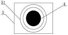
FIG. 3 is a schematic end view of the support bracket;
in the drawings, the reference numbers: 1. a rotor holder; 11. an upper support; 12. a lower support; 2. a rotor position adjusting seat; 3. a rotor mounting hole; 4. a laser light; 5. a support frame; 51. and (6) positioning the circle.
Detailed Description
The invention will be further illustrated with reference to the following specific examples. It should be understood that these examples are for illustrative purposes only and are not intended to limit the scope of the present invention. Further, it should be understood that various changes or modifications of the present invention may be made by those skilled in the art after reading the teaching of the present invention, and these equivalents also fall within the scope of the present application.
Example 1: the invention relates to a tilting pad shaft gap accurate detection tool of a steam turbine generator unit of a power station, which comprises two rotor supporting seats and at least two measuring tools, wherein the measuring tools can adopt a dial indicator or a dial indicator, and the dial indicator or the dial indicator is fixed on a rotor fixing seat 1 through an indicator frame with a magnetic base in order to facilitate the installation of the measuring tools.
As shown in fig. 1, the rotor supporting seat includes a rotor fixing seat 1 and a rotor position adjusting seat 2, the rotor fixing seat 1 is installed at the top of the rotor position adjusting seat 2, and a height adjusting mechanism for adjusting the height of the rotor fixing seat 1 is arranged on the rotor position adjusting seat 2, the height adjusting mechanism may be a scissor jack or other lifting mechanisms, the height adjusting mechanism is preferably a screw elevator, and the axial lead of the worm of the screw elevator is parallel to the axial lead of the mounting hole 3.
Preferably, in order to synchronously lift the rotor fixing seats on the two rotor supporting seats, a detachable synchronous transmission mechanism is arranged between the height adjusting mechanisms on the two rotor position adjusting seats 2, the synchronous transmission mechanism can adopt a synchronous belt, a transmission shaft and the like, after the two rotor fixing seats 1 are adjusted in place, the height adjusting mechanisms on the two rotor position adjusting seats 2 are connected through a synchronous transmission mechanism, when the height adjusting mechanism adopts a spiral elevator, the synchronous transmission mechanism comprises a connecting shaft and a connecting sleeve, spline shafts are fixedly arranged at two ends of the connecting shaft, a spline groove is arranged at one end of the connecting sleeve, a flat key is embedded on the inner wall of the other end of the connecting sleeve, the spline shafts are in sliding connection with the spline groove, the length of the synchronous transmission mechanism can be adjusted, the two ends of the worm of the spiral elevator are respectively provided with a key groove, one end of the worm is provided with a crank, and the other end of the worm is detachably connected with one end of the connecting sleeve, which is inlaid with a flat key.
Be equipped with rotor mounting hole 3 on rotor fixing base 1, the rotor is installed in rotor mounting hole 3, and is preferred, for the installation that makes things convenient for the rotor, rotor fixing base 1 includes upper portion support 11, lower part support 12, pass through bolted connection between lower part support 12 and the upper portion support 11, the bottom of upper portion support 11, the top of lower part support 12 all are equipped with the arc recess, rotor mounting hole 3 is constituteed to the arc recess on upper portion support 11, the lower part support 12.
Use the axle center of rotor mounting hole 3 as the axle center on rotor fixing base 1, the annular array is equipped with a plurality of laser lamp 4 (eight laser lamp 4 have been set up in figure 1), the light that laser lamp 4 sent is parallel with the axial lead of mounting hole 3, and is preferred, for the installation of convenient laser lamp, laser lamp 4 inlays on support frame 5, on the whole inner wall that imbeds mounting hole 3 of support frame 5, also can install laser lamp 4 on rotor fixing base 1's lateral wall.
One of the measuring tools is mounted on the upper side of the rotor mounting hole 3, and the other measuring tool is mounted on the lower side of the mounting hole 3.
The invention adopts two independent rotor supporting seats to support the rotor, can adjust the position of the rotor supporting seats according to the position of the rotor, and the two rotor supporting seats are respectively positioned at the front end and the rear end of the rotor.
Furthermore, in order to be suitable for various places, the bottom of the rotor position adjusting seat 2 is provided with four height-adjustable pad feet which are positioned at four corners of the same rectangle, the axial lead of the mounting hole 3 can be in a horizontal state by adjusting different pad feet, a plane parallel to the axial lead of the mounting hole can be processed at the top of the rotor fixing seat 1, and two mutually vertical level bubbles are embedded on the plane for detecting whether the axial lead of the mounting hole 3 is in a horizontal state or not.
According to the invention, the rotor fixing seat 1 takes the axis of the rotor mounting hole 3 as the axis, the annular array is provided with the plurality of laser lamps 4, the laser lamps 4 on the two rotor supporting seats are all turned on by utilizing a laser alignment principle (figure 2), the laser lamps 4 on the two rotor supporting seats are irradiated oppositely, the light rays of the corresponding laser lamps 4 on the two rotor supporting seats can be superposed by adjusting the positions of the rotor supporting seats and the height of the rotor fixing seat 1, the axial leads of the rotor mounting holes 3 on the two rotor supporting seats can be superposed, and the axial lead of the rotor is ensured to be in a horizontal state.
Preferably, in order to adjust the axial lines of the rotor mounting holes 3 on the two rotor supporting seats to an overlapped state conveniently, a plurality of positioning circles 51 are arranged at the end of the supporting frame 5, the centers of the plurality of positioning circles 51 are overlapped, the light emitted by the laser lamp 4 passes through the center of the positioning circle 51, the positioning circle 51 is used as a scale, the positioning circle 51 is used for positioning the irradiation point of the light, and the position of the rotor supporting seat or the height of the rotor fixing seat 1 is adjusted according to the position of the irradiation point in the positioning circle 51.
Example 2: for finely tuning the horizontal position of rotor fixing base, be equipped with the sharp translation mechanism who is used for adjusting the horizontal position of rotor fixing base 1 on rotor position adjustment seat 2, the horizontal migration direction of rotor fixing base 1 is perpendicular with the axial lead of mounting hole 3, and sharp translation mechanism includes the slide, inlay at the screw of the bottom of slide, inlay the uide bushing in the bottom of slide, with screw matched with lead screw, with uide bushing matched with guide post, the axial lead of lead screw, guide post all is perpendicular with the axial lead of mounting hole 3, the lead screw, the guide post is all installed on rotor position adjustment seat 2, the lead screw rotates with rotor position adjustment seat 2 to be connected, and installs the rotation handle in the one end of lead screw, high adjustment mechanism installs the top at the slide.
Example 3: the use method of the tilting pad axle gap accurate detection device of the power station steam turbine generator unit comprises the following steps:
s1, placing the two rotor supporting seats on two sides of the tilting pad respectively according to the position of the tilting pad, wherein the two rotor supporting seats are symmetrically arranged along the axial direction of the tilting pad;
s2, disassembling the tiltable tile and taking out the rotor;
the disassembling process of the tilting pad comprises the following steps:
s2.1, disassembling and opening the upper tilting pad, taking down the tilting pad shell and a set screw on an adjusting cushion block, marking and keeping properly;
s2.2, taking down the upper adjusting cushion block and the adjusting gasket, winding the cushion block by using silk cloth (or other soft cloth), and then placing the cushion block on the rubber for proper storage;
and S2.3, detaching the upper tilting pad shell, removing the spherical pad pin, the lining pad and the spring, detaching the tilting pad blocks, keeping the tilting pad blocks properly, and taking out the rotor.
S3, mounting one end of the rotor in the rotor mounting hole 3 of one of the rotor supporting seats, and mounting the other end of the rotor in the rotor mounting hole 3 of the other rotor supporting seat;
s4, turning on all the laser lamps 4, and aligning the positions of the two rotor supporting seats by using a laser alignment principle to ensure that the axial leads of the rotor mounting holes 3 on the two rotor supporting seats are overlapped;
s5, reassembling the tilting pad on the rotor;
s6, erecting a measuring tool, wherein the measuring tool can adopt a dial indicator, the position of the measuring tool is adjusted, the measuring head of the measuring tool on the upper side is abutted with the outer wall of the tilting pad shell, the measuring head of the measuring tool on the lower side is abutted with the outer wall of the rotor, and the two measuring tools are reset to zero;
preferably, the axes of the measuring heads of the two measuring tools are perpendicular to and intersect the axis of the rotor.
S7, moving the rotor upwards by using the height adjusting mechanism until the upper side measuring tool has a reading A, recording the reading a of the lower side measuring tool at the moment, and returning the two measuring tools to zero; a can be 0.01mm, namely, the pointer of the dial indicator rotates by a small grid.
S8, moving the rotor downwards by using the height adjusting mechanism until the lower side measuring tool has the reading A, and recording the reading b of the upper side measuring tool at the moment;
s9, calculating a tilting pad axle gap c, c = | a-b |;
and S10, rotating the rotor, repeating the steps S7-S9, obtaining a plurality of tilting pad axle gap values, averaging the tilting pad axle gap values, and taking the average value as the accurate value of the final tilting pad axle gap.
Preferably, in step S10, the rotor is rotated at an angle of 45 ° each time, eight times are measured, and the calculated value of the tilting pad axle gap is averaged out eight times.
Claims (10)
1. Accurate detection outfit of tilting pad axle clearance of power station turbo generator unit, its characterized in that: including two rotor supporting seats, two at least measuring tools, the rotor supporting seat includes rotor fixing base (1), rotor position adjustment seat (2), install in rotor position adjustment seat (2) top rotor fixing base (1), and be equipped with the high adjustment mechanism who is used for adjusting the height of rotor fixing base (1) on rotor position adjustment seat (2), be equipped with rotor mounting hole (3) on rotor fixing base (1), use the axle center of rotor mounting hole (3) as the axle center on rotor fixing base (1), the annular array is equipped with a plurality of laser lamp (4), the light that laser lamp (4) sent is parallel with the axial lead of mounting hole (3), one of them the measuring tool is installed in the upside of rotor mounting hole (3), another one the measuring tool is installed in the downside of mounting hole (3).
2. The accurate detection device for tilting pad axle gap of power station steam turbine generator unit of claim 1, characterized in that: the measuring tool is a dial indicator or a dial indicator, and the dial indicator or the dial indicator is fixed on the rotor fixing seat (1) through an indicator frame with a magnetic base.
3. The accurate detection device for tilting pad axle gap of power station steam turbine generator unit of claim 1, characterized in that: the bottom of the rotor position adjusting seat (2) is provided with four height-adjustable foot pads.
4. The accurate detection device for tilting pad axle gap of power station steam turbine generator unit of claim 1, characterized in that: the laser lamp (4) is embedded on the support frame (5), and the support frame (5) is integrally embedded in the inner wall of the mounting hole (3).
5. The accurate detection device for tilting pad axle gap of power station steam turbine generator unit of claim 4, characterized in that: the tip of support frame (5) is equipped with a plurality of location circle (51), a plurality of the coincidence of the centre of a circle of location circle (51), just the light that laser lamp (4) sent passes the centre of a circle of location circle (51).
6. The accurate detection device for tilting pad axle gap of power station steam turbine generator unit of claim 1, characterized in that: the rotor position adjusting seat (2) is provided with a linear translation mechanism for adjusting the horizontal position of the rotor fixing seat (1), and the horizontal moving direction of the rotor fixing seat (1) is perpendicular to the axis of the mounting hole (3).
7. The accurate detection device for tilting pad axle gap of power station steam turbine generator unit of claim 1, characterized in that: rotor fixing base (1) includes upper portion support (11), lower part support (12) can be dismantled with upper portion support (11) and be connected, the bottom of upper portion support (11), the top of lower part support (12) all are equipped with the arc recess, rotor mounting hole (3) are constituteed to the arc recess on upper portion support (11), lower part support (12).
8. The accurate detection device for tilting pad axle gap of power station steam turbine generator unit of claim 1, characterized in that: a detachable synchronous transmission mechanism is arranged between the height adjusting mechanisms on the two rotor position adjusting seats (2).
9. The use method of the accurate detection device for the tilting pad axle gap of the steam turbine generator unit of the power station as claimed in any one of claims 1 to 8 is characterized by comprising the following steps:
s1, placing the two rotor supporting seats on two sides of the tilting pad respectively according to the position of the tilting pad, wherein the two rotor supporting seats are symmetrically arranged along the axial direction of the tilting pad;
s2, disassembling the tiltable tile and taking out the rotor;
s3, mounting one end of the rotor in the rotor mounting hole (3) of one of the rotor supporting seats, and mounting the other end of the rotor in the rotor mounting hole (3) of the other rotor supporting seat;
s4, turning on a laser lamp (4), and aligning the positions of the two rotor supporting seats by using a laser alignment principle to ensure that the axial leads of the rotor mounting holes (3) on the two rotor supporting seats are overlapped;
s5, reassembling the tilting pad on the rotor;
s6, erecting a measuring tool, adjusting the position of the measuring tool, enabling the measuring head of the measuring tool on the upper side to be abutted against the outer wall of the tilting pad shell, enabling the measuring head of the measuring tool on the lower side to be abutted against the outer wall of the rotor, and enabling the two measuring tools to be reset to zero;
s7, moving the rotor upwards by using the height adjusting mechanism until the upper side measuring tool has a reading A, recording the reading a of the lower side measuring tool at the moment, and returning the two measuring tools to zero;
s8, moving the rotor downwards by using the height adjusting mechanism until the lower side measuring tool has the reading A, and recording the reading b of the upper side measuring tool at the moment;
s9, calculating a tilting pad axle gap c, c = | a-b |;
and S10, rotating the rotor, repeating the steps S7-S9 to obtain a plurality of tilting pad axial gap values, and averaging the obtained tilting pad axial gap values.
10. The use method of the tilting pad axle gap accurate detection device of the power station steam turbine generator unit as claimed in claim 9, wherein in the step S10, the angle of each rotation of the rotor is 45 °.
Priority Applications (2)
| Application Number | Priority Date | Filing Date | Title |
|---|---|---|---|
| CN202210497545.2A CN114593661A (en) | 2022-05-09 | 2022-05-09 | Accurate detection device for tilting pad axle gap of steam turbine generator unit of power station and use method thereof |
| PCT/CN2022/129763 WO2023216527A1 (en) | 2022-05-09 | 2022-11-04 | Appliance for accurately detecting tilting pad clearance of steam turbine generator set of power station and use method therefor |
Applications Claiming Priority (1)
| Application Number | Priority Date | Filing Date | Title |
|---|---|---|---|
| CN202210497545.2A CN114593661A (en) | 2022-05-09 | 2022-05-09 | Accurate detection device for tilting pad axle gap of steam turbine generator unit of power station and use method thereof |
Publications (1)
| Publication Number | Publication Date |
|---|---|
| CN114593661A true CN114593661A (en) | 2022-06-07 |
Family
ID=81821318
Family Applications (1)
| Application Number | Title | Priority Date | Filing Date |
|---|---|---|---|
| CN202210497545.2A Pending CN114593661A (en) | 2022-05-09 | 2022-05-09 | Accurate detection device for tilting pad axle gap of steam turbine generator unit of power station and use method thereof |
Country Status (2)
| Country | Link |
|---|---|
| CN (1) | CN114593661A (en) |
| WO (1) | WO2023216527A1 (en) |
Cited By (1)
| Publication number | Priority date | Publication date | Assignee | Title |
|---|---|---|---|---|
| WO2023216527A1 (en) * | 2022-05-09 | 2023-11-16 | 中国电建集团山东电力建设第一工程有限公司 | Appliance for accurately detecting tilting pad clearance of steam turbine generator set of power station and use method therefor |
Citations (7)
| Publication number | Priority date | Publication date | Assignee | Title |
|---|---|---|---|---|
| CN101859030A (en) * | 2010-05-20 | 2010-10-13 | 浙江大学 | Device and method for coaxially adjusting double beams in real time |
| CN102230962A (en) * | 2011-04-08 | 2011-11-02 | 哈尔滨工业大学 | Laser radar coaxial transmitting and receiving system and coaxial adjustment method thereof |
| CN103017659A (en) * | 2012-12-29 | 2013-04-03 | 中国科学院长春光学精密机械与物理研究所 | Synchronous tiny potential difference and angular difference detection system for combined laser beam emitting light path |
| CN107941126A (en) * | 2018-01-11 | 2018-04-20 | 莱芜钢铁集团有限公司 | Plain bearing bush gap measuring method and device |
| CN209161390U (en) * | 2018-09-27 | 2019-07-26 | 黔西县黔希煤化工投资有限责任公司 | A kind of universal shaft coupling |
| CN211205142U (en) * | 2019-10-30 | 2020-08-07 | 大连派思透平动力科技有限公司 | Tilting pad radial bearing clearance measuring tool |
| CN214456458U (en) * | 2021-03-07 | 2021-10-22 | 呼伦贝尔安泰热电有限责任公司海拉尔热电厂 | Horizontal centrifugal multi-stage pump lifting shaft measuring and adjusting device |
Family Cites Families (8)
| Publication number | Priority date | Publication date | Assignee | Title |
|---|---|---|---|---|
| EP2581615A1 (en) * | 2011-10-14 | 2013-04-17 | Siemens Aktiengesellschaft | Tilting pad radial bearing with an alignment device for a single shaft turbomachine |
| CN106152908B (en) * | 2015-03-25 | 2019-12-31 | 北京福田康明斯发动机有限公司 | Detection tool for bearing bush |
| CN105317471A (en) * | 2015-11-26 | 2016-02-10 | 华电电力科学研究院 | Turbine steam seal clearance adjustment method |
| CN207132832U (en) * | 2017-08-17 | 2018-03-23 | 沈阳工业大学 | A kind of adjustable centrifugal compressor bearing clearance measurement specific purpose tool |
| CN108072308A (en) * | 2017-09-05 | 2018-05-25 | 中国电建集团河南工程有限公司 | Large turbine-generator set shafting radial clearance measures and method of adjustment |
| JP6822994B2 (en) * | 2018-03-08 | 2021-01-27 | 株式会社東芝 | Bearing adjustment support device and bearing adjustment support method |
| CN108917557A (en) * | 2018-07-17 | 2018-11-30 | 哈尔滨电机厂有限责任公司 | A kind of rotor journal natural measurement of tilt method |
| CN114593661A (en) * | 2022-05-09 | 2022-06-07 | 中国电建集团山东电力建设第一工程有限公司 | Accurate detection device for tilting pad axle gap of steam turbine generator unit of power station and use method thereof |
-
2022
- 2022-05-09 CN CN202210497545.2A patent/CN114593661A/en active Pending
- 2022-11-04 WO PCT/CN2022/129763 patent/WO2023216527A1/en unknown
Patent Citations (7)
| Publication number | Priority date | Publication date | Assignee | Title |
|---|---|---|---|---|
| CN101859030A (en) * | 2010-05-20 | 2010-10-13 | 浙江大学 | Device and method for coaxially adjusting double beams in real time |
| CN102230962A (en) * | 2011-04-08 | 2011-11-02 | 哈尔滨工业大学 | Laser radar coaxial transmitting and receiving system and coaxial adjustment method thereof |
| CN103017659A (en) * | 2012-12-29 | 2013-04-03 | 中国科学院长春光学精密机械与物理研究所 | Synchronous tiny potential difference and angular difference detection system for combined laser beam emitting light path |
| CN107941126A (en) * | 2018-01-11 | 2018-04-20 | 莱芜钢铁集团有限公司 | Plain bearing bush gap measuring method and device |
| CN209161390U (en) * | 2018-09-27 | 2019-07-26 | 黔西县黔希煤化工投资有限责任公司 | A kind of universal shaft coupling |
| CN211205142U (en) * | 2019-10-30 | 2020-08-07 | 大连派思透平动力科技有限公司 | Tilting pad radial bearing clearance measuring tool |
| CN214456458U (en) * | 2021-03-07 | 2021-10-22 | 呼伦贝尔安泰热电有限责任公司海拉尔热电厂 | Horizontal centrifugal multi-stage pump lifting shaft measuring and adjusting device |
Cited By (1)
| Publication number | Priority date | Publication date | Assignee | Title |
|---|---|---|---|---|
| WO2023216527A1 (en) * | 2022-05-09 | 2023-11-16 | 中国电建集团山东电力建设第一工程有限公司 | Appliance for accurately detecting tilting pad clearance of steam turbine generator set of power station and use method therefor |
Also Published As
| Publication number | Publication date |
|---|---|
| WO2023216527A1 (en) | 2023-11-16 |
Similar Documents
| Publication | Publication Date | Title |
|---|---|---|
| CN106768639A (en) | Tuning for Controllable Pitch Propeller blade gravity center measurement device and measuring method | |
| CN109186413A (en) | A kind of adjustable spherometer of measurement diameter and radius of curvature and offset measuring method | |
| CN109823568A (en) | A kind of aircraft blade torque automatic measurement system | |
| CN114593661A (en) | Accurate detection device for tilting pad axle gap of steam turbine generator unit of power station and use method thereof | |
| CN110732886A (en) | portable dynamic loading and fine-tuning measuring device based on main shaft rotation precision | |
| CN112501997A (en) | Highway road surface roughness detection device | |
| CN113945164A (en) | Automatic helicopter blade measuring device | |
| CN210464336U (en) | Angle adjusting workbench for measuring angle of flange of bearing inner ring | |
| US5317811A (en) | Apparatus and method for measuring surfaces and lenses | |
| CN215114431U (en) | Cylindricity detection tool for sleeve parts | |
| CN215177403U (en) | Circle run-out length measuring instrument | |
| CN211977745U (en) | Part size inspection equipment | |
| CN110274535B (en) | Outer ring detection device of outer spherical bearing | |
| CN210689488U (en) | Portable symmetry detection device | |
| CN209069222U (en) | Flatness contour degree detection device based on laser three-D profile measurer | |
| CN220708278U (en) | Online detection device for profile of valve rocker assembly support surface and center height | |
| JPH10111105A (en) | Method and device for measuring camshaft | |
| CN217818526U (en) | Portable roundness measuring instrument with guide head | |
| CN211277393U (en) | Portable dynamic loading and fine adjustment measuring device based on main shaft rotation precision | |
| CN216594087U (en) | Measuring device and measuring system for measuring beam angle and luminous flux | |
| CN112629367B (en) | Worm tooth profile and tooth thickness detection device and method | |
| CN114459311B (en) | Silicon ring step detection device | |
| CN220288456U (en) | Fan blade size detection device | |
| CN214199906U (en) | Device for detecting height and inner and outer diameters of stator coil | |
| CN220829166U (en) | Motor core assembly detection mechanism |
Legal Events
| Date | Code | Title | Description |
|---|---|---|---|
| PB01 | Publication | ||
| PB01 | Publication | ||
| SE01 | Entry into force of request for substantive examination | ||
| SE01 | Entry into force of request for substantive examination | ||
| RJ01 | Rejection of invention patent application after publication | ||
| RJ01 | Rejection of invention patent application after publication |
Application publication date: 20220607 |