CN1145819C - Optical system and optical device with said system - Google Patents
Optical system and optical device with said system Download PDFInfo
- Publication number
- CN1145819C CN1145819C CNB99122387XA CN99122387A CN1145819C CN 1145819 C CN1145819 C CN 1145819C CN B99122387X A CNB99122387X A CN B99122387XA CN 99122387 A CN99122387 A CN 99122387A CN 1145819 C CN1145819 C CN 1145819C
- Authority
- CN
- China
- Prior art keywords
- optical
- optical system
- optical element
- surperficial
- optics
- Prior art date
- Legal status (The legal status is an assumption and is not a legal conclusion. Google has not performed a legal analysis and makes no representation as to the accuracy of the status listed.)
- Expired - Fee Related
Links
Images


Classifications
-
- G—PHYSICS
- G02—OPTICS
- G02B—OPTICAL ELEMENTS, SYSTEMS OR APPARATUS
- G02B17/00—Systems with reflecting surfaces, with or without refracting elements
- G02B17/08—Catadioptric systems
- G02B17/0856—Catadioptric systems comprising a refractive element with a reflective surface, the reflection taking place inside the element, e.g. Mangin mirrors
- G02B17/086—Catadioptric systems comprising a refractive element with a reflective surface, the reflection taking place inside the element, e.g. Mangin mirrors wherein the system is made of a single block of optical material, e.g. solid catadioptric systems
-
- G—PHYSICS
- G02—OPTICS
- G02B—OPTICAL ELEMENTS, SYSTEMS OR APPARATUS
- G02B15/00—Optical objectives with means for varying the magnification
- G02B15/14—Optical objectives with means for varying the magnification by axial movement of one or more lenses or groups of lenses relative to the image plane for continuously varying the equivalent focal length of the objective
-
- G—PHYSICS
- G02—OPTICS
- G02B—OPTICAL ELEMENTS, SYSTEMS OR APPARATUS
- G02B17/00—Systems with reflecting surfaces, with or without refracting elements
- G02B17/08—Catadioptric systems
- G02B17/0836—Catadioptric systems using more than three curved mirrors
- G02B17/0848—Catadioptric systems using more than three curved mirrors off-axis or unobscured systems in which not all of the mirrors share a common axis of rotational symmetry, e.g. at least one of the mirrors is warped, tilted or decentered with respect to the other elements
-
- G—PHYSICS
- G02—OPTICS
- G02B—OPTICAL ELEMENTS, SYSTEMS OR APPARATUS
- G02B17/00—Systems with reflecting surfaces, with or without refracting elements
- G02B17/08—Catadioptric systems
- G02B17/0896—Catadioptric systems with variable magnification or multiple imaging planes, including multispectral systems
Abstract
The optical system provided with a first optical part disposed most adjacent to the object side, the optical part having three or more optical surfaces, of which at least one is a reflecting surface, and an aperture stop disposed more adjacent to the image side than the first optical part, wherein when the spacing from the first optical surface to the third optical surface as counted from the object side of the first optical part is defined as D and the spacing from the first optical surface to the entrance pupil at an azimuth [xi] degrees is defined as X([xi]), the following condition is satisfied:[X(0)+X(90)/2]<D. The specification also discloses an optical apparatus provided with such optical system.
Description
Technical field
The present invention relates to the device of a kind of optical system and this system of use, this system is applicable to for example gamma camera, still life gamma camera and copier etc.
Background technology
Only the optical system that is made of a refractor can be used as a kind of image pickup optical system with zoom function.In this optical system, dispose a kind of sphere or rotational symmetric aspheric surface refractor symmetrically with respect to this lens axis rotation.
Known also has, and a plurality of reflectings surface that constitute a minute surface optical system by relatively moving change the zoom technology of the imaging enlargement factor (focal length) of optical system.
For example, U.S. Pat 4,812,030 discloses a kind of utilization relatively changes concave mirror 101 to the spacing between the convex mirror 102, and concave mirror 102 implements to change the technology of optical system focal length to resembling the spacing of surface between 103, and it is as shown in Figure 17 a kind of cassegrain reflector structure that these minute surfaces constitute.
Figure 18 is illustrated in disclosed another kind of embodiment in the above-mentioned patent.In Figure 18, be incident on first concave mirror 121 and from the object beam 128 of object by its surface reflection, become a branch of converging light, directive object one side also is incident on first convex mirror 122, reflex to imaging surface one side again, becoming a branch of is parallel light beam basically, is incident to second convex mirror 124, again by its surface reflection, become a branch of divergent beams, and be incident to second concave mirror 125, by its reflection, become a branch of convergent beam, imaging on imaging surface 127.
In this structure, by the spacing between first concave mirror 121 and first convex mirror 122, and the change of spacing can be implemented the zoom of the minute surface optical system of zoom and total system between second convex mirror 124 and second concave mirror 125.
In U.S. Pat 4,993, in 818, by resembling that cassegrain reflector (shown in Figure 17) forms, give secondary imaging by other minute surface optical system that provides by the back one-level, change the imaging amplification of this secondary imaging minute surface optical system, just can implement the zoom of whole optical system.
These reflection optical systems need a large amount of component parts, to obtain necessary optical property, also need assemble each optics with good precision.Especially, the relative positioning precision of catoptron is quite strict, so need to regulate the position and the angle of each catoptron.
Propose as solution to this problem, for example a kind ofly an integral body is made by the minute surface system, the method for each optics assembly error when avoiding assembling thus.
Figure 19 is illustrated in the embodiment of disclosed a kind of reflective optics among the Japanese publication application NO.8-292368.In Figure 19, from the light beam of the object first surface R1 by diaphragm, this light beam enters the first optical element B1.In the first optical element B1, light beam is subjected to the refraction of second surface R2, and by the reflection of the 3rd surperficial R3 and the 4th surperficial R4, again by the 5th surface refraction, thereby penetrates from the first optical element B1.At this moment, this light beam by elementary imaging near on the middle imaging surface on the 4th surface.
Afterwards, light beam enters the second optical element B2.In the second optical element B2, light beam, is penetrated again by the 9th surperficial R9 refraction, and from the second optical element B2 by the 7th surperficial R7 and the 8th surperficial R8 reflection by the 6th surperficial R6 refraction.At this moment, in the second optical element B2, form a pupil near the 7th surperficial R7 place.The final imaging of penetrating from the second optical element B2 of light beam is resembling on the face P (image pickup medium such as CCD videotape surface).
In this embodiment, the first optical element B1 is instant along moving towards the Z positive dirction of the end of dolly-out,ing dolly-back from wide-angle side during zoom, moves along the Z negative direction more afterwards.The second optical element B2 along the Z negative direction from wide-angle side to the end motion of dolly-out,ing dolly-back.Resembling surperficial P when zoom does not move.Distance between the first optical element B1 and the second optical element B2 is owing to focal length narrows down from the change of wide-angle side to the end of dolly-out,ing dolly-back, and the second optical element B2 and the distance that resembles between the surperficial P broaden.
In the present invention, adopt a plurality of optical elements, the reflecting surface of wherein a plurality of curved surface peace forms with integral body mutually, at least two relative positions in a plurality of optical elements are suitably changed, to carry out zoom, make the size of whole minute surface optical system descend thus, and the requirement of the positional precision (assembly precision) of catoptron in the minute surface optical system is relaxed.
Equally, adopt and a kind ofly unify the structure that side is provided with diaphragm in the optical system of close object, in this optical system, image at least once forms, no matter whether the varifocal optical system of reflection-type has wide visual angle, the effective diameter of optical system will reduce, and provide suitable reflectivity to a plurality of reflecting surfaces that constitute optical element, the reflecting surface that only constitutes each optical element needs to be provided with prejudicially, make the light path in the optical system be bent to required shape thus, and shorten the length of whole optical system along predetermined direction.
Have only situation about often having in the optical system of a refraction optical element to be existing, entrance pupil is embedded in the optical system, thereby the problem that exists is, the distance of the incidence surface from diaphragm to the most contiguous thing side becomes big, makes to become big at the effective diameter with the light beam on the incidence surface that adds with great visual angle.
In addition, in above-mentioned U.S. Pat 4,812,030 and 4, disclosed minute surface optical system in 993,818 with zoom function, it had both needed a large amount of component parts that comprises catoptron and imaging lens, also requirement obtains necessary optical property, and this just need assemble each optics with good precision.
Equally, the relative positional accuracy of each catoptron is especially strict, so need regulate the position and the angle of each catoptron.
In addition, disclosed optical system in above-mentioned Japan publication application NO.8-292372, its characteristics are that the size of whole minute surface optical system is descended.And the bearing accuracy (assembly precision) that makes each catoptron in the minute surface optical system requires to reduce.In the optical system of this patented claim, the position of diaphragm and entrance pupil is identical, so be constant in order to make the F number when zoom, just needs to change the diameter of diaphragm.Equally, if the F number is determined that then the diameter of diaphragm is just determined, and when the size of image as in the still life gamma camera hour, it is very little that the diameter of little diaphragm need become.
Summary of the invention
Based on above-mentioned prior art, the object of the present invention is to provide a kind of optical system, it can prevent the reduction of edge light quantity, and the diameter that prevents little diaphragm becomes quite little, even and when zoom the fixed diameter of diaphragm, the F number also is essentially constant, and makes the size of optical system drop to the degree of optical system that is arranged on the preposition diaphragm of adjacent object one side as diaphragm.
For achieving the above object, optical system of the present invention has first opticator that is arranged on the most contiguous thing side, aperture diaphragm is arranged on the side than its more contiguous elephant, it is characterized in that this optical system is constituted as, its entrance pupil can be positioned at the first surface place near first opticator, and this surface is the surface of the most contiguous thing side of this optical system.
Particularly, the invention provides a kind of optical system, have: one first optics, be arranged on the most contiguous thing side, described first optics has the optical surface more than three or three, and wherein at least one surface is a reflecting surface; And an aperture diaphragm, it is provided with to such an extent that more be adjacent to than described first optics and resemble side; Wherein be defined as D when spacing from the thing side number of described first optics from first optical surface to the, three optical surfaces, and when described first optical surface to the spacing with respect to the entrance pupil of the position angle ξ degree of axis of reference was defined as X (ξ), following condition was met: | [X (0)+X (90)]/2|<D.
The present invention also provides a kind of optical devices that above-mentioned optical system is housed.
Description of drawings
Fig. 1 is the optical cross section view of the embodiment of the invention 1 in the YZ face.
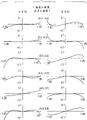
Fig. 2 is the lateral aberration curve (wide-angle side) of embodiment 1.
Fig. 3 is the lateral aberration curve (centre position) of embodiment 1.
Fig. 4 is the lateral aberration curve (end of dolly-out,ing dolly-back) of embodiment 1.
Fig. 5 is the optical cross section view of the embodiment of the invention 2 in the YZ face.
Fig. 6 is the lateral aberration curve (wide-angle side) of embodiment 2.
Fig. 7 is the lateral aberration curve (centre position) of embodiment 2.
Fig. 8 is the lateral aberration curve (end of dolly-out,ing dolly-back) of embodiment 2.
Fig. 9 is the optical cross section view of the embodiment of the invention 3 in the YZ face.
Figure 10 is the lateral aberration curve (wide-angle side) of embodiment 3.
Figure 11 is the lateral aberration curve (centre position) of embodiment 3.
Figure 12 is the lateral aberration curve (end of dolly-out,ing dolly-back) of embodiment 3.
Figure 13 represents that the embodiment of the invention 1 is in the lip-deep illumination of resembling of wide-angle side X-axis.
Figure 14 represents that the embodiment of the invention 2 is in the lip-deep illumination of resembling of wide-angle side X-axis.
Figure 15 represents that the embodiment of the invention 3 is in the lip-deep illumination of resembling of wide-angle side X-axis.
Figure 16 is a coordinate system key diagram in the embodiment of the invention.
Figure 17 represents the basic structure of cassegrain reflector.
Figure 18 is the optical system synoptic diagram of existing use catoptron.
Figure 19 is illustrated in the photographic optical system that has curvature in the existing prismatic reflection surface.
Embodiment
Before beginning to introduce present embodiment, with the term of the common employing of composition data and whole embodiment institute of the present embodiment of explanation expression earlier.
Figure 16 represents a coordinate system, and it limits the structured data of optical system of the present invention.In embodiments of the present invention, along being defined as the i surface in embodiments of the present invention from thing side to the i surface that resembles on the light (refer to the dot-and-dash line Figure 16 and be called as reference axis) of advancing on the surface.
In Figure 16, first surface R1 is a refractive surface, second surface R2 is a reflecting surface that tilts with respect to first surface R1, the 3rd surperficial R3 and the 4th surperficial R4 are that the 5th surperficial R5 is a refractive surface with respect to the 4th surface displacement and inclination with respect to their front-surface displacement and the reflecting surface that tilts.First surface R1 to the five surperficial R5 are formed on the optical element of being made up of for example glass or plastic medium, and in Figure 16, this optical element is optical element B1.
So in the formation of Figure 16, form by air from thing surface (not shown) to the medium between the first surface R1, form by certain common medium from the medium of first surface R1 to the five surperficial R5, form by air from the medium (not shown) between the 5th surperficial R5 to the six surperficial R6.
In the optical system of present embodiment, the surface that constitutes optical system does not have a common optical axis.So, in the embodiment of the invention, at first set an absolute dimension system at center as original coordinate system with first surface.
In embodiments of the present invention, the central point of first surface (reference axis and first surface intersect point) is defined as initial point, simultaneously by the center of diaphragm and at last the path of the light (axis of reference light) at the center of imaging surface be defined as the axis of reference of optical system.In addition, the axis of reference of present embodiment has a direction, and this direction is a direction that axis of reference light is advanced when imaging.
And in an embodiment of the present invention, set axis of reference with the object of reference of setting optical system as mentioned above, this is convenient to optical design, adjusts each surperficial shape of aberration or expression formation optical system, and can be used as the axle of optical system reference.Yet, will be set at the reference axis of optical system reference by the opticpath that resembles the surface and the center of diaphragm (or entrance pupil, or emergent pupil, or the center of the first surface of optical system, or centre of surface) at last usually.
In the present embodiment, promptly the path of the center by first surface to the center of the last imaging surface light of advancing is reflected by each plane of refraction and each reflecting surface and is reflected along light (axis of reference light), and this path setting is an axis of reference.The order on each surface is set at the order that axis of reference light is reflected and reflects.
So, when the direction of axis of reference changes in proper order according to refraction or reflection law setting surfacewise, the final center that resembles the surface that arrives of axis of reference.
The inclined surface that all constitute the optical system of each embodiment of the present invention tilts in same plane basically.So it is as follows to define a kind of axle of absolute dimension system:
The Z axle: straight line, by the center on initial point and thing surface.Direction from the thing surface towards first surface R1 is for just.
Y-axis: straight line, by initial point, and interior from the dip plane (drawing shown in Figure 16) that drawing is observed with respect to the counterclockwise 90 ° of formation of Z axle.
X-axis: straight line, by initial point, and perpendicular to Z axle and Y-axis (perpendicular to the straight line of Figure 16 drawing).
In addition, constitute the surface configuration on the i surface of optical system for expression, the focusing coordinate system that setting has an axis of reference and i surface initial point intersecting each other is the shape of identified surface more easily just, and the surface configuration of representing the i surface by the local coordinate system is than being represented that by absolute dimension system this surperficial shape comes easily, thereby i surperficial surface configuration represented by the local coordinate system.
In addition, with θ i angle (unit degree of being " ° ") expression inclination angle of i surface in the YZ face, in this face, the counter clockwise direction with respect to the Z axle of absolute dimension system during from drawing just is.So in embodiments of the present invention, the initial point of the local coordinate that each is surperficial is in Figure 16 on the YZ face.Surface in XZ and XY face does not have degree of eccentricity.Also have, in the YZ face Y of the local coordinate on i surface (X, Y, Z) and Z axle with respect to absolute coordinates system (x, y z) have the inclination that angle is θ i, and it specifically is set as follows:
The Z axle: straight line by the initial point of local coordinate, during from drawing, forms θ i angle with respect to the Z direction in counterclockwise mode in the YZ face.
Y-axis: straight line by the initial point of local coordinate, during from drawing, forms 90 degree in counterclockwise mode with respect to the Z direction in the YZ face.
X-axis: straight line, by the initial point of local coordinate, and perpendicular to the YZ face.
And Di is a scalar at interval between the initial point of the local coordinate on expression i surface and (i+1) surface, and Ndi and ν di represent the refractive index and the abbe number (Abbe number) of medium between i surface and (i+1) surface respectively.
In addition, the optical system of the embodiment of the invention utilizes the motion of a plurality of optical elements to change whole focal length (carrying out the change of focal length).In a special case of the present invention (below introduction), represent three kinds of locational sectional views and three positions, i.e. wide-angle side (W), the data value of this optical system when dolly-out,ing dolly-back end (T) and centre position (M).
In optical element shown in Figure 16, this optical element is at the YZ in-plane moving, it is the initial point (Yi of the local coordinate of each surface location of expression, Zi), its value is changed at each zoom position place, and in embodiments of the present invention, the optical element of focal length motion for a change only moves in the Z direction, so by coordinate values Zi (W), Zi(M) and Zi (T) represent coordinate values Zi by wide-angle state, the intermediateness of optical system and the order of the state of dolly-out,ing dolly-back.
Each surperficial coordinate values is represented as the value in value, centre position of wide-angle side and the value of the end of dolly-out,ing dolly-back, and has described the difference with wide-angle side.Especially, if when being a and b respectively with respect to the amount of exercise of wide-angle side (W) (M) and the end (T) of dolly-out,ing dolly-back in the centre position, then coordinate values is explained by following formula:
Zi(M)=Zi(W)+a
Zi(T)=Zi(W)+b
As for the symbol of a and b, each surface when the Z positive dirction is moved for just, and when the Z negative direction is moved for negative.The spaced surface Di that changes along with this motion can obtain, and in the table below the Di value of zoom position is summarised in separately.
The optical system of the embodiment of the invention has a sphere and the asymmetric aspheric surface of rotation.As for land portions, its radius of curvature R i is write as spherical shape.When the center of curvature be arranged in along the first surface side of considering axle and from first surface to resembling the surface when advancing (Figure 16 dot-and-dash line), the symbol of radius of curvature R i is born, when the center of curvature is positioned at when resembling the face side, the symbol of radius of curvature R i is positive.
Expression is represented the shape of spherical surface:
In addition, optical system of the present invention has an asymmetric aspheric surface of rotation at least, and its shape is explained by following formula:
Z=C02y
2+C20x
2+C03y
3+C21x
2y+C04y
4+C22x
2y
2+
C40x
4+C05y
5+C23x
2y
3+C41x
4y+C06y
6+
C24x
2y
4+C42x
4y
2+C60x
6
Above-mentioned representation of a surface formula has only even number time for X, thus the curved surface of describing with above-mentioned representation of a surface formula be one have the YZ face as the plane of symmetry in the face of the title shape.Also have, with respect to the XZ face, curved surface is the face of a shape symmetry when satisfying following formula:
C03=C21=t=0
In addition, when following condition satisfied, curved surface was the face of a rotation symmetric shape:
C02=C20 C04=C40=C22/2
C06=C60=C24/3=C42/3
When above-mentioned condition did not satisfy, curved surface was the face of an asymmetric shape of rotation.
In each embodiment of the present invention, the half angle of view uY of level is the maximum visual angle that enters the face R1 light beam in the YZ face of Figure 16, and vertical half angle of view uX is the maximum visual angle that enters the light beam of the face R1 in the XZ face of Figure 16.Simultaneously, the diameter of diaphragm is expressed as aperture diameter.These situations relate to the brightness of optical system.
In addition, resembling the lip-deep domain representation that effectively resembles for resembling size.Dimension of picture is represented that by a rectangular area size in this area in the y direction of local coordinate is a level, and the size in the directions X of local coordinate is vertical.
To introduce the lateral aberration curve of each embodiment below.The lateral aberration curve representation is being incident to surperficial R
1The vertical incidence angle and the glancing incidence angle respectively with respect to wide-angle side (W) state of each embodiment, centre position (M) and the end (T) of dolly-out,ing dolly-back be (o ,-uY), (o, o), (o, uY), (uX ,-uY), (uX, o) and (uX, uY) under the situation, the lateral aberration of beam incident angle.In the lateral aberration curve, axis of abscissa is represented the height of incidence of pupil, and Y axis Y is represented the aberration amount.In each embodiment, each surface be basically one have the yz face as symmetrical surface in the face of claiming shape, so in the lateral aberration curve, the positive and negative direction of vertical angle of view is identical, also be applicable to the enlargement factor of expression, be not shown in the lateral aberration curve of negative direction among the figure.
To introduce the characteristics of representing its essential characteristic most that optical system had in the various embodiments of the present invention below.
Optical system of the present invention is one and has first opticator that the most contiguous its thing side is provided with, one than its more close optical system that resembles the aperture diaphragm of side setting, this optical system is constituted as, its entrance pupil can be positioned at the first surface place near first opticator, first surface is the surface of the most contiguous thing side of this optical system, can prevent the decline of edge light quantity thus, and the diameter that prevents little diaphragm becomes quite little, even this aperture diameter is fixed when zoom, the F number also is essentially constant, the size of first opticator also can drop to as being equipped with the identical degree of optical system of diaphragm in the thing side of first opticator, and can realize further that the size of whole optical system descends.
The position of entrance pupil especially need be described, this design of Optical System becomes, when the spacing from first optical surface (first surface) be considered as from the spacing of thing side to the three optical surfaces (the 3rd surface) of first opticator be defined as the D value (on the occasion of), and being defined as X (ξ) from first surface to the spacing with respect to the entrance pupil of the position angle ξ degree of axis of reference (notes, X (ξ) entrance pupil be positioned at take when resembling side rather than first surface place on the occasion of, and when entrance pupil is positioned at thing side rather than first surface place, take negative value) time, satisfy following condition:
|〔X(0)+X(90)〕/2|<D ...(1)
That is, entrance pupil be positioned at apart from first surface ± the D value.
In the present embodiment, although comprise by each optical surface be the yz face the inside (interior) of face of crooked axis of reference light for being restricted to ξ=0 (degree) for simplicity, the present invention is not limited to this qualification.That is to say that the left side of above-mentioned conditional is illustrated in the mean place of the entrance pupil in any two mutually perpendicular, exist in the first surface distance D of first opticator.
To introduce each embodiment of the present invention specially below.
Fig. 1 is the optical cross section figures of embodiments of the invention 1 in its yz face.This embodiment is the image pickup optical system of the three-unit zoom lens of about three times of variable powers, and it comprises optical element B1, B2 and the B3 of three solid builds.Its structured data is as follows:
The middle end of dolly-out,ing dolly-back of wide-angle side
Horizontal half angle of view 26.3 13.9 9.3
Vertically look squarely angle 20.3 10.5 7.0
Diaphragm diameter 1.82 1.82 1.82
Resemble size, level * vertical 3.554mm * 2.666mm
First optical element: B1
i Yi Zi(W) θi Di Ndi νdi
1 0.00 1.00 0.00 12.80 1.57250 57.76 planes of refraction
2 0.00 13.80 32.91 9.00 1.57250 57.76 reflectings surface
3-8.21 10.11 16.95 9.00 1.57250 57.76 reflectings surface
4-12.97 17.75 0.14 8.50 1.57250 57.76 reflectings surface
5-17.50 10.56-19.56 8.50 1.57250 57.76 reflectings surface
6-25.55 13.28-35.53 5.20 1.57250 57.76 reflectings surface
7-25.58 8.08 0.28 1 variable planes of refraction
Second optical element: B2
8-25.59 5.08 0.28 5.50 1.57250 57.76 planes of refraction
9-25.62-0.42 38.01 7.20 1.57250 57.76 reflectings surface
10-18.64 1.35 37.25 7.20 1.57250 57.76 reflectings surface
11-18.48-5.84 33.44 6.80 1.57250 57.76 reflectings surface
12-12.17-3.31 34.24 5.50 1.57250 57.76 reflectings surface
13-12.21-8.81 0.37 1 variable planes of refraction
Diaphragm
14-12.27-18.32 0.37 1 variable diaphragms
The 3rd optical element: B3
15-12.28-20.32 0.37 6.60 1.57250 57.76 planes of refraction
16-12.33-26.92-35.35 9.60 1.57250 57.76 reflectings surface
17-21.41-23.80-20.80 10.00 1.57250 57.76 reflectings surface
18-26.33-32.51-6.23 9.50 1.57250 57.76 reflectings surface
19-32.68-25.44 11.22 10.00 1.57250 57.76 reflectings surface
20-41.70-29.77-32.17 5.00 1.57250 57.76 reflectings surface
21-41.70-24.77-0.04 1 variable plane of refraction
The optical correction plate
22-41.69-20.72 0.00 4.00 1.51633 64.15 planes of refraction
23-41.69-16.72 0.00 1.00 1 planes of refraction
Resemble the surface
P-41.69-15.72-0.00 1 resembles the surface
The middle end of dolly-out,ing dolly-back of wide-angle side
D7 3.00 6.82 8.75
D13 9.51 5.38 2.71
D14 2.00 2.57 2.00
D21 4.05 4.31 3.00
D1 to 7 surface: Zi (M)=Zi (W)-0.00 Zi (T)=Zi (W)-0.00
D8 to 13 surface: Zi (M)=Zi (W)-3.82 Zi (T)=Zi (W)-5.75
D14 to 14 surface: Zi (M)=Zi (W)+0.31 Zi (T)=Zi (W)+1.05
D15 to 21 surface: Zi (M)=Zi (W)-0.26 Zi (T)=Zi (W)+1.05
D22 surface: Zi (M)=Zi (W) Zi (T)=Zi (W)
Spherical shape
Surface R1 r1=-10.000
Surface R7 r7=-15.561
Surface R8 r8=34.119
Surface R13 r13=8.858
Surface R15 r15=26.889
Surface R21 r21=9.484
Aspherical shape
Surface R2 C02=-2.12342e-02 C20=-4.20269e-02
C03=1.81374e-04 C21=9.17118e-05
C04=1.85211e-05 C22=-2.40729e-05 C40=-6.48161e-05
Surface R3 C02=-7.61864e-03 C20=-9.02818e-02
C03=1.92614e-04 C21=-1.72415e-03
C04=-2.70968e-04 C22=-1.24810e-03 C40=1.09034e-02
Surface R4 C02=-2.43274e-02 C20=-4.36675e-02
C03=6.68845e-05 C21=-5.93107e-04
C04=-6.16416e-05 C22=-1.24891e-04 C40=-1.39581e-04
Surface R5 C02=-1.84925e-02 C20=-8.18249e-03
C03=-1.08792e-04 C21=1.60755e-03
C04=-1.79570e-04 C22=-1.21026e-03 C40=-4.14091e-04
Surface R6 C02=-2.65562e-02 C20=-2.11329e-02
C03=7.38808e-05 C21=2.82041e-04
C04=-3.46320e-05 C22=-2.49266e-04 C40=2.48610e-05
Surface R9 C02=2.43116e-02 C20=3.12150e-02
C03=8.60449e-04 C21=-1.74279e-03
C04=6.03223e-05 C22=-1.46771e-04 C40=7.87587e-05
Surface R10 C02=-2.50756e-02 C20=8.47992e-04
C03=9.16289e-06 C21=-6.12416e-03
C04=-6.54263e-05 C22=-1.77537e-04 C40=2.46426e-04
Surface R11 C02=4.04553e-02 C20=4.59632e-02
C03=-1.85442e-03 C21=2.67661e-03
C04=4.88193e-04 C22=1.23645e-03 C40=-6.35068e-05
Surface R12 C02=-2.90408e-02 C20=-8.00000e-02
C03=-6.81882e-05 C21=1.16013e-02
C04=3.36006e-04 C22=-2.43191e-03 C40=8.31150e-04
Surface R16 C02=1.87672e-02 C20=5.27232e-02
C03=1.12373e-04 C21=-1.64190e-03
C04=1.89013e-05 C22=5.46061e-05 C40=2.11500e-04
Surface R17 C02=5.63146e-03 C20=-4.66337e-02
C03=9.10393e-04 C21=-1.82539e-03
C04=3.21114e-05 C22=-7.82380e-04 C40=4.32072e-04
Surface R18 C02=2.34915e-02 C20=2.96401e-02
C03=-2.98888e-04 C21=1.64372e-03
C04=1.33834e-04 C22=1.42034e-04 C40=7.77143e-06
Surface R19 C02=-2.63915e-03 C20=-5.37233e-03
C03=-1.99724e-03 C21=3.35104e-03
C04=2.06405e-04 C22=1.27901e-04 C40=6.50230e-05
Surface R20 C02=2.84444e-02 C20=8.06324e-03
C03=-4.36035e-04 C21=-9.98362e-04
C04=8.30716e-06 C22=1.99710e-04 C40=1.40741e-04
In Fig. 1, first surface R1 to the seven surperficial R7 constitute the first optical element B1 together, and the 8th surperficial R8 to the 13 surperficial R13 constitute the second optical element B2 together, and the 15 surperficial R15 to the 21 surperficial R21 constitute the 3rd optical element B3 together.Among the optical element B1-B3 each is made up of the optical unit piece of a complete transparent body, and optical element B1 is equivalent to first opticator of the present invention.
The 14 surperficial R14 is a diaphragm, is set at the more contiguous side that resembles than optical element B1, and between optical element B2 and optical element B3.B4 is an optical correction plate, and it is made of a parallel flat, and comprises a low-pass filter, an IR-cut filter etc., and used material is quartzy.
Letter P represents a visual receiving element surface, and it is the last surface that resembles, and for example it is the visual receiving surface of a kind of CCD (image pickup medium) etc.
Imaging effect in the time of will introducing object below and be positioned at unlimited distance.At first, enter the refractive surface R1 of the first optical element B1 from the light beam of object.In the first optical element B1, light is by first surface R1 refraction, by second surface R2, the 3rd surperficial R3, the 4th surperficial R4, the 5th surperficial R5 and the 6th surperficial R6 reflection, by the 7th surperficial R7 refraction, again from the first optical element B1 outgoing.In the present embodiment, light beam forms an entrance pupil between first surface R1 and second surface R2.And light beam is forming a pupil near the 7th surperficial R7 place.Light beam becomes intermediate image between the 3rd surperficial R3 and the 4th surperficial R4 simultaneously.
Afterwards, light beam enters the refractive surface R8 of the second optical element B2.In the second optical element B2, light beam, is reflected by the 13 surperficial R13 by the 9th surperficial R9, the tenth surperficial R10, the 11 surperficial R11 and the 12 surperficial R12 reflection by the 8th surperficial R8 refraction, and from the second optical element B2 outgoing.Light beam is imaging surface in the middle of having one near the 9th surperficial R9 with near the 12 surperficial R12 place.Light beam is forming a pupil near the tenth surperficial R10 place simultaneously.
Afterwards, the light beam that penetrates from the second optical element B2 enters the refractive surface R15 of the 3rd optical element B3 again by the 14 surperficial R14 as diaphragm.In the 3rd optical element B3, light beam is by the 15 surperficial R15 refraction, by the 16 surperficial R16, the 17 surperficial R17, the 18 surperficial R18, the 19 surperficial R19 and the 20 surperficial R20 reflection, again by the 21 surperficial R21 refraction, at last from the 3rd optical element B2 outgoing.Light beam is forming a pupil near the 19 surperficial R19 place.In addition, light beam is becoming intermediate image near the 18 surperficial R18 place.
At last, by optical correction plate B4, imaging is on imaging surface P again from the light beam of the 3rd optical element B3 outgoing.
To introduce motion below by caused each optical element of zoom operation.When zoom, the first optical element B1 maintains static.The second optical element B2 moves along the negative direction of Z, cause thus focal length from wide-angle side to the change of end of dolly-out,ing dolly-back, and utilize the motion of the 3rd optical element and focus on again to proofread and correct and resemble surperficial fluctuating because the change of focal length is caused.Resembling surperficial P in the process of zoom does not move.The first optical element B1 is equivalent to the supplementary lens of so-called photographic optical system, and the second optical element B2 is equivalent to a kind of so-called varifocal mirror, and the 3rd optical element B3 is equivalent to a compensator.
Fig. 2,3 and 4 is lateral aberration curve maps of present embodiment.
To introduce the effect of present embodiment below.
Diaphragm R14 is provided at resembling on the side of the first optical element B1, and between the second optical element B2 and the 3rd optical element B3, so even the fixed diameter of diaphragm and zoom to 3.64-10.92mm, the F number approaches 2.8 and be constant.
Figure 13 is illustrated in the wide-angle side of present embodiment, resemble the illumination on the X-axis of local coordinate on surface, its Y axis Y represents to resemble lip-deep illumination when light quantity is 100 in the center, axis of abscissa represents to resemble when size is 100 when resembling of directions X 1/2nd position on surface.
When diaphragm places the thing side of adjacent optical system, there is not the pupil aberration, so reduce the edge light quantity according to cosine the 4th law.In the present embodiment, as shown in figure 13, than cosine the 4th law, the edge light quantity obtains about 20% improvement.
In addition, in wide-angle side, it is 1.4 times at the imaging magnification of stop position entrance pupil.When diaphragm placed the thing side of adjacent optical system, the size of entrance pupil was exactly the diameter of diaphragm fully, but in the present embodiment, its size is 1.4 times of diaphragm.
That is to say that the diameter of little diaphragm is unlikely to become very little.
And, a kind of when making resembling of diaphragm R14 be formed on the structure of thing side when adopting by optical element B2 and B1, by optical system (optical element B2, B1) feasible imaging with negative amplification is carried out towards the stop position, effective diameter at each surperficial glazed thread is compressed into a little numerical value, thereby obtains the structural compactness to each optical element and whole camera optical system.
In the present embodiment, the space D from first surface to the three surfaces is:
D=D1+D2=21.8
And average headway from first surface to entrance pupil | [X (0)+X (90)]/2|,
In wide-angle side be
|X(0)+X(90)]/2|=|(2.91+0.90)/2|≈1.90<D。
In the centre position be
|[X(0)+X(90)]/2|=|(3.67+0.32)/2|≈2.00<D,
End is dolly-out,ing dolly-back
|[X(0)+X(90)]/2|=|(1.99+1.50)/2|≈1.75<D。
Therefore, the optical system of embodiment 1 is in the whole zoom area formula (1) that satisfies condition, and entrance pupil is positioned near the optical surface of the most contiguous thing side, thereby realizes the decline of the effective diameter of optical system.
In the present embodiment, diaphragm R14 is between the second optical element B2 and the 3rd optical element B3, if but the change of paraxial layout also can provide diaphragm between the first optical element B1 and the second optical element B2.
Fig. 5 is the embodiment of the invention 2 optical cross section figure in the yz face.This embodiment is the image pickup optical system of a three-unit zoom lens, utilizes three hollow type optical elements that include a plurality of front-surface mirrors that zoom lens are had and is about three times variable power.To be represented its structured data below.
The middle end of dolly-out,ing dolly-back of wide-angle side
Horizontal half angle of view 19.1 9.8 6.6
Vertical half angle of view 14.5 7.4 4.9
Diaphragm diameter 2.6 2.6 2.6
First optical element: B1
i Yi Zi(W) θi Di Ndi νdi
1 0.00 15.31 31.30 9.92 1 reflectings surface
2-8.81 10.75 14.98 9.92 1 reflectings surface
3-14.15 19.10-1.81 10.00 1 reflectings surface
4-19.01 10.36-16.67 9.96 1 reflectings surface
5-27.83 14.98-31.18-31.18 1 reflectings surface
Second optical element: B2
6-27.83-3.81 36.09 9.56 1 reflectings surface
7-18.73-0.88 34.40 9.18 1 reflectings surface
8-18.18-10.05 27.88 9.37 1 reflectings surface
9-10.14-5.24 29.56 1 variable reflectings surface
Diaphragm
10-10.14-30.37 0.00 1 variable diaphragms
The 3rd optical element: B3
11-10.14-40.40-35.72 13.71 1 reflectings surface
12-23.15-36.04-21.17 14.29 1 reflectings surface
13-30.10-48.52-3.60 13.57 1 reflectings surface
14-38.13-37.58 11.86 14.29 1 planes of refraction
15-50.51-44.72 29.80 1 variable planes of refraction
The optical correction plate
16-50.65-29.35-0.06 5.71 1.51633 64.15 reflectings surface
17-50.66-23.64-0.06 1.43 1 reflectings surface
Resemble the surface
P-50.66-22.21-0.06 1 resembles the surface
The middle end of dolly-out,ing dolly-back of wide-angle side
D5 18.79 27.11 31.34
D9 25.13 18.66 14.09
D10 10.03 9.73 9.79
D15 15.37 16.91 16.63
The surperficial Zi of D1 to 5 (M)=Zi (W)-0.00 Zi (T)=Zi (W)-0.00
The surperficial Zi of D6 to 9 (M)=Zi (W)-8.32 Zi (T)=Zi (W)-12.55
D10 surface Zi (M)=Zi (W)-1.85 Zi (T)=Zi (W)-1.51
The surperficial Zi of D11 to 15 (M)=Zi (W)-1.55 Zi (T)=Zi (W)-1.26
P Zi(M)=Zi(W) Zi(T)=Zi(W)
Aspherical shape
Surface R1 C02=-1.80239e-02 C20=-2.81931e-02
C03=2.44018e-04 C21=-5.43047e-04
C04=-2.32825e-05 C22=1.72384e-05 C40=-5.19185e-04
Surface R2 C02=-6.90964e-03 C20=1.41392e-02
C03=1.24650e-04 C21=4.47556e-04
C04=-2.20542e-06 C22=1.29393e-04 C40=-1.71792e-03
Surface R3 C02=-1.69001e-02 C20=-3.56762e-02
C03=4.96628e-05 C21=-1.58142e-04
C04=-3.11289e-05 C22=-5.12061e-05 C40=-9.06178e-05
Surface R4 C02=-1.15275e-02 C20=-9.34471e-03
C03=4.30564e-05 C21=5.48380e-03
C04=-1.00934e-04 C22=-7.58584e-04 C40=-1.25938e-03
Surface R5 C02=-1.85162e-02 C20=-2.48531e-02
C03=2.16240e-06 C21=-2.04418e-04
C04=-9.49313e-06 C22=-2.33936e-04 C40=1.51644e-04
Surface R6 C02=1.43123e-02 C20=2.40374e-02
C03=2.10298e-04 C21=-1.07025e-04
C04=-7.74728e-06 C22=-1.02603e-04 C40=1.89928e-05
Surface R7 C02=-1.80425e-02 C20=3.64565e-03
C03=-5.39315e-04 C21=-4.19921e-03
C04=-1.09354e-04 C22=-3.01183e-04 C40=-2.25275e-05
Surface R8 C02=2.65184e-02 C20=3.97496e-02
C03=-9.25073e-04 C21=6.08064e-03
C04=1.09805e-04 C22=-6.84333e-04 C40=3.85561e-04
Surface R9 C02=-3.13851e-02 C20=-5.47985e-02
C03=-1.52201e-04 C21=1.08265e-03
C04=2.70011e-05 C22=6.86770e-05 C40=8.44829e-06
Surface R11 C02=1.20984e-02 C20=3.64645e-02
C03=2.05797e-04 C21=-7.92122e-04
C04=1.71277e-05 C22=-1.30672e-05 C40=8.34067e-05
Surface R12 C02=8.10806e-04 C20=-6.65451e-04
C03=5.37128e-04 C21=1.47219e-03
C04=2.58691e-05 C22=-2.75183e-04 C40=1.37222e-03
Surface R13 C02=1.59911e-02 C20=2.02903e-02
C03=9.28696e-05 C21=2.03698e-04
C04=-1.28942e-05 C22=6.16247e-05 C40=2.87746e-05
Surface R14 C02=-4.38370e-04 C20=-4.68589e-03
C03=-1.35981e-03 C21=3.19165e-05
C04=3.86177e-05 C22=8.22955e-05 C40=7.85514e-05
Surface R15 C02=2.02500e-02 C20=4.71448e-03
C03=-8.87725e-05 C21=-1.34980e-03
C04=2.53668e-06 C22=2.59431e-05 C40=4.34894e-05
In Fig. 5, first surface R1 to the five surperficial R5 constitute the first optical element B1 together, and the 6th surperficial R6 to the nine surperficial R9 constitute the second optical element B2 together, and the 11 surperficial R11 to the 15 surperficial R15 constitute the 3rd optical element B3 together.Any of B1-B3 optical element all adopts the whole formation of component holder, and optical element B1 is equivalent to first opticator of the present invention.
The tenth surperficial R10 is a diaphragm, and is configured to more be adjacent to than optical element B1 and resembles side, and between optical element B2 and optical element B3.B4 represents an optical correction plate, and it is made up of a parallel flat, and comprises a low-pass filter, and an infrared cutoff filter etc. are made of crystal material.
P represents the photography element surface, and it is the last surface that resembles, and for example it is the image pickup surface of CCD (visual receiver media) etc.
Imaging effect when the object space infinite distance will be described below.Enter the reflecting surface R1 of the first optical element B1 from the light beam of object.In the first optical element B1, light beam is reflected by first surface R1, second surface R2, the 3rd surperficial R3, the 4th surperficial R4 and the 5th surperficial R5, and from the first optical element B1 outgoing.This light beam forms entrance pupil in the front of first surface R1.In addition, light beam is forming a pupil near the 5th surperficial R5 place.Simultaneously, light beam becomes intermediate image between second surface R2 and the 3rd surperficial R3.
Afterwards, light beam enters the reflecting surface R6 of the second optical element B2.In the second optical element B2, light beam is reflected by the 6th surperficial R6, the 7th surperficial R7, the 8th surperficial R8 and the 9th surperficial R9, and from the second optical element B2 outgoing.Light beam is having an imaging surface between two parties near the 6th surperficial R6 with near the 9th surperficial R9 place.Simultaneously, light beam is forming a pupil near the 8th surperficial R8 place.
Then, by the tenth surperficial R10, enter the reflecting surface R11 of the 3rd optical element B3 from the light beam of the second optical element B2 outgoing as diaphragm.In the 3rd optical element B3, light beam is reflected by the 11 surperficial R11, the 12 surperficial R12, the 13 surperficial R13, the 14 surperficial R14 and the 15 surperficial R15, and from the 3rd optical element B3 outgoing.Light beam is forming a pupil near the 14 surperficial R14 place.And then light beam is becoming intermediate image near the 13 surface.
At last, the light beam that penetrates from the 3rd optical element B3 passes through optical correction plate B4, and imaging is on last imaging surface P.
The motion conditions of each optical element that is caused by zoom operation will be described below.In the zoom process, the first optical element B1 is motionless.The second optical element B2 moves along the negative direction of Z, causes the change of focal length from wide-angle side to the end of dolly-out,ing dolly-back thus, and is corrected by the 3rd optical element B3 that moves by the fluctuating that resembles the surface that zoom caused.Resembling surperficial P when zoom does not move.
The first optical element B1 is equivalent to the supplementary lens of so-called photographic optical system, and the second optical element B2 is equivalent to so-called varifocal mirror, and the 3rd optical element B3 is equivalent to a compensator.
Fig. 6,7 and 8 is lateral aberration curve maps of this embodiment.
To introduce the effect of present embodiment below.
Diaphragm R10 is positioned at the side that resembles of the first optical element B1, and between the second optical element B2 and the 3rd optical element B3, even therefore the fixed diameter of diaphragm and zoom are to 5.2-15.6mm, the F number is 4, and is constant.
Figure 14 is illustrated in the wide-angle side of present embodiment, in the lip-deep illuminance that resembles of the X-axis that resembles surperficial local coordinate.The Y axis Y of Figure 14 represents to resemble lip-deep illumination when the center light quantity is 100.Axis of abscissa represents to resemble when size is 100 when resembling of directions X 1/2nd position on surface.When diaphragm is positioned at the front of optical system, there is not the pupil aberration, so the edge light quantity descends according to cosine the 4th law.As shown in figure 14, in the present embodiment, has approximate 12% improvement than cosine the 4th law edge light quantity.Equally, in wide-angle side, be about 2 times at the imaging magnification of stop position entrance pupil.When the thing side of the adjacent optical system of diaphragm, the size of entrance pupil is entirely the size of diaphragm, but in the present embodiment, and the former is 2 times of the latter.In other words, can stop the diameter of little diaphragm to become littler.
Utilizing optical system in stop position (the second optical element B2 and the first optical element B1) forms the elephant of diaphragm R10 with negative amplification structure is provided with, light is compressed to a little numerical value at each lip-deep effective diameter, thereby obtains the structural compactness of each optical element and whole photographic optical system.
In the present embodiment, the space D from first surface to the three surfaces is:
D=D1+D2=19.84
And average headway from first surface to entrance pupil | [X (0)+X (90)]/2|,
In wide-angle side be:
|[X(0)+X(90)]/2|=|(-14.93-2.59)/2|=8.76<D,
In the centre position be:
|[X(0)+X(90)]/2|=|(-13.49-4.85)/2|=9.17<D,
End is dolly-out,ing dolly-back:
|[X(0)+X(90)]/2|=|(-15.39-4.39)/2|=9.89<D。
Therefore, the optical system of embodiment 2 is in the whole zoom area formula (1) that satisfies condition, and entrance pupil is positioned near the optical surface of the most contiguous thing side, so that the effective diameter of optical system reduces.
In the present embodiment, diaphragm is arranged between the second optical element B2 and the 3rd optical element B3, if but paraxial arrange and to be changed, also can between the first optical element B1 and the second optical element B2, diaphragm be set.
Fig. 9 is the optical cross section figure of the embodiment of the invention 3 in the yz face.This embodiment is the image pickup optical system of three-unit zoom lens, and the varifocal multiplying power of lens is about 2 times, and it comprises the optical element B1 of a solid type and the optical element B2 and the B3 of two coaxial refractive.To represent its structured data below.
The middle end of dolly-out,ing dolly-back of wide-angle side
Horizontal half angle of view 20.8 14.2 10.8
Vertical half angle of view 15.9 10.8 8.1
Diaphragm diameter 1.89 1.75 2.01
Resemble size, level * vertical 3.554mm * 2.666mm
First optical element: B1
i Yi Zi(W) θi Di Ndi νdi
1 0.00 0.00 0.00 9.00 1.64769 33.80 planes of refraction
2 0.00 9.00 17.78 11.66 1.64769 33.80 reflectings surface
3-6.78-0.48 2.45 11.20 1.64769 33.80 reflectings surface
4-12.49 9.15-10.81 10.61 1.64769 33.80 reflectings surface
5-14.15-1.32-17.97 10.69 1.64769 33.80 planes of refraction
6-21.71 6.24-22.49 8.37 1.64769 33.80 reflectings surface
7-21.71-2.13 0.00 1 variable reflectings surface
Second optical element: B2
8-21.71-21.15 0.00 1.82 1.48749 70.21 planes of refraction
9-21.71-22.98 0.00 0.57 1 planes of refraction
10-21.71-23.55 0.00 2.16 1.60311 60.66 planes of refraction
11-21.71-25.71 0.00 0.70 1 planes of refraction
12-21.71-26.41 0.00 2.55 1.62041 60.27 planes of refraction
13-21.71-28.96 0.00 0.78 1 planes of refraction
14-21.71-29.74 0.00 2.21 1.64100 56.92 planes of refraction
15-21.71-31.95 0.00 0.13 1 planes of refraction
16-21.71-32.08 0.00 0.83 1.71736 29.51 planes of refraction
17-21.71-32.91 0.00 variable e 1 planes of refraction
Diaphragm
18-21.71-36.81 0.00 4.55 1 diaphragms
The 3rd optical element: B3
19-21.71-41.36 0.00 1.02 1.58913 61.18 planes of refraction
20-21.71-42.38 0.00 0.62 1 planes of refraction
21-21.71-43.00 0.00 0.93 1.56384 60.69 planes of refraction
22-21.71-43.93 0.00 0.21 1 planes of refraction
23-21.71-44.14 0.00 2.28 1.60311 60.66 planes of refraction
24-21.71-46.42 0.00 0.11 1 planes of refraction
25-21.71-46.53 0.00 3.02 1.75520 27.51 planes of refraction
26-21.71-49.55 0.00 0.27 1 planes of refraction
27-21.71-49.82 0.00 0.53 1.65446 33.62 planes of refraction
28-21.71-50.35 0.00 1 variable planes of refraction
Resemble the surface
P-21.71-51.75 0.00 1 resembles the surface
The middle end of dolly-out,ing dolly-back of wide-angle side
D7 19.02 8.04 6.49
D17 3.90 6.12 4.10
D28 1.40 10.16 13.73
D1 to 7 surface: Zi (M)=Zi (W)-0.00 Zi (T)=Zi (W)+0.00
D8 to 17 surface: Zi (M)=Zi (W)+10.98 Zi (T)=Zi (W)+12.52
D18 to 28 surface: Zi (M)=Zi (W)+8.76 Zi (T)=Zi (W)+12.32
D29 surface: Zi (M)=Zi (W) Zi (T)=Zi (W)
Spherical shape
Surface R1 r1=-9.434
Surface R7 r7=-14.108
Surface R8 r8=90.428
Surface R9 r9=23.555
Surface R10 r10=-22.741
Surface R11 r11=-63.710
Surface R12 r12=-42.543
Surface R13 r13=11.098
Surface R14 r14=-8.151
Surface R15 r15=16.437
Surface R16 r16=10.084
Surface R17 r17=-7.855
Surface R19 r19=-40.482
Surface R20 r20=37.426
Surface R21 r21=-26.352
Surface R22 r22=28.292
Surface R23 r23=-9.701
Surface R24 r24=14.234
Surface R25 r25=13.022
Surface R26 r26=-195.390
Surface R27 r27=-6.326
Surface R28 r28=-5.283
Aspherical shape
Surface R2 C02=-2.97564e-02 C20=-3.39011e-02
C03=2.76491e-06 C21=-1.72539e-04
C04=-1.40076e-05 C22=-3.49153e-05 C40=4.54806e-06
C05=3.12237e-07 C23=1.75606e-06 C41=-2.22668e-08
C06=-2.04504e-07 C24=-6.51298e-07 C42=-1.08082e-06 c60=-1.04943e-06
Surface R3 C02=-3.72681e-02 C20=-3.39849e-02
C03=1.64032e-03 C21=5.14223e-03
C04=2.64464e-03 C22=1.42512e-03 C40=5.77577e-03
C05=5.02366e-04 C23=-3.18296e-03 C41=4.02124e-03
C06=-1.22075e-03 C24=1.15600e-06 C42=-1.68283e-03 c60=-6.85853e-03
Surface R4 C02=-2.20596e-02 C20=-2.72110e-02
C03=2.93152e-04 C21=2.06132e-04
C04=-3.18608e-05 C22=-1.09291e-04 C40=-4.15067e-05
C05=-2.58362e-06 C23=-1.19650e-06 C41=1.39803e-06
C06=-4.96575e-07 C24=1.46209e-06 C42=2.62135e-06 c60=-3.27629e-07
Surface R5 C02=-3.95617e-03 C20=-1.21332e-02
C03=6.60113e-04 C21=5.94331e-04
C04=-1.01952e-04 C22=-2.79380e-04 C40=-1.28979e-04
C05=1.49320e-05 C23=4.96433e-05 C41=3.23527e-05
C06=-2.37006e-06 C24=-7.73349e-06 C42=-1.67939e-06 c60=-1.34001e-06
Surface R6 C02=-1.61574e-02 C20=-2.09295e-02
C03=1.13451e-05 C21=-2.59707e-04
C04=-2.68869e-05 C22=-5.92532e-05 C40=-4.20187e-05
C05=2.15716e-06 C23=8.68314e-06 C41=5.11384e-06
C06=7.70533e-09 C24=-9.77388e-08 C42=1.14362e-06 c60=3.40109e-07
In Fig. 9, first surface R1 to the seven surperficial R7 constitute the first optical element B1 that is made by the complete transparent body together, and it is equivalent to first opticator of the present invention.The 8th surperficial R8 to the 17 surperficial R17 constitute the second optical element B2 together, and the 19 surperficial R19 to the 28 surperficial R28 constitute the 3rd optical element B3 together.The second and the 3rd optical element is coaxial lenticular unit.
The 18 surperficial R18 is a diaphragm, and is set at more to be adjacent to than optical element B1 and resembles side, and between optical element B2 and optical element B3.P presentation image pickup element surface, this surface are the last surfaces that resembles, and for example it can be the surface that videotapes of CCD (videotaping a medium) class.
Imaging effect in the time of will being presented in object below and being positioned at the infinite distance.At first enter the refractive surface R1 of the first optical element B1 from the light beam of object.In the first optical element B1, light beam is by first surface R1 refraction, by second surface R2, the 3rd surperficial R3, the 4th surperficial R4, the 5th surperficial R5 and the 6th surperficial R6 reflection, again by the 7th surperficial R7 refraction, at last from the first optical element B1 outgoing.Light beam forms entrance pupil on this side of optical element B1.In addition, light beam is forming a pupil near the 4th surperficial R4 place.Light beam is becoming intermediate image near the 3rd surperficial R3 place simultaneously.
Afterwards, light beam enters the refractive surface R8 of the second optical element B2.In the second optical element B2, light beam is reflected by the 8th surperficial R8 to the 17 surperficial R17, and is penetrated by the second optical element B2.Then, by diaphragm R18, enter the refractive surface R19 of the 3rd optical element B3 from the light beam of the second optical element B2 outgoing.In the 3rd optical element B3, light beam is reflected by the 19 surperficial R19 to the 28 surperficial R28, and from the 3rd optical element B3 outgoing.At last, light beam imaging on last imaging surface P of penetrating from the 3rd optical element B3.
At this moment, by from wide-angle side to dolly-out, dolly-back the end zoom, spacing between the first optical element B1 and the second optical element B2 narrows down, and the spacing between the second optical element B2 and the 3rd optical element B3 broadens, and then narrow down, and the 3rd optical element B3 and the spacing that resembles between the surperficial P broaden.And first surface R is to resembling surperficial P, and the optical path length from wide-angle side towards the whole optical system between the end of dolly-out,ing dolly-back is constant.
In the present embodiment, diaphragm R18 is arranged between the second optical element B2 and the 3rd optical element B3, but because employing optical system formed diaphragm when negative the amplification resembles the structure towards the stop position, so entrance pupil is positioned at the position near incidence surface.Therefore, the effective diameter of incidence surface can be done little.
Figure 10,11 and 12 is lateral aberration curve maps of present embodiment.
The effect of present embodiment will be described below.
Diaphragm R18 is arranged on the side that resembles of the first optical element B1, and between the second optical element B2 and the 3rd optical element B3, even therefore the fixed diameter of diaphragm and zoom are to 4.67-9.27mm, the F number is near 3.5 and be constant.
Figure 15 is illustrated in the wide-angle side of present embodiment, resembles lip-deep illuminance on the X-axis of local coordinate that resembles the surface.The Y axis Y of Figure 15 is represented to resemble lip-deep illumination when the center light quantity is 100, and axis of abscissa is represented to resemble the position that resembles the surface when size is 100 when directions X 1/2nd.When diaphragm is positioned at the optical system front, there is not the pupil aberration, so the edge light quantity reduces according to cosine the 4th law.As shown in figure 15, in the present embodiment, edge light amount ratio cosine the 4th law improves about 15%.
In addition, in wide-angle side, the imaging of entrance pupil amplification is 1.4 times on the stop position.When diaphragm was in the thing side of adjacent optical system, the size of entrance pupil was fully the same with the diameter of diaphragm, and in the present embodiment, the former is 1.4 times of the latter.
In other words, the diameter of little diaphragm can not become very little.
In addition, adopt a kind of by optical system with negative enlargement ratio make diaphragm resemble towards structure that the stop position forms the time, effective diameter at each surperficial glazed thread maintains a little numerical value, thereby obtains the structural compactness of each optical element and whole photographic optical system.
In the present embodiment, the space D from first surface to the three surfaces is:
D=D1+D2=20.66
And average headway from first surface to entrance pupil | [X (0)+X (90)]/2|,
In wide-angle side be:
|[X(0)+X(90)]/2|=|(-5.64-2.93)/2|=4.29<D,
In the centre position be:
|[X(0)+X(90)]/2|=|(-5.54-2.82)/2|=4.28<D,
End is dolly-out,ing dolly-back:
|[X(0)+X(90)]/2|=|(-6.06-3.35)/2|=4.71<D。
Therefore, the optical system of embodiment 2 is in the whole zoom area formula (1) that satisfies condition, and since entrance pupil be positioned at the most contiguous thing side optical surface near, so can be so that the effective diameter of optical system reduces.
In the present embodiment, the direction of motion of optical element B2 and B3 does not need to be parallel to the direction of the axis of reference of incident and these two optical elements of outgoing, but the direction of motion that for example enters the direction of axis of reference of optical system and movable optical element can form certain angle between them, for example 30 °, 45 ° or 60 °.
In the present invention, by using a plurality of optical elements, each optical element has two planes of refraction and is formed on the lip-deep a plurality of reflectings surface of the transparent body that constitute embodiment 1; And a plurality of optical elements, its each is integrally formed by a plurality of reflectings surface that comprise the front-surface mirror that constitutes embodiment 2, also may constitute a kind of varifocal optical system of reflection-type, wherein two relative position in these optical elements can be changed at least, realizes zoom thus.
Under situation about diaphragm being arranged between the optical element, though when zoom the diaphragm fixed diameter, F numerical value can become constant in fact, might prevent the decline of edge light quantity than the situation of preposition diaphragm.
Also can constitute a kind of variable-focus optical system by the integrally formed optical element of a plurality of reflecting surfaces that comprises the front-surface mirror that constitutes embodiment 2, to substitute the optical element that has two planes of refraction and be formed on the lip-deep a plurality of reflectings surface of the transparent body that constituted by embodiment 3 by adopting.In this case, by diaphragm is arranged between the optical element, even diaphragm remains unchanged when zoom, it can abovely be constant that F counts essence, and than the situation of preposition diaphragm, might stop the decline of edge light quantity.
In addition, if varifocal optical system is fixed on a certain zoom state, can obtain single-focusing optical system.Be the varifocal optical system that each embodiment of the present invention is a reflection-type, but it can be constituted as single-focusing reflective optics.In this case, by diaphragm is arranged between the optical element, just might stop the decline of edge light quantity.
And in various embodiments of the present invention, first optical element is fixed, but as in existing varifocal optical system, also can implement zoom by moving first optical element.
As mentioned above, by adopt by optical system when the negative magnification formed diaphragm resemble structure towards the stop position, just may obtain a kind of image pickup optical system, this system has wide visual angle, also can reduce the effective diameter of optical system, and use and identical before imaging device.
In addition, form resembling of object by a plurality of optical elements, and diaphragm is arranged between the optical element, the effect that obtains thus is, can prevent from the decline of edge light quantity from also can stop the diameter of diaphragm to become very little than preposition diaphragm situation.
The effect that also has is, during in changing a plurality of optical elements at least two relative position, just can realize zoom, diaphragm is arranged between the optical element, even diaphragm diameter is fixed the F number that also can obtain substantial constant in the zoom process.
Claims (11)
1. optical system has:
One first optics is arranged on the most contiguous thing side, and described first optics has the optical surface more than three or three, and wherein at least one surface is a reflecting surface; And
An aperture diaphragm, it is provided with to such an extent that more be adjacent to than described first optics and resemble side;
Wherein be defined as D when spacing from the thing side number of described first optics from first optical surface to the, three optical surfaces, and when described first optical surface to the spacing with respect to the entrance pupil of the position angle ξ degree of axis of reference was defined as X (ξ), following condition was met:
|[X(0)+X(90)]/2|<D。
2. optical system as claimed in claim 1, wherein said first optics are solid optical element pieces with two refractive surfaces and at least one reflecting surface.
3. optical system as claimed in claim 1, wherein said first optics are hollow optical element pieces with at least three reflectings surface.
4. optical system as claimed in claim 1, in wherein said three or three the above optical surfaces at least one is curved surface, its axis of reference and normal to a surface do not overlap mutually, and described axis of reference is by being limited by the center of described aperture diaphragm and the path of the light at the center on image surface.
5. optical system as claimed in claim 4, wherein said at least one reflecting surface are curved surfaces, and its described axis of reference and described normal to a surface do not overlap mutually.
6. optical system as claimed in claim 4, at least one in wherein said three or three the above optical surfaces is the asymmetric aspheric surface of rotation.
7. optical system as claimed in claim 1 also has:
One is provided with to such an extent that more be adjacent to the optics that resembles side than described aperture diaphragm.
8. optical system as claimed in claim 6, wherein by described first optics of relative change and described be provided with more be adjacent to the optics that resembles side than described aperture diaphragm the position implement the change of focal length.
9. optical system as claimed in claim 1 also has:
One more is adjacent to than described first optics and resembles side and more to be adjacent to second optics that the thing side is provided with than described aperture diaphragm; And
One more is adjacent to than described aperture diaphragm and resembles the 3rd optics that side is provided with;
Wherein implement the change of focal length by changing at least two position in described first to the 3rd optics.
10. optical system as claimed in claim 9, wherein said first optics is motionless in focal length change process.
11. optical devices have the optical system as arbitrary claim in the claim 1 to 10.
Applications Claiming Priority (4)
| Application Number | Priority Date | Filing Date | Title |
|---|---|---|---|
| JP284802/1998 | 1998-09-21 | ||
| JP28480298 | 1998-09-21 | ||
| JP11260240A JP2000162502A (en) | 1998-09-21 | 1999-09-14 | Optical system and optical equipment provided therewith |
| JP260240/1999 | 1999-09-14 |
Publications (2)
| Publication Number | Publication Date |
|---|---|
| CN1252533A CN1252533A (en) | 2000-05-10 |
| CN1145819C true CN1145819C (en) | 2004-04-14 |
Family
ID=26544518
Family Applications (1)
| Application Number | Title | Priority Date | Filing Date |
|---|---|---|---|
| CNB99122387XA Expired - Fee Related CN1145819C (en) | 1998-09-21 | 1999-09-21 | Optical system and optical device with said system |
Country Status (5)
| Country | Link |
|---|---|
| US (1) | US6270224B1 (en) |
| EP (1) | EP0989433A3 (en) |
| JP (1) | JP2000162502A (en) |
| KR (1) | KR100359949B1 (en) |
| CN (1) | CN1145819C (en) |
Cited By (1)
| Publication number | Priority date | Publication date | Assignee | Title |
|---|---|---|---|---|
| CN108351499A (en) * | 2015-11-09 | 2018-07-31 | 卡尔蔡司Smt有限责任公司 | By image formation optical unit that object field is imaged onto in image field and the projection exposure apparatus for including such image formation optical unit |
Families Citing this family (19)
| Publication number | Priority date | Publication date | Assignee | Title |
|---|---|---|---|---|
| JP2000199807A (en) | 1998-12-30 | 2000-07-18 | Canon Inc | Optical device |
| JP2001066504A (en) | 1999-08-30 | 2001-03-16 | Canon Inc | Optical device and photographing device using the optical device |
| JP2001128038A (en) * | 1999-10-27 | 2001-05-11 | Canon Inc | Image pickup unit, device provided with the same, video telephone, portable terminal, computer, on-vehicle camera, monitoring camera and endoscope |
| JP2001174705A (en) | 1999-12-15 | 2001-06-29 | Canon Inc | Variable power reflecting optical system |
| JP3943952B2 (en) | 2001-03-05 | 2007-07-11 | キヤノン株式会社 | Image reading device |
| US6758570B2 (en) | 2001-06-26 | 2004-07-06 | Canon Kabushiki Kaisha | Reflective optical element, reflective optical system, image display system, and finder optical system |
| JP2003004922A (en) | 2001-06-26 | 2003-01-08 | Canon Inc | Reflective optical element, method for manufacturing the same, optical system, optical apparatus |
| JP2003029149A (en) * | 2001-07-18 | 2003-01-29 | Canon Inc | Projection optical system, display device using the system, picture processor having the device |
| JP2003043360A (en) | 2001-08-03 | 2003-02-13 | Canon Inc | Imaging optical system, projection type image display device and imaging device |
| JP3631182B2 (en) * | 2001-09-04 | 2005-03-23 | キヤノン株式会社 | Image projection device |
| JP2003075722A (en) * | 2001-09-04 | 2003-03-12 | Canon Inc | Image pickup optical system and image input device |
| US6812100B2 (en) * | 2002-03-13 | 2004-11-02 | Micron Technology, Inc. | Evaporation of Y-Si-O films for medium-k dielectrics |
| US7593934B2 (en) * | 2006-07-28 | 2009-09-22 | Microsoft Corporation | Learning a document ranking using a loss function with a rank pair or a query parameter |
| EP1950594A1 (en) * | 2007-01-17 | 2008-07-30 | Carl Zeiss SMT AG | Imaging optical system, projection illumination unit for microlithography with such an optical system, method for manufacturing a microstructured component with such a projection illumination unit, microstructured component produced by the manufacturing method and use of such an optical system |
| JP5184905B2 (en) * | 2007-03-23 | 2013-04-17 | キヤノン株式会社 | Oscillator device, optical deflector, and image forming apparatus using optical deflector |
| JP2009122383A (en) * | 2007-11-14 | 2009-06-04 | Canon Inc | Method for manufacturing oscillator device, and optical deflector and optical device comprising oscillator device manufactured by this method |
| JP2009128463A (en) | 2007-11-21 | 2009-06-11 | Canon Inc | Method of manufacturing oscillating body apparatus, optical deflector composed of oscillating body apparatus manufactured by the method and optical equipment |
| JP2009163198A (en) * | 2007-12-10 | 2009-07-23 | Canon Inc | Method for manufacturing oscillator device, optical deflector, and image forming device |
| DE102018207338A1 (en) * | 2018-05-09 | 2019-11-14 | Carl Zeiss Ag | Photo lens and camera |
Family Cites Families (11)
| Publication number | Priority date | Publication date | Assignee | Title |
|---|---|---|---|---|
| US4812030A (en) | 1985-01-03 | 1989-03-14 | The Boeing Company | Catoptric zoom optical device |
| US4993818A (en) | 1988-10-17 | 1991-02-19 | Hughes Aircraft Company | Continuous zoom all-reflective optical system |
| EP0730180B1 (en) | 1995-02-28 | 2002-09-04 | Canon Kabushiki Kaisha | Reflecting type of zoom lens |
| US6021004A (en) * | 1995-02-28 | 2000-02-01 | Canon Kabushiki Kaisha | Reflecting type of zoom lens |
| JP3291974B2 (en) | 1995-04-24 | 2002-06-17 | キヤノン株式会社 | Zoom optical system and imaging apparatus including the same |
| JP3291975B2 (en) | 1995-04-24 | 2002-06-17 | キヤノン株式会社 | Zoom optical system and imaging apparatus using the same |
| US6166866A (en) | 1995-02-28 | 2000-12-26 | Canon Kabushiki Kaisha | Reflecting type optical system |
| US6522475B2 (en) | 1996-02-15 | 2003-02-18 | Canon Kabushiki Kaisha | Zoom lens |
| US5999311A (en) | 1996-03-26 | 1999-12-07 | Canon Kabushiki Kaisha | Small-sized variable magnification optical system |
| US5933283A (en) * | 1996-04-15 | 1999-08-03 | Canon Kabushiki Kaisha | Zoom lens |
| JPH103037A (en) * | 1996-06-14 | 1998-01-06 | Minolta Co Ltd | Zoom lens |
-
1999
- 1999-09-14 JP JP11260240A patent/JP2000162502A/en not_active Withdrawn
- 1999-09-16 US US09/396,881 patent/US6270224B1/en not_active Expired - Lifetime
- 1999-09-20 EP EP99118557A patent/EP0989433A3/en not_active Withdrawn
- 1999-09-21 KR KR1019990040833A patent/KR100359949B1/en not_active IP Right Cessation
- 1999-09-21 CN CNB99122387XA patent/CN1145819C/en not_active Expired - Fee Related
Cited By (2)
| Publication number | Priority date | Publication date | Assignee | Title |
|---|---|---|---|---|
| CN108351499A (en) * | 2015-11-09 | 2018-07-31 | 卡尔蔡司Smt有限责任公司 | By image formation optical unit that object field is imaged onto in image field and the projection exposure apparatus for including such image formation optical unit |
| CN108351499B (en) * | 2015-11-09 | 2021-04-09 | 卡尔蔡司Smt有限责任公司 | Imaging optical unit for imaging an object field into an image field and projection exposure apparatus comprising such an imaging optical unit |
Also Published As
| Publication number | Publication date |
|---|---|
| JP2000162502A (en) | 2000-06-16 |
| EP0989433A2 (en) | 2000-03-29 |
| US6270224B1 (en) | 2001-08-07 |
| KR100359949B1 (en) | 2002-11-04 |
| CN1252533A (en) | 2000-05-10 |
| EP0989433A3 (en) | 2000-05-31 |
| KR20000023361A (en) | 2000-04-25 |
Similar Documents
| Publication | Publication Date | Title |
|---|---|---|
| CN1145819C (en) | Optical system and optical device with said system | |
| CN1171110C (en) | Viewing optical system and image display comprising the same | |
| CN100338495C (en) | Zoom lens systems | |
| CN1306305C (en) | Zoom lens and electronic still camera using it | |
| CN1131450C (en) | Projection lenes having reduced lateral color for use with pixelized panels | |
| CN1149421C (en) | Optical scanning device and scanning lens therefor | |
| CN1153082C (en) | Head-mount display and optical system used for the same | |
| CN1165791C (en) | Zoom lens system | |
| CN1122864C (en) | Projecting lenses and projector therewith | |
| CN1512211A (en) | Zoom lens system | |
| CN1573408A (en) | Eccentric optical system and optical apparatus using same | |
| CN1596376A (en) | Zoom lens and video camera using it | |
| CN1258853A (en) | Camera-lens system | |
| CN101042465A (en) | Zoom lens system, imaging apparatus and method for varying focal length | |
| CN101067678A (en) | Zoom lens system and image pickup apparatus having the system | |
| CN1940629A (en) | Zoom lens system | |
| CN1667446A (en) | Zoom lens and image display apparatus including the zoom lens | |
| CN1881000A (en) | Zoom lens system and lens barrel having the same | |
| CN1945372A (en) | Imaging lens | |
| CN1758083A (en) | Zoom lens system and image pickup apparatus including the same | |
| CN1900755A (en) | Zoom lens and image pickup apparatus | |
| CN1940631A (en) | High zoom ratio zoom lens system | |
| CN1576941A (en) | Imaging lens and imaging device | |
| CN1585907A (en) | Wide-angle imaging optical system, and wide-angle imaging device, monitoring imaging device, on-vehicle imaging device, and projection device with the wide-angle imaging optical system | |
| CN1755413A (en) | Zoom lens system |
Legal Events
| Date | Code | Title | Description |
|---|---|---|---|
| C10 | Entry into substantive examination | ||
| SE01 | Entry into force of request for substantive examination | ||
| C06 | Publication | ||
| PB01 | Publication | ||
| C14 | Grant of patent or utility model | ||
| GR01 | Patent grant | ||
| C17 | Cessation of patent right | ||
| CF01 | Termination of patent right due to non-payment of annual fee |
Granted publication date: 20040414 Termination date: 20110921 |