Disclosure of Invention
The purpose of the invention is as follows: in view of the above-mentioned shortcomings of the prior art, an object of the present invention is to provide a multi-axis virtual strain energy processing method to solve the problem of multi-axis fatigue life prediction of an additive manufacturing metal material.
The technical scheme is as follows: in order to achieve the purpose, the technical scheme adopted by the invention is as follows:
a metallic material multiaxial fatigue life prediction method based on virtual strain energy comprises the following steps:
(1) carrying out finite element analysis on the metal component, determining a dangerous point and solving the stress-strain load time history at the dangerous point;
(2) calculating shear strain energy on each plane passing through the dangerous point, and taking the plane with the maximum shear strain energy as a critical plane to obtain the shear strain energy and the multi-axis stress ratio on the critical plane; wherein the shear strain energy is defined as the product of shear stress amplitude and shear strain amplitude, and the multi-axial stress ratio is defined as the ratio of the maximum value of the normal stress on the critical surface to the shear stress amplitude;
(3) calculating virtual strain energy at a dangerous point and predicting the service life by adopting a shear strain energy service life curve of a torsional load; the virtual strain energy is the strain energy after normalization processing is carried out on the shear strain energy in the shear strain energy life curve under the uniaxial tension-compression load and the torsional load.
Preferably, the step (1) comprises:
for a given external load, drawing a component geometric model by adopting three-dimensional modeling software, carrying out grid division, and carrying out grid refinement on the vicinity of a fatigue danger point; giving material properties to a finite element model, adding boundary conditions to the finite element model, and simulating the load condition of the component in a real environment; and obtaining the stress-strain load time history at the dangerous point through finite element analysis.
Preferably, the method for calculating shear strain energy on each plane passing through the dangerous point in the step (2) includes:
set the metal member at time [0, T]The internal bearing load is carried out, a local Cartesian coordinate system Oxyz is established at the fatigue danger point O, and any plane delta passing through the danger point O can be described by two direction vectors on the plane and a normal vector of the plane. Specifically, a vector a is an intersection of the plane Δ and a plane Oxy in the coordinate system Oxyz, a vector b is a vector perpendicular to the a-axis on the plane Δ, and n is a normal vector of the plane Δ. The position relation of the vector n, a, b and the coordinate system Oxyz can be realized by three angles
It is shown that, among others,
is the included angle between the normal vector n of the direction of the plane delta and the x axis; theta is the included angle between the normal vector n and the z axis of the direction of the plane delta, and alpha is the included angle between any vector q and the vector a on the plane delta. The stress-strain load time history at the hazard point O is represented by the following matrix:
in the formula, σx(t),σy(t),σz(t) is a positive stress component, τxy(t),τyz(t),τxz(t) is a shear stress component, εx(t),εy(t),εz(t) is a positive strain component, γxy(t),γyz(t),γxz(T) a shear strain component, T being [0, T]Any time within the interval;
three unit vectors n, a, b describing the plane Δ are represented by coordinate transformation as:
an arbitrary unit vector q on plane Δ is written:
normal stress sigma at any anglen(t) shear stress τq(t) shear strain γq(t) writing:
σn(t)=nT[σ(t)]n
τq(t)=qT[σ(t)]n
γq(t)=2qT[ε(t)]n
mean value of positive stress σ on arbitrary planen,mIs defined as [0, T]Mean value of integral of positive stress within interval, positive stress amplitude σn,aDefinition by variance of normal stress
In the formula,
similarly, the shear stress, the mean value of the shear strain and the amplitude τ can be definedm,τa,γm,γa:
In the formula,
the shear strain energy Δ τ Δ γ is defined as the smallest rectangle of the component surrounding the hysteresis loop under the steady cycle, i.e. the product of the shear stress amplitude Δ τ and the shear strain amplitude Δ γ, the amplitude Δ τ being 2 τ ═ ya,Δγ=2γaThen Δ τ Δ γ becomes 4 τa×γaThe multiaxial stress ratio ρ is defined as the maximum value of the normal stress σn,maxAnd the shear stress amplitude tauaThe ratio of (A) to (B):
preferably, in the step (3), the shear strain energy life curve under the uniaxial tension-compression load and the torsional load is determined according to the following method:
respectively calculating shear strain energy on each fatigue data point critical surface under uniaxial tension and compression and torsional load, drawing shear strain energy-life curve end to end, respectively fitting and solving each parameter A of the shear strain energy-life curve under two load conditions by power function1,B1,A3,B3(ii) a The shear strain energy-life curve function for both loads is expressed as:
uniaxial tension-compression load
Wherein, Delta tau Delta gamma is shear strain energy, NfThe life is shown.
Preferably, the virtual strain energy W normalized in the step (3)VExpressed as:
wherein,
for the normalization coefficient, ρ is the multi-axial stress ratio.
Based on the same inventive concept, the metal material multi-axial fatigue life prediction system based on the virtual strain energy comprises an input module, a processing module and an output module, wherein the input module is used for inputting a metal component geometric model and an external load; the output module is used for displaying the predicted service life of the metal component under a given external load; the processing module comprises:
the stress-strain calculation unit is used for carrying out finite element analysis on the metal component, determining a dangerous point and solving the stress-strain load time history at the dangerous point;
the critical surface calculation unit is used for calculating the shear strain energy of each plane passing through the danger point, and obtaining the shear strain energy and the multi-axis stress ratio on the critical surface by taking the plane with the maximum shear strain energy as the critical surface; wherein the shear strain energy is defined as the product of shear stress amplitude and shear strain amplitude, and the multi-axial stress ratio is defined as the ratio of the maximum value of the normal stress on the critical surface to the shear stress amplitude;
the prediction unit is used for calculating the virtual strain energy at the dangerous point and predicting the service life by adopting a shear strain energy service life curve of the torsional load; the virtual strain energy is the strain energy after normalization processing is carried out on the shear strain energy in the shear strain energy life curve under the uniaxial tension-compression load and the torsional load.
Preferably, the shear strain energy life curve under the uniaxial tension and compression load and the torsional load is generated by a power function fitting unit, the power function fitting unit is used for respectively calculating the shear strain energy on each fatigue data point critical surface under the uniaxial tension and compression load and the torsional load, the shear strain energy-life curve is drawn in an end-to-end connection mode, and the power function is used for respectively fitting and solving parameters A of the shear strain energy-life curve under two load conditions1,B1,A3,B3。
Preferably, the virtual strain energy W after normalization in the prediction unitVExpressed as:
based on the same inventive concept, the invention provides a computer system, which comprises a memory, a processor and a computer program stored on the memory and capable of running on the processor, wherein the computer program realizes the virtual strain energy-based metal material multi-axial fatigue life prediction method when being loaded into the processor.
Has the advantages that: the invention analyzes the shear strain energy life curve of a typical ductile metal material under the conditions of uniaxial tension and compression and torsion, finds that the shear strain energy and the life under the conditions of two loads have a better log-log linear relationship, normalizes the shear strain energy to obtain virtual strain energy based on the following two considerations, and predicts the life by adopting the shear strain energy life curve of the torsion load, thereby being used for the life analysis of different load paths: firstly, the fatigue crack behavior of the ductile metal material is reflected as shear failure, and a shear strain energy life curve adopting torsional load is more intuitive; secondly, the shear strain energy life curve of the torsional load is always positioned at the top of all curves, fitting to the curve is more visual, and the normalization coefficient form is simpler. In addition, the traditional stress criterion is often used for high cycle fatigue with small plastic strain, the strain criterion is often used for low cycle fatigue with large plastic strain, and the energy criterion of multiplying the stress and the strain is adopted in the invention to realize both low cycle fatigue and high cycle fatigue.
Detailed Description
In order to facilitate understanding of those skilled in the art, the present invention will be further described with reference to the following examples and drawings, which are not intended to limit the present invention.
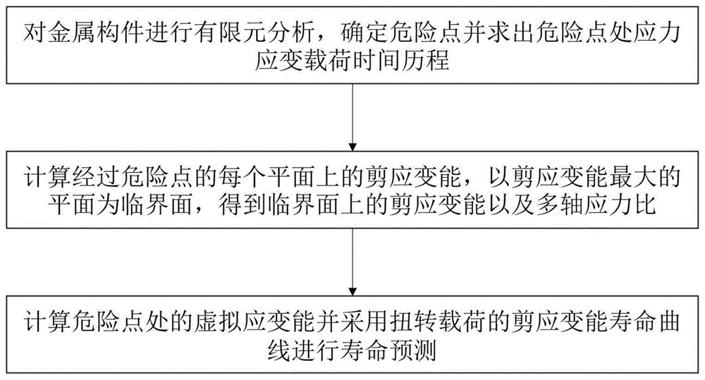
As shown in fig. 1, a method for predicting a multi-axial fatigue life of a metal material based on virtual strain energy disclosed in an embodiment of the present invention includes the following main steps:
(1) and carrying out finite element analysis on the metal member, determining a dangerous point and solving the stress-strain load time history at the dangerous point.
The method mainly comprises the following steps:
for a given external load, establishing a geometric model of the component by adopting three-dimensional modeling software, and importing finite element software;
carrying out grid division on the geometric model, and carrying out grid refinement on the vicinity of the fatigue danger point until the calculation result is converged;
giving material attributes to a finite element model, and selecting a linear elastic or elastic-plastic constitutive model according to whether the material has plastic strain in the fatigue test process;
adding boundary conditions to the finite element model, and simulating the load condition of the component in the real environment;
and finally, obtaining the stress-strain load time history at the dangerous point O by finite element analysis for subsequent calculation.
(2) And calculating the shear strain energy on each plane passing through the dangerous point, and taking the plane with the maximum shear strain energy as a critical plane to obtain the shear strain energy and the multi-axis stress ratio on the critical plane. The method mainly comprises the following steps:
set the metal member at time [0, T]The internal bearing load establishes a local cartesian coordinate system Oxyz at the fatigue danger point O, and an arbitrary plane Δ passing through the danger point O can be described by two direction vectors on the plane thereof and a normal vector of the plane. Specifically, a vector a is an intersection of the plane Δ and a plane Oxy in the coordinate system Oxyz, a vector b is a vector perpendicular to the a-axis on the plane Δ, and n is a normal vector of the plane Δ. The position relation of the vector n, a, b and the coordinate system Oxyz can be realized by three angles
It is shown that, among others,
is the included angle between the normal vector n of the direction of the plane delta and the x axis; theta is the included angle between the normal vector n and the z axis of the direction of the plane delta, and alpha is the included angle between any vector q and the vector a on the plane delta. The stress-strain load time history at the hazard point O can be represented by the following matrix:
in the formula, σx(t),σy(t),σz(t) is the normal stress component, τxy(t),τyz(t),τxz(t) is a shear stress component, εx(t),εy(t),εz(t) is a positive strain component, γxy(t),γyz(t),γxz(T) a shear strain component, T being [0, T]At any time within the interval.
Three unit vectors n, a, b describing the plane Δ are represented by coordinate transformation as:
an arbitrary unit vector q on plane Δ can be written as:
positive stress sigma at any anglen(t) shear stress τq(t) shear strain γq(t) can be written as:
σn(t)=nT[σ(t)]n
τq(t)=qT[σ(t)]n
γq(t)=2qT[ε(t)]n
mean value of positive stress σ on arbitrary planen,mIs defined as [0, T]Mean value of integral of positive stress within interval, positive stress amplitude σn,aDefinition by variance of normal stress
In the formula,
similarly, the shear stress, the mean value of the shear strain and the amplitude τ can be definedm,τa,γm,γa:
In the formula,
the shear strain energy Δ τ Δ γ is defined as the smallest rectangle of the component surrounding the hysteresis loop under the steady cycle, i.e. the product of the shear stress amplitude Δ τ and the shear strain amplitude Δ γ, the amplitude Δ τ being 2 τ ═ ya,Δγ=2γaIs thus
ΔτΔγ=4τa×γa
The multi-axial stress ratio ρ is defined as the maximum value of the positive stress σn,maxAnd the shear stress amplitude tauaThe ratio of (a) to (b), namely:
(3) and calculating virtual strain energy at the dangerous point and predicting the service life by adopting a shear strain energy service life curve of the torsional load. The virtual strain energy is the strain energy obtained by normalizing the shear strain energy in the service life curve of the shear strain energy under the uniaxial tension and compression load and the torsional load. The shear strain energy life curve under the uniaxial tension-compression load and the torsional load is determined in advance according to the uniaxial tension-compression and torsional fatigue test data of the material. The method specifically comprises the following steps:
respectively calculating shear strain energy on each fatigue data point critical surface under uniaxial tension-compression and torsional loads, drawing a shear strain energy-life curve end to end, and fitting to solve each parameter A of the shear strain energy-life curve under two load conditions1,B1,A3,B3。
And analyzing a shear strain energy-life curve of a typical ductile metal material in a uniaxial tension-compression and torsion state. The shear strain energy under two load conditions and the service life have a good log-log linear relationship, and the two curves are respectively subjected to power function fitting, so that the shear strain energy corresponding to the service life can be described.
Uniaxial tension-compression load
The virtual strain energy is obtained by normalizing the shear strain energy of different load paths, thereby calculating the fatigue life:
in the formula, the influence of different load paths is reflected by the multi-axis stress ratio ρ.
The detailed process of calculating the fatigue life based on the life curve under torsional load of the virtual strain energy can be seen in fig. 3.
The scheme of the invention is further verified by a specific experimental example. The material used in this example was 316L stainless steel produced by selective laser melting and tested for fatigue in a variety of load paths, namely uniaxial tension and compression, torsion, proportional and 90 ° non-proportional multi-axial loads. Firstly, finite element analysis is carried out on a test piece, a danger point is determined, and the stress-strain load time history [ sigma (t)) at the danger point is worked out],[ε(t)](ii) a Then solving shear strain energy delta tau delta gamma and multi-axis stress ratio rho on the critical surface through coordinate transformation; determining the parameter A of the model according to the uniaxial tension-compression and torsional fatigue test data of the material1,B1,A3,B3(ii) a Finally calculating the virtual strain energy W of the dangerous point under the load to be solvedVAnd solving for lifetime Nf. The detailed process is as follows:
s1: the test piece material adopted in the embodiment is additive manufacturing 316L steel, the length of the gauge length is 38mm, and the diameter of the gauge length is 12 mm. Uniaxial tension-compression, torsion, multiaxial proportional load and 90-degree non-proportional load tests without average stress and uniaxial tension-compression, multiaxial proportional load and 90-degree non-proportional load tests with average stress are carried out by using an MTS809 tension-torsion tester. The fatigue data of the uniaxial tension-compression and torsion test piece is used for determining the parameters of the model, the fatigue data of other load paths is used for verifying the correctness of the model, and the specific test data is shown in table 1, wherein the load ratio R is the ratio of the minimum value to the maximum value of the stress and is used for describing the magnitude of the average stress, and the phase angle phi is the phase difference between the positive stress and the shear stress and is used for describing the non-proportional degree.
TABLE 1316L Steel fatigue test results
The finite element analysis was performed using the finite element software Patran & Nastran. And establishing an overall coordinate system by taking the mass center of the test piece as an origin and the axis direction of the test piece as an x axis. Because the stress-strain state of each point on the surface of the gauge section of the smooth test piece is the same, cracks can be initiated from any position on the surface of the gauge section, and the fatigue danger point is not assumed to be a point with coordinates (0,6, 0).
The grid division adopts a method of firstly establishing two-dimensional shell units and then generating three-dimensional solid units by rotating and sweeping along the axis, local encryption is carried out on fatigue dangerous points, 20 units are divided by 1mm, and the finite element modeling result is shown in figure 5.
During the fatigue test, no plastic strain or negligible plastic strain is found, so the elastic modulus E is 190.8GPa and the poisson ratio v is 0.3 measured by the static test by using the linear elastic constitutive model.
In order to simulate the loading condition of the test piece on the testing machine, one end of the test piece is fixedly supported, and the MPC is established at the other end of the test piece and applied with load.
And finally, carrying out finite element calculation and deriving stress strain load time histories [ sigma (t) ], [ epsilon (t) ].
S2: programming by matlab software to three angles
From 0 DEG to 180 DEG, the step length is 1, the shear strain energy of each plane delta is respectively solved, the plane positioning critical plane with the maximum shear strain energy is found out, and the parameters required by the model are solved and listed in columns 3-7 of Table 2.
Table 2316L Steel data calculated using this model
S3: the shear strain energy DeltaDeltaGamma-lifetime N under the conditions of uniaxial tension and compression (numbers P-03 to P-12) and torsion (numbers P-21 to P-28) is plottedfThe curve, as shown in FIG. 4, is fitted with a power function using matlab fitting program or Excel fitting function to find A1=5.42,B1=-0.13,A3=3.03,B3=-0.06。
S4: according to the model
Solving the virtual strain energy value W under each load conditionVAnd calculating the lifetime Nf,eListed in columns 8 and 9 of Table 2, respectively. To facilitate comparison of the results, the results of the calculations and the results of the experiments are plotted in FIG. 6. As can be seen, 79% of the life prediction points are within the 2-fold error band, 93% of the life prediction points are within the 3-fold error band, and fatigue occurs on various load pathsThe service life prediction obtains a better prediction effect.
Based on the same inventive concept, the metallic material multi-axial fatigue life prediction system based on the virtual strain energy provided by the embodiment of the invention, as shown in fig. 7, comprises an input module, a processing module and an output module, wherein the input module is used for inputting a geometric model of a metallic component and an external load; the output module is used for displaying the predicted service life of the metal component under a given external load; the processing module comprises: the stress-strain calculation unit is used for carrying out finite element analysis on the metal component, determining a dangerous point and solving the stress-strain load time history at the dangerous point; the critical surface calculation unit is used for calculating the shear strain energy of each plane passing through the danger point, and obtaining the shear strain energy and the multi-axis stress ratio on the critical surface by taking the plane with the maximum shear strain energy as the critical surface; wherein the shear strain energy is defined as the product of shear stress amplitude and shear strain amplitude, and the multi-axial stress ratio is defined as the ratio of the maximum value of the normal stress on the critical surface to the shear stress amplitude; the prediction unit is used for calculating the virtual strain energy at the dangerous point and predicting the service life by adopting a shear strain energy service life curve of the torsional load; the virtual strain energy is the strain energy after normalization processing is carried out on the shear strain energy in the shear strain energy life curve under the uniaxial tension-compression load and the torsional load. Shear strain energy life curves under the uniaxial tension and compression load and the torsional load are generated by a power function fitting unit, the power function fitting unit is used for calculating the shear strain energy on the critical surface of each fatigue data point under the uniaxial tension and compression load and the torsional load respectively, the shear strain energy-life curves are drawn in an end-to-end connection mode, and the power functions are used for fitting and solving various parameters of the shear strain energy-life curves under the two load conditions respectively.
It can be clearly understood by those skilled in the art that, for convenience and simplicity of description, the specific working processes of the above-described units may refer to the corresponding processes in the foregoing method embodiments, and are not described herein again. The division of the unit is only one logical function division, and other division modes can be realized in practice, for example, a plurality of units can be combined or can be integrated into another system.
Based on the same inventive concept, an embodiment of the present invention provides a computer system, which includes a memory, a processor, and a computer program stored in the memory and executable on the processor, and when the computer program is loaded into the processor, the computer system implements the method for predicting the multi-axial fatigue life of a metal material based on virtual strain energy.
It will be understood by those skilled in the art that the technical solutions of the present invention may be embodied in the form of a software product, which is stored in a storage medium and includes instructions for causing a computer device (which may be a personal computer, a server, or a network device) to perform all or part of the steps of the method according to the embodiments of the present invention. The storage medium includes: various media capable of storing computer programs, such as a U disk, a removable hard disk, a read only memory ROM, a random access memory RAM, a magnetic disk, or an optical disk.
The foregoing is only a preferred embodiment of this invention and it should be noted that modifications can be made by those skilled in the art without departing from the principle of the invention and these modifications should also be considered as the protection scope of the invention.