CN1145773C - Process to produce nitrogen using double column plus auxiliary low pressure separation zone - Google Patents
Process to produce nitrogen using double column plus auxiliary low pressure separation zone Download PDFInfo
- Publication number
- CN1145773C CN1145773C CNB971171963A CN97117196A CN1145773C CN 1145773 C CN1145773 C CN 1145773C CN B971171963 A CNB971171963 A CN B971171963A CN 97117196 A CN97117196 A CN 97117196A CN 1145773 C CN1145773 C CN 1145773C
- Authority
- CN
- China
- Prior art keywords
- pressure
- tower
- stream
- low pressure
- reboiler
- Prior art date
- Legal status (The legal status is an assumption and is not a legal conclusion. Google has not performed a legal analysis and makes no representation as to the accuracy of the status listed.)
- Expired - Fee Related
Links
Images


Classifications
-
- F—MECHANICAL ENGINEERING; LIGHTING; HEATING; WEAPONS; BLASTING
- F25—REFRIGERATION OR COOLING; COMBINED HEATING AND REFRIGERATION SYSTEMS; HEAT PUMP SYSTEMS; MANUFACTURE OR STORAGE OF ICE; LIQUEFACTION SOLIDIFICATION OF GASES
- F25J—LIQUEFACTION, SOLIDIFICATION OR SEPARATION OF GASES OR GASEOUS OR LIQUEFIED GASEOUS MIXTURES BY PRESSURE AND COLD TREATMENT OR BY BRINGING THEM INTO THE SUPERCRITICAL STATE
- F25J1/00—Processes or apparatus for liquefying or solidifying gases or gaseous mixtures
-
- F—MECHANICAL ENGINEERING; LIGHTING; HEATING; WEAPONS; BLASTING
- F25—REFRIGERATION OR COOLING; COMBINED HEATING AND REFRIGERATION SYSTEMS; HEAT PUMP SYSTEMS; MANUFACTURE OR STORAGE OF ICE; LIQUEFACTION SOLIDIFICATION OF GASES
- F25J—LIQUEFACTION, SOLIDIFICATION OR SEPARATION OF GASES OR GASEOUS OR LIQUEFIED GASEOUS MIXTURES BY PRESSURE AND COLD TREATMENT OR BY BRINGING THEM INTO THE SUPERCRITICAL STATE
- F25J3/00—Processes or apparatus for separating the constituents of gaseous or liquefied gaseous mixtures involving the use of liquefaction or solidification
- F25J3/02—Processes or apparatus for separating the constituents of gaseous or liquefied gaseous mixtures involving the use of liquefaction or solidification by rectification, i.e. by continuous interchange of heat and material between a vapour stream and a liquid stream
- F25J3/04—Processes or apparatus for separating the constituents of gaseous or liquefied gaseous mixtures involving the use of liquefaction or solidification by rectification, i.e. by continuous interchange of heat and material between a vapour stream and a liquid stream for air
- F25J3/04763—Start-up or control of the process; Details of the apparatus used
- F25J3/04866—Construction and layout of air fractionation equipments, e.g. valves, machines
- F25J3/04872—Vertical layout of cold equipments within in the cold box, e.g. columns, heat exchangers etc.
- F25J3/04884—Arrangement of reboiler-condensers
-
- F—MECHANICAL ENGINEERING; LIGHTING; HEATING; WEAPONS; BLASTING
- F25—REFRIGERATION OR COOLING; COMBINED HEATING AND REFRIGERATION SYSTEMS; HEAT PUMP SYSTEMS; MANUFACTURE OR STORAGE OF ICE; LIQUEFACTION SOLIDIFICATION OF GASES
- F25J—LIQUEFACTION, SOLIDIFICATION OR SEPARATION OF GASES OR GASEOUS OR LIQUEFIED GASEOUS MIXTURES BY PRESSURE AND COLD TREATMENT OR BY BRINGING THEM INTO THE SUPERCRITICAL STATE
- F25J3/00—Processes or apparatus for separating the constituents of gaseous or liquefied gaseous mixtures involving the use of liquefaction or solidification
- F25J3/02—Processes or apparatus for separating the constituents of gaseous or liquefied gaseous mixtures involving the use of liquefaction or solidification by rectification, i.e. by continuous interchange of heat and material between a vapour stream and a liquid stream
- F25J3/04—Processes or apparatus for separating the constituents of gaseous or liquefied gaseous mixtures involving the use of liquefaction or solidification by rectification, i.e. by continuous interchange of heat and material between a vapour stream and a liquid stream for air
- F25J3/04248—Generation of cold for compensating heat leaks or liquid production, e.g. by Joule-Thompson expansion
- F25J3/04284—Generation of cold for compensating heat leaks or liquid production, e.g. by Joule-Thompson expansion using internal refrigeration by open-loop gas work expansion, e.g. of intermediate or oxygen enriched (waste-)streams
- F25J3/0429—Generation of cold for compensating heat leaks or liquid production, e.g. by Joule-Thompson expansion using internal refrigeration by open-loop gas work expansion, e.g. of intermediate or oxygen enriched (waste-)streams of feed air, e.g. used as waste or product air or expanded into an auxiliary column
- F25J3/04303—Lachmann expansion, i.e. expanded into oxygen producing or low pressure column
-
- F—MECHANICAL ENGINEERING; LIGHTING; HEATING; WEAPONS; BLASTING
- F25—REFRIGERATION OR COOLING; COMBINED HEATING AND REFRIGERATION SYSTEMS; HEAT PUMP SYSTEMS; MANUFACTURE OR STORAGE OF ICE; LIQUEFACTION SOLIDIFICATION OF GASES
- F25J—LIQUEFACTION, SOLIDIFICATION OR SEPARATION OF GASES OR GASEOUS OR LIQUEFIED GASEOUS MIXTURES BY PRESSURE AND COLD TREATMENT OR BY BRINGING THEM INTO THE SUPERCRITICAL STATE
- F25J3/00—Processes or apparatus for separating the constituents of gaseous or liquefied gaseous mixtures involving the use of liquefaction or solidification
- F25J3/02—Processes or apparatus for separating the constituents of gaseous or liquefied gaseous mixtures involving the use of liquefaction or solidification by rectification, i.e. by continuous interchange of heat and material between a vapour stream and a liquid stream
- F25J3/04—Processes or apparatus for separating the constituents of gaseous or liquefied gaseous mixtures involving the use of liquefaction or solidification by rectification, i.e. by continuous interchange of heat and material between a vapour stream and a liquid stream for air
- F25J3/04406—Processes or apparatus for separating the constituents of gaseous or liquefied gaseous mixtures involving the use of liquefaction or solidification by rectification, i.e. by continuous interchange of heat and material between a vapour stream and a liquid stream for air using a dual pressure main column system
- F25J3/04424—Processes or apparatus for separating the constituents of gaseous or liquefied gaseous mixtures involving the use of liquefaction or solidification by rectification, i.e. by continuous interchange of heat and material between a vapour stream and a liquid stream for air using a dual pressure main column system without thermally coupled high and low pressure columns, i.e. a so-called split columns
-
- F—MECHANICAL ENGINEERING; LIGHTING; HEATING; WEAPONS; BLASTING
- F25—REFRIGERATION OR COOLING; COMBINED HEATING AND REFRIGERATION SYSTEMS; HEAT PUMP SYSTEMS; MANUFACTURE OR STORAGE OF ICE; LIQUEFACTION SOLIDIFICATION OF GASES
- F25J—LIQUEFACTION, SOLIDIFICATION OR SEPARATION OF GASES OR GASEOUS OR LIQUEFIED GASEOUS MIXTURES BY PRESSURE AND COLD TREATMENT OR BY BRINGING THEM INTO THE SUPERCRITICAL STATE
- F25J3/00—Processes or apparatus for separating the constituents of gaseous or liquefied gaseous mixtures involving the use of liquefaction or solidification
- F25J3/02—Processes or apparatus for separating the constituents of gaseous or liquefied gaseous mixtures involving the use of liquefaction or solidification by rectification, i.e. by continuous interchange of heat and material between a vapour stream and a liquid stream
- F25J3/04—Processes or apparatus for separating the constituents of gaseous or liquefied gaseous mixtures involving the use of liquefaction or solidification by rectification, i.e. by continuous interchange of heat and material between a vapour stream and a liquid stream for air
- F25J3/04406—Processes or apparatus for separating the constituents of gaseous or liquefied gaseous mixtures involving the use of liquefaction or solidification by rectification, i.e. by continuous interchange of heat and material between a vapour stream and a liquid stream for air using a dual pressure main column system
- F25J3/0443—A main column system not otherwise provided, e.g. a modified double column flowsheet
-
- F—MECHANICAL ENGINEERING; LIGHTING; HEATING; WEAPONS; BLASTING
- F25—REFRIGERATION OR COOLING; COMBINED HEATING AND REFRIGERATION SYSTEMS; HEAT PUMP SYSTEMS; MANUFACTURE OR STORAGE OF ICE; LIQUEFACTION SOLIDIFICATION OF GASES
- F25J—LIQUEFACTION, SOLIDIFICATION OR SEPARATION OF GASES OR GASEOUS OR LIQUEFIED GASEOUS MIXTURES BY PRESSURE AND COLD TREATMENT OR BY BRINGING THEM INTO THE SUPERCRITICAL STATE
- F25J3/00—Processes or apparatus for separating the constituents of gaseous or liquefied gaseous mixtures involving the use of liquefaction or solidification
- F25J3/02—Processes or apparatus for separating the constituents of gaseous or liquefied gaseous mixtures involving the use of liquefaction or solidification by rectification, i.e. by continuous interchange of heat and material between a vapour stream and a liquid stream
- F25J3/04—Processes or apparatus for separating the constituents of gaseous or liquefied gaseous mixtures involving the use of liquefaction or solidification by rectification, i.e. by continuous interchange of heat and material between a vapour stream and a liquid stream for air
- F25J3/04436—Processes or apparatus for separating the constituents of gaseous or liquefied gaseous mixtures involving the use of liquefaction or solidification by rectification, i.e. by continuous interchange of heat and material between a vapour stream and a liquid stream for air using at least a triple pressure main column system
- F25J3/04454—Processes or apparatus for separating the constituents of gaseous or liquefied gaseous mixtures involving the use of liquefaction or solidification by rectification, i.e. by continuous interchange of heat and material between a vapour stream and a liquid stream for air using at least a triple pressure main column system a main column system not otherwise provided, e.g. serially coupling of columns or more than three pressure levels
-
- F—MECHANICAL ENGINEERING; LIGHTING; HEATING; WEAPONS; BLASTING
- F25—REFRIGERATION OR COOLING; COMBINED HEATING AND REFRIGERATION SYSTEMS; HEAT PUMP SYSTEMS; MANUFACTURE OR STORAGE OF ICE; LIQUEFACTION SOLIDIFICATION OF GASES
- F25J—LIQUEFACTION, SOLIDIFICATION OR SEPARATION OF GASES OR GASEOUS OR LIQUEFIED GASEOUS MIXTURES BY PRESSURE AND COLD TREATMENT OR BY BRINGING THEM INTO THE SUPERCRITICAL STATE
- F25J2200/00—Processes or apparatus using separation by rectification
- F25J2200/20—Processes or apparatus using separation by rectification in an elevated pressure multiple column system wherein the lowest pressure column is at a pressure well above the minimum pressure needed to overcome pressure drop to reject the products to atmosphere
-
- F—MECHANICAL ENGINEERING; LIGHTING; HEATING; WEAPONS; BLASTING
- F25—REFRIGERATION OR COOLING; COMBINED HEATING AND REFRIGERATION SYSTEMS; HEAT PUMP SYSTEMS; MANUFACTURE OR STORAGE OF ICE; LIQUEFACTION SOLIDIFICATION OF GASES
- F25J—LIQUEFACTION, SOLIDIFICATION OR SEPARATION OF GASES OR GASEOUS OR LIQUEFIED GASEOUS MIXTURES BY PRESSURE AND COLD TREATMENT OR BY BRINGING THEM INTO THE SUPERCRITICAL STATE
- F25J2200/00—Processes or apparatus using separation by rectification
- F25J2200/32—Processes or apparatus using separation by rectification using a side column fed by a stream from the high pressure column
-
- F—MECHANICAL ENGINEERING; LIGHTING; HEATING; WEAPONS; BLASTING
- F25—REFRIGERATION OR COOLING; COMBINED HEATING AND REFRIGERATION SYSTEMS; HEAT PUMP SYSTEMS; MANUFACTURE OR STORAGE OF ICE; LIQUEFACTION SOLIDIFICATION OF GASES
- F25J—LIQUEFACTION, SOLIDIFICATION OR SEPARATION OF GASES OR GASEOUS OR LIQUEFIED GASEOUS MIXTURES BY PRESSURE AND COLD TREATMENT OR BY BRINGING THEM INTO THE SUPERCRITICAL STATE
- F25J2200/00—Processes or apparatus using separation by rectification
- F25J2200/34—Processes or apparatus using separation by rectification using a side column fed by a stream from the low pressure column
-
- F—MECHANICAL ENGINEERING; LIGHTING; HEATING; WEAPONS; BLASTING
- F25—REFRIGERATION OR COOLING; COMBINED HEATING AND REFRIGERATION SYSTEMS; HEAT PUMP SYSTEMS; MANUFACTURE OR STORAGE OF ICE; LIQUEFACTION SOLIDIFICATION OF GASES
- F25J—LIQUEFACTION, SOLIDIFICATION OR SEPARATION OF GASES OR GASEOUS OR LIQUEFIED GASEOUS MIXTURES BY PRESSURE AND COLD TREATMENT OR BY BRINGING THEM INTO THE SUPERCRITICAL STATE
- F25J2200/00—Processes or apparatus using separation by rectification
- F25J2200/50—Processes or apparatus using separation by rectification using multiple (re-)boiler-condensers at different heights of the column
- F25J2200/54—Processes or apparatus using separation by rectification using multiple (re-)boiler-condensers at different heights of the column in the low pressure column of a double pressure main column system
-
- F—MECHANICAL ENGINEERING; LIGHTING; HEATING; WEAPONS; BLASTING
- F25—REFRIGERATION OR COOLING; COMBINED HEATING AND REFRIGERATION SYSTEMS; HEAT PUMP SYSTEMS; MANUFACTURE OR STORAGE OF ICE; LIQUEFACTION SOLIDIFICATION OF GASES
- F25J—LIQUEFACTION, SOLIDIFICATION OR SEPARATION OF GASES OR GASEOUS OR LIQUEFIED GASEOUS MIXTURES BY PRESSURE AND COLD TREATMENT OR BY BRINGING THEM INTO THE SUPERCRITICAL STATE
- F25J2200/00—Processes or apparatus using separation by rectification
- F25J2200/90—Details relating to column internals, e.g. structured packing, gas or liquid distribution
-
- F—MECHANICAL ENGINEERING; LIGHTING; HEATING; WEAPONS; BLASTING
- F25—REFRIGERATION OR COOLING; COMBINED HEATING AND REFRIGERATION SYSTEMS; HEAT PUMP SYSTEMS; MANUFACTURE OR STORAGE OF ICE; LIQUEFACTION SOLIDIFICATION OF GASES
- F25J—LIQUEFACTION, SOLIDIFICATION OR SEPARATION OF GASES OR GASEOUS OR LIQUEFIED GASEOUS MIXTURES BY PRESSURE AND COLD TREATMENT OR BY BRINGING THEM INTO THE SUPERCRITICAL STATE
- F25J2215/00—Processes characterised by the type or other details of the product stream
- F25J2215/42—Nitrogen or special cases, e.g. multiple or low purity N2
- F25J2215/44—Ultra high purity nitrogen, i.e. generally less than 1 ppb impurities
-
- F—MECHANICAL ENGINEERING; LIGHTING; HEATING; WEAPONS; BLASTING
- F25—REFRIGERATION OR COOLING; COMBINED HEATING AND REFRIGERATION SYSTEMS; HEAT PUMP SYSTEMS; MANUFACTURE OR STORAGE OF ICE; LIQUEFACTION SOLIDIFICATION OF GASES
- F25J—LIQUEFACTION, SOLIDIFICATION OR SEPARATION OF GASES OR GASEOUS OR LIQUEFIED GASEOUS MIXTURES BY PRESSURE AND COLD TREATMENT OR BY BRINGING THEM INTO THE SUPERCRITICAL STATE
- F25J2215/00—Processes characterised by the type or other details of the product stream
- F25J2215/50—Oxygen or special cases, e.g. isotope-mixtures or low purity O2
- F25J2215/56—Ultra high purity oxygen, i.e. generally more than 99,9% O2
-
- F—MECHANICAL ENGINEERING; LIGHTING; HEATING; WEAPONS; BLASTING
- F25—REFRIGERATION OR COOLING; COMBINED HEATING AND REFRIGERATION SYSTEMS; HEAT PUMP SYSTEMS; MANUFACTURE OR STORAGE OF ICE; LIQUEFACTION SOLIDIFICATION OF GASES
- F25J—LIQUEFACTION, SOLIDIFICATION OR SEPARATION OF GASES OR GASEOUS OR LIQUEFIED GASEOUS MIXTURES BY PRESSURE AND COLD TREATMENT OR BY BRINGING THEM INTO THE SUPERCRITICAL STATE
- F25J2235/00—Processes or apparatus involving steps for increasing the pressure or for conveying of liquid process streams
- F25J2235/42—Processes or apparatus involving steps for increasing the pressure or for conveying of liquid process streams the fluid being nitrogen
-
- F—MECHANICAL ENGINEERING; LIGHTING; HEATING; WEAPONS; BLASTING
- F25—REFRIGERATION OR COOLING; COMBINED HEATING AND REFRIGERATION SYSTEMS; HEAT PUMP SYSTEMS; MANUFACTURE OR STORAGE OF ICE; LIQUEFACTION SOLIDIFICATION OF GASES
- F25J—LIQUEFACTION, SOLIDIFICATION OR SEPARATION OF GASES OR GASEOUS OR LIQUEFIED GASEOUS MIXTURES BY PRESSURE AND COLD TREATMENT OR BY BRINGING THEM INTO THE SUPERCRITICAL STATE
- F25J2245/00—Processes or apparatus involving steps for recycling of process streams
- F25J2245/42—Processes or apparatus involving steps for recycling of process streams the recycled stream being nitrogen
-
- F—MECHANICAL ENGINEERING; LIGHTING; HEATING; WEAPONS; BLASTING
- F25—REFRIGERATION OR COOLING; COMBINED HEATING AND REFRIGERATION SYSTEMS; HEAT PUMP SYSTEMS; MANUFACTURE OR STORAGE OF ICE; LIQUEFACTION SOLIDIFICATION OF GASES
- F25J—LIQUEFACTION, SOLIDIFICATION OR SEPARATION OF GASES OR GASEOUS OR LIQUEFIED GASEOUS MIXTURES BY PRESSURE AND COLD TREATMENT OR BY BRINGING THEM INTO THE SUPERCRITICAL STATE
- F25J2250/00—Details related to the use of reboiler-condensers
- F25J2250/20—Boiler-condenser with multiple exchanger cores in parallel or with multiple re-boiling or condensing streams
Landscapes
- Engineering & Computer Science (AREA)
- Physics & Mathematics (AREA)
- Mechanical Engineering (AREA)
- Thermal Sciences (AREA)
- General Engineering & Computer Science (AREA)
- Separation By Low-Temperature Treatments (AREA)
Abstract
A process is set forth for the cryogenic distillation of an air feed to produce nitrogen, particularly high pressure nitrogen of various purity, varying from low purity (up to 98% nitrogen) to ultra-high purity (less than 1 part per billion of oxygen). The nitrogen may be produced at two different pressures and two different purities. The process uses an auxiliary low pressure separation zone in addition to the conventional high pressure column and low pressure column. The auxiliary low pressure separation zone, which is operated at the same pressure as the low pressure column and which is heat integrated with the top of the high pressure column by means of its bottom reboiler/condenser, pretreats the crude liquid oxygen from the bottom of the high pressure column.
Description
Technical field
The present invention relates to a kind of method of low temperature air separating feeding.Term used herein " air feed " generally is meant atmospheric air but also comprises any admixture of gas that has the nitrogen of oxygen at least.
Background technology
Target market of the present invention is the elevated pressure nitrogen of various purity, changes to ultra-high purity (less than one of 1,000,000,000 parts oxygen) from low-purity (until 98% nitrogen), for example has been used in the nitrogen of chemistry and electronics industry all departments.Some application may need to supply the nitrogen with two kinds of pressure and two kinds of purity.In some other method, may need all nitrogen products of high-purity and high pressure.An object of the present invention is to design a kind of effective low temperature circulation, make its easy adaptation can satisfy all these needs.
In producing nitrogen technology some being arranged is known methods.These methods can by the quantity of destilling tower classify the circulation of for example single tower, band prefractionation device or aftercut device single tower, double tower circulation and comprise the circulation of two above destilling towers.
Traditional single tower nitrogen cycle is at United States Patent (USP) 4,222, the people is learnt in 756.Carburetted air is fed to the bottom of a rectifier, it is separated into cat head at this place and distillates vaporization nitrogen and an end liquid, and this carburetted air is by step-down, and forms the backflow that needs by the indirect heat exchange that distillates steam with cat head and seethed with excitement at cat head.To discharge as waste stream from the boil oxygen-rich steam of device/condenser of top-heavy.
The advantage of single post nitrogenous generator is that it is simple and cost is low.One big advantage of this circulation is that limited nitrogen reclaims.Other various types of single-column nitrogenous generators are then recommended to be used for increasing nitrogen and to reclaim.Press United States Patent (USP) 4,594,085th, at the bottom of tower, use an auxiliary reboiler, this tower is formed an additional liquid air feeding with respect to air vaporization part end liquid.At United States Patent (USP) 5,037, make the people learn a kind of similar denseization circulation in 462, this circulation only has an air compander.At United States Patent (USP) 4,662, make in 916 the people learn a kind of single tower circulation with two reboilers.And, another single tower circulation is then described in 002 at United States Patent (USP) 4,966, a part of rich nitrogenous wastes stream is compressed and recycles and turns back in this tower with further increase nitrogen recovery in this circulation.Similar situation at United States Patent (USP) 5,385, is back to this tower with a part of oxygen enrichment waste stream cold compression expansion and with the feeding air re-circulation in 024.
By additional second distilling apparatus the nitrogen of one single Tower System being reclaimed improves a lot.This device can be a full destilling tower or one small-sized pre-/the aftercut device, make flash distillation plant or only comprise the small-sized tower of several progression.At United States Patent (USP) 4,604, make the people learn a kind of circulation that single tower has a prefractionation device that comprises in 117, the separated formation of some feeding air is to the new feeding of this king-tower in this circulation.At United States Patent (USP) 4,927, make the people learn that a kind of nitrogen circulates in 441, this circulation has the top that an aftercut device is installed in rectifier, and liquid is separated at this place even more oxygen-rich liquid and has the vaporization logistics of similar constituent of air at the bottom of the oxygen enrichment.This synthesis of air stream is recycled to rectifier, produces greatly improved product and reclaim and cycle efficieny.Equally, under different pressure, use twice vaporization of two reboilers oxygen-rich liquid can further improve cycle efficieny.
At United States Patent (USP) 4,222, make in 756 the people learn some traditional product nitrogen double towers circulations.In this patent, make the people learn that this novel distillation structure comprises and has the double tower of an additional reboiler/condenser at the top, forms this lower pressure column by this oxygen enrichment refuse liquid of vaporizing and refluxes.Freezing is to produce by the nitrogen of expansion from this high-pressure tower.
By BP 1,215,377 and United States Patent (USP) 4,453,957 make the people learn a kind of similar distillation structure (having freezing various expanding liquid).At United States Patent (USP) 4,617, use in 036 a side reboiler/condenser to substitute heat exchanger on the lower pressure column top.At United States Patent (USP) 5,006, make in 139 the people learn a kind of double tower circulation, reboiler in the middle of this circulates in and is provided with in the lower pressure column.At United States Patent (USP) 5,129, a kind of circulation of producing middle pressure nitrogen and producing oxygen and argon is simultaneously described in 932.
It is the single tower nitrogenous generator of standard (this structure is also referred to as classification tower circulation) of two series connection that United States Patent (USP) 4,439, the 220 double tower elevated pressure nitrogen methods that the people is learnt can be considered as.United States Patent (USP) 4,448,595 what be different from classification tower circulation is that this lower pressure column additionally is equipped with a reboiler.At United States Patent (USP) 5,098, also be shown with another modification of this classification tower circulation in 457, in this circulation, will be pumped back to high-pressure tower, with the recovery of increase high pressure product from the nitrogen liquid product at lower pressure column top.
United States Patent (USP) 5,069 has been described a kind of three towers circulation of producing nitrogen in 699, in this circulation except having one also to use an extra-lnigh tension destilling tower to increase nitrogen output having the double tower system of two reboilers.At United States Patent (USP) 5,402, make in 647 the people learn that another produces the three-tower system of a large amount of elevated pressure nitrogen.In the present invention, this additional tower is to work under a certain intermediate pressure of high-pressure tower and lower pressure column being equivalent to.
The United States Patent (USP) 5,231,837 of Ha Shi (Ha) makes the people learn a kind of air separation circulation, and wherein the top of high-pressure tower and lower pressure column bottom and medium pressure column bottom are thermal communications.This medium pressure column will be processed into a condensation top portion distillate and a bottom liquid fractionation from the original liquid oxygen of high-pressure tower bottom, and these liquid fractionations then all are fed in the lower pressure column.
The nitrogen cycle of all prior arts all has following shortcoming: to reclaim elevated pressure nitrogen be limited but also can not increase by Tower System.
Summary of the invention
The present invention is a kind of method, and this method is used for cryogenic separation one air feed to produce nitrogen, particularly produces the elevated pressure nitrogen of various purity, changes to ultra-high purity (less than one of 1,000,000,000 parts oxygen) from low-purity (until 98% nitrogen).This method can be produced nitrogen under two different pressure and two kinds of different purity.This method is also used an auxiliary low pressure Disengagement zone except using conventional high-tension tower and lower pressure column.This auxiliary low pressure Disengagement zone is to work under the pressure of lower pressure column being equivalent to, and makes itself and high-pressure tower top thermal communication with its bottom reboiler/condenser, and this auxiliary low pressure Disengagement zone is to the original liquid oxygen roughing bottom this high-pressure tower.
Description of drawings
Fig. 1 is the schematic diagram of a general embodiment of the present invention.
Fig. 2 is the schematic diagram of second general embodiment of the present invention.
Fig. 3 is the schematic diagram of the 3rd general embodiment of the present invention.
Fig. 4 is the schematic diagram of the 4th general embodiment of the present invention.
Fig. 5 is the schematic diagram of the 5th general embodiment of the present invention.
Fig. 6 is the schematic diagram of the 6th general embodiment of the present invention.
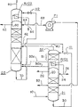
Fig. 7 be the embodiment schematic view illustrating of Fig. 1 between some towers of the present invention and/or Disengagement zone further combined with example.
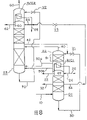
Fig. 8 be second embodiment schematic view illustrating of Fig. 1 between some towers of the present invention and/or Disengagement zone second further combined with example.
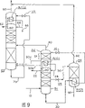
How Fig. 9 can produce the example that tower combines with a liquid oxygen for the 3rd embodiment schematic view illustrating the present invention of Fig. 1.
How Figure 10 can produce second example that tower combines with a liquid oxygen for the 4th embodiment schematic view illustrating the present invention of Fig. 1.
How Figure 11 can produce the 3rd example that tower combines with a liquid oxygen for the 5th embodiment schematic view illustrating the present invention of Fig. 1.
How Figure 12 can freezingly expand the example that device combines with a main heat exchanger, some auxiliary cooling heat exchangers and one for first embodiment schematic view illustrating different embodiments of the invention of Fig. 1.
The specific embodiment
The present invention is a kind of method, and this method is that an air feed low temperature distillation is produced nitrogen.This method is used a distillation column system, and this system comprises at least one high-pressure tower, a lower pressure column and an auxiliary low pressure Disengagement zone.This Disengagement zone comprises at least one reboiler/condenser again at its bottom and a distilling period that is positioned at above this reboiler/condenser in many examples.
By its broadest embodiment and consult any or all accompanying drawing 1 to 12, method of the present invention comprises:
(a) portion of air feeding at least [10] is fed to the bottom of this high-pressure tower [D1];
(b) extract a rich nitrogen overhead [20] from this high-pressure tower top, collect first part [22] as an elevated pressure nitrogen product, in second part of first reboiler/condenser [R/C1] condensation that is positioned at bottom, this auxiliary low pressure Disengagement zone [D2], and at least one part [24] in this condensation second portion is fed to a certain upper position in this high-pressure tower as backflow;
(c) extract an original liquid oxygen stream [30] from this high-pressure tower bottom, at least its first part is reduced pressure [through valve V1], and described first is fed to the top of this auxiliary low pressure Disengagement zone;
(d) extract an original nitrogen overhead [40] from this auxiliary low pressure Disengagement zone, and it directly is fed to this lower pressure column [D3] as a steam, wherein this auxiliary low pressure Disengagement zone is to be equivalent under the pressure of lower pressure column, adds that work falls in predictable pressure between this auxiliary low pressure Disengagement zone and this lower pressure column;
(e) a certain lower position from this auxiliary low pressure Disengagement zone extracts one or more oxygen-rich stream [50a, 50b] that is steam and/or liquid state, and,
(i) its any part directly is fed to this lower pressure column; And/or
(ii) its any vapor portion is discharged as a waste stream; And/or
(iii) by under low pressure at least partly its any liquid partly being vaporized with respect to indirect heat exchange from the 3rd portion's separation nitrogen-enriching overhead at this high-pressure tower top;
(f) extract a rich nitrogen overhead [60] from this lower pressure column top, will be at least together initial portion collects as a low pressure nitrogen product, at this moment or directly as a steam [62; Among Fig. 6 60] and/or as a liquid [except Fig. 6 66], this is to carry out after second reboiler/condenser [R/C2 except Fig. 6] that is positioned at this lower pressure column top is to its condensation; With
(g) extract a stream of oxygen-enriched liquid [70] from this lower pressure column bottom.
A key property of the present invention is this auxiliary low pressure Disengagement zone, and this Disengagement zone can comprise a single reboiler/condenser or a destilling tower that has a reboiler/condenser in its bottom.Available is that this Disengagement zone can comprise a plurality of reboilers and a plurality of destilling tower.This Disengagement zone is a thermal communication with its bottom reboiler/condenser and this high-pressure tower top.This Disengagement zone can be controlled this method preferably, and is providing selection scheme more flexible arrangement to be arranged aspect making the primary low tower and this high-pressure tower separating by the natural law.
Just as top (d) go on foot pointedly, this Disengagement zone is to be equivalent under the pressure of lower pressure column, adds that work falls in predictable pressure between this auxiliary low pressure Disengagement zone and this lower pressure column.Learn that unexpectedly in the possible working pressure range between high-pressure tower pressure and lower pressure column pressure, this is exactly best operating pressure to the Disengagement zone.And this also makes the technological process that exchanges between Disengagement zone and the lower pressure column comparatively simple and be easy to flow.
In most of embodiment of the present invention, except that Fig. 6 referring to all accompanying drawings:
(i) (f) step also is included in and is positioned at least remainder separation nitrogen-enriching overhead of this lower pressure column top second reboiler/condenser [R/C2] condensation from this lower pressure column, and the general wherein at least first [64] be fed to a certain upper position in this lower pressure column as backflow;
(ii) (g) step also comprises stream of oxygen-enriched liquid [70] decompression [through valve V2], it is being positioned at second reboiler/condenser [R/C2] vaporization at this lower pressure column top, and the logistics [80] of should vaporizing is discharged as a waste stream; With
(iii) the whole rich nitrogen overhead [20] that will extract from this high-pressure tower top is by coming condensation with respect to the vaporization oxygen-rich liquid indirect heat exchange bottom this auxiliary low pressure Disengagement zone.Except the part [22] that is extracted as the elevated pressure nitrogen product.(the United States Patent (USP) 5 that this and Ha Shi were discussed in the past, 231,837 differences, a part is also vaporized and condensation with respect to the oxygen-rich liquid bottom this lower pressure column from the distillate at this high-pressure tower top in this patent, in the Ha Shi patent, the top of this high-pressure tower and Ha Shi medium pressure column bottom and Ha Shi lower pressure column bottom both are thermal communications.Therefore, this feeding air pressure must be higher than the Ha Shi patent that causes energy demand to increase).
Equally in most of embodiment of the present invention, and referring to the institute's drawings attached that removes Fig. 5:
(i) wherein at least one is extracted one or more oxygen-rich stream that is extracted during (e) step from this auxiliary low pressure Disengagement zone, is local steam condition this moment at least; With
(ii) in (d) step, more properly be fed on a certain centre position of lower pressure column from the original nitrogen overhead [40] of this auxiliary low pressure Disengagement zone.
In a general embodiment of the present invention, and especially referring to Fig. 1:
(i) this auxiliary low pressure Disengagement zone also comprises a distilling period [S1] that is positioned at this first reboiler/condenser [R/C1] top; With
(ii) (e) step more properly comprises in this auxiliary low pressure Disengagement zone between this distilling period and this first reboiler/condenser a certain position and extracts first oxygen-rich steam and flow [50a], extract second stream of oxygen-enriched liquid [50b] from the bottom of this auxiliary low pressure Disengagement zone, and this first and second oxygen-rich stream is fed to the bottom of this lower pressure column.
In Fig. 1, for the distilling period [S1] of Disengagement zone, have ten or still less progression (or a packed height is equivalent to ten or progression still less) generally be enough.Equally in Fig. 1, the purity of low pressure nitrogen product [62] can equal, be lower than or even be higher than the purity of elevated pressure nitrogen product [22], this depends on people's needs.The purity level that this logistics is reached want must be provided with suitable progression or packed height to this lower pressure column.
In second general embodiment of the present invention, and especially referring to Fig. 2:
(i) (e) step more properly comprises and extracts single oxygen-rich steam stream [50a] from a certain centre position of this auxiliary low pressure Disengagement zone, and it is discharged as a waste stream;
(ii) this optional land used in auxiliary low pressure Disengagement zone also comprises a distilling period [S1] that is positioned at this first reboiler/condenser [R/C1] top, the single oxygen-rich steam stream [50a] that be extracted in (e) step this moment more properly in this auxiliary low pressure Disengagement zone between this distilling period and this first reboiler/condenser a certain position be extracted; With
(iii) optional land used also comprises the bottom that wherein second part [50b] of this single oxygen-rich steam stream is fed to this lower pressure column (e) step.
In Fig. 2,, (e) that discussed above selecting do not accomplish that the distilling period shown in this lower pressure column bottom may be unwanted among Fig. 2 at that time if going on foot in (iii).
In the 3rd general embodiment of the present invention, and especially referring to Fig. 3:
(i) this auxiliary low pressure Disengagement zone also comprises a distilling period [S1] that is positioned at this first reboiler/condenser [R/C1] top, except also comprising first auxiliary reboiler/condenser [R/C1a];
(ii) (b) step also comprises three part [23] the rich nitrogen overhead of condensation from this high-pressure tower top in this first auxiliary reboiler/condenser [R/C1a].And with this condensation third part wherein at least first part be fed to a certain upper position in this high-pressure tower as backflow; With
(iii) (e) goes on foot more properly to comprise from this a certain position, auxiliary low pressure Disengagement zone between this distilling period and this first reboiler/condenser [R/C1] and extracts first oxygen-rich stream [50a], and it is fed to this lower pressure column bottom, extract second stream of oxygen-enriched liquid [50b] from this bottom, auxiliary low pressure Disengagement zone, to its decompression [through valve V3], in this first auxiliary reboiler/condenser, make its vaporization, and the logistics [52] of should vaporizing is discharged as a waste stream.
By the 4th general embodiment of the present invention, and especially referring to Fig. 4:
(i) this auxiliary low pressure Disengagement zone also comprises first distilling period [S1] that is positioned at this first reboiler/condenser [R/C1] top, be positioned at second distilling period [S2] of this first reboiler/condenser [R/C1] below and be positioned at first auxiliary reboiler/condenser [R/C1a] of this after-fractionating section below.
(ii) (e) step more properly comprises from this after-fractionating section and this first and assists between the reboiler/condenser [R/C1a] in this auxiliary low pressure Disengagement zone a certain position to extract single oxygen-rich stream [50a], and it is fed to the bottom of this lower pressure column; With
(iii) with the condensation in this first auxiliary reboiler/condenser [R/C1a] of second part [12] of this air feed; And it is fed on a certain centre position of this high-pressure tower as backflow.
In Fig. 4, use the irreversibility that two reboiler/condenser replace one of them the minimizing flow process in this Disengagement zone.All condensations in addition of any suitable fluid in these reboiler/condenser.For example can be with a part of elevated pressure nitrogen overhead [20] supercharging, then condensation in this first auxiliary reboiler/condenser [R/C1a], or whole or local this air stream [12] that substitutes.
By the 5th general embodiment of the present invention, and especially referring to Fig. 5:
(i) this auxiliary low pressure Disengagement zone also comprises first auxiliary reboiler/condenser [R/C1a];
(ii) (b) step also comprises third part [23] the rich nitrogen overhead of condensation from this high-pressure tower top in this first auxiliary reboiler/condenser [R/C1a], and with this condensation third part wherein at least first part be fed to a certain upper position in this high-pressure tower as backflow;
(iii), will be fed to the bottom of this lower pressure column definitely from the original nitrogen overhead [40] of this auxiliary low pressure Disengagement zone in (d) step; With
(iv) (e) step more properly comprises from this bottom, auxiliary low pressure Disengagement zone extraction single stream of oxygen-enriched liquid [50a], to its decompression [through valve V3], in this first auxiliary reboiler/condenser [R/C1a] to its partial vaporization, the logistics of should vaporizing [52] is discharged as a waste stream, to raffinate part [54] decompression [through valve V4], and merge through this raffinate part and stream of oxygen-enriched liquid [70] from this lower pressure column bottom.
By the 6th general embodiment of the present invention, and especially referring to Fig. 6:
(i) this auxiliary low pressure Disengagement zone also comprises a distilling period that is positioned at this first reboiler/condenser [R/C1] top;
(ii) (b) step also comprises three part [23] the rich nitrogen overhead of condensation from this high-pressure tower top in second auxiliary reboiler/condenser [R/C2a], wherein first part [23a] of this condensation third part is fed to a certain upper position in this high-pressure tower as backflow, to wherein second part [23b] decompression [through valve V2], and wherein this second portion is fed to a certain upper position in this lower pressure column as backflow;
(iii) (e) step more properly comprises in this auxiliary low pressure Disengagement zone between this distilling period and this first reboiler/condenser a certain position and extracts first oxygen-rich stream [50a], and with its be fed to this lower pressure column the bottom ' with
(iv) (g) step also comprises stream of oxygen-enriched liquid [70] decompression [through valve V3], and to its vaporization, and the logistics [80] of should vaporizing is discharged as a waste stream in this second auxiliary reboiler/condenser [R/C2a].
In Fig. 6 also might with from the rich nitrogen overhead of whole third parts [23] at top high-pressure tower top of being discussed in (ii) as refluxing or being fed to this high-pressure tower or being fed to this lower pressure column.
Should be noted that to the above-mentioned general embodiment between these towers and/or the Disengagement zone of the present invention further combined with have many may.Fig. 7 and 8 is as two examples that are used for Fig. 1 (shared logistics and device use the label that is same as Fig. 1).
Referring to Fig. 7:
(i) a certain centre position is extracted a part and is risen the nitrogen rich vapor [32] of this high-pressure tower as additional high-pressure nitrogen product in this high-pressure tower;
(ii) collect wherein second part [26] from the rich nitrogen overhead of this condensation second portion of this high-pressure tower as additional high-pressure nitrogen product;
(iii) extract the oxygen-rich liquid [42] of this lower pressure column of part decline, and it is fed to the top of this auxiliary low pressure Disengagement zone from a certain centre position of this lower pressure column; With
(iv) in (f) step, will from this lower pressure column wherein the rich nitrogen overhead of this condensation of second part [68] pump and it is fed to a certain centre position in this high-pressure tower to a certain high pressure [in pump P1].
In Fig. 7, (iv) increase recovery to the liquid nitrogen of this high-pressure tower recirculation [68] from the elevated pressure nitrogen product [22,26,32] of this high-pressure tower by above-mentioned.Equally in Fig. 7, (iii) further increase recovery to oxygen-rich liquid [42] recirculation of this Disengagement zone from the liquid elevated pressure nitrogen product [26] of this high-pressure tower by above-mentioned.
Fig. 8 is equal to Fig. 7, except being replaced by going on foot down by the top (iv) described step:
(iv) extract the rich nitrogen liquid [34] of this high-pressure tower of part decline,, and be fed to this lower pressure column its decompression [through valve V3] from a certain centre position of this high-pressure tower.
In Fig. 8, should be from being lower than a certain suitable height extract flow [34] at this high-pressure tower top, if particularly the purity of this low pressure nitrogen product [62,66] is lower than the purity of this elevated pressure nitrogen product [22,26,32].If these purity equate, just can be from this high-pressure tower top extract flow [34].
It should be appreciated that the present invention can be produced tower with a liquid oxygen combines to produce a ultra-high purity liquid oxygen product.Fig. 9,10 and 11 are three examples (shared logistics is used the identical label of Fig. 1 with device) that are used for Fig. 1.
Referring to Fig. 9:
(i) this distillation column system also comprises liquid oxygen production tower [D4], and this tower comprises the 3rd reboiler/condenser [R/C3] in its bottom;
(ii) extract a poor hydrocarbon stream [36],, and be fed to the top that this liquid oxygen is produced tower its decompression [through valve V4] from a certain centre position of this high-pressure tower;
(iii) to original liquid oxygen stream [30] first decompression, and it is fed to before this top, auxiliary low pressure Disengagement zone, with described first auxiliary cooling the 3rd reboiler/condenser [R/C3] in from this high-pressure tower bottom;
(iv) producing top of tower from this liquid oxygen extracts overhead stream [92] and merges with this waste stream [80]; With
(V) produce tower bottom from this liquid oxygen and extract a liquid oxygen product [90].
In Fig. 9, this liquid oxygen is produced tower and is worked under the pressure of normal pressure approaching, preferably under the pressure of 16 to 30 pounds/area in square inches.It is sufficiently high that the extracting position of logistics in Fig. 9 [36] is selected this high-pressure tower, all is all no longer existed in liquid phase than the more not volatile component of oxygen (particularly hydrocarbon), or make its concentration be lower than the limit of permission.
Referring to Figure 10:
(i) this distillation column system also comprises liquid oxygen production tower [D4], and this tower comprises the 3rd reboiler/condenser [R/C3] in its bottom;
(ii) extract a poor hydrocarbon stream [36],, and be fed to the top that this liquid oxygen is produced tower its decompression [through valve V4] from a certain centre position of this high-pressure tower;
(iii) this air feed of second part [12] is further compressed [in compressor C2], lie at least partially in the 3rd reboiler/condenser [R/C3] and be condensed, merge with the original liquid oxygen stream of first [30], and be fed to the top of this auxiliary low pressure Disengagement zone from this high-pressure tower bottom;
(iv) produce top of tower and extract overhead stream [92], merge with original nitrogen overhead [40], and be fed to a certain centre position of this lower pressure column from this top, auxiliary low pressure Disengagement zone from this liquid oxygen; With
(v) produce tower bottom and extract a liquid oxygen product [90] from this liquid oxygen.
To produce tower be to be higher than work under the pressure of Fig. 9 (preferably 30 to 70 pounds/area in square inches) one for this liquid oxygen in Figure 10, this pressure is enough high, therefore overhead can be flowed [92] directly is fed to this lower pressure column, or as shown in the figure, merge with original nitrogen overhead [40], and be fed to a certain centre position that is positioned at this lower pressure column from this top, Disengagement zone.This and Fig. 9 compare increases total nitrogen recovery.In Figure 10, available another kind of method will directly be fed on a certain appropriate location of this high-pressure tower and/or lower pressure column for the air of partial condensation at least of the 3rd reboiler/condenser [R/C3] equally.
Referring to Figure 11:
(i) this distillation column system also comprises liquid oxygen production tower [D4], and this tower comprises the 3rd reboiler/condenser [R/C3] in its bottom;
(ii) extract a poor hydrocarbon stream [36],, and it is fed to the top that this liquid oxygen is produced tower its decompression [through valve V4] from a certain centre position of this high-pressure tower;
(iii) this air feed of second part [12] is further compressed [in compressor C2], at least partial condensation is in the 3rd reboiler/condenser [R/C3], merge with first, and it is fed to the top of this auxiliary low pressure Disengagement zone from the original liquid oxygen stream [30] of this high-pressure tower bottom;
(iv) a certain upper middle position is extracted a poor hydrocarbon stream [44] in this lower pressure column, and merges with the poor hydrocarbon stream [36] that extracts from this high-pressure tower;
(v) extract overhead stream [92], and it is fed to a certain upper middle position in this auxiliary low pressure Disengagement zone from the top of this liquid oxygen production tower; With
(vi) produce tower bottom and extract a liquid oxygen product [90] from this liquid oxygen.
Press Figure 11, it can be an independently feeding that logistics [44] is produced tower to this liquid oxygen, or is an additional feed along with logistics [36] as shown in the figure.In Figure 11, preferably this overhead stream [92] is turned back to this lower pressure column at the same position that logistics [44] is extracted equally.Available is if this liquid oxygen is produced the pressure that the pressure of tower [D4] is lower than this lower pressure column, just this cat head can be distillated stream [92] at that time and merge with this waste stream [80].
For the sake of simplicity, it shall yet further be noted that main heat exchanger and freezingly expand being configured among Fig. 1 to 11 of device and left out.The configuration of this main heat exchanger and various expanders can be easy to combination in addition by the professional.Can comprise for the similar logistics of selecting for use that will expand:
(i) this air feed of at least a portion generally can be fed in this distillation column system (for example, lifting this configuration of an example is shown in the Figure 12 that discusses below) on a certain appropriate location after expansion; And/or
(ii) wherein one or more waste stream of at least a portion are to produce in various embodiments after expanding, usually can be with respect to the air feed heating that enters in main heat exchanger; And/or
(iii) at least a portion usually can be with respect to entering the air feed heating in this main heat exchanger after expanding from the low pressure nitrogen product (particularly at first this product stream will be compressed to an end product specification at this place) at this lower pressure column top; And/or
(iv) at least a portion elevated pressure nitrogen product (the output height that does not particularly need the elevated pressure nitrogen product at this place) after expanding, can heat with respect to entering air feed in this main heat exchanger usually.
Should also be noted that for simplicity Fig. 1 to 11 has left out other normal features of an air separating technological, if comprise main compressor, front end cleaning system, auxiliary cooling heat exchanger and also want the product compressor.The professional also can be easy to these features combination in addition.Figure 12 just as used (shared logistics and device use are same as the label of Fig. 7) of Fig. 7 be exactly one how can be with the example of these normal features (comprising the configuration of a main heat exchanger and an expander) combination.
Referring to Figure 12:
(i) before this high-pressure tower bottom that air feed is gone on foot to (a), compress in this air feed [at compressor C1], clear up some impurity (being water and carbon dioxide) and/or other undesirable impurity (for example carbon monoxide and hydrogen) that [in a cleaning CS1 of system] will will freeze at low temperatures, and it is cooled to a temperature near its dew point in a main heat exchanger [HX1];
(ii) before to the air in this main heat exchanger (feeding) cooling, extract an air expansion flow [12], further to its compression [in compression expansion compressor C2], the part is cooled off and by turbine expansion [in expander E1], is fed on the interior a certain centre position of this lower pressure column again in this main heat exchanger;
(iii) this elevated pressure nitrogen product [22,32], low pressure nitrogen product [62] and waste stream [80] are heated in this main heat exchanger;
(iv) in this main heat exchanger, before this low pressure nitrogen product [62] of heating and the waste stream [80], in first secondary unit [HX2], heat described logistics with respect to original liquid oxygen stream [30] from this high-pressure tower bottom;
(v) in this first secondary unit [HX2] before heating this low pressure nitrogen product [62] and the waste stream [80], described logistics is heated with respect to the stream of oxygen-enriched liquid [70] bottom this lower pressure column second auxiliary cooling heat exchanger [HX3] in from the rich nitrogen overhead of the condensation of this lower pressure column along with second portion [68] wherein; With
(vi) after this main heat exchanger is to its heating, this low pressure nitrogen product [62] is compressed to a certain high pressure [in compressor C3].
Computer simulation shows, with respect to respectively at United States Patent (USP) 4,439,220 and BP 1,215,337 before the people that makes of described discussion learn this two circulations, the present invention has minimum specific power, and specific power is calculated divided by whole nitrogen output by this circulation general power herein.All three circulations all simulated the gaseous state elevated pressure nitrogen product that the possibility maximum output is provided under 132 pounds/area in square inches pressure.Freezing in all three circulations is by this air feed direct expansion of a part is formed to this lower pressure column as shown in figure 12.
The professional of the industry will understand that the present invention has many other embodiment but all below in the described scope of claim.
Claims (18)
1. a low temperature distillation air feed uses a distillation column system to produce the method for nitrogen, and this system comprises a high-pressure tower, a lower pressure column and an auxiliary low pressure Disengagement zone, and described method comprises:
(a) this air feed of at least a portion is fed to the bottom of this high-pressure tower;
(b) extract a rich nitrogen overhead from this high-pressure tower top, collect first part as an elevated pressure nitrogen product, be positioned at second part of this auxiliary low pressure Disengagement zone first reboiler/condenser condensation of bottom, and at least one part in this condensation second portion is being fed to a certain upper position in this high-pressure tower as backflow;
(c) extract an original liquid oxygen thing from this high-pressure tower bottom,, and described first is fed to the top of this auxiliary low pressure Disengagement zone its first part decompression at least;
(d) extract an original nitrogen overhead from the top of this auxiliary low pressure Disengagement zone, and it directly is fed to this lower pressure column as a steam, wherein this auxiliary low pressure Disengagement zone is to be equal under the pressure of this lower pressure column, adds that work falls in expecting pressure between this auxiliary low pressure Disengagement zone and this lower pressure column;
(e) a certain lower position extracts at least one oxygen-rich steam stream in this auxiliary low pressure Disengagement zone, and it directly is fed to the bottom of lower pressure column to small part, thereby provides the steam that upwards flows to carry out the separation in the lower pressure column;
(f) extract a rich nitrogen overhead from this lower pressure column top, collect initial portion at least together in second reboiler/condenser that is positioned at this lower pressure column top and directly collect later on as a steam and/or as a liquid as a low pressure nitrogen product or in its condensation; With
(g) extract a stream of oxygen-enriched liquid from this lower pressure column bottom.
2. by the described method of claim 1, wherein:
(i) (f) step also be included in be positioned at this second reboiler/condenser of this lower pressure column top at least condensation from the remainder of this richness nitrogen overhead of this lower pressure column, and will be wherein at least first be fed to a certain upper position in this lower pressure column as backflow; With
(ii) (g) step also comprises stream of oxygen-enriched liquid decompression, and to its vaporization, and the logistics of should vaporizing is discharged as a waste stream in this second reboiler/condenser that is positioned at this lower pressure column top.
3. by the described method of claim 2, wherein the whole rich nitrogen overhead that extracts from this high-pressure tower top is by being condensed with respect to the indirect heat exchange from this bottom, auxiliary low pressure Disengagement zone vaporization oxygen-rich liquid, except the part that is extracted as the elevated pressure nitrogen product.
4. by the described method of claim 3, wherein wherein at least one is local at least steam condition and is extracted one or more oxygen-rich stream of being extracted from this auxiliary low pressure Disengagement zone by (e) step.
5. by the described method of claim 4, wherein more properly be fed on a certain centre position of this lower pressure column by the original nitrogen overhead of (d) step from this auxiliary low pressure Disengagement zone.
6. by the described method of claim 5, wherein:
(i) this auxiliary low pressure Disengagement zone also comprises a distilling period that is positioned at this first reboiler/condenser top; With
(ii) (e) step more properly comprises in this auxiliary low pressure Disengagement zone between this distilling period and this first reboiler/condenser a certain position and extracts first oxygen-rich steam stream, extract second stream of oxygen-enriched liquid from the bottom of this auxiliary low pressure Disengagement zone, and these first and second oxygen-rich stream are fed to the bottom of this lower pressure column.
7. by the described method of claim 6, wherein:
(i) extract the nitrogen-rich steam of this high-pressure tower of part rising from a certain centre position of this high-pressure tower as additional high-pressure nitrogen product;
(ii) collect wherein second part from the rich nitrogen overhead of this condensation second portion of this high-pressure tower as additional high-pressure nitrogen product; With
(iii) extract the oxygen-rich liquid that a part should the decline lower pressure column, and be fed to the top of this auxiliary low pressure Disengagement zone from a certain centre position of this lower pressure column.
8. by the described method of claim 7, wherein:
(iv), will be evacuated to a certain high pressure from wherein second the rich nitrogen overhead of this condensation of part pump of this lower pressure column, and be fed to a certain centre position of this high-pressure tower in (f) step.
9. by the described method of claim 8, wherein:
(i) with this air feed in (a) stepping to this high-pressure tower bottom, compress this air feed, clear up those undesirable impurity, and in a main heat exchanger, be cooled to a temperature near its dew point;
(ii) before this air feed stream of cooling, extract an air expansion flow in this main heat exchanger, further to its compression, the part is cooled off and through turbine expansion, is fed to a certain centre position of this lower pressure column again in this main heat exchanger;
(iii) this elevated pressure nitrogen product, low pressure nitrogen product and waste stream all are heated in this main heat exchanger;
(iv) heat in this main heat exchanger before this low pressure nitrogen product and the waste stream, described these logistics are along with the rich nitrogen overhead of wherein this second portion condensation from this lower pressure column heats with respect to the original liquid oxygen stream from this high-pressure tower bottom in first auxiliary cooling heat exchanger;
(v) in this first secondary unit, heat before this low pressure nitrogen product and the waste stream, described these logistics all heat in second secondary unit, heat with respect to the stream of oxygen-enriched liquid from this lower pressure column bottom along with the rich nitrogen overhead of this condensation of wherein second portion from this lower pressure column is pumped to a certain high pressure at it; With
(after vi) in this main heat exchanger, being heated, this low pressure nitrogen product is compressed to a certain high pressure.
10. by the described method of claim 7, wherein:
(iv) extract the rich nitrogen liquid of this high-pressure tower of part decline,, and be fed to this lower pressure column top its decompression from a certain centre position of this high-pressure tower.
11. by the described method of claim 6, wherein:
(i) this distillation column system also is included in the liquid oxygen production tower that its bottom comprises the 3rd reboiler/condenser;
(ii) extract a poor hydrocarbon stream, to its decompression and be fed to the top that this liquid oxygen is produced tower from a certain centre position of this high-pressure tower;
(iii) before the original liquid oxygen stream of this first from this high-pressure tower bottom being reduced pressure and it is fed to the top of this auxiliary low pressure Disengagement zone, with the auxiliary cooling in the 3rd reboiler/condenser of described first;
(iv) produce top of tower and extract overhead stream, and merge with this waste stream from this liquid oxygen; With
(v) produce tower bottom and extract a liquid oxygen product from this liquid oxygen.
12. by the described method of claim 6, wherein:
(i) this distillation column system also comprises a liquid oxygen that comprises the 3rd reboiler/condenser in its bottom and produces tower;
(ii) extract a poor hydrocarbon stream, to its decompression and be fed to the top that this liquid oxygen is produced tower from a certain centre position of this high-pressure tower;
(iii) further compress second this air feed of part, in the 3rd reboiler/condenser,, and merge, be fed to the top of this auxiliary low pressure Disengagement zone again with the original liquid oxygen stream of this first from this high-pressure tower bottom to its partial condensation at least;
(iv) produce top of tower and extract overhead stream, merge with original nitrogen overhead, and be fed to a certain centre position of this lower pressure column from this top, auxiliary low pressure Disengagement zone from this liquid oxygen.
(v) produce tower and extract a liquid oxygen product from this liquid oxygen.
13. by the described method of claim 6, wherein:
(i) this distillation column system also comprises a liquid oxygen that comprises the 3rd reboiler/condenser in its bottom and produces tower;
(ii) extract a poor hydrocarbon stream,, and be fed to the top that this liquid oxygen is produced tower its decompression from a certain centre position of this high-pressure tower;
(iii) further compress second this air feed of part, local at least to its condensation in the 3rd reboiler/condenser, merge with first, and be fed to the top of this auxiliary low pressure Disengagement zone from the original liquid oxygen stream of this high-pressure tower bottom;
(iv) extract a poor hydrocarbon stream, and merge with this poor hydrocarbon stream that extracts from this high-pressure tower from a certain upper middle position of this lower pressure column;
(v) produce top of tower and extract overhead stream, and be fed to a certain upper middle position of this auxiliary low pressure Disengagement zone from this liquid oxygen; With
(vi) produce tower bottom and extract a liquid oxygen product from this liquid oxygen.
14. by the described method of claim 5, wherein
(i) (e) step more properly comprises and extracts single oxygen-rich steam stream from a certain centre position of this auxiliary low pressure Disengagement zone, and it is discharged as a waste stream; With
(ii) this optional land used in auxiliary low pressure Disengagement zone also comprises a distilling period that is positioned at this first reboiler/condenser top, and the single oxygen-rich steam stream that extracts in (e) step this moment more properly is to extract from a certain position of this auxiliary low pressure Disengagement zone between this distilling period and this first reboiler/condenser.
15. by the described method of claim 5, wherein:
(i) this auxiliary low pressure Disengagement zone also comprises a distilling period that is positioned at this first reboiler/condenser top, except also comprising first auxiliary reboiler/condenser;
(ii) (b) step also comprises condensation from this 3rd part oxygen enrichment overhead in first auxiliary this high-pressure tower top of reboiler/condenser, and will be wherein at least this condensation third part of first part be fed to a certain upper position in this high-pressure tower as backflow; With
(iii) (e) step more properly comprises in this auxiliary low pressure Disengagement zone between this distilling period and this first reboiler/condenser a certain position and extracts first oxygen-rich stream, and it is fed to the bottom of this lower pressure column, extract second stream of oxygen-enriched liquid from the bottom of this auxiliary low pressure Disengagement zone, to its decompression, in this first auxiliary reboiler/condenser, make its vaporization, and the logistics of should vaporizing is discharged as a waste stream.
16. by the described method of claim 5, wherein:
(i) this auxiliary low pressure Disengagement zone also comprises first distilling period that is positioned at this first reboiler/condenser top, is positioned at second distilling period of this first reboiler/condenser below and is positioned at first auxiliary reboiler/condenser of this after-fractionating section below;
(ii) (e) step more properly comprises in this auxiliary low pressure fractionation zone between this after-fractionating section and this first auxiliary reboiler/condenser a certain position and extracts single oxygen-rich stream, and it is fed to the bottom of this lower pressure column; With
(iii) second this air feed of part is condensed in this first auxiliary reboiler/condenser, and is fed to a certain centre position of this high-pressure tower as backflow.
17. by the described method of claim 1, wherein:
(i) will be at least one of them one or more oxygen-rich stream of extracting in (e) step from this auxiliary low pressure Disengagement zone be at least that the partial vaporization state extracts; With
(ii) will more properly be fed to a certain centre position in this lower pressure column from this original nitrogen overhead of this auxiliary low pressure Disengagement zone in (d) step.
18. by the described method of claim 17, wherein:
(i) this auxiliary low pressure Disengagement zone also comprises a distilling period that is positioned at this first reboiler/condenser top;
(ii) (b) step also comprises three the portion separation nitrogen-enriching overhead of condensation from second this high-pressure tower top of auxiliary reboiler/condenser, wherein first part of this condensation third part is fed to a certain upper position of this high-pressure tower as backflow, to wherein second part decompression, and wherein this second portion is fed to a certain upper position of this lower pressure column as backflow;
(iii) (e) step more properly comprises in this auxiliary low pressure Disengagement zone between this distilling period and this first reboiler/condenser a certain position and extracts first oxygen-rich stream, and it is fed to the bottom of this lower pressure column; With
(iv) (g) step also comprises the decompression of this stream of oxygen-enriched liquid, and to its vaporization, and the logistics of should vaporizing is discharged as a waste stream in this second auxiliary reboiler/condenser.
Applications Claiming Priority (3)
| Application Number | Priority Date | Filing Date | Title |
|---|---|---|---|
| US693714 | 1996-08-07 | ||
| US693,714 | 1996-08-07 | ||
| US08/693,714 US5697229A (en) | 1996-08-07 | 1996-08-07 | Process to produce nitrogen using a double column plus an auxiliary low pressure separation zone |
Publications (2)
| Publication Number | Publication Date |
|---|---|
| CN1174320A CN1174320A (en) | 1998-02-25 |
| CN1145773C true CN1145773C (en) | 2004-04-14 |
Family
ID=24785792
Family Applications (1)
| Application Number | Title | Priority Date | Filing Date |
|---|---|---|---|
| CNB971171963A Expired - Fee Related CN1145773C (en) | 1996-08-07 | 1997-08-05 | Process to produce nitrogen using double column plus auxiliary low pressure separation zone |
Country Status (9)
| Country | Link |
|---|---|
| US (1) | US5697229A (en) |
| EP (1) | EP0823606B2 (en) |
| JP (1) | JP3190013B2 (en) |
| KR (1) | KR100219953B1 (en) |
| CN (1) | CN1145773C (en) |
| CA (1) | CA2211767C (en) |
| DE (1) | DE69719418T3 (en) |
| SG (1) | SG70598A1 (en) |
| TW (1) | TW335387B (en) |
Families Citing this family (14)
| Publication number | Priority date | Publication date | Assignee | Title |
|---|---|---|---|---|
| US5761927A (en) * | 1997-04-29 | 1998-06-09 | Air Products And Chemicals, Inc. | Process to produce nitrogen using a double column and three reboiler/condensers |
| US5906113A (en) * | 1998-04-08 | 1999-05-25 | Praxair Technology, Inc. | Serial column cryogenic rectification system for producing high purity nitrogen |
| US5934104A (en) * | 1998-06-02 | 1999-08-10 | Air Products And Chemicals, Inc. | Multiple column nitrogen generators with oxygen coproduction |
| DE19902255A1 (en) * | 1999-01-21 | 2000-07-27 | Linde Tech Gase Gmbh | Process and device for the production of pressurized nitrogen |
| US6116052A (en) * | 1999-04-09 | 2000-09-12 | Air Liquide Process And Construction | Cryogenic air separation process and installation |
| DE10058332A1 (en) * | 2000-11-24 | 2002-05-29 | Linde Ag | Method and device for generating oxygen and nitrogen |
| US6494060B1 (en) | 2001-12-04 | 2002-12-17 | Praxair Technology, Inc. | Cryogenic rectification system for producing high purity nitrogen using high pressure turboexpansion |
| US6499312B1 (en) | 2001-12-04 | 2002-12-31 | Praxair Technology, Inc. | Cryogenic rectification system for producing high purity nitrogen |
| DE102005006408A1 (en) * | 2005-02-11 | 2006-08-24 | Linde Ag | A method of separating trace components from a nitrogen-rich stream |
| KR100771583B1 (en) * | 2006-08-03 | 2007-10-30 | 이용구 | Measuring instrument for an electric current leakage |
| KR101550618B1 (en) | 2014-01-14 | 2015-09-07 | 현대자동차 주식회사 | Reboiling device and regeneration tower |
| CN105080288A (en) * | 2015-08-25 | 2015-11-25 | 江苏嘉宇流体装备有限公司 | Adsorption column for low-dew-point pressure swing adsorption nitrogen making machine |
| FR3120431B1 (en) * | 2021-03-05 | 2023-03-31 | Air Liquide | Purification of carbon monoxide by cryogenic distillation |
| CN115096043A (en) * | 2022-07-12 | 2022-09-23 | 杭氧集团股份有限公司 | Device and method for preparing high-purity nitrogen and ultrapure liquid oxygen by utilizing three-tower coupling |
Family Cites Families (29)
| Publication number | Priority date | Publication date | Assignee | Title |
|---|---|---|---|---|
| GB1021438A (en) * | 1963-06-25 | 1966-03-02 | South African Iron & Steel | Ferrosilicon alloys |
| DE2633272A1 (en) * | 1976-07-23 | 1978-01-26 | Linde Ag | Dual-pressure rectification using two columns - the first having the high-pressure stage and part of the low-pressure |
| GB1576910A (en) * | 1978-05-12 | 1980-10-15 | Air Prod & Chem | Process and apparatus for producing gaseous nitrogen |
| US4410343A (en) * | 1981-12-24 | 1983-10-18 | Union Carbide Corporation | Air boiling process to produce low purity oxygen |
| US4464191A (en) * | 1982-09-29 | 1984-08-07 | Erickson Donald C | Cryogenic gas separation with liquid exchanging columns |
| US4439220A (en) * | 1982-12-02 | 1984-03-27 | Union Carbide Corporation | Dual column high pressure nitrogen process |
| US4448595A (en) * | 1982-12-02 | 1984-05-15 | Union Carbide Corporation | Split column multiple condenser-reboiler air separation process |
| US4453957A (en) * | 1982-12-02 | 1984-06-12 | Union Carbide Corporation | Double column multiple condenser-reboiler high pressure nitrogen process |
| US4604117A (en) * | 1984-11-15 | 1986-08-05 | Union Carbide Corporation | Hybrid nitrogen generator with auxiliary column drive |
| US4594085A (en) * | 1984-11-15 | 1986-06-10 | Union Carbide Corporation | Hybrid nitrogen generator with auxiliary reboiler drive |
| US4617036A (en) * | 1985-10-29 | 1986-10-14 | Air Products And Chemicals, Inc. | Tonnage nitrogen air separation with side reboiler condenser |
| DE3610973A1 (en) * | 1986-04-02 | 1987-10-08 | Linde Ag | METHOD AND DEVICE FOR PRODUCING NITROGEN |
| US4662916A (en) * | 1986-05-30 | 1987-05-05 | Air Products And Chemicals, Inc. | Process for the separation of air |
| US4769055A (en) * | 1987-02-03 | 1988-09-06 | Erickson Donald C | Companded total condensation reboil cryogenic air separation |
| US4775399A (en) * | 1987-11-17 | 1988-10-04 | Erickson Donald C | Air fractionation improvements for nitrogen production |
| US4854954A (en) * | 1988-05-17 | 1989-08-08 | Erickson Donald C | Rectifier liquid generated intermediate reflux for subambient cascades |
| US4966002A (en) * | 1989-08-11 | 1990-10-30 | The Boc Group, Inc. | Process and apparatus for producing nitrogen from air |
| US4927441A (en) * | 1989-10-27 | 1990-05-22 | Air Products And Chemicals, Inc. | High pressure nitrogen production cryogenic process |
| US5049173A (en) * | 1990-03-06 | 1991-09-17 | Air Products And Chemicals, Inc. | Production of ultra-high purity oxygen from cryogenic air separation plants |
| US5006139A (en) * | 1990-03-09 | 1991-04-09 | Air Products And Chemicals, Inc. | Cryogenic air separation process for the production of nitrogen |
| US5129932A (en) * | 1990-06-12 | 1992-07-14 | Air Products And Chemicals, Inc. | Cryogenic process for the separation of air to produce moderate pressure nitrogen |
| US5069699A (en) * | 1990-09-20 | 1991-12-03 | Air Products And Chemicals, Inc. | Triple distillation column nitrogen generator with plural reboiler/condensers |
| US5098457A (en) * | 1991-01-22 | 1992-03-24 | Union Carbide Industrial Gases Technology Corporation | Method and apparatus for producing elevated pressure nitrogen |
| US5231837A (en) * | 1991-10-15 | 1993-08-03 | Liquid Air Engineering Corporation | Cryogenic distillation process for the production of oxygen and nitrogen |
| US5385024A (en) * | 1993-09-29 | 1995-01-31 | Praxair Technology, Inc. | Cryogenic rectification system with improved recovery |
| GB9325648D0 (en) * | 1993-12-15 | 1994-02-16 | Boc Group Plc | Air separation |
| US5402647A (en) * | 1994-03-25 | 1995-04-04 | Praxair Technology, Inc. | Cryogenic rectification system for producing elevated pressure nitrogen |
| US5463871A (en) * | 1994-10-04 | 1995-11-07 | Praxair Technology, Inc. | Side column cryogenic rectification system for producing lower purity oxygen |
| US5513497A (en) * | 1995-01-20 | 1996-05-07 | Air Products And Chemicals, Inc. | Separation of fluid mixtures in multiple distillation columns |
-
1996
- 1996-08-07 US US08/693,714 patent/US5697229A/en not_active Expired - Fee Related
-
1997
- 1997-07-15 SG SG1997002387A patent/SG70598A1/en unknown
- 1997-07-30 CA CA002211767A patent/CA2211767C/en not_active Expired - Fee Related
- 1997-08-01 DE DE69719418T patent/DE69719418T3/en not_active Expired - Fee Related
- 1997-08-01 EP EP97305846A patent/EP0823606B2/en not_active Expired - Lifetime
- 1997-08-01 KR KR1019970036806A patent/KR100219953B1/en not_active IP Right Cessation
- 1997-08-01 TW TW086111036A patent/TW335387B/en active
- 1997-08-05 CN CNB971171963A patent/CN1145773C/en not_active Expired - Fee Related
- 1997-08-07 JP JP21357197A patent/JP3190013B2/en not_active Expired - Fee Related
Also Published As
| Publication number | Publication date |
|---|---|
| US5697229A (en) | 1997-12-16 |
| SG70598A1 (en) | 2000-02-22 |
| DE69719418D1 (en) | 2003-04-10 |
| CN1174320A (en) | 1998-02-25 |
| JPH1073372A (en) | 1998-03-17 |
| EP0823606B1 (en) | 2003-03-05 |
| JP3190013B2 (en) | 2001-07-16 |
| EP0823606A2 (en) | 1998-02-11 |
| CA2211767A1 (en) | 1998-02-07 |
| CA2211767C (en) | 2000-10-17 |
| KR100219953B1 (en) | 1999-09-01 |
| KR19980018283A (en) | 1998-06-05 |
| EP0823606B2 (en) | 2006-07-26 |
| TW335387B (en) | 1998-07-01 |
| DE69719418T2 (en) | 2004-01-08 |
| EP0823606A3 (en) | 1998-10-07 |
| DE69719418T3 (en) | 2007-02-15 |
Similar Documents
| Publication | Publication Date | Title |
|---|---|---|
| CN1129708C (en) | Generator of steam to generate dynamic power | |
| CN1145773C (en) | Process to produce nitrogen using double column plus auxiliary low pressure separation zone | |
| CN1158941A (en) | High pressure combustion turbine and air separation system integration | |
| CN1196909C (en) | Method for producing oxygen and nitrogen | |
| CN1025730C (en) | Cryogenic separation of gaseous mixtures | |
| CN1041460C (en) | Cryogenic air separation system with dual feed air side condensers | |
| CN1160181A (en) | Process and apparatus for production of moderate purity oxygen | |
| CN1572863A (en) | Nitrogen rejection from condensed natural gas | |
| CN1167246A (en) | Double pure oxygen generator for compressor with reboiling device | |
| CN1019105B (en) | Hydrocarbon gas separation process | |
| CN1170861A (en) | High purity nitrogen generator unit and method | |
| CN1018919B (en) | Hydrocarbon gas processing | |
| CN1969160A (en) | Hydrocarbon gas processing | |
| CN1043731A (en) | The processing treatment of hydrocarbon gas | |
| CN1813046A (en) | Process and plant for the simultaneous production of an liquefiable natural gas and a cut of natural gas liquids | |
| CN1172243A (en) | Improved cooling process and installation in particular for liquenfaction of natural gas | |
| CN1784579A (en) | Method and system for the production of pressurized air gas by cryogenic distillation of air | |
| CN1102473A (en) | Cryogenic rectification system for producing lower purity oxygen | |
| CN1760612A (en) | Process for the cryogenic distillation of air | |
| CN1195194C (en) | Process and apparatus for production of nitrogen by cryogenic distillation using dephlegmator | |
| CN1578897A (en) | Method and installation for separating a gas containing methane and ethane with two columns operating at two different pressures | |
| CN102047057A (en) | Method and apparatus for separating air | |
| CN1784580A (en) | Cryogenic distillation method and system for air separation | |
| CN1044156C (en) | Cryogenic air separation system for producing elevated pressure product gas | |
| CN1190178A (en) | Process to produce high pressure nitrogen using high pressure column and one or more lower pressure columns |
Legal Events
| Date | Code | Title | Description |
|---|---|---|---|
| C10 | Entry into substantive examination | ||
| SE01 | Entry into force of request for substantive examination | ||
| C06 | Publication | ||
| PB01 | Publication | ||
| C14 | Grant of patent or utility model | ||
| GR01 | Patent grant | ||
| C19 | Lapse of patent right due to non-payment of the annual fee | ||
| CF01 | Termination of patent right due to non-payment of annual fee |