CN114575533A - Modularized prefabricated assembled beam-column combined node adopting bolt connection - Google Patents
Modularized prefabricated assembled beam-column combined node adopting bolt connection Download PDFInfo
- Publication number
- CN114575533A CN114575533A CN202210225798.4A CN202210225798A CN114575533A CN 114575533 A CN114575533 A CN 114575533A CN 202210225798 A CN202210225798 A CN 202210225798A CN 114575533 A CN114575533 A CN 114575533A
- Authority
- CN
- China
- Prior art keywords
- plate
- connecting plate
- web
- column
- splicing
- Prior art date
- Legal status (The legal status is an assumption and is not a legal conclusion. Google has not performed a legal analysis and makes no representation as to the accuracy of the status listed.)
- Pending
Links
- 230000003014 reinforcing effect Effects 0.000 claims description 8
- 238000010276 construction Methods 0.000 abstract description 23
- 229910000831 Steel Inorganic materials 0.000 description 71
- 239000010959 steel Substances 0.000 description 71
- 239000004567 concrete Substances 0.000 description 16
- 210000001503 joint Anatomy 0.000 description 9
- 238000009434 installation Methods 0.000 description 5
- 238000003466 welding Methods 0.000 description 4
- 239000011150 reinforced concrete Substances 0.000 description 3
- 229910001294 Reinforcing steel Inorganic materials 0.000 description 2
- 230000009286 beneficial effect Effects 0.000 description 2
- 230000007547 defect Effects 0.000 description 2
- 238000009415 formwork Methods 0.000 description 2
- 238000000034 method Methods 0.000 description 2
- 239000011178 precast concrete Substances 0.000 description 2
- 238000009412 basement excavation Methods 0.000 description 1
- 238000010923 batch production Methods 0.000 description 1
- 238000010586 diagram Methods 0.000 description 1
- 230000007613 environmental effect Effects 0.000 description 1
- 230000007774 longterm Effects 0.000 description 1
- 238000004519 manufacturing process Methods 0.000 description 1
- 238000010008 shearing Methods 0.000 description 1
Images




Classifications
-
- E—FIXED CONSTRUCTIONS
- E04—BUILDING
- E04C—STRUCTURAL ELEMENTS; BUILDING MATERIALS
- E04C3/00—Structural elongated elements designed for load-supporting
- E04C3/30—Columns; Pillars; Struts
- E04C3/36—Columns; Pillars; Struts of materials not covered by groups E04C3/32 or E04C3/34; of a combination of two or more materials
-
- E—FIXED CONSTRUCTIONS
- E04—BUILDING
- E04B—GENERAL BUILDING CONSTRUCTIONS; WALLS, e.g. PARTITIONS; ROOFS; FLOORS; CEILINGS; INSULATION OR OTHER PROTECTION OF BUILDINGS
- E04B1/00—Constructions in general; Structures which are not restricted either to walls, e.g. partitions, or floors or ceilings or roofs
- E04B1/18—Structures comprising elongated load-supporting parts, e.g. columns, girders, skeletons
- E04B1/30—Structures comprising elongated load-supporting parts, e.g. columns, girders, skeletons the supporting parts being composed of two or more materials; Composite steel and concrete constructions
-
- E—FIXED CONSTRUCTIONS
- E04—BUILDING
- E04B—GENERAL BUILDING CONSTRUCTIONS; WALLS, e.g. PARTITIONS; ROOFS; FLOORS; CEILINGS; INSULATION OR OTHER PROTECTION OF BUILDINGS
- E04B1/00—Constructions in general; Structures which are not restricted either to walls, e.g. partitions, or floors or ceilings or roofs
- E04B1/38—Connections for building structures in general
- E04B1/58—Connections for building structures in general of bar-shaped building elements
-
- E—FIXED CONSTRUCTIONS
- E04—BUILDING
- E04C—STRUCTURAL ELEMENTS; BUILDING MATERIALS
- E04C3/00—Structural elongated elements designed for load-supporting
- E04C3/02—Joists; Girders, trusses, or trusslike structures, e.g. prefabricated; Lintels; Transoms; Braces
- E04C3/29—Joists; Girders, trusses, or trusslike structures, e.g. prefabricated; Lintels; Transoms; Braces built-up from parts of different material, i.e. composite structures
- E04C3/293—Joists; Girders, trusses, or trusslike structures, e.g. prefabricated; Lintels; Transoms; Braces built-up from parts of different material, i.e. composite structures the materials being steel and concrete
-
- E—FIXED CONSTRUCTIONS
- E04—BUILDING
- E04C—STRUCTURAL ELEMENTS; BUILDING MATERIALS
- E04C5/00—Reinforcing elements, e.g. for concrete; Auxiliary elements therefor
- E04C5/01—Reinforcing elements of metal, e.g. with non-structural coatings
- E04C5/02—Reinforcing elements of metal, e.g. with non-structural coatings of low bending resistance
- E04C5/03—Reinforcing elements of metal, e.g. with non-structural coatings of low bending resistance with indentations, projections, ribs, or the like, for augmenting the adherence to the concrete
-
- Y—GENERAL TAGGING OF NEW TECHNOLOGICAL DEVELOPMENTS; GENERAL TAGGING OF CROSS-SECTIONAL TECHNOLOGIES SPANNING OVER SEVERAL SECTIONS OF THE IPC; TECHNICAL SUBJECTS COVERED BY FORMER USPC CROSS-REFERENCE ART COLLECTIONS [XRACs] AND DIGESTS
- Y02—TECHNOLOGIES OR APPLICATIONS FOR MITIGATION OR ADAPTATION AGAINST CLIMATE CHANGE
- Y02E—REDUCTION OF GREENHOUSE GAS [GHG] EMISSIONS, RELATED TO ENERGY GENERATION, TRANSMISSION OR DISTRIBUTION
- Y02E10/00—Energy generation through renewable energy sources
- Y02E10/50—Photovoltaic [PV] energy
Abstract
The invention discloses a modularized prefabricated assembly type beam-column combined node adopting bolt connection, which comprises an upper column unit, a central component unit, a lower column unit and a beam component unit, wherein the upper column unit is provided with a central component; the central member unit comprises a central body, an upper connecting plate and a lower connecting plate, wherein the side surface of the central body is provided with a flat side wall, the upper part and the lower part of the central body are provided with the upper connecting plate and the lower connecting plate, the upper connecting plate is smaller than the lower connecting plate, the outer side surfaces of the upper connecting plate and the lower connecting plate are symmetrically fixed with slotted connecting plates at intervals, the side surface of the central body is provided with plate-shaped connecting plates at intervals, and a transverse splicing gap is formed between the two plate-shaped connecting plates; each part column unit comprises a fixed plate and a vertical splicing body; the transverse splicing body comprises an upper wing plate, a lower wing plate, a web plate and a transverse beam frame; the upper part and the lower part of the web plate are respectively fixedly connected with the upper wing plate and the lower wing plate, and the outer end of the lower wing plate connected with the web plate is provided with a splicing port; the invention has standard assembly relation and stable structure, ensures the construction quality and greatly accelerates the construction speed.
Description
Technical Field
The invention belongs to the technical field of building structures, and particularly relates to a modular prefabricated assembled beam-column combined node connected by bolts.
Background
With the social development and economic growth of China, the construction industry has new changes, and novel building types and construction methods are endless. Meanwhile, the construction industry also faces the troublesome problems of labor shortage, year-by-year increase of labor cost and the like, and accompanying with the problems, such as various environmental problems brought by construction, and the like. The method for rapidly developing green and environment-friendly building production is clearly pointed out in the national long-term development plan. Undoubtedly, the prefabricated building has remarkable advantages in this respect, but the development quality of the prefabricated building is severely restricted by the low connection strength, insufficient stability and complex installation of the prefabricated building, particularly the node connection strength. It is important to provide a connection form of the assembled components which is convenient to install, safe and reliable.
The joint connection is particularly important because the concrete structure bears external load by the cooperative work of the steel bars and the concrete. At present, through continuous improvement and development, a plurality of connection forms exist, but the connection forms are difficult to realize various indexes of safety, reliability, relative simple structure, convenient connection and the like at nodes with complex structures and stress. Especially, welding is carried out on a construction site, so that inconvenience is brought to construction, difficulty is increased to the strength, quality and stability of welding seams, and whether effective connection of connecting nodes is difficult to guarantee.
Disclosure of Invention
Aiming at the defects and problems of the existing equipment, the invention provides the modularized prefabricated assembled beam-column combined node connected by the bolts, and the problem that the assembled beam-column node construction in the existing equipment needs to be welded on site and is difficult to construct particularly at a high place is effectively solved.
The technical scheme adopted by the invention for solving the technical problems is as follows: a modularized prefabricated assembled beam-column combined node adopting bolt connection comprises an upper column unit, a central member unit, a lower column unit and a beam member unit; the central member unit comprises a central body, an upper connecting plate and a lower connecting plate; the side surface of the central body is provided with a flat side wall, the upper part and the lower part of the central body are provided with an upper connecting plate and a lower connecting plate, the upper connecting plate is smaller than the lower connecting plate, groove-shaped connecting plates are symmetrically fixed on the outer side surfaces of the upper connecting plate and the lower connecting plate at intervals, and a vertical splicing gap is formed between the two groove-shaped connecting plates; the side surface of the central body is provided with plate-shaped connecting plates at intervals, and a transverse splicing gap is formed between the two plate-shaped connecting plates; the upper column unit and the lower column unit have the same structure and respectively comprise a fixed plate and a vertical splicing body; the vertical splicing body is of an I-shaped structure and is fixed on the inner side of the fixing plate, and a vertical beam frame is arranged on the outer side of the fixing plate; the vertical splicing bodies are nested in the vertical splicing gaps, corresponding screw holes are formed in the vertical splicing bodies and the web plate and the wing plate of the groove-shaped connecting plate, and the screw holes are fixed through connecting bolts after being in one-to-one correspondence; the beam member unit comprises a beam frame and a transverse splicing body; the transverse splicing body comprises an upper wing plate, a lower wing plate, a web plate and a transverse beam frame; the upper part and the lower part of the web plate are respectively and fixedly connected with the upper wing plate and the lower wing plate, wherein the outer end of the lower wing plate connected with the web plate is provided with a splicing port, and the inner side of the transverse splicing body is fixedly provided with a transverse beam frame; the web is nested in the transverse splicing gap, the upper wing plate is positioned on the upper portions of the plate-shaped connecting plate and the upper connecting plate and fixedly connected with the upper connecting plate through corresponding screw holes, the lower wing plate is positioned on the lower connecting plate, corresponding screw holes are formed in the web and the plate-shaped connecting plate, the lower wing plate and the lower connecting plate, and the screw holes are fixed through connecting bolts after the screw holes are in one-to-one correspondence.
Furthermore, the inboard of platelike connecting plate is provided with the groove of stepping down, the upper junction plate matches and is located in the groove of stepping down.
Furthermore, the edge of the upper wing plate protrudes out of the web plate, the lower wing plate is flush with the web plate, screw holes are formed in the protruding portion of the upper wing plate, and the screw holes are distributed on the two sides of the web plate and the plate type connecting plate.
Furthermore, a limiting block is arranged on the upper connecting plate and is clamped in the transverse splicing gap in a matching mode.
Furthermore, the central body is of a square structure, a cross plate is arranged on the inner side of the central body, and through holes which can be communicated with each other are formed in the central body, the cross plate, the upper connecting plate and the lower connecting plate.
Furthermore, the fixed position of the cross plate corresponds to the transverse splicing gap, and the thickness of the cross plate is the same as that of the transverse splicing gap.
Furthermore, a reinforcing seat is arranged between the side surface of the central body and the upper connecting plate and between the side surface of the central body and the lower connecting plate.
Furthermore, the upper connecting plate and the lower connecting plate are provided with corresponding cut angles, so that the edges of the upper connecting plate and the lower connecting plate are flush and corresponding to the upper wing plate and the lower wing plate.
Furthermore, the outer sides of the upper connecting plate and the lower connecting plate are provided with angle seats, and the vertical beam frame is fixed on the angle seats.
Furthermore, a plurality of layers of rib plates are fixed on two sides of the web plate, and the beam frame is fixed on the rib plates.
The invention has the beneficial effects that: compared with the prior art, the invention has the following beneficial effects:
1) the problem of connection of the assembly type components is converted into the problem of connection of a steel structure, the difficulty of site construction is reduced, the connection quality is effectively guaranteed, and the development and popularization of the assembly type building are facilitated.
2) Each side surface of the central member node is the same as the beam member unit connecting structure, the construction form is flexible, and the construction is convenient for engineering use.
3) The invention provides a connection scheme of the steel structure node and the reinforced concrete, realizes effective bonding of the steel structure node and the reinforced concrete, and can enable the steel structure node and the reinforced concrete to work cooperatively.
4) All modules are prefabricated in a factory and are connected through bolts during construction, and various defects caused by field welding can be effectively avoided.
5) The sizes of the bolt, the I-shaped steel, the channel steel, the angle steel and the like can be flexibly designed according to factors such as engineering requirements, construction characteristics and the like.
6) When each module is consolidated, the steel plates are spliced with each other and connected through bolts, so that the stability of connection and the convenience of operation are improved.
Therefore, the invention provides a modularized prefabricated assembled beam-column combined node adopting bolt connection by taking a central body as a basic component, zero welding on a construction site is realized by reasonably arranging structural components, splicing nodes are arranged on the upper side, the lower side, the left side and the right side of the central body and are provided with reserved splicing gaps, and a transverse splicing body and a vertical splicing body are correspondingly inserted into the splicing nodes, so that positioning and installation can be realized, the assembly relation is standard, the structure is stable, the construction quality is ensured, the construction speed is greatly accelerated, each unit module can be prefabricated in a factory and then transported to the construction site to be assembled and spliced through bolts.
Drawings
FIG. 1 is a schematic structural diagram of the present invention.
Fig. 2 is a schematic structural view of the center member unit and the beam member unit.
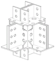
Fig. 3 is a schematic structural view of the central member unit.
Fig. 4 is a schematic view of the structure of the cross plate.
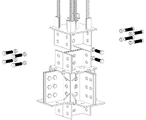
Fig. 5 is a schematic structural view of the center member unit and the upper column unit.
Fig. 6 is a schematic structural view of the beam member unit.
The reference numbers in the figures are: 1 is a central body, 2 is an upper connecting plate, 3 is a lower connecting plate, 4 is a groove-shaped connecting plate, 5 is a vertical splicing body, 6 is a fixing plate, 7 is an angle seat, 8 is a vertical splicing gap, 9 is a plate-type connecting plate, 10 is a transverse splicing gap, 11 is a reinforcing seat, 12 is a web plate, 13 is an upper wing plate, 14 is a lower wing plate, 15 is a splicing opening, and 16 is a rib plate; 17 is a through hole, 18 is a abdication groove; 19 is a cross plate, 20 is a reinforcing steel bar, and 21 is a stirrup.
Detailed Description
The invention is further illustrated with reference to the following figures and examples.
Example 1: the embodiment aims at providing a prefabricated assembled beam column combination node of modularization that adopts bolted connection, mainly used realizes the bolted connection of beam column node, to current assembled connection structure, its structural stability is poor, relies on bolted connection's intensity too much, and need realize holding in the palm the crossbeam when the bolt butt joint, make the bolt hole correspond the back and carry out bolted connection, the construction is troublesome, based on this, this embodiment provides a prefabricated assembled beam column combination node of modularization that adopts bolted connection.
As shown in the figure, the modularized prefabricated assembled beam-column combined node adopting the bolt connection comprises an upper column unit, a central member unit, a lower column unit and a beam member unit; the central member unit is an integrally formed structure, and is centrally disposed, and the lower portion thereof is connected to the lower column unit, and the upper portion thereof is connected to the upper column unit, and the side surface thereof is connected to the beam member unit, and the central member unit is a regular polygon structure.
The embodiment specifically provides an assembled node structure that prefabricated post and prefabricated post are connected, precast beam and prefabricated post are connected for solve assembled node structure shear strength not high relatively, stability lower scheduling problem relatively. The node mainly comprises a central node member in six directions, I-shaped interface precast concrete columns and I-shaped interface precast concrete beams with staggered upper and lower flanges. The six-direction central component has six parts for connection, namely an upper surface and a lower surface which are used for connecting the column and the beam, and four same horizontal surfaces are used for connecting the column and the beam. The connection mode is bolt installation and fixation. The number of the connecting nodes of the bolts and the central member, the size of the joints, the size of the I-shaped steel, the size of the channel steel, the size of the angle steel and the like can be adjusted according to the building requirements, the structural characteristics and the operation space. The design is flexible, the factory modularization batch production can be realized, the construction operability is strong, the effective connection of the fully prefabricated assembled hybrid frame nodes is realized, and the rapid and healthy development of the assembled building is facilitated.
In a specific structure, the central member unit includes a central body 1, an upper web 2 and a lower web 3; the central body 1 is of a square structure, the side surface of the central body 1 is provided with a flat side wall, the upper part and the lower part of the central body are provided with an upper connecting plate 2 and a lower connecting plate 3, the upper connecting plate 2 is smaller than the lower connecting plate 3, groove-shaped connecting plates 4 are symmetrically fixed on the outer side surfaces of the upper connecting plate 2 and the lower connecting plate 3 at intervals, and a vertical splicing gap 8 is formed between the two groove-shaped connecting plates 4; in specific implementation, the groove-shaped connecting plates 4 are of U-shaped structures, the two groove-shaped connecting plates 4 form an I-shaped butt joint body at intervals, the butt joint body is located in the middle areas of the upper connecting plate and the lower connecting plate, and two bolt holes are formed in the three plates of each groove-shaped connecting plate.
The upper column unit and the lower column unit have the same structure and both comprise a fixed plate 6 and a vertical splicing body 5; the vertical splicing body 5 is in an I-shaped structure and is fixed on the inner side of the fixing plate, and a vertical beam frame is arranged on the outer side of the fixing plate 6; the vertical splicing bodies 5 are nested in the vertical splicing gaps 8, corresponding screw holes are formed in the web plates and wing plates of the vertical splicing bodies 5 and the groove-shaped connecting plates 4, and the screw holes are fixed through connecting bolts after being in one-to-one correspondence; thereby erect the web of splice body 5 and nested and fix in vertical concatenation clearance through the bolt that runs through, and by two cell type connecting plate centre gripping location, its pterygoid lamina is located the outside of cell type connecting plate to it is fixed to run through the connecting bolt that corresponds, and then erect the splice body and nested in the cell type connecting plate outside that can prepositioning, when the installation is fixed, directly assemble and can realize the accurate positioning equipment.
When the steel structure connecting structure is implemented, the length of the steel structure joints of the upper column unit and the lower column unit is the same as that of the upper and lower groove-shaped connecting plates of the central member, the rear surfaces of the upper and lower groove-shaped connecting plates are attached to the surfaces of the upper and lower groove-shaped connecting plates, the reserved bolt holes are aligned, the outer sides of the upper and lower connecting plates are provided with angle seats 7, and the vertical beam frame is fixed on the angle seats 7.
The side surface of the central body 1 is provided with plate-shaped connecting plates 9 at intervals, and a transverse splicing gap 10 is formed between the two plate-shaped connecting plates 9; in the embodiment, the inner sides of two parallel plate-shaped connecting plates 9 are fixed on the outer side wall of the central body 1 and are propped against the upper connecting plate 2 and the lower connecting plate 3 from top to bottom, and the upper parts of the plate-shaped connecting plates are exposed to form a supporting platform because the upper connecting plates are smaller than the lower connecting plates, so that a pre-stable foundation is provided for installing a transverse beam frame.
The beam member unit comprises a beam frame and a transverse splicing body; the transverse splicing body comprises an upper wing plate 13, a lower wing plate 14, a web plate 12 and a transverse beam frame; the upper portion and the lower part of web 12 respectively with last pterygoid lamina 13 and lower pterygoid lamina 14 fixed connection, wherein pterygoid lamina 14 is provided with the joint mouth 15 with the outer end of being connected of web 12 down, and the inboard of horizontal concatenation body is fixed with the crossbeam frame, and the crossbeam frame is when concrete implementation, and the both sides of web are fixed with multilayer floor 16, the crossbeam frame is fixed on floor 16, is provided with many reinforcing bars 20 on the crossbeam frame, connects through the stirrup between the reinforcing bar 20.
The beam component unit is obtained by that the steel bars in the beam pass through the reinforcing ribs and are connected with the I-shaped steel through bolts, and concrete which is not more than the position of the connecting bolt steel plate is poured, wherein the I-shaped steel is longer than the lower flange, bolt holes are reserved in the upper flange and the lower flange and a web plate, and a fracture-shaped splicing port with a rectangular section exists in the position of the lower flange of the web plate.
In specific implementation, the linear distance between the outer sides of the two steel plates on any side surface of the central component is the section width of the rectangular section of the flange on the lower side of the I-shaped steel web of the beam component unit; the interval length of the two steel plates is the thickness of an I-shaped steel web of the beam member unit, the web is nested in the transverse splicing gap, and the web is combined with the two steel plates on the side surface of the central member to achieve surface-to-surface joint and to align reserved bolt holes; the fracture of the rectangular section of the lower flange plate is just overlapped with the lower parts of the two steel plates on the side surface of the central component, so that the lower flange groove of the beam component unit is tightly attached to the two steel plates on the side surface of the central component. The upper wing plate is positioned on the upper parts of the plate-shaped connecting plate and the upper connecting plate, the upper wing plate is fixedly connected with the upper connecting plate through corresponding screw holes, the lower wing plate is positioned on the lower connecting plate, corresponding screw holes are formed in the web plate and the plate-shaped connecting plate, the lower wing plate and the lower connecting plate, and the screw holes are fixed through connecting bolts after being in one-to-one correspondence.
The embodiment is the layering construction when using, at first assemble the crossbeam frame, with the pterygoid lamina seat connecting plate down, correspond web and horizontal concatenation clearance, and inwards impel, then correspond the equipment that runs through the screw with connecting bolt and realize the crossbeam frame, then assemble surplus crossbeam frame one by one, then at construction erects the roof beam frame, with the vertical splice body nestification of I shape in vertical concatenation clearance, then fixed connection bolt can, the successive layer upwards promotes, then at the outside formwork of beam column node, with concrete placement wherein, the concrete can be full of the beam column node through the clearance, at last the form removal can.
Example 2: this example is substantially the same as example 1, except that: the present embodiment further describes a connection structure of a plate-like connection plate and an upper connection plate.
In the embodiment, the inner side of the plate-shaped connecting plate is provided with the abdicating groove 18, the upper connecting plate 2 is located in the abdicating groove 18 in a matching manner, and the upper part of the upper connecting plate 2 is flush with the upper part of the plate-shaped connecting plate.
The edge of the upper wing plate 13 protrudes out of the web plate 12, the lower wing plate 14 is flush with the web plate 12, screw holes are formed in the protruding portion of the upper wing plate and distributed on two sides of the web plate and the plate-type connecting plate, the horizontal steel plates on the upper portion and the lower portion of the central member are respectively attached to the upper flange and the lower flange of the beam member unit, and the reserved bolt hole positions of the central member are respectively aligned with the reserved bolt hole positions of the beam member unit one by one.
Middle-upper pterygoid lamina and pterygoid lamina homoenergetic are located to be set up in this embodiment, and its web is by two board-like connecting plate centre grippings, overall structure is stable, and joint strength is big.
Example 3: this example is substantially the same as example 1, except that: this embodiment has set up the stopper to the upper junction plate in this embodiment.
This embodiment is when implementing, and easy deformation between two board-like connecting plates causes the butt joint difficulty during the installation, and this embodiment has set up the stopper in order to make two board-like connecting plates can keep the interval between the two, is provided with the stopper during concrete implementation on the upper junction plate, and the stopper matching clamps in horizontal concatenation clearance.
Example 4: this example is substantially the same as example 1, except that: this embodiment further illustrates the structure of the central body.
In this embodiment, a cross plate 19 is disposed on the inner side of the central body, and through holes 17 that can be communicated with each other are disposed on the central body 1, the cross plate 19, the upper connecting plate 2 and the lower connecting plate 3, and the through holes are not only used for reducing the total weight, but also can pass through the beam-column joints.
The upper surface, the lower surface and the periphery of the central member are all provided with excavation treatment, the interior of the member is provided with crossed steel plates for hollowing treatment, after the beam-column nodes are assembled, a formwork is required to be supported on the outer sides of the beam-column nodes, then concrete is filled in the beam-column nodes, in order to enable the beam-column nodes to be filled with the concrete, the beam-column nodes are fully connected with the concrete, through holes are formed in the beam-column nodes, the concrete can enter the space through the through holes, and the beam-column nodes are built in the concrete.
Example 5: this example is substantially the same as example 1, except that: this embodiment further illustrates the structure of the cross plate.
In the embodiment, the fixing position of the cross plate corresponds to the transverse splicing gap, and the thickness of the cross plate is the same as that of the transverse splicing gap; in the embodiment, the thickness of the cross plate is the same as that of the web plate, so that the stress strength of the central body is enhanced, and the structural stability is improved.
A reinforcing seat 11 is arranged between the side surface of the central body and the upper connecting plate and the lower connecting plate, and the reinforcing seat 11 can further enhance the connection strength of the central body and the upper connecting plate and the lower connecting plate.
The upper connecting plate 2 and the lower connecting plate 3 are provided with corresponding cut angles, so that the edges of the upper connecting plate and the lower connecting plate are flush with the upper wing plate and the lower wing plate and correspond to each other.
The embodiment provides a modularized prefabricated beam-column combined node adopting bolt connection, which comprises an upper column unit, a central member, a beam member unit, a lower column unit and bolts for connecting all modules, wherein the node connection comprises the connection of the central member and the column unit and the connection of the central member and the beam member unit; the steel bars in the column unit are welded with the reserved angle steel, the poured concrete does not exceed the position of an I-shaped steel plate on the lower (upper) side of the connection, the joint part of the column unit is an I-shaped steel plate with a reserved bolt hole and can be attached to a groove-shaped connecting steel plate on the upper (lower) surface of a central member, and the central member and the column unit are connected by bolts at the positions of the groove-shaped connecting plate and the I-shaped steel joint.
The beam member unit beam inner steel bar penetrates through the stiffening rib and is connected with the I-shaped steel joint through the bolt, the poured concrete does not exceed the position of the connecting bolt steel plate, the beam member unit joint part is the I-shaped steel plate with reserved bolt holes, the upper flange and the lower flange of the I-shaped steel are unequal in length and the reserved bolt holes, and a groove is reserved in the center of the lower flange; the central member and the beam member unit are connected by bolts at the flange and the web positions.
In order to enable the joint of the steel bar in the column and the I-shaped steel of the column unit to be welded more firmly, the angle steel has a certain height. Meanwhile, a shear nail is arranged at the center of the steel plate in the horizontal direction of the I-shaped steel so as to improve the connection reliability of the concrete, the steel bar and the connector part of the I-shaped steel in the column.
In order to stabilize the structure of the central member, realize reasonable stress and facilitate later-stage node concrete pouring, each side surface comprises four supports with an upper support and a lower support, the upper support, the lower support and the periphery of the supports are all provided with holes, and the inside of the member is a cross-shaped crossed steel plate for hollowing treatment.
In order to ensure that the reinforcing steel bars in the beam can be more firmly connected with the I-steel joints of the column units, the I-steel in the beam is provided with stiffening ribs for hollowing treatment, and the I-steel part in the beam has a certain length so as to improve the shearing strength of the end part of the beam.
No matter in this embodiment central member is connected with the post unit or central member is connected with the roof beam component unit, the bolt hole that reserves should align one by one, and high strength bolt passes when supplying the equipment.
In the specific construction of the embodiment, firstly, the members are manufactured in a factory according to the determined sizes of the bolts, the central member connecting nodes, the joints, the I-shaped steel, the channel steel, the angle steel and the like in the connecting nodes.
The groove-shaped connecting steel plate at the lower part of the central component is spliced with the reserved I-shaped steel joint of the lower column unit, and when the groove-shaped connecting steel plate is completely attached to the reserved I-shaped steel joint and the reserved messy bolt holes are aligned, the groove-shaped connecting steel plate and the reserved I-shaped steel joint are effectively connected through the high-strength bolt. Splicing two steel plates with reserved bolt holes on the side surface of the central member with a beam member unit I-shaped steel web plate, wherein the beam member unit I-shaped steel web plate is arranged between the two steel plates on the side surface of the central member, so that the surfaces are attached to each other, and the bolt holes are aligned; the upper and lower horizontal steel plates with unequal shapes of the central component are attached to the upper and lower flanges of the beam component unit, so that the surfaces are attached to each other and the bolt holes are aligned; and finally, the high-strength bolt is used for realizing the effective connection of the two. When the central member is spliced with the beam member units, the central member is kept still, and the I-shaped steel webs of the beam member units vertically enter between two steel plates on the side surface of the central member from top to bottom. The connection mode is that only one side of the central component needs to be connected with the beam component unit, and the other three sides can be operated according to the method. Splicing the upper groove-shaped connecting steel plate of the central member with the reserved I-shaped steel joint of the upper column unit, and when the groove-shaped connecting steel plate is completely attached to the reserved I-shaped steel joint and the reserved messy bolt holes are aligned, effectively connecting the groove-shaped connecting steel plate and the reserved I-shaped steel joint through the high-strength bolt.
Claims (10)
1. The utility model provides an adopt bolted connection's prefabricated assembled beam column combination node of modularization which characterized in that: comprises an upper column unit, a central member unit, a lower column unit and a beam member unit; the central member unit comprises a central body, an upper connecting plate and a lower connecting plate; the side surface of the central body is provided with a flat side wall, the upper part and the lower part of the central body are provided with an upper connecting plate and a lower connecting plate, the upper connecting plate is smaller than the lower connecting plate, groove-shaped connecting plates are symmetrically fixed on the outer side surfaces of the upper connecting plate and the lower connecting plate at intervals, and a vertical splicing gap is formed between the two groove-shaped connecting plates; the side surface of the central body is provided with plate-shaped connecting plates at intervals, and a transverse splicing gap is formed between the two plate-shaped connecting plates; the upper column unit and the lower column unit have the same structure and respectively comprise a fixed plate and a vertical splicing body; the vertical splicing body is of an I-shaped structure and is fixed on the inner side of the fixing plate, and a vertical beam frame is arranged on the outer side of the fixing plate; the vertical splicing bodies are nested in the vertical splicing gaps, corresponding screw holes are formed in the vertical splicing bodies and the web plate and the wing plate of the groove-shaped connecting plate, and the screw holes are fixed through connecting bolts after being in one-to-one correspondence; the beam member unit comprises a beam frame and a transverse splicing body; the transverse splicing body comprises an upper wing plate, a lower wing plate, a web plate and a transverse beam frame; the upper part and the lower part of the web plate are respectively and fixedly connected with an upper wing plate and a lower wing plate, wherein the outer end of the lower wing plate connected with the web plate is provided with a splicing port, and the inner side of the transverse splicing body is fixedly provided with a transverse beam frame; the web is nested in the transverse splicing gap, the upper wing plate is positioned on the upper portions of the plate-shaped connecting plate and the upper connecting plate and fixedly connected with the upper connecting plate through corresponding screw holes, the lower wing plate is positioned on the lower connecting plate, corresponding screw holes are formed in the web and the plate-shaped connecting plate, the lower wing plate and the lower connecting plate, and the screw holes are fixed through connecting bolts after the screw holes are in one-to-one correspondence.
2. The bolted modular prefabricated assembled beam-column combination joint according to claim 1, wherein: the inboard of platelike connecting plate is provided with the groove of stepping down, the upper junction plate matches and is located in the groove of stepping down.
3. The bolted modular prefabricated assembled beam-column combination joint according to claim 2, wherein: the edge of the upper wing plate protrudes out of the web plate, the lower wing plate is flush with the web plate, screw holes are formed in the protruding portion of the upper wing plate, and the screw holes are distributed on the two sides of the web plate and the plate type connecting plate.
4. The bolted modular prefabricated assembled beam-column combination joint according to claim 2, wherein: and the upper connecting plate is provided with a limiting block, and the limiting block is matched and clamped in the transverse splicing gap.
5. The bolted modular prefabricated assembled beam-column combination joint according to claim 1, wherein: the central body is of a cube structure, the cross-shaped cross plates are arranged on the inner side of the central body, and through holes which can be communicated with each other are formed in the central body, the cross plates, the upper connecting plates and the lower connecting plates.
6. The bolted modular prefabricated assembled beam-column combination joint according to claim 1, wherein: the fixed position of the cross plate corresponds to the transverse splicing gap, and the thickness of the cross plate is the same as that of the transverse splicing gap.
7. The bolted modular prefabricated assembled beam-column combination joint according to claim 1, wherein: and a reinforcing seat is arranged between the side surface of the central body and the upper connecting plate and between the side surface of the central body and the lower connecting plate.
8. The bolted modular prefabricated assembled beam-column combination joint according to claim 1, wherein: the upper connecting plate and the lower connecting plate are provided with corresponding cut angles, so that the edges of the upper connecting plate and the lower connecting plate are flush and corresponding to the upper wing plate and the lower wing plate.
9. The bolted modular prefabricated assembled beam-column combination joint according to claim 1, wherein: the outer sides of the upper connecting plate and the lower connecting plate are provided with angle seats, and the vertical beam frame is fixed on the angle seats.
10. The bolted modular prefabricated assembled beam-column combination joint according to claim 1, wherein: and a plurality of layers of ribbed plates are fixed on two sides of the web plate, and the beam frame is fixed on the ribbed plates.
Priority Applications (1)
| Application Number | Priority Date | Filing Date | Title |
|---|---|---|---|
| CN202210225798.4A CN114575533A (en) | 2022-03-09 | 2022-03-09 | Modularized prefabricated assembled beam-column combined node adopting bolt connection |
Applications Claiming Priority (1)
| Application Number | Priority Date | Filing Date | Title |
|---|---|---|---|
| CN202210225798.4A CN114575533A (en) | 2022-03-09 | 2022-03-09 | Modularized prefabricated assembled beam-column combined node adopting bolt connection |
Publications (1)
| Publication Number | Publication Date |
|---|---|
| CN114575533A true CN114575533A (en) | 2022-06-03 |
Family
ID=81778885
Family Applications (1)
| Application Number | Title | Priority Date | Filing Date |
|---|---|---|---|
| CN202210225798.4A Pending CN114575533A (en) | 2022-03-09 | 2022-03-09 | Modularized prefabricated assembled beam-column combined node adopting bolt connection |
Country Status (1)
| Country | Link |
|---|---|
| CN (1) | CN114575533A (en) |
Citations (25)
| Publication number | Priority date | Publication date | Assignee | Title |
|---|---|---|---|---|
| JPH06341167A (en) * | 1993-05-31 | 1994-12-13 | Maeda Corp | Working method for concrete structure |
| JPH07133637A (en) * | 1993-11-10 | 1995-05-23 | Tokyu Constr Co Ltd | Structure of joint part of column and beam |
| JP2001032377A (en) * | 1999-07-22 | 2001-02-06 | Shigetada Baba | Joint structure between reinforced concrete column and reinforced beam |
| CN203347023U (en) * | 2013-06-26 | 2013-12-18 | 珠海市晶艺玻璃工程有限公司 | Steel structure cast steel joint |
| CN206090866U (en) * | 2016-09-13 | 2017-04-12 | 罗大威 | Board in group outer union roof beam, post node member for assembly type structure |
| CN207003651U (en) * | 2017-05-04 | 2018-02-13 | 石家庄铁道大学 | A kind of assembling steel plate barrel shape RCS space nodes |
| CN108193782A (en) * | 2018-02-02 | 2018-06-22 | 青岛理工大学 | A kind of prefabricated assembled modular frame node and its assembly method |
| CN108222262A (en) * | 2018-03-23 | 2018-06-29 | 柏林 | A kind of assembling structure of assembling type steel structure building |
| CN108442518A (en) * | 2018-04-20 | 2018-08-24 | 青岛理工大学 | Oblique outer ring plate assembly type cross connects bean column node |
| CN108505619A (en) * | 2017-02-24 | 2018-09-07 | 新世界中国地产有限公司 | Prefabricated construction system and its assemble method |
| CN108867872A (en) * | 2018-09-04 | 2018-11-23 | 中冶建筑研究总院有限公司 | One kind is for rigidly connected node structure of beam column of steel structure and preparation method thereof, Housing Structure System |
| CN109372130A (en) * | 2018-11-08 | 2019-02-22 | 合肥工业大学 | The novel full assembly concrete shaped section steel frame node of one kind and its construction method |
| CN208586747U (en) * | 2018-07-11 | 2019-03-08 | 上海应用技术大学 | Prefabricated PC beams of concrete column connected node |
| CN208870184U (en) * | 2018-09-04 | 2019-05-17 | 中冶建筑研究总院有限公司 | One kind being used for the rigidly connected node structure of beam column of steel structure and Housing Structure System |
| CN209025221U (en) * | 2018-09-18 | 2019-06-25 | 西安建筑科技大学 | A kind of Self-resetting concrete filled steel tube concrete frame joint of web strips energy consumption part |
| CN211948874U (en) * | 2019-12-13 | 2020-11-17 | 中民筑友房屋科技集团有限公司 | T-shaped node beam column connecting structure formed by two steel beams |
| CN213358930U (en) * | 2020-08-25 | 2021-06-04 | 杭州恒途钢结构有限公司 | Connecting structure of H-shaped steel beam and H-shaped steel column |
| CN113047454A (en) * | 2021-04-07 | 2021-06-29 | 青岛理工大学 | FRP (fiber reinforced plastic) steel concrete column and steel beam combined node and mounting method |
| EP3862499A1 (en) * | 2019-02-27 | 2021-08-11 | Qingdao University Of Technology | Fabricated steel-wood combined joint |
| CN214246102U (en) * | 2020-12-27 | 2021-09-21 | 沈阳建筑大学 | Prefabricated assembled steel frame structure |
| CN113482152A (en) * | 2021-07-02 | 2021-10-08 | 湖北工业大学 | Assembled steel node |
| CN113513089A (en) * | 2021-08-18 | 2021-10-19 | 青岛理工大学 | FRP (fiber reinforced plastic) wrapped crossed steel reinforced concrete column-H-shaped steel beam connecting node and mounting method |
| CN214738828U (en) * | 2021-01-07 | 2021-11-16 | 西京学院 | Steel construction assembled beam column connected node device |
| CN113718950A (en) * | 2021-07-30 | 2021-11-30 | 华北水利水电大学 | Novel rapid Assembly formula beam column nodal connection structure |
| US20220049491A1 (en) * | 2019-05-29 | 2022-02-17 | Imac Engineering Co., Ltd. | Construction method for plant facility and plant configuring module |
-
2022
- 2022-03-09 CN CN202210225798.4A patent/CN114575533A/en active Pending
Patent Citations (25)
| Publication number | Priority date | Publication date | Assignee | Title |
|---|---|---|---|---|
| JPH06341167A (en) * | 1993-05-31 | 1994-12-13 | Maeda Corp | Working method for concrete structure |
| JPH07133637A (en) * | 1993-11-10 | 1995-05-23 | Tokyu Constr Co Ltd | Structure of joint part of column and beam |
| JP2001032377A (en) * | 1999-07-22 | 2001-02-06 | Shigetada Baba | Joint structure between reinforced concrete column and reinforced beam |
| CN203347023U (en) * | 2013-06-26 | 2013-12-18 | 珠海市晶艺玻璃工程有限公司 | Steel structure cast steel joint |
| CN206090866U (en) * | 2016-09-13 | 2017-04-12 | 罗大威 | Board in group outer union roof beam, post node member for assembly type structure |
| CN108505619A (en) * | 2017-02-24 | 2018-09-07 | 新世界中国地产有限公司 | Prefabricated construction system and its assemble method |
| CN207003651U (en) * | 2017-05-04 | 2018-02-13 | 石家庄铁道大学 | A kind of assembling steel plate barrel shape RCS space nodes |
| CN108193782A (en) * | 2018-02-02 | 2018-06-22 | 青岛理工大学 | A kind of prefabricated assembled modular frame node and its assembly method |
| CN108222262A (en) * | 2018-03-23 | 2018-06-29 | 柏林 | A kind of assembling structure of assembling type steel structure building |
| CN108442518A (en) * | 2018-04-20 | 2018-08-24 | 青岛理工大学 | Oblique outer ring plate assembly type cross connects bean column node |
| CN208586747U (en) * | 2018-07-11 | 2019-03-08 | 上海应用技术大学 | Prefabricated PC beams of concrete column connected node |
| CN108867872A (en) * | 2018-09-04 | 2018-11-23 | 中冶建筑研究总院有限公司 | One kind is for rigidly connected node structure of beam column of steel structure and preparation method thereof, Housing Structure System |
| CN208870184U (en) * | 2018-09-04 | 2019-05-17 | 中冶建筑研究总院有限公司 | One kind being used for the rigidly connected node structure of beam column of steel structure and Housing Structure System |
| CN209025221U (en) * | 2018-09-18 | 2019-06-25 | 西安建筑科技大学 | A kind of Self-resetting concrete filled steel tube concrete frame joint of web strips energy consumption part |
| CN109372130A (en) * | 2018-11-08 | 2019-02-22 | 合肥工业大学 | The novel full assembly concrete shaped section steel frame node of one kind and its construction method |
| EP3862499A1 (en) * | 2019-02-27 | 2021-08-11 | Qingdao University Of Technology | Fabricated steel-wood combined joint |
| US20220049491A1 (en) * | 2019-05-29 | 2022-02-17 | Imac Engineering Co., Ltd. | Construction method for plant facility and plant configuring module |
| CN211948874U (en) * | 2019-12-13 | 2020-11-17 | 中民筑友房屋科技集团有限公司 | T-shaped node beam column connecting structure formed by two steel beams |
| CN213358930U (en) * | 2020-08-25 | 2021-06-04 | 杭州恒途钢结构有限公司 | Connecting structure of H-shaped steel beam and H-shaped steel column |
| CN214246102U (en) * | 2020-12-27 | 2021-09-21 | 沈阳建筑大学 | Prefabricated assembled steel frame structure |
| CN214738828U (en) * | 2021-01-07 | 2021-11-16 | 西京学院 | Steel construction assembled beam column connected node device |
| CN113047454A (en) * | 2021-04-07 | 2021-06-29 | 青岛理工大学 | FRP (fiber reinforced plastic) steel concrete column and steel beam combined node and mounting method |
| CN113482152A (en) * | 2021-07-02 | 2021-10-08 | 湖北工业大学 | Assembled steel node |
| CN113718950A (en) * | 2021-07-30 | 2021-11-30 | 华北水利水电大学 | Novel rapid Assembly formula beam column nodal connection structure |
| CN113513089A (en) * | 2021-08-18 | 2021-10-19 | 青岛理工大学 | FRP (fiber reinforced plastic) wrapped crossed steel reinforced concrete column-H-shaped steel beam connecting node and mounting method |
Non-Patent Citations (2)
| Title |
|---|
| 邓芃: "方钢管混凝土柱与钢梁全螺栓节点抗震性能试验研究", 《建筑结构学报》 * |
| 魏巍: "装配式钢结构全螺栓柱连接刚性节点的应用", 《建筑与装饰》 * |
Similar Documents
| Publication | Publication Date | Title |
|---|---|---|
| CN110056092B (en) | Connecting structure of bolting-inserting type upper and lower prefabricated shear walls and superimposed sheet and construction method | |
| CN210827935U (en) | Assembled modularization lightweight steel construction wall connection structure | |
| CN218757940U (en) | Multilayer modular building node coupling assembling | |
| CN114215179B (en) | Wet construction method for center pillar joint of steel beam floor system and steel frame wallboard system | |
| CN114575533A (en) | Modularized prefabricated assembled beam-column combined node adopting bolt connection | |
| CN218346250U (en) | Connecting structure of crossbeam-free high-penetrating V-shaped column joint | |
| CN212427537U (en) | Assembled steel construction building fixed establishment | |
| CN112049253B (en) | Truss body and concrete structure connecting node, truss and method | |
| CN212582723U (en) | Equipment base beam | |
| CN114215181A (en) | Steel beam floor system and steel frame wallboard system center pillar joint dry-type construction method | |
| CN114319854A (en) | Platform beam for overhanging structure | |
| CN210975497U (en) | Shear connector | |
| CN111677106A (en) | Conversion connection structure of variable cross-section joint reinforcing steel bars of assembled structural column and implementation method | |
| CN219773212U (en) | Steel beam and concrete beam connection node | |
| CN109707069A (en) | One kind connecting detachable prefabricated modularization shear wall and its assembly method based on fashioned iron | |
| CN212506735U (en) | Conversion connection structure of assembled structure post variable cross section node reinforcing bar | |
| CN215803310U (en) | Assembled design platform system of unloading | |
| CN220267177U (en) | Elevator well operation platform | |
| CN209891714U (en) | Connecting template between double T-shaped plate and beam component | |
| CN214613545U (en) | Assembled steel-wood trestle | |
| CN217680821U (en) | Prefabricated assembled stand board connection structure | |
| CN216075601U (en) | Assembled concrete column girder steel hybrid connection node | |
| CN220644741U (en) | Integrated assembled wall convenient to install | |
| CN214656368U (en) | Vertical connecting device suitable for steel-concrete composite beam bridge deck and steel beam body | |
| CN219451263U (en) | Combined steel beam |
Legal Events
| Date | Code | Title | Description |
|---|---|---|---|
| PB01 | Publication | ||
| PB01 | Publication | ||
| SE01 | Entry into force of request for substantive examination | ||
| SE01 | Entry into force of request for substantive examination | ||
| RJ01 | Rejection of invention patent application after publication |
Application publication date: 20220603 |
|
| RJ01 | Rejection of invention patent application after publication |