CN114559541A - High-performance fair-faced concrete mixing process and device - Google Patents
High-performance fair-faced concrete mixing process and device Download PDFInfo
- Publication number
- CN114559541A CN114559541A CN202210286268.0A CN202210286268A CN114559541A CN 114559541 A CN114559541 A CN 114559541A CN 202210286268 A CN202210286268 A CN 202210286268A CN 114559541 A CN114559541 A CN 114559541A
- Authority
- CN
- China
- Prior art keywords
- gear
- shaft
- stirring
- rod
- agitator
- Prior art date
- Legal status (The legal status is an assumption and is not a legal conclusion. Google has not performed a legal analysis and makes no representation as to the accuracy of the status listed.)
- Pending
Links
- 238000000034 method Methods 0.000 title claims abstract description 9
- 238000003756 stirring Methods 0.000 claims abstract description 115
- 239000000463 material Substances 0.000 claims abstract description 69
- XLYOFNOQVPJJNP-UHFFFAOYSA-N water Substances O XLYOFNOQVPJJNP-UHFFFAOYSA-N 0.000 claims abstract description 7
- 239000000203 mixture Substances 0.000 claims abstract description 6
- 238000009434 installation Methods 0.000 claims description 21
- 238000007789 sealing Methods 0.000 claims description 13
- 230000005540 biological transmission Effects 0.000 claims description 6
- 239000004744 fabric Substances 0.000 claims description 6
- 239000002994 raw material Substances 0.000 claims description 6
- 238000012216 screening Methods 0.000 claims 1
- 238000004519 manufacturing process Methods 0.000 abstract description 9
- 238000007599 discharging Methods 0.000 description 18
- 230000000694 effects Effects 0.000 description 7
- 244000309464 bull Species 0.000 description 6
- 238000010586 diagram Methods 0.000 description 3
- 230000009286 beneficial effect Effects 0.000 description 1
- 230000007547 defect Effects 0.000 description 1
- 238000012986 modification Methods 0.000 description 1
- 230000004048 modification Effects 0.000 description 1
Images


Classifications
-
- B—PERFORMING OPERATIONS; TRANSPORTING
- B28—WORKING CEMENT, CLAY, OR STONE
- B28C—PREPARING CLAY; PRODUCING MIXTURES CONTAINING CLAY OR CEMENTITIOUS MATERIAL, e.g. PLASTER
- B28C5/00—Apparatus or methods for producing mixtures of cement with other substances, e.g. slurries, mortars, porous or fibrous compositions
- B28C5/003—Methods for mixing
- B28C5/006—Methods for mixing involving mechanical aspects
-
- B—PERFORMING OPERATIONS; TRANSPORTING
- B28—WORKING CEMENT, CLAY, OR STONE
- B28C—PREPARING CLAY; PRODUCING MIXTURES CONTAINING CLAY OR CEMENTITIOUS MATERIAL, e.g. PLASTER
- B28C5/00—Apparatus or methods for producing mixtures of cement with other substances, e.g. slurries, mortars, porous or fibrous compositions
- B28C5/08—Apparatus or methods for producing mixtures of cement with other substances, e.g. slurries, mortars, porous or fibrous compositions using driven mechanical means affecting the mixing
- B28C5/0806—Details; Accessories
- B28C5/0831—Drives or drive systems, e.g. toothed racks, winches
-
- B—PERFORMING OPERATIONS; TRANSPORTING
- B28—WORKING CEMENT, CLAY, OR STONE
- B28C—PREPARING CLAY; PRODUCING MIXTURES CONTAINING CLAY OR CEMENTITIOUS MATERIAL, e.g. PLASTER
- B28C5/00—Apparatus or methods for producing mixtures of cement with other substances, e.g. slurries, mortars, porous or fibrous compositions
- B28C5/08—Apparatus or methods for producing mixtures of cement with other substances, e.g. slurries, mortars, porous or fibrous compositions using driven mechanical means affecting the mixing
- B28C5/0887—Apparatus or methods for producing mixtures of cement with other substances, e.g. slurries, mortars, porous or fibrous compositions using driven mechanical means affecting the mixing provided with sieves or filters
-
- B—PERFORMING OPERATIONS; TRANSPORTING
- B28—WORKING CEMENT, CLAY, OR STONE
- B28C—PREPARING CLAY; PRODUCING MIXTURES CONTAINING CLAY OR CEMENTITIOUS MATERIAL, e.g. PLASTER
- B28C5/00—Apparatus or methods for producing mixtures of cement with other substances, e.g. slurries, mortars, porous or fibrous compositions
- B28C5/08—Apparatus or methods for producing mixtures of cement with other substances, e.g. slurries, mortars, porous or fibrous compositions using driven mechanical means affecting the mixing
- B28C5/10—Mixing in containers not actuated to effect the mixing
- B28C5/12—Mixing in containers not actuated to effect the mixing with stirrers sweeping through the materials, e.g. with incorporated feeding or discharging means or with oscillating stirrers
- B28C5/16—Mixing in containers not actuated to effect the mixing with stirrers sweeping through the materials, e.g. with incorporated feeding or discharging means or with oscillating stirrers the stirrers having motion about a vertical or steeply inclined axis
-
- B—PERFORMING OPERATIONS; TRANSPORTING
- B28—WORKING CEMENT, CLAY, OR STONE
- B28C—PREPARING CLAY; PRODUCING MIXTURES CONTAINING CLAY OR CEMENTITIOUS MATERIAL, e.g. PLASTER
- B28C7/00—Controlling the operation of apparatus for producing mixtures of clay or cement with other substances; Supplying or proportioning the ingredients for mixing clay or cement with other substances; Discharging the mixture
- B28C7/16—Discharge means, e.g. with intermediate storage of fresh concrete
Landscapes
- Engineering & Computer Science (AREA)
- Mechanical Engineering (AREA)
- Structural Engineering (AREA)
- Chemical & Material Sciences (AREA)
- Dispersion Chemistry (AREA)
- Preparation Of Clay, And Manufacture Of Mixtures Containing Clay Or Cement (AREA)
- Mixers Of The Rotary Stirring Type (AREA)
Abstract
The invention relates to the technical field of concrete production, in particular to a high-performance clear water concrete mixing process and a high-performance clear water concrete mixing device. According to the invention, the stirring rods on the stirring shaft body can be driven to rotate through the rotation of the stirring shaft, so that the materials in the stirring barrel can be stirred and mixed, and the rotating connecting rod of the rotating shaft rotates, so that each stirring rod can rotate along with the rotation of the stirring shaft, the stirring rods can stir the materials in the stirring barrel more fully and mix the materials more uniformly, and the production quality of concrete can be effectively improved.
Description
Technical Field
The invention relates to the technical field of concrete production, in particular to a high-performance fair-faced concrete mixing process and device.
Background
Along with the rapid development of the building industry, the concrete is as indispensable material in the building field, it is also more and more to use, the concrete is usually made by multiple material according to certain proportion stirring mixture, premixing mixing apparatus and important in the production process of concrete, but current mixing apparatus can lead to the stirring to mix inadequately because of the inside material of equipment is too much when using, and then influence concrete production quality, and can not carry out more abundant stirring to the mixture of great volume, cause the inside jam of equipment easily, influence its use.
Disclosure of Invention
Technical problem to be solved
Aiming at the defects of the prior art, the invention provides a high-performance fair-faced concrete mixing process and a high-performance fair-faced concrete mixing device, and solves the problems of insufficient mixing caused by excessive materials and internal blockage of equipment easily caused by large-volume materials.
(II) technical scheme
In order to achieve the purpose, the invention adopts the technical scheme that:
high performance clear water concrete mix device, including the agitator, the ladle body upper end one side of agitator is provided with the feed inlet, the last surface mounting of agitator has the power delivery box, the upper end of power delivery box is provided with driving motor, the (mixing) shaft is installed to the agitator internal rotation, evenly distributed is provided with a plurality of puddler on the axle body of (mixing) shaft, be provided with fortune material auger on the axle body of (mixing) shaft, the lower extreme of agitator is provided with ejection of compact deflector, the bottom of ejection of compact deflector is provided with the discharge gate, the fixed surface of agitator installs the support frame.
Preferably, the power transmission box comprises an installation box, a rotating shaft, a first gear, a first installation rod, a second gear, a second installation rod, a third gear, a fourth gear and a first tooth, wherein one end of the stirring shaft is arranged in the installation box, the installation box is arranged on the upper surface of the stirring barrel, one end of the rotating shaft is arranged at the output end of the driving motor, and the other end of the rotating shaft sequentially penetrates through the installation box and the stirring barrel and is rotatably arranged at the bottom end of the inside of the stirring shaft.
Preferably, a first gear is fixedly mounted inside the mounting box and located at one end of the rotating shaft, a second gear is meshed with one side of the first gear, a first mounting rod is arranged at the center of the second gear, the other end of the first mounting rod is rotatably arranged on the inner wall of the upper end of the mounting box, and a third gear is meshed with one side, far away from the first gear, of the second gear.
Preferably, a second mounting rod is arranged at the center of the third gear, the other end of the second mounting rod is rotatably arranged on the inner wall of the upper end of the mounting box, a fourth gear is fixedly mounted on the lower surface of the third gear, one side of the fourth gear is meshed with the first teeth, and the first teeth are uniformly distributed on a shaft body at one end of the mounting box, wherein the stirring shaft is located in the mounting box.
Preferably, the stirring rod comprises a mounting ring, a driving bevel gear, a driven bevel gear, a driving rotating rod, a sun gear, a planetary gear, a driven rotating rod, a second tooth, a connecting rod, an arc-shaped mounting rod, a limiting spring and a sealing cover, the shaft body of the rotating shaft is uniformly provided with a plurality of driving bevel gears in a distributed manner and positioned in the stirring shaft, the two sides of each driving bevel gear are engaged with the driven bevel gears, and the center of each driven bevel gear is fixedly provided with the driving rotating rod.
Preferably, one end of each driving rotating rod, which is far away from the driven bevel gear, is rotatably arranged in a mounting ring, the end of each driving rotating rod is provided with a sun gear, the mounting rings are uniformly distributed on a shaft body of the stirring shaft, the outer surface of each sun gear is meshed with three planetary gears, one side of each planetary gear is meshed with a second tooth, and the second teeth are uniformly distributed on the inner wall of the mounting ring.
Preferably, a driven rotating rod is fixedly installed at the center of each planetary gear, the other end of each driven rotating rod penetrates through a sealing cover, a connecting rod is installed at the end of each driven rotating rod, and the sealing cover is rotatably arranged on the surface of one end, far away from the stirring shaft, of the mounting ring.
Preferably, a plurality of arc-shaped installation rods are uniformly distributed on the rod body of each connecting rod, limiting springs are arranged on the lower surfaces of the two ends of each arc-shaped installation rod, and the other ends of the limiting springs are arranged inside the connecting rods.
As preferred, the bottom inner wall of agitator and the top that is located ejection of compact deflector are provided with the material screen cloth, the gag lever post is installed to the bottom inner wall of ejection of compact deflector, the one end that driving motor was kept away from to the (mixing) shaft is passed the material screen cloth and is rotated the upper end of installing at the gag lever post, the bottom of ejection of compact deflector is provided with the blown down tank, the discharge gate sets up the lower extreme at the blown down tank, one side of discharge gate is provided with the control valve.
The high-performance fair-faced concrete mixing process specifically comprises the following operation steps of:
s1: adding raw materials, namely adding the raw materials into the stirring barrel through a feeding hole;
s2: preliminary mixing, wherein a rotating shaft is driven to rotate by a driving motor, so that the rotating shaft and a stirring shaft respectively rotate, the stirring shaft can drive a stirring rod on a shaft body to rotate by rotation, and materials in a stirring barrel can be stirred and mixed;
s3: a material conveying auger is arranged on the stirring shaft in a staggered manner with the stirring rod, and can convey materials accumulated at the bottom of the equipment to the upper end for secondary stirring and mixing;
s4: discharging the materials, discharging the materials through the material screen under the action of the discharging guide plate after the stirring is finished, and controlling the discharging by arranging a control valve
Compared with the prior art, the invention has the following beneficial effects:
1. the rotation of (mixing) shaft can drive the puddler of playing epaxial one and rotate, and then can stir the mixture to the material in the agitator, the rotation of pivot can drive every initiative bevel gear on its axle body and rotate, and then drive both sides and rotate rather than the driven bevel gear of meshing, at sun gear, planetary gear, the mounting ring is with under the second tooth effect of inner wall, make driven bull stick rotate thereupon, the connecting rod that drives the driven bull stick other end rotates, make every puddler its self also can rotate when following the (mixing) shaft pivoted, make its stirring to the inside material of agitator more abundant, it is more even to mix, can effectively improve the production quality of concrete.
2. Crisscross fortune material auger that is provided with the puddler on the (mixing) shaft, can carry the material of piling up in the equipment bottom to the upper end and stir, make its stirring more abundant, prevent to take place to block, reach the material screen cloth that passes through that the stirring reaches the requirement after accomplishing and discharge the material by the discharge gate under ejection of compact deflector, the pole of connecting rod is epaxial to install arc installation pole through two spacing springs, when the material caking becomes great volume, can exert great pressure to arc installation pole, great reaction force can appear under spacing spring's effect equally, and then can carry out more abundant stirring to the caking material of great volume, can prevent that it from causing the jam to equipment inside.
Drawings
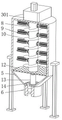
FIG. 1 is a schematic diagram of the overall structure of a high-performance bare concrete mixing device according to the invention;
FIG. 2 is a side view of the high performance bare concrete mixing apparatus of the present invention;
FIG. 3 is a schematic cross-sectional view taken along line A-A of FIG. 2 of the high performance bare concrete mixing apparatus of the present invention;
FIG. 4 is a schematic diagram of the internal structure of a power transmission box of the high-performance fair-faced concrete mixing device of the invention;
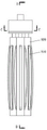
FIG. 5 is a schematic view of a concrete structure of a stirring shaft of the high-performance clear water concrete mixing device of the invention;
FIG. 6 is a side view of FIG. 5 of the high performance bare concrete mixing apparatus of the present invention;
FIG. 7 is a schematic cross-sectional view taken along line B-B of FIG. 5 of the high performance bare concrete mixing apparatus of the present invention;
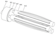
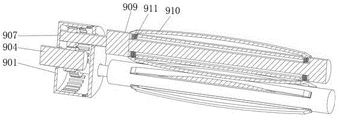
FIG. 8 is a schematic diagram of a concrete structure of a stirring rod of the high-performance fair-faced concrete mixing device of the invention;
FIG. 9 is the top view of FIG. 8 of the high performance bare concrete mixing apparatus of the present invention;
FIG. 10 is a schematic cross-sectional view taken at C-C of FIG. 9 of the high performance bare concrete mixing apparatus of the present invention;
FIG. 11 is a schematic cross-sectional view taken at D-D in FIG. 9 of the high-performance fair-faced concrete mixing apparatus of the present invention.
In the figure: 1. a stirring barrel; 2. a feed inlet; 3. a power delivery box; 301. installing a box; 302. a rotating shaft; 303. a first gear; 304. a first mounting bar; 305. a second gear; 306. a second mounting bar; 307. a third gear; 308. a fourth gear; 309. a first tooth; 4. a drive motor; 5. a discharge guide plate; 6. a discharge port; 7. a control valve; 8. a stirring shaft; 9. a stirring rod; 901. a mounting ring; 902. a drive bevel gear; 903. a driven bevel gear; 904. an active rotating rod; 905. a sun gear; 906. a planetary gear; 907. a driven rotating rod; 908. a second tooth; 909. a connecting rod; 910. an arc-shaped mounting rod; 911. a limiting spring; 912. a sealing cover; 10. a material conveying auger; 11. a support frame; 12. a material screen; 13. a limiting rod; 14. a discharge chute.
Detailed Description
The technical solutions in the embodiments of the present invention will be clearly and completely described below with reference to the embodiments of the present invention, and it is obvious that the described embodiments are only a part of the embodiments of the present invention, and not all of the embodiments. All other embodiments, which can be derived by a person skilled in the art from the embodiments given herein without making any creative effort, shall fall within the protection scope of the present invention.
Examples
As shown in fig. 1-11, high-performance clear water concrete mixing device, including agitator 1, one side of the barrel upper end of agitator 1 is provided with feed inlet 2, the upper surface mounting of agitator 1 has power delivery box 3, the upper end of power delivery box 3 is provided with driving motor 4, (mixing) shaft 8 is installed to 1 internal rotation of agitator, evenly distributed is provided with a plurality of puddler 9 on the axle body of (mixing) shaft 8, be provided with fortune material auger 10 on the axle body of (mixing) shaft 8, the lower extreme of agitator 1 is provided with ejection of compact deflector 5, the bottom of ejection of compact deflector 5 is provided with discharge gate 6, the fixed surface of agitator 1 installs support frame 11.
Through the technical scheme, the rotating shaft 302 is driven to rotate by arranging the driving motor 4, the third gear 307 is driven to rotate under the meshing action of the second gear 305, the first gear 303 and the third gear 307, the fourth gear 308 at the lower end of the third gear is driven to rotate, the stirring shaft 8 can be driven to rotate under the action of the first tooth 309 meshed with one side of the first gear 309, the rotating shaft 302 and the stirring shaft 8 can rotate respectively, the use is more convenient, the stirring rod 9 on the shaft body can be driven to rotate by the rotation of the stirring shaft 8, materials in the stirring barrel 1 can be stirred and mixed, each driving bevel gear 902 on the shaft body can be driven to rotate by the rotation of the rotating shaft 302, the two sides of the rotating shaft 903 are driven to rotate by the driven bevel gears 903 meshed with the driving rotating rod 904, the sun gear 905 can be driven to rotate by the driving of the sun gear 905, and the mounting ring 901 and the second tooth 908 on the inner wall of the mounting ring can be meshed between the sun gear 905 and the planet gear 906 Make every planetary gear 906 follow sun gear 905 and rotate, make driven bull stick 907 rotate thereupon, the connecting rod 909 that drives the driven bull stick 907 other end rotates, make every puddler 9 its self also can rotate when following (mixing) shaft 8 pivoted, make its stirring to 1 inside material of agitator more abundant, it is more even to mix, the result of use is better, can effectively improve the production quality of concrete, it has material carrying auger 10 to crisscross with puddler 9 on the (mixing) shaft 8, can carry the material of piling up in the equipment bottom to the upper end and stir, make its stirring more abundant, prevent to take place the jam, reach the material screen cloth 12 of passing through that reaches the requirement after the stirring is accomplished and discharge the material by discharge gate 6 under ejection of compact deflector 5's effect, can control the ejection of compact through setting up control valve 7, it is more convenient to use.
In this embodiment, the power transmission box 3 includes a mounting box 301, a rotating shaft 302, a first gear 303, a first mounting rod 304, a second gear 305, a second mounting rod 306, a third gear 307, a fourth gear 308, and a first tooth 309, one end of the stirring shaft 8 is disposed inside the mounting box 301, the mounting box 301 is disposed on the upper surface of the stirring barrel 1, one end of the rotating shaft 302 is disposed at the output end of the driving motor 4, the other end of the rotating shaft 302 sequentially passes through the mounting box 301 and the stirring barrel 1 and is rotatably disposed at the inner bottom end of the stirring shaft 8, one end of the rotating shaft 302 is axially and fixedly mounted with the first gear 303 inside the mounting box 301, one side of the first gear 303 is engaged with the second gear 305, the center of the second gear 305 is disposed with the first mounting rod 304, the other end of the first mounting rod 304 is rotatably disposed on the inner wall of the upper end of the mounting box 301, one side of the second gear 305 away from the first gear 303 is engaged with the third gear 307, a second mounting rod 306 is arranged at the center of the third gear 307, the other end of the second mounting rod 306 is rotatably arranged on the inner wall of the upper end of the mounting box 301, a fourth gear 308 is fixedly mounted on the lower surface of the third gear 307, one side of the fourth gear 308 is meshed with the first teeth 309, the first teeth 309 are uniformly distributed on a shaft body at one end of the stirring shaft 8 in the mounting box 301, the rotating shaft 302 is driven to rotate by arranging the driving motor 4, the third gear 307 is driven to rotate under the meshing action of the second gear 305 and the first gear 303 and the third gear 307, and further the fourth gear 308 at the lower end of the third gear is driven to rotate, the stirring shaft 8 can be driven to rotate under the action of the first teeth 309 meshed with one side of the third gear, so that the rotating shaft 302 and the stirring shaft 8 can rotate respectively, and the use is more convenient.
When the stirring shaft is specifically arranged, the stirring rod 9 comprises a mounting ring 901, a driving bevel gear 902, a driven bevel gear 903, a driving rotating rod 904, a sun gear 905, a planetary gear 906, a driven rotating rod 907, a second tooth 908, a connecting rod 909, an arc-shaped mounting rod 910, a limiting spring 911 and a sealing cover 912, wherein a plurality of driving bevel gears 902 are uniformly distributed and mounted on the shaft body of the rotating shaft 302 and positioned in the stirring shaft 8, the driven bevel gear 903 is meshed with two sides of each driving bevel gear 902, the driving rotating rod 904 is fixedly mounted at the center of each driven bevel gear 903, one end of each driving rotating rod 904 far away from the driven bevel gear 903 is rotatably arranged in the mounting ring 901, the end part of each driving rotating rod is provided with the sun gear 905, the mounting ring 901 is uniformly distributed and arranged on the shaft body of the stirring shaft 8, the outer surface of each sun gear 905 is meshed with three planetary gears 906, one side of each planetary gear 906 is meshed with the second tooth 908, the second teeth 908 are uniformly distributed on the inner wall of the mounting ring 901, a driven rotating rod 907 is fixedly arranged at the center of each planetary gear 906, the other end of each driven rotating rod 907 penetrates through a sealing cover 912, the end part of each driven rotating rod is provided with a connecting rod 909, the sealing cover 912 is rotatably arranged on the surface of one end of the mounting ring 901 far away from the stirring shaft 8, the stirring shaft 8 rotates to drive the stirring rod 9 on the stirring shaft body to rotate, so that the materials in the stirring barrel 1 can be stirred and mixed, the rotation of the rotating shaft 302 drives each driving bevel gear 902 on the shaft body to rotate, so that the driven bevel gears 903 with two sides meshed with the driving bevel gears are driven to rotate, the driving rotating rod 904 can drive the sun gear 905 to rotate, and each planetary gear 906 can rotate along with the sun gear 905 under the action of the second teeth 908 on the mounting ring 901 and the inner wall thereof through meshing between the sun gear 905 and the planetary gears 906, make driven bull stick 907 rotate thereupon, the connecting rod 909 that drives the driven bull stick 907 other end rotates, it itself also can rotate when following the (mixing) shaft 8 pivoted to make every puddler 9, it is more abundant to the stirring of 1 inside material of agitator, it is more even to mix, the result of use is better, can effectively improve the production quality of concrete, can carry out better sealing to every collar 901 under the condition that does not influence puddler 9 pivoted through the sealed lid 912 that rotates the setting, prevent that the material from getting into and influencing equipment operation in the (mixing) shaft 8.
In this application, all evenly distributed is provided with a plurality of arc installation pole 910 on the shaft of every connecting rod 909, the both ends lower surface of every arc installation pole 910 all is provided with spacing spring 911, the other end of every spacing spring 911 all sets up the inside at connecting rod 909, all install arc installation pole 910 through two spacing springs 911 on the shaft of every connecting rod 909, when the material caking becomes great volume, can apply great pressure to arc installation pole 910, great reaction force can appear equally under spacing spring's effect, and then can carry out more abundant stirring to the caking material of great volume, can prevent that it from causing the jam to equipment inside.
It should be noted that, the inner wall of the bottom of the stirring barrel 1 and the top of the discharging guide plate 5 are provided with a material screen 12, the inner wall of the bottom of the discharging guide plate 5 is provided with a limiting rod 13, one end of the stirring shaft 8, which is far away from the driving motor 4, passes through the material screen 12 and is rotatably installed at the upper end of the limiting rod 13, the bottom of the discharging guide plate 5 is provided with a discharging groove 14, the discharging hole 6 is arranged at the lower end of the discharging groove 14, one side of the discharging hole 6 is provided with a control valve 7, the material is discharged from the discharging hole 6 under the action of the discharging guide plate 5 through the material screen 12, which meets the requirement after the stirring is completed, the discharging can be controlled through the control valve 7, the use is more convenient, the limiting rod 13 can be supported when the stirring shaft 8 rotates, and the stirring work is more convenient.
Meanwhile, the invention also discloses a high-performance fair-faced concrete mixing process, which comprises the following operation steps:
s1: adding raw materials, namely adding the raw materials into the stirring barrel 1 through a feeding hole 2;
s2: preliminary mixing, wherein the rotating shaft 302 is driven to rotate by the driving motor 4, so that the rotating shaft 302 and the stirring shaft 8 respectively rotate, and the rotation of the stirring shaft 8 can drive the stirring rod 9 on the shaft body to rotate, so that the materials in the stirring barrel 1 can be stirred and mixed;
s3: a material conveying auger 10 is arranged on the stirring shaft 8 and staggered with the stirring rod 9, so that the materials accumulated at the bottom of the equipment can be conveyed to the upper end for secondary stirring and mixing;
s4: discharging the materials, discharging the materials through the material screen 12 under the action of the discharging guide plate 5 after the stirring is finished, and controlling the discharging by arranging the control valve 7
The working principle of the high-performance clear water concrete mixing device is as follows:
when stirring, materials are conveyed into the stirring barrel 1 through the feeding hole 2 for mixing and stirring, the rotating shaft 302 is driven to rotate through the driving motor 4, the first gear 303 is driven to rotate, the third gear 307 is driven to rotate under the meshing action of the second gear 305 and the first gear 303 and the third gear 307, the fourth gear 308 at the lower end of the third gear is driven to rotate, the stirring shaft 8 can be driven to rotate under the action of the first tooth 309 meshed with one side of the third gear, the rotating shaft 302 and the stirring shaft 8 can respectively rotate by arranging a plurality of gears to generate a rotation speed difference, the use is more convenient, the stirring shaft 8 rotates to drive the stirring rod 9 on the shaft body to rotate, the materials in the stirring barrel 1 can be further stirred and mixed, the rotation of the rotating shaft 302 drives each driving bevel gear on the shaft body to rotate, and further drives the driven bevel gears 903 meshed with the two sides to rotate, the driving rotating rod 904 can drive the sun gear 905 to rotate, the sun gear 905 and the planet gears 906 are meshed under the action of the mounting ring 901 and the second teeth 908 on the inner wall of the mounting ring, each planet gear 906 rotates along with the sun gear 905, the driven rotating rod 907 rotates along with the sun gear, the connecting rod 909 at the other end of the driven rotating rod 907 is driven to rotate, each stirring rod 9 can rotate along with the stirring shaft 8, the stirring rods can stir materials in the stirring barrel 1 more fully and uniformly, the using effect is better, the production quality of concrete can be effectively improved, the sealing cover 912 which is rotatably arranged can better seal each mounting ring 901 under the condition that the rotation of the stirring rods 9 is not influenced, the materials are prevented from entering the stirring shaft 8 to influence the operation of equipment, the arc-shaped mounting rods 910 are arranged on the rod bodies of each connecting rod 909 through two limit springs 911, when the material caking becomes great volume, can exert great pressure to arc installation pole 910, great reaction force can appear under spacing spring 911's effect equally, and then can carry out more abundant stirring to the caking material of great volume, can prevent that it from causing the jam to the equipment inside, it has material transport auger 10 with puddler 9 crisscross to be provided with on the (mixing) shaft 8, can carry the material of piling up in the equipment bottom to the upper end and stir, make its stirring more abundant, prevent to take place the jam, reach the material screen 12 of passing through that requires after the stirring is accomplished and discharge the material by discharge gate 6 under ejection of compact deflector 5's effect, can control the ejection of compact through setting up control valve 7, and is more convenient to use, can support it when (mixing) shaft 8 rotates through setting up gag lever post 13, it is convenient to carry out stirring work more.
The specific model specification of the driving motor 4 is Y315S-10.
The foregoing shows and describes the general principles and features of the present invention, together with the advantages thereof. It will be understood by those skilled in the art that the present invention is not limited to the embodiments described above, which are described in the specification and illustrated only to illustrate the principle of the present invention, but that various changes and modifications may be made therein without departing from the spirit and scope of the present invention, which fall within the scope of the invention as claimed. The scope of the invention is defined by the appended claims and equivalents thereof.
Claims (10)
1. High performance clear water concrete mix device, including agitator (1), its characterized in that: the utility model discloses a mixing machine, including agitator (1), power transmission case (3), driving motor (4), agitator (1) internal rotation, (mixing) shaft (8) are installed to the upper surface mounting of agitator (1), the upper end of power transmission case (3) is provided with driving motor (4), evenly distributed is provided with a plurality of puddler (9) on the axle body of (mixing) shaft (8), be provided with fortune material auger (10) on the axle body of (mixing) shaft (8), the lower extreme of agitator (1) is provided with ejection of compact deflector (5), the bottom of ejection of compact deflector (5) is provided with discharge gate (6), the fixed surface of agitator (1) installs support frame (11).
2. The high performance bare concrete mixing apparatus of claim 1, wherein: power transmission case (3) are including install bin (301), pivot (302), first gear (303), first installation pole (304), second gear (305), second installation pole (306), third gear (307), fourth gear (308), first tooth (309), the one end setting of (mixing) shaft (8) is in the inside of install bin (301), install bin (301) set up the upper surface at agitator (1), the one end setting of pivot (302) is at the output of driving motor (4), the other end of pivot (302) passes install bin (301), agitator (1) in proper order and rotates the inside bottom that sets up at (mixing) shaft (8).
3. The high performance bare concrete mixing apparatus of claim 2, wherein: the one end axle body of pivot (302) and the inside fixed mounting that is located install bin (301) have first gear (303), one side meshing of first gear (303) has second gear (305), second gear (305) center department is provided with first installation pole (304), the other end rotation of first installation pole (304) sets up the upper end inner wall at install bin (301), one side meshing that first gear (303) were kept away from in second gear (305) has third gear (307).
4. The high performance bare concrete mixing apparatus of claim 3, wherein: third gear (307) center department is provided with second installation pole (306), the other end of second installation pole (306) rotates the upper end inner wall that sets up in install bin (301), the lower fixed surface of third gear (307) installs fourth gear (308), one side and first tooth (309) intermeshing of fourth gear (308), first tooth (309) evenly distributed sets up on (mixing) shaft (8) is located the one end shaft body of install bin (301).
5. The high performance bare concrete mixing apparatus of claim 2, wherein: the stirring rod (9) comprises a mounting ring (901), a driving bevel gear (902), driven bevel gears (903), a driving rotating rod (904), a sun gear (905), a planetary gear (906), a driven rotating rod (907), second teeth (908), a connecting rod (909), an arc-shaped mounting rod (910), a limiting spring (911) and a sealing cover (912), wherein the shaft body of the rotating shaft (302) is uniformly distributed and provided with a plurality of driving bevel gears (902) in a stirring shaft (8), each of the two sides of the driving bevel gears (902) is engaged with the driven bevel gears (903), and each of the centers of the driven bevel gears (903) is fixedly provided with the driving rotating rod (904).
6. The high performance bare concrete mixing apparatus of claim 5, wherein: one end of each driving rotating rod (904) far away from the driven bevel gear (903) is rotatably arranged in the mounting ring (901), the end of each driving rotating rod is provided with a sun gear (905), the mounting rings (901) are uniformly distributed on the shaft body of the stirring shaft (8), the outer surface of each sun gear (905) is meshed with three planetary gears (906), one side of each planetary gear (906) is meshed with a second tooth (908), and the second teeth (908) are uniformly distributed on the inner wall of the mounting ring (901).
7. The high performance bare concrete mixing apparatus of claim 6, wherein: a driven rotating rod (907) is fixedly arranged at the center of each planetary gear (906), the other end of each driven rotating rod (907) penetrates through a sealing cover (912), a connecting rod (909) is arranged at the end of each sealing cover (912), and the sealing cover (912) is rotatably arranged on the surface of one end, far away from the stirring shaft (8), of the mounting ring (901).
8. The high performance bare concrete mixing apparatus of claim 7, wherein: a plurality of arc-shaped mounting rods (910) are uniformly distributed on the rod body of each connecting rod (909), the lower surfaces of two ends of each arc-shaped mounting rod (910) are provided with limiting springs (911), and the other end of each limiting spring (911) is arranged inside the connecting rod (909).
9. The high performance bare concrete mixing apparatus of claim 1, wherein: the utility model discloses a material screening device, including agitator (1), the bottom inner wall of agitator (1) and the top that is located ejection of compact deflector (5) are provided with material screen cloth (12), gag lever post (13) are installed to the bottom inner wall of ejection of compact deflector (5), the one end that driving motor (4) were kept away from in (mixing) shaft (8) is passed material screen cloth (12) and is rotated the upper end of installing at gag lever post (13), the bottom of ejection of compact deflector (5) is provided with blown down tank (14), discharge gate (6) set up the lower extreme in blown down tank (14), one side of discharge gate (6) is provided with control valve (7).
10. The high-performance fair-faced concrete mixing process is characterized by comprising the following steps: the method specifically comprises the following operation steps:
s1: adding raw materials, namely adding the raw materials into the stirring barrel (1) through the feeding hole (2);
s2: preliminary mixing, wherein a driving motor (4) drives a rotating shaft (302) to rotate, so that the rotating shaft (302) and a stirring shaft (8) respectively rotate, and the rotation of the stirring shaft (8) can drive a stirring rod (9) on a shaft body to rotate, so that materials in a stirring barrel (1) can be stirred and mixed;
s3: a material conveying auger (10) is arranged on the stirring shaft (8) and staggered with the stirring rod (9) and can convey materials accumulated at the bottom of the equipment to the upper end for secondary stirring and mixing;
s4: the material is discharged, the material is discharged from the discharge hole (6) under the action of the discharge guide plate (5) through the material screen (12) which meets the requirement after the stirring is completed, and the discharge can be controlled by arranging the control valve (7).
Priority Applications (1)
| Application Number | Priority Date | Filing Date | Title |
|---|---|---|---|
| CN202210286268.0A CN114559541A (en) | 2022-03-23 | 2022-03-23 | High-performance fair-faced concrete mixing process and device |
Applications Claiming Priority (1)
| Application Number | Priority Date | Filing Date | Title |
|---|---|---|---|
| CN202210286268.0A CN114559541A (en) | 2022-03-23 | 2022-03-23 | High-performance fair-faced concrete mixing process and device |
Publications (1)
| Publication Number | Publication Date |
|---|---|
| CN114559541A true CN114559541A (en) | 2022-05-31 |
Family
ID=81720371
Family Applications (1)
| Application Number | Title | Priority Date | Filing Date |
|---|---|---|---|
| CN202210286268.0A Pending CN114559541A (en) | 2022-03-23 | 2022-03-23 | High-performance fair-faced concrete mixing process and device |
Country Status (1)
| Country | Link |
|---|---|
| CN (1) | CN114559541A (en) |
Cited By (4)
| Publication number | Priority date | Publication date | Assignee | Title |
|---|---|---|---|---|
| CN115026952A (en) * | 2022-07-21 | 2022-09-09 | 公安县盛镶建材有限公司 | Concrete residual slurry recycling device |
| CN115229980A (en) * | 2022-07-18 | 2022-10-25 | 中航天建设工程集团有限公司 | Novel concrete mixing equipment for building construction and operation method |
| CN116277488A (en) * | 2022-11-25 | 2023-06-23 | 浙江雄宇混凝土构件有限公司 | Mixer for producing prestressed concrete pipe pile |
| CN116408032A (en) * | 2023-04-11 | 2023-07-11 | 连云港班庄水泥有限责任公司 | Alkali-activated retarding cementing material preparation device and method suitable for road engineering |
Citations (7)
| Publication number | Priority date | Publication date | Assignee | Title |
|---|---|---|---|---|
| CN205167213U (en) * | 2015-12-10 | 2016-04-20 | 北京正富混凝土有限责任公司 | Multiaxis concrete mixing device |
| CN106965317A (en) * | 2017-04-22 | 2017-07-21 | 徐勇 | Special automation mixed mud agitating device on a kind of construction site |
| CN207637555U (en) * | 2018-01-05 | 2018-07-20 | 四川蓝色未来机器科技有限公司 | A kind of continuous lead sheathing extruder purification attemperator |
| CN208372918U (en) * | 2018-04-13 | 2019-01-15 | 洛阳镁铝耐火材料有限公司 | A kind of novel refractory mixing device |
| CN208451925U (en) * | 2018-05-07 | 2019-02-01 | 沈阳胜鑫淼工业装备制造有限公司 | A kind of Testing of Grouting Material Behind Segments In Shield Tunnel mixed stirring device |
| DE212021000026U1 (en) * | 2021-02-22 | 2021-05-21 | Suzhou Shengte Intelligent Technology Co., Ltd | A dosing device for the printing and dyeing ingredients |
| CN215969409U (en) * | 2021-08-11 | 2022-03-08 | 田小林 | Concrete conveying device |
-
2022
- 2022-03-23 CN CN202210286268.0A patent/CN114559541A/en active Pending
Patent Citations (7)
| Publication number | Priority date | Publication date | Assignee | Title |
|---|---|---|---|---|
| CN205167213U (en) * | 2015-12-10 | 2016-04-20 | 北京正富混凝土有限责任公司 | Multiaxis concrete mixing device |
| CN106965317A (en) * | 2017-04-22 | 2017-07-21 | 徐勇 | Special automation mixed mud agitating device on a kind of construction site |
| CN207637555U (en) * | 2018-01-05 | 2018-07-20 | 四川蓝色未来机器科技有限公司 | A kind of continuous lead sheathing extruder purification attemperator |
| CN208372918U (en) * | 2018-04-13 | 2019-01-15 | 洛阳镁铝耐火材料有限公司 | A kind of novel refractory mixing device |
| CN208451925U (en) * | 2018-05-07 | 2019-02-01 | 沈阳胜鑫淼工业装备制造有限公司 | A kind of Testing of Grouting Material Behind Segments In Shield Tunnel mixed stirring device |
| DE212021000026U1 (en) * | 2021-02-22 | 2021-05-21 | Suzhou Shengte Intelligent Technology Co., Ltd | A dosing device for the printing and dyeing ingredients |
| CN215969409U (en) * | 2021-08-11 | 2022-03-08 | 田小林 | Concrete conveying device |
Cited By (7)
| Publication number | Priority date | Publication date | Assignee | Title |
|---|---|---|---|---|
| CN115229980A (en) * | 2022-07-18 | 2022-10-25 | 中航天建设工程集团有限公司 | Novel concrete mixing equipment for building construction and operation method |
| CN115229980B (en) * | 2022-07-18 | 2023-11-17 | 中航天建设工程集团有限公司 | Concrete mixing equipment for building construction and operation method |
| CN115026952A (en) * | 2022-07-21 | 2022-09-09 | 公安县盛镶建材有限公司 | Concrete residual slurry recycling device |
| CN115026952B (en) * | 2022-07-21 | 2023-10-20 | 公安县盛镶建材有限公司 | Concrete residual slurry recycling device |
| CN116277488A (en) * | 2022-11-25 | 2023-06-23 | 浙江雄宇混凝土构件有限公司 | Mixer for producing prestressed concrete pipe pile |
| CN116277488B (en) * | 2022-11-25 | 2023-11-14 | 浙江雄宇混凝土构件有限公司 | Mixer for producing prestressed concrete pipe pile |
| CN116408032A (en) * | 2023-04-11 | 2023-07-11 | 连云港班庄水泥有限责任公司 | Alkali-activated retarding cementing material preparation device and method suitable for road engineering |
Similar Documents
| Publication | Publication Date | Title |
|---|---|---|
| CN114559541A (en) | High-performance fair-faced concrete mixing process and device | |
| CN212312363U (en) | Cement stirring device | |
| CN215969409U (en) | Concrete conveying device | |
| CN111939782B (en) | Printing ink apparatus for producing | |
| CN216879024U (en) | Raw material mixing equipment for catalyst processing | |
| CN212978896U (en) | Powdery inorganic waterproof material production equipment | |
| CN217910088U (en) | Vitamin E premix mixing device | |
| CN208824308U (en) | A kind of feed stuff agitating device | |
| CN218358877U (en) | Mixing and stirring device | |
| CN215233929U (en) | Homogenizing mixer for producing macroelement water-soluble fertilizer | |
| CN215782902U (en) | Sealed mixer is used in control agent production is hindered to blade surface | |
| CN212701706U (en) | Pulp mixing device is used in paper core pipe processing | |
| CN213440524U (en) | Plastic color mixing machine with automatic feeding device | |
| CN211026128U (en) | Nutriment processing device | |
| CN210252134U (en) | Mixed type feed additive production is with smashing mixing arrangement | |
| CN108687956B (en) | Concrete compounding device for building | |
| CN220026873U (en) | Horizontal spiral ribbon stainless steel mixer | |
| CN219294429U (en) | Noise-reduction type automatic feeding and mixing integrated machine | |
| CN215693922U (en) | Production facility for triethanolamine | |
| CN221212265U (en) | Mixing device for building construction | |
| CN220589732U (en) | Fertilizer agitating unit is used in fertilizer production | |
| CN221875111U (en) | Environment-friendly dry-mixed mortar finished product unloader | |
| CN220443704U (en) | Raw material mixing equipment for quartz product processing | |
| CN214598819U (en) | A dustless feeding device for blown film production | |
| CN218854099U (en) | Compound fertilizer production is with mixing material loading machine |
Legal Events
| Date | Code | Title | Description |
|---|---|---|---|
| PB01 | Publication | ||
| PB01 | Publication | ||
| SE01 | Entry into force of request for substantive examination | ||
| SE01 | Entry into force of request for substantive examination |