CN114535376A - Bending equipment for processing lower ring of inner container - Google Patents
Bending equipment for processing lower ring of inner container Download PDFInfo
- Publication number
- CN114535376A CN114535376A CN202210179244.5A CN202210179244A CN114535376A CN 114535376 A CN114535376 A CN 114535376A CN 202210179244 A CN202210179244 A CN 202210179244A CN 114535376 A CN114535376 A CN 114535376A
- Authority
- CN
- China
- Prior art keywords
- assembly
- processing
- blank
- seat
- base
- Prior art date
- Legal status (The legal status is an assumption and is not a legal conclusion. Google has not performed a legal analysis and makes no representation as to the accuracy of the status listed.)
- Pending
Links
Images




Classifications
-
- B—PERFORMING OPERATIONS; TRANSPORTING
- B21—MECHANICAL METAL-WORKING WITHOUT ESSENTIALLY REMOVING MATERIAL; PUNCHING METAL
- B21D—WORKING OR PROCESSING OF SHEET METAL OR METAL TUBES, RODS OR PROFILES WITHOUT ESSENTIALLY REMOVING MATERIAL; PUNCHING METAL
- B21D11/00—Bending not restricted to forms of material mentioned in only one of groups B21D5/00, B21D7/00, B21D9/00; Bending not provided for in groups B21D5/00 - B21D9/00; Twisting
- B21D11/22—Auxiliary equipment, e.g. positioning devices
-
- B—PERFORMING OPERATIONS; TRANSPORTING
- B21—MECHANICAL METAL-WORKING WITHOUT ESSENTIALLY REMOVING MATERIAL; PUNCHING METAL
- B21D—WORKING OR PROCESSING OF SHEET METAL OR METAL TUBES, RODS OR PROFILES WITHOUT ESSENTIALLY REMOVING MATERIAL; PUNCHING METAL
- B21D11/00—Bending not restricted to forms of material mentioned in only one of groups B21D5/00, B21D7/00, B21D9/00; Bending not provided for in groups B21D5/00 - B21D9/00; Twisting
-
- B—PERFORMING OPERATIONS; TRANSPORTING
- B21—MECHANICAL METAL-WORKING WITHOUT ESSENTIALLY REMOVING MATERIAL; PUNCHING METAL
- B21D—WORKING OR PROCESSING OF SHEET METAL OR METAL TUBES, RODS OR PROFILES WITHOUT ESSENTIALLY REMOVING MATERIAL; PUNCHING METAL
- B21D43/00—Feeding, positioning or storing devices combined with, or arranged in, or specially adapted for use in connection with, apparatus for working or processing sheet metal, metal tubes or metal profiles; Associations therewith of cutting devices
- B21D43/02—Advancing work in relation to the stroke of the die or tool
- B21D43/04—Advancing work in relation to the stroke of the die or tool by means in mechanical engagement with the work
- B21D43/10—Advancing work in relation to the stroke of the die or tool by means in mechanical engagement with the work by grippers
- B21D43/105—Manipulators, i.e. mechanical arms carrying a gripper element having several degrees of freedom
Landscapes
- Engineering & Computer Science (AREA)
- Mechanical Engineering (AREA)
- Making Paper Articles (AREA)
Abstract
This patent belongs to inner bag processing equipment technical field, refers in particular to an equipment of buckling for processing inner bag lower lane, including the frame, still include: the conveying device is used for conveying the plane blank; the U folding device is used for processing the plane blank into a lower ring of the U-shaped inner container; the U folding device comprises a left folding assembly and a right folding assembly which are respectively used for folding the left end and the right end of the plane wool blank. This patent passes through the compound die driving piece is automatic to be realized the compound die of mold core and material seat, then buckles the processing subassembly on assembly and the right side assembly of buckling through a left side and rotate the processing of buckling in step, once only realizes the manufacturing to the plane hair blank.
Description
Technical Field
This patent belongs to inner bag processing equipment technical field, refers in particular to a equipment of buckling for processing inner bag lower lane.
Background
The oven liner is generally formed by splicing a U-shaped liner lower ring, a flat liner upper ring and a bottom cover through welding, wherein the difficulty in processing the U-shaped liner lower ring is processing two bent parts.
Traditional inner bag is circle down is formed through the stamping die punching press by circle blank down, because inner bag is circle material coefficient of resilience difference down, and traditional stamping die's last lower mould size is fixed, leads to stamping die to add man-hour this time, and the inner bag is circle down the machining dimension that the department of buckling is not of uniform size, the qualification rate is low, production efficiency hangs down the scheduling problem, can't satisfy current processing demand.
Disclosure of Invention
The purpose of this patent is to provide a simple structure, size are buckled the equipment of buckling that the precision is high, production efficiency is high is used for processing inner bag lower lane.
The purpose of this patent is so realized:
the utility model provides an equipment of buckling for processing inner bag lower lane, includes the frame, still includes:
the conveying device is used for conveying the plane blank; and
the U-folding device is used for processing the plane blank into a lower ring of the U-shaped inner container;
wherein, roll over the U device and include that the left side is buckled the assembly and is buckled the assembly with the right side, be used for buckling the both ends about the plane blank respectively, the left side is buckled the assembly and is buckled the assembly with the right side and all includes:
the base is arranged on the rack;
the material seat is fixed on the base and used for supporting the plane blank;
the die core is connected with a die closing driving piece, and the die closing driving piece drives the die core to move to the material seat and is used for limiting the plane rough blank between the die core and the material seat; and
and the processing assembly comprises a rotary driving part and a pressing roller, wherein the rotary driving part drives the pressing roller to rotate, so that the pressing roller rolls along the outer contour of the mold core to bend one side of the plane blank.
Further, the base comprises a front base and a rear base, the front base and the rear base are both provided with processing seats, and the compression roller is fixed between the two processing seats; the rotary driving part comprises a driving motor arranged on one of the processing seats.
Further, be equipped with processing even board between the processing seat, processing is equipped with the pre-compaction subassembly even on the board, and it includes:
the pressing block is arranged on the processing connecting plate and is abutted against the pressing roller; and
and the compression driving piece is connected with the compression block and used for providing compression force for the compression block.
Further, an outer support is further arranged on the processing connecting plate and used for supporting the outer end of the plane blank when the plane blank is placed on the material seat.
Furthermore, one side of the base is provided with an auxiliary base body,
the die assembly driving part comprises a C-shaped swinging frame with the middle part rotatably connected to the auxiliary base body, the outer end of the swinging frame is provided with the die core, and the inner end of the swinging frame is provided with a hydraulic push rod for driving the swinging frame to rotate or reset from top to bottom.
Furthermore, positioning pins are arranged at two ends of the mold core, positioning seats corresponding to the positioning pins are arranged on the base, positioning grooves are formed in the positioning seats, and when the mold closing driving piece drives the mold core to abut against the material seat, the positioning pins are located in the positioning grooves.
Further, the below of base is equipped with first slide rail set spare, including setting up first slider on the base and setting up first slide rail in the frame.
Further, the transportation device includes:
the conveying assembly is connected with the U folding device and used for driving the planar blank to move linearly; and
the lifting assembly drives the conveying assembly to enter a lifting state or a descending state and is used for enabling the plane blank to move up and down;
wherein the delivery assembly comprises:
the support frame is connected with the lifting assembly;
the two supporting rails are respectively fixed at the left end and the right end of the supporting frame and used for supporting the plane blank; and
the linear driving part is arranged on the supporting track or the supporting frame and is used for driving the plane blank to move on the supporting track;
when the conveying assembly is in a lifting state, the plane blank is higher than the material seat of the U-folding device;
when the conveying assembly conveys the plane blank materials into the U-folding device, the lifting assembly drives the conveying assembly to descend, and the plane blank materials fall on the material seat.
Further, the linear drive further comprises:
and the carrying rail is fixed on the support frame between the two support rails, and a carrying gripper for gripping the plane blank is arranged on the carrying rail.
The discharging device is arranged on the rear side of the discharging device, is connected with the conveying device and is used for removing the processed lower ring of the U-shaped liner; the blanking device comprises:
the blanking seat is used for placing the processed lower ring of the U-shaped inner container, and the height of the blanking seat is lower than that of the conveying assembly in a lifting state and higher than that of the conveying assembly in a descending state;
the two-axis positioner is arranged on one side of the blanking seat; and
the blanking gripper is driven by the double-shaft positioner and is used for gripping the lower ring of the U-shaped inner container;
after the conveying device conveys the lower ring of the U-shaped liner to the blanking seat, the lower ring is grabbed and conveyed by the blanking gripper;
the first carrying gripper and the second carrying gripper are arranged on the carrying track and are synchronously driven by the linear driving piece; the first carrying hand grip is used for sending the plane blank material into the U-folding device, and the second carrying hand grip is used for sending the processed lower ring of the U-shaped liner into the blanking device.
Compared with the prior art, the patent has the outstanding and beneficial technical effects that:
1. this patent passes through the compound die driving piece is automatic to be realized the compound die of mold core and material seat, then buckles the processing subassembly on assembly and the right side assembly of buckling through a left side and rotate the processing of buckling in step, once only realizes the manufacturing to the plane hair blank. To the different circumstances of material coefficient of resilience, because the rotation driving piece in this patent is driving motor, through control driving motor's turned angle, can effectively change the stroke of compression roller roll extrusion on the mold core outline, ensure that the efficient processes out the U-shaped inner bag lower ring that meets the requirements to the qualification rate and the production efficiency of product have been improved. The rotary driving piece in this patent can also adopt servo cylinder, but, driving motor compares in servo cylinder, and its control accuracy is higher, and easy operation only can carry out accurate control through configuration electric circuit.
2. The lifting assembly drives the conveying assembly to ascend or descend, so that the plane blank is quickly conveyed, and the U-shaped folding device with a complex structure can be bypassed in the conveying process, so that the plane blank is quickly and conveniently conveyed, and the productivity is improved.
3. The invention adopts the carrying gripper to grip the plane blank for carrying, and the gripper can grip and transport the plane blank for carrying, so that the running distance of the plane blank is more accurate, and the plane blank is prevented from running out of place or being blocked in a transport device.
Drawings
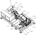
Fig. 1 is a schematic structural view of a bending apparatus.
Fig. 2 is a schematic structural view of the U-folding device.
Fig. 3 is a side sectional view of the U-folding device.
Fig. 4 is an enlarged view at a in fig. 3.
Fig. 5 is an enlarged view at B in fig. 3.
FIG. 6 is a schematic exploded view of the right bend assembly.
Fig. 7 is a schematic view of the processing assembly during processing.
FIG. 8 is a schematic view of the processing assembly when unprocessed.
Fig. 9 is a schematic structural view of the mold core.
Fig. 10 is a schematic structural view of the sub-mount.
Fig. 11 is a schematic view of the structure of the transport device in the bending apparatus.
Fig. 12 is a schematic view of the structure of the transportation device.
Fig. 13 is a schematic view of the structure at the lifting seat.
Fig. 14 is a schematic view of the transport device in transport.
Fig. 15 is a schematic structural view of the two-axis positioner.
Fig. 16 is a schematic structural view of the biaxial positioner during transportation.
The reference numerals in the figures denote the meanings:
1. a frame;
2. a transportation device; 21. a delivery assembly; 211. a support frame; 212. a support rail; 213. carrying a rail; 214. a rolling member; 215. a first carrying gripper; 216. a second carrying gripper; 22. a lifting assembly; 221. a lifting seat; 222. a hoisting motor; 223. lifting the rack; 224. lifting the slide rail; 225. lifting the slide block; 23. a centering assembly; 231. a centering seat; 232. A second slide rail assembly; 233. pushing the plate; 24. a first position; 25. a second position; 26. a third position;
3. a U folding device; 31. a left bending assembly; 32. a right bending assembly; 33. a base; 331. a front base; 332. a rear base; 333. positioning seats; 334. positioning a groove; 335. a base plate; 34. a material seat; 35. a mold core; 351. positioning pins; 36. a die assembly driving member; 361. a sub base body; 362. swinging and rotating the frame; 3621. a front frame body; 3622. a rear frame body; 363. a hydraulic push rod; 3631. A rotating joint; 364. a drive link plate; 365. linkage connecting plates; 37. processing the assembly; 371. processing a base; 372. a compression roller; 373. Processing a connecting plate; 374. rotating the driving member; 38. a pre-pressing component; 381. a compression block; 3811. a compaction groove; 382. compressing the driving member; 383. an outer support; 39. a first slide rail assembly; 391. a first slider; 392. a first slide rail;
4. a blanking device; 41. a blanking seat; 42. two-axis positioner; 421. a rotating seat; 422. rotating the block; 43. a blanking gripper; 431. grabbing a frame; 432. a first suction cup; 433. a second suction cup;
91. a planar blank; 92. a U-shaped inner container lower ring.
Detailed Description
This patent is further described below in conjunction with specific examples:
a bending device for processing a lower ring of an inner container is shown in figures 1-16 and comprises a frame 1, and a conveying device 2, a U-folding device 3 and a blanking device 4 which are arranged on the frame 1. The conveying device 2 is used for conveying the plane blank 91 to the U folding device 3, the plane blank 91 is processed through the U folding device 3, the plane blank 91 is changed into a U-shaped inner container lower ring 92, then the plane blank is conveyed into the blanking device 4 through the conveying device 2, and the processed U-shaped inner container lower ring 92 is moved away from the bending device through the blanking device 4.
The U folding device 3 in this patent comprises a left folding assembly 31 and a right folding assembly 32, wherein the left folding assembly 31 and the right folding assembly 32 are used for folding the left end and the right end of the plane blank 91. The left bending assembly 31 and the right bending assembly 32 have substantially the same structure, and each of them includes:
a base 33 mounted on the frame 1;
the material seat 34 is fixed on the base 33 and used for supporting the plane blank 91;
the mold core 35 is connected with a mold closing driving part 36, and the mold closing driving part 36 drives the mold core 35 to move to the material seat 34 so as to limit the plane blank 91 between the mold core 35 and the material seat 34; and
a processing assembly 37 including a processing seat 371, a rotary drive 374 and a pressure roller 372; the processing seat 371 is driven to rotate by a rotary driving part 374, and a pressing roller 372 matched with the mold core 35 is eccentrically arranged on the processing seat 371.
As shown in fig. 2, in a single bending assembly, the base 33 includes a front base 331 and a rear base 332, the base 33 further includes a bottom plate 335, and the bottom plate 335 is connected to the frame 1; the front base 331 and the rear base 332 are fixed to the front and rear ends of the upper portion of the bottom plate 335, respectively. The front base 331 and the rear base 332 are two vertical panels disposed on the front and rear ends of the bottom plate 335, and a hollow portion for placing the flat blank 91 is formed between the front base 331 and the rear base 332, so as to facilitate the processing of the flat blank 91.
Furthermore, an extension block is respectively disposed on one side of the front base 331 and the rear base 332 facing the hollow portion, and the material seat 34 is disposed on the top of the two extension blocks. As shown in fig. 2 and 6, the material seat 34 is a square column disposed above the extension block, the square column has an upper plane, when the flat blank 91 is placed on the bottom plate 335, the front and rear sides of one end of the flat blank 91 are respectively located on the square column, and the flat blank 91 is supported by the square column.
Further, processing seat 371 is equipped with two, and it is fixed respectively the top of preceding base 331 and back base 332, every processing seat 371 all is equipped with two through-holes from top to bottom, including last through-hole and lower through-hole, is equipped with the bearing spare in the lower through-hole of processing seat 371, the both ends of compression roller 372 are arranged in the lower through-hole of two processing seats 371 respectively, through the bearing spare is fixed, and makes through this bearing spare compression roller 372 rotates and sets up in the through-hole down. The upper through hole of the processing seat 371 is used for connecting the processing seat 371 with the front base 331 and the rear base 332, so as to realize the rotary connection of the processing seat 371 with the front base 331 or the rear base 332; as shown in fig. 6-8, in the front base 331, the processing seat 371 is arranged on the inner side of the front base 331, a connecting through hole is arranged on the processing seat 371, and the rotary driving member 374 is arranged on the outer side of the processing seat 371; in this embodiment, the rotary driving member 374 includes a driving motor, which may be a servo motor, and a motor shaft of the servo motor passes through the connecting through hole and is fixed to the upper through hole of the processing seat 371; in the rear base 332, a connecting through hole is also formed in the rear base 332, and a bearing member is provided through the connecting through hole and the upper through hole of the processing seat 371, so that the processing seat 371 is rotatably connected to the rear base 332 through the bearing member. At this time, the rotary driving member 374 can drive the processing seat 371 located at the front base 331 to rotate, the pressure roller 372 between the two processing seats 371 is in force transmission to drive the processing seat 371 located at the rear base 332 to rotate, and the pressure roller 372 is eccentrically driven to rotate.
In some embodiments, the processing seat 371 may not be provided, and the pressing roller 372 is configured in a "U" shape and connected to the base to realize eccentric rolling of the pressing roller 372; the advantage of adding the processing seat 371 is to increase the stability of the rolling of the pressing roller 372.
Furthermore, auxiliary seat bodies 361 are respectively arranged at the sides of the front base 331 and the rear base 332, and the auxiliary seat bodies 361 are used for installing the mold core 35 and the mold closing driving member 36. It should be noted that the structures of the sub-base 361 connected to the front base 331 and the rear base 332 are substantially the same, so for convenience of description, the front base 331 is taken as an example for description in this embodiment; as shown in fig. 6, 9 and 10, on the front base 331, the sub-base 361 is approximately "l", and the sub-base 361 and the front base 331 are connected to form a plate member in a "U" shape; the die closing driving part 36 comprises a C-shaped swinging frame 362 with the middle part rotatably connected to the auxiliary base 361, the outer end of the swinging frame 362 is provided with the die core 35, and the inner end of the swinging frame 362 is provided with a hydraulic push rod 363 for driving the swinging frame 362 to rotate or reset from top to bottom. Because the base 33 includes a front base 331 and a rear base 332, correspondingly, there are two swing frames 362, which include a front frame body 3621 and a rear frame body 3622, a driving connecting plate 364 and a linkage connecting plate 365 are connected between the front frame body 3621 and the rear frame body 3622, the driving connecting plate 364 is disposed between the inner ends of the front frame body 3621 and the rear frame body 3622, and the linkage connecting plate 365 is provided with a rotating joint 3631 rotatably connected with the hydraulic push rod 363; the linkage connecting plate 365 is disposed at an end of the front frame body 3621 and an end of the rear frame body 3622, where the mold core 35 is disposed, and is used for connecting the front frame body 3621 and the rear frame body 3622 which are separately disposed to relatively stabilize the front frame body 3621 and the rear frame body 3622.
In some embodiments, the sub-seat 361 can be integrally formed with the base 33, or separately disposed beside the front base 331 and the rear base 332, so that the mold core 35, the mold clamping driving member 36 and the processing component 37 on the sub-seat 361 only need to correspond to each other.
As shown in fig. 9, the mold core 35 is a long strip, and the mold core 35 has a rolling side adapted to fit with the pressing roller 372. As shown in fig. 3, when the U folding device 3 works, the planar blank 91 is first placed on the material seat 34, and then the hydraulic push rod 363 works to drive the swing frame 362 to rotate around the rotation connection point of the swing frame and the sub-seat body 361, so that the outer end of the swing frame 362 moves from top to bottom, and the mold core 35 at the outer end of the swing frame 362 abuts against the upper side of the planar blank 91 above the material seat 34, so as to perform mold closing. In this patent, in order to facilitate the display of the bent structure of the flat blank 91, in fig. 3-5, the left bending assembly 31 and the right bending assembly 32 of the single U-folding device 3 respectively display the structure of the flat blank 91 in the bent state and the non-bent state. As shown in fig. 4 and 5, when the machining assembly 37 works, the machining seat 371 rotates to drive the pressing roller 372 to abut against the rolling side of the mold core 35, and rolls along the outer contour of the rolling side, so as to bend one end of the planar blank 91. In the patent, the planar blank 91 is bent into the U-shaped inner container lower ring 92, that is, the corner part of the U-shaped inner container lower ring 92 is arc-shaped, so that an arc surface is arranged on the rolling side of the mold core 35, and the angle of the arc surface is at least 90 degrees, so as to adapt to the rolling processing of the pressing roller 372; in this embodiment, the angle of the arc surface is 180 degrees, so that the manufacturer can properly make the rolling angle of the pressing roller 372 exceed 90 degrees, thereby preventing the produced U-shaped liner lower ring 92 from being out of standard due to the rebound of the material of the flat blank 91, and setting the angle of the arc surface on the rolling side to 180 degrees, so as to provide a rolling space for the pressing roller 372. It should be noted that the resilience of the planar blank 91 is affected by the material and the processing environment of the planar blank 91, and when the material or the processing environment of the planar blank 91 is different, the resilience of the planar blank 91 is also different, and accordingly, the rolling angle of the pressing roller 372 needs to be changed for adaptation; and because compression roller 372 in this patent is controlled by servo motor, servo motor can freely control compression roller 372 pivoted angle to can satisfy the different processing demands of equipment. In fact, an inner container lower ring welding device is further arranged behind the bending device, and the bent U-shaped inner container lower ring 92 is sent to the inner container lower ring welding device for welding; the inner container lower ring welding equipment is provided with measuring equipment for measuring whether the U-shaped inner container lower ring 92 is standard or not, if the U-shaped inner container lower ring 92 is not standard, the bending deviation condition of the U-shaped inner container lower ring 92 is recorded, related data are sent into the bending equipment, and the bending equipment adjusts the rolling angle value of the pressing roller 372 according to the related data, so that closed-loop automatic adjustment is realized; in addition, the measuring device can also be arranged in the bending device disclosed in the patent, for example, on a conveying device or a blanking device behind the U folding device, and the measuring device can also realize closed-loop automatic adjustment.
It should be noted that, since the present patent is provided with the left bending assembly 31 and the right bending assembly 32, the left bending assembly 31 and the right bending assembly 32 work simultaneously to perform bending processing on the left and right ends of the planar blank 91 simultaneously.
This patent is through the compound die driving piece 36 realizes the compound die of mold core 35 and material seat 34 automatically, then buckles the processing subassembly 37 on assembly 31 and the right side assembly 32 through a left side and rotates in step and buckle the processing, once only realizes the manufacturing to plane blank 91. To the different circumstances of material coefficient of resilience, because the rotation driving piece 374 in this patent is driving motor, through control driving motor's turned angle, can effectively change the stroke of compression roller 372 rolling on mold core 35 outline, ensure that the efficient processing goes out the U-shaped inner bag lower ring 92 that meets the requirements to the qualification rate and the production efficiency of product have been improved. The rotary driving part 374 in the patent can also adopt a servo oil cylinder, but the driving motor is higher in control precision compared with the servo oil cylinder, and the operation is simple, and the precise control can be carried out only by configuring an electric circuit.
Further, a processing connecting plate 373 is arranged between the two processing seats 371, a pre-pressing assembly 38 is arranged on the processing connecting plate 373, and the pre-pressing assembly 38 comprises:
a pressing block 381 which is provided on the processing connecting plate 373 and abuts against the pressing roller 372; and
and the compression driving part 382 is connected with the compression block 381 and is used for providing compression force for the compression block 381.
As shown in fig. 6 to 8, the pressing driving member 382 is a servo cylinder disposed on the processing connecting plate 373, and the pressure of the servo cylinder can be adjusted according to the processing requirement; the pressing block 381 is driven by the motor push rod to move, and a pressing groove 3811 for accommodating the pressing roller 372 is formed in the pressing block 381. The compression roller 372 is at the both ends of the compression roller 372 when the plane blank 91 is rolled, because the fixed point of the compression roller 372 is at the both ends of the compression roller 372, when the compression roller 372 is rolled, the pressure of the two ends of the compression roller 372 to the plane blank 91 is large, the pressure of the middle part of the compression roller 372 to the plane blank 91 is relatively small, so that the shape of the U-shaped inner container pressing ring 92 rolled out due to the unbalanced stress of the plane blank 91 is not standard, and the product cannot be used. The pre-pressing assembly 38 can apply a pre-tightening force with a certain strength to the pressing roller 372, so that the acting force on the pressing roller 372 on the plane blank 91 is the same everywhere, and thus the bending angle and the bending shape of the plane blank 91 can be more accurate through the pre-pressing assembly 38, which is beneficial to improving the bending quality. The setting compress tightly groove 3811 can make the compact heap 381 cladding is along outside compression roller 372, makes compression roller 372 abundant atress, and then improves the quality of buckling.
Further, an outer seat 383 is further disposed on the processing connecting plate 373, as shown in fig. 7 and 8, the outer seat 383 is disposed outside the pressing roller 372, and the outer seat 383 is used for supporting the outer end of the planar blank 91 when the planar blank 91 is placed on the material seat 34; meanwhile, when the planar blank 91 is processed, the outer seat 383 moves along with the processing connecting plate 373, and the planar blank 91 is supported in real time by the outer seat 383, so that the planar blank 91 is prevented from slipping to influence the processing.
Furthermore, positioning pins 351 are further arranged at the left end and the right end of the mold core 35, positioning seats 333 corresponding to the positioning pins 351 are arranged on the base 33, and positioning grooves 334 are arranged in the positioning seats 333; as shown in fig. 7 and 8, the positioning seat 333 is fixed on the base 33 by a screw and is located beside the processing seat 371, and the positioning groove 334 is arranged above the positioning seat 333; the positioning pin 351 is sized to fit the positioning slot 334. Because the mold closing driving part 36 comprises the hydraulic push rod 363, the running precision of the hydraulic push rod 363 is limited, so that the running position of the mold core 35 is uncertain; the positioning pin 351 and the positioning seat 333 are adopted; when the mold core 35 is completely closed, the positioning pin 351 is simultaneously located in the positioning groove 334 so as to limit the mold core 35 to continuously move downwards, and the positioning pin 351 is limited by the positioning groove 334 to position the mold core 35, so that the mold core 35 is fixed at an accurate position for bending; meanwhile, the die core 35 is prevented from impacting on the plane blank 91 and the material seat 34 due to the accuracy problem of the hydraulic push rod 363, and the plane blank 91 or the material seat 34 is prevented from being damaged.
Further, a first slide rail assembly 39 is arranged below the base 33, and comprises a first slide block 391 arranged on the base 33 and a first slide rail 392 arranged on the rack 1; as shown in fig. 2, the first slide rail assembly 39 includes a first slider 391 disposed below the bottom plate 335 and a first slide rail 392 disposed on the frame 1, and a motor for driving the base 33 to move on the first slide rail assembly 39. The distance between the left bending assembly 31 and the right bending assembly 32 is adjusted by the first slide rail component 39, so as to adapt to the plane blank 91 with different sizes.
The following describes the transporting device 2 in this patent, and the transporting device 2 is inserted into the bending apparatus described in this patent, and includes:
the conveying assembly 21 penetrates through the U folding device 3 and is connected with the blanking device 4, and is used for driving the plane blank 91 to move linearly; and
and the lifting assembly 22 drives the conveying assembly 21 to enter a lifting state or a descending state and is used for lifting and descending the plane blank 91.
As shown in fig. 11 and 12, the conveying assembly 21 includes a supporting frame 211, and the supporting frame 211 is formed by splicing a plurality of sectional materials. The left and right side ends of the supporting frame 211 are provided with supporting rails 212, and the two supporting rails 212 are respectively positioned between the base 33 and the auxiliary seat body 361 in the left bending assembly 31 and the right bending assembly 32; the support rail 212 is provided with a plurality of rolling members 214, and the rolling members 214 may be rollers or balls, and in this embodiment, rollers are used. A linear driving member is fixed on the support frame 211 at the center between the two support rails 212, and includes a carrying rail 213, a carrying gripper is disposed on the carrying rail 213, and the carrying gripper is used for gripping the planar blank 91 and making the planar blank 91 move on the support rails 212 under the support of the support rails 212. At this time, the rolling members 214 on the support rail 212 are used to allow the plane blank 91 to move thereon. The purpose of arranging the handling rail 213 between two support rails 212 is to: in the U-folding device 3 of the present patent, a space for placing the carrying rail 213 is formed only between the left folding assembly 31 and the right folding assembly 32; it should be noted that the carrying rail 213 may not be arranged in the middle between the two support rails 212, for example above or beside the entire bending device, if the installation space allows this.
As shown in fig. 13, the lifting assembly 22 includes a lifting seat 221 fixed on the frame 1, a lifting motor 222 is fixed at the top end of the lifting seat 221, and an output shaft of the lifting motor 222 is a gear shaft; the lifting assembly 22 further includes a lifting rack 223 fixed on the support frame 211, the lifting rack 223 is engaged with an output shaft of the lifting motor 222, and the lifting motor 222 rotates to drive the whole support frame 211 to ascend, so as to ascend the whole conveying assembly 21.
In this patent, the transportation device 2 has three positions, the first position 24 is located at the front side of the U folding device for loading, the second position 25 is located inside the U folding device, and the third position 26 is located at the blanking device 4. In operation, the planar blank 91 is transported by external equipment to the first position 24 of the transport device 2, and the transport gripper grips the planar blank 91 in preparation for transporting the planar blank 91; meanwhile, the lifting assembly 22 drives the conveying assembly 21 to enter a lifting state, so that the plane blank 91 is higher than the base 33 and the material seat 34; then, the conveying assembly 21 works to enable the plane blank 91 to turn over the base 33 in the conveying device 2 to enter the conveying device 2, then the lifting assembly 22 works to enable the conveying assembly 21 to enter a descending state, and meanwhile the conveying gripper releases the plane blank 91; when the lifting assembly 22 is lowered to a position below the material seat 34, the flat blank 91 is supported by the material seat 34 and separated from the conveying assembly 21, and the transportation of the flat blank 91 from the first position 24 to the second position 25 is completed; after the transportation is finished, the carrying hand retracts to the first position 24, and the U folding device 3 works for processing while retracting.
This patent passes through lifting unit 22 and drives conveying component 21 rises or descends, realizes right plane blank 91's rapid transit goes around complicated U device 3 of rolling over, makes plane blank 91's transportation become convenient fast, and then improves the productivity.
Further, as shown in fig. 11, the transportation device 2 further includes a centering assembly 23, which includes centering seats 231 respectively disposed at two sides of the transportation assembly 21, a second slide rail assembly 232 connected to the frame 1 is disposed at a lower end of the centering seat 231, and the centering seat 231 is driven to move left and right by the second slide rail assembly 232. The centering assembly 23 is based on the principle that, after the flat blank 91 is placed on the conveyor assembly 21, the flat blank 91 is pushed to the centered position by moving the two centering seats 231 simultaneously toward the flat blank 91 and against the left and right ends of the flat blank 91, by determining the distance that the centering seats 231 move. It should be noted that the plane blank 91 needs to be centered before each transportation, otherwise, the bending position of the plane blank 91 is incorrect, and the product is scrapped.
In some embodiments, the linear drive may be a belt disposed on the support rail 212, which may not be as precise and synchronous as the handling fingers, and may prevent flat blank material from running out of position or getting stuck in the transport device.
The blanking device 4 in this patent is described below, which comprises:
the blanking seat 41 is used for placing the processed U-shaped inner container lower ring 92, and the height of the blanking seat 41 is lower than that of the conveying assembly 21 in a lifting state and higher than that of the conveying assembly 21 in a descending state;
a two-axis positioner 42 arranged on one side of the blanking seat 41; and
the blanking gripper 43 is driven by the two-axis positioner 42 and is used for gripping the lower ring 92 of the U-shaped inner container;
as shown in fig. 15 and 16, the two-axis positioner 42 is a device that is driven by two sets of rotating mechanisms to realize rotation of the blanking gripper 43 around the X axis and rotation of the Z axis, and includes two rotating seats 421 fixed on the frame 1, a rotating block 422 is disposed between the two rotating seats 421, a rotating structure is disposed in the rotating block 422, and the blanking gripper 43 is connected and driven by the rotating structure; after the blanking hand grip 43 grips the U-shaped inner container lower ring 92, the rotating block 422 rotates around the X axis, and then the hand grip rotates around the Z axis, so that the U-shaped inner container lower ring 92 is conveyed.
As shown in fig. 15 and 16, the blanking gripper 43 includes a U-shaped gripper frame 431, and a first suction cup 432 and a second suction cup 433 which are vertically moved and linearly driven by a cylinder or a motor push rod are provided below two sides of the gripper frame 431. After the U-shaped inner container lower ring 92 is sent into the blanking device 4, the blanking gripper 43 is driven by the two-axis positioner 42 to rotate from top to bottom to enter the U-shaped inner container lower ring 92, and then the first suction cup 432 and the second suction cup 433 move to suck the U-shaped inner container lower ring 92, so that the U-shaped inner container lower ring 92 is grabbed.
As shown in fig. 14, the blanking seat 41 specifically includes two square brackets fixed on two sides of the support rail 212, respectively, and top ends of the square brackets are used for supporting the U-shaped inner container lower ring 92; the carrying principle is the same as that of the U-folding device 3, and after the U-shaped liner lower ring 92 is carried to the position above the blanking seat 41, the conveying assembly 21 descends, so that the U-shaped liner lower ring 92 falls on the square support to be supported, and the carrying of the U-shaped liner lower ring 92 is realized.
In order to increase the carrying efficiency of the present patent, the carrying rail 213 is provided with a first carrying hand 215 and a second carrying hand 216, and the first carrying hand 215 and the second carrying hand 216 are driven by the linear driving member synchronously. As shown in fig. 12 and 14, the conveying track 213 is provided with a conveying slider, the conveying slider is provided with a conveying sliding plate, and two ends of the conveying sliding plate are respectively provided with the first conveying hand 215 and the second conveying hand 216; the first handling hand 215 is spaced from the second handling hand 216 by a unit distance, i.e. the second handling hand 216 is in the second position 25 when the first handling hand 215 is in the first position 24 and the second handling hand 216 is in the third position 26 when the first handling hand 215 is in the second position 25. In operation, when the first carrying hand 215 drives the planar blank 91 to be sent from the first position 24 to the second position 25, the second carrying hand 216 simultaneously drives the processed U-shaped inner container lower ring 92 to be sent from the second position 25 to the third position 26; upon return of the first handling grip 215 from the second position 25 to the first position 24, the first handling grip 215 is returned from the third position 26 to the second position 25. By arranging the two carrying grippers and enabling the two carrying grippers to move synchronously, the carrying efficiency of the conveying device 2 is increased, and the productivity is increased.
The above embodiments are only preferred embodiments of the present patent, and the protection scope of the present patent is not limited thereby, so: all equivalent changes made according to the structure, shape and principle of the patent shall be covered by the protection scope of the patent.
Claims (10)
1. The utility model provides an equipment of buckling for processing inner bag lower lane, includes frame (1), its characterized in that still includes:
a transport device (2) for transporting the flat blanks (91); and
the U-folding device (3) is used for processing the plane blank (91) into a U-shaped inner container lower ring (92);
wherein, roll over U device (3) and include left bending assembly (31) and right bending assembly (32), be used for respectively buckling the both ends about plane blank (91), left bending assembly (31) and right bending assembly (32) all include:
a base (33) mounted on the frame (1);
a material seat (34) fixed on the base (33) and used for supporting the plane blank (91);
the mold core (35) is connected with a mold closing driving part (36), the mold closing driving part (36) drives the mold core (35) to move to the material seat (34) and is used for limiting the plane rough blank (91) between the mold core (35) and the material seat (34); and
and the machining assembly (37) comprises a rotary driving part (374) and a pressing roller (372), wherein the rotary driving part (374) drives the pressing roller (372) to rotate, so that the pressing roller (372) rolls along the outer contour of the mold core (35) to bend one side of the plane blank (91).
2. The bending apparatus according to claim 1, wherein: the base (33) comprises a front base (331) and a rear base (332), the front base (331) and the rear base (332) are respectively provided with a processing seat (371), and the pressing roller (372) is fixed between the two processing seats (371); the rotary driving member (374) comprises a driving motor arranged on one of the processing seats (371).
3. The bending apparatus according to claim 2, wherein a processing connecting plate (373) is disposed between the processing seats (371), and a pre-pressing assembly (38) is disposed on the processing connecting plate (373), and comprises:
a pressing block (381) provided on the processing connecting plate (373) and abutting against the pressing roller (372); and
and the compression driving piece (382) is connected with the compression block (381) and is used for providing compression force for the compression block (381).
4. The bending apparatus according to claim 3, wherein: the processing connecting plate (373) is also provided with an outer support (383), and the outer support (383) is used for supporting the outer end of the plane blank (91) when the plane blank (91) is placed on the material seat (34).
5. The bending apparatus according to any one of claims 1 to 4, wherein: one side of the base (33) is provided with an auxiliary seat body (361),
the die closing driving part (36) comprises a C-shaped swinging frame (362) with the middle part rotatably connected to the auxiliary base body (361), the outer end of the swinging frame (362) is provided with the die core (35), and the inner end of the swinging frame (362) is provided with a hydraulic push rod (363) for driving the swinging frame to rotate or reset from top to bottom.
6. The bending apparatus according to claim 5, wherein: positioning pins (351) are arranged at two ends of the mold core (35), positioning seats (333) corresponding to the positioning pins (351) are arranged on the base (33), positioning grooves (334) are arranged in the positioning seats (333), and when the mold closing driving piece (36) drives the mold core (35) to abut against the material seat (34), the positioning pins (351) are located in the positioning grooves (334).
7. The bending apparatus according to any one of claims 1 to 4, wherein: a first sliding rail assembly (39) is arranged below the base (33) and comprises a first sliding block (391) arranged on the base (33) and a first sliding rail (392) arranged on the rack (1).
8. Bending apparatus according to any one of claims 1-4, wherein the transport means (2) comprise:
the conveying assembly (21) is connected with the U folding device (3) and is used for driving the plane blank (91) to move linearly; and
the lifting assembly (22) drives the conveying assembly (21) to enter a lifting state or a descending state and is used for enabling the plane blank (91) to move up and down;
wherein the conveyor assembly (21) comprises:
the supporting frame (211), the supporting frame (211) connects the said lifting unit (22);
two support rails (212) which are respectively fixed at the left end and the right end of the support frame (211) and are used for supporting the plane blank (91); and
the linear driving part is arranged on the supporting track (212) or the supporting frame (211) and is used for driving the plane blank (91) to move on the supporting track (212);
when the conveying assembly (21) is in a lifting state, the plane blank (91) is higher than the material seat (34) of the U folding device (3);
when the conveying assembly (21) conveys the plane blank (91) into the U folding device (3), the lifting assembly (22) drives the conveying assembly (21) to descend so as to enable the plane blank (91) to fall on the material seat (34).
9. The bending apparatus according to claim 8, wherein the linear drive further comprises:
the conveying rail (213), the conveying rail (213) is fixed on the supporting frame (211) between the two supporting rails (212), and the conveying rail (213) is provided with a conveying hand grip for gripping the plane blank (91).
10. The bending device according to claim 9, further comprising a blanking device (4) arranged at the rear side of the blanking device (4) and connected to the transporting device (2) for removing the processed lower ring (92) of the U-shaped liner; the blanking device (4) comprises:
the blanking seat (41) is used for placing a processed U-shaped inner container lower ring (92), and the height of the blanking seat (41) is lower than that of the conveying assembly (21) in a lifting state and higher than that of the conveying assembly (21) in a descending state;
the two-axis positioner (42) is arranged on one side of the blanking seat (41); and
the blanking gripper (43) is driven by the double-shaft positioner and is used for gripping the lower ring (92) of the U-shaped inner container;
after the conveying device (2) conveys the U-shaped inner container lower ring (92) to the blanking seat (41), the blanking gripper (43) grips and carries the blanking;
a first carrying hand grip (215) and a second carrying hand grip (216) are arranged on the carrying track (213), and the first carrying hand grip (215) and the second carrying hand grip (216) are synchronously driven by the linear driving piece; the first carrying hand grip (215) is used for feeding the plane blank (91) into the U folding device (3), and the second carrying hand grip (216) is used for feeding the processed U-shaped inner container lower ring (92) into the blanking device (4).
Priority Applications (1)
| Application Number | Priority Date | Filing Date | Title |
|---|---|---|---|
| CN202210179244.5A CN114535376A (en) | 2022-02-25 | 2022-02-25 | Bending equipment for processing lower ring of inner container |
Applications Claiming Priority (1)
| Application Number | Priority Date | Filing Date | Title |
|---|---|---|---|
| CN202210179244.5A CN114535376A (en) | 2022-02-25 | 2022-02-25 | Bending equipment for processing lower ring of inner container |
Publications (1)
| Publication Number | Publication Date |
|---|---|
| CN114535376A true CN114535376A (en) | 2022-05-27 |
Family
ID=81679509
Family Applications (1)
| Application Number | Title | Priority Date | Filing Date |
|---|---|---|---|
| CN202210179244.5A Pending CN114535376A (en) | 2022-02-25 | 2022-02-25 | Bending equipment for processing lower ring of inner container |
Country Status (1)
| Country | Link |
|---|---|
| CN (1) | CN114535376A (en) |
Citations (10)
| Publication number | Priority date | Publication date | Assignee | Title |
|---|---|---|---|---|
| CN203526279U (en) * | 2013-11-16 | 2014-04-09 | 无锡奥莫泰克斯自动化技术有限公司 | U-shaped bending machine |
| CN105312377A (en) * | 2015-11-16 | 2016-02-10 | 滁州艾普机电科技有限公司 | Four-bend forming device for liner |
| CN206882575U (en) * | 2017-06-15 | 2018-01-16 | 佛山市顺德区富润华模具有限公司 | A kind of U-shaped Bending Mould of outer cover turnover plate type |
| CN110405018A (en) * | 2019-08-06 | 2019-11-05 | 杭州统奔模具制造有限公司 | A kind of band iron shaping mould |
| CN112404186A (en) * | 2019-06-03 | 2021-02-26 | 南京灵雀智能制造有限公司 | Lifting bending machine and bending method thereof |
| CN112718959A (en) * | 2021-03-31 | 2021-04-30 | 潍坊东鑫智能科技有限公司 | Bending machine capable of accurately and controllably bending |
| CN113172434A (en) * | 2021-03-31 | 2021-07-27 | 无锡威科机电制造有限公司 | Traceable production and manufacturing method for precision parts in wind power generation cabin based on industrial Ethernet |
| CN113369344A (en) * | 2021-05-12 | 2021-09-10 | 江苏金锠盛机床有限公司 | Angle synchronous control device for turbine worm of bending machine |
| CN214321424U (en) * | 2020-11-11 | 2021-10-01 | 泗阳德福来五金制品有限公司 | A stamping device for A-frame production and processing |
| CN217018122U (en) * | 2022-02-25 | 2022-07-22 | 浙江安德电器有限公司 | A equipment of buckling for processing inner bag lower lane |
-
2022
- 2022-02-25 CN CN202210179244.5A patent/CN114535376A/en active Pending
Patent Citations (10)
| Publication number | Priority date | Publication date | Assignee | Title |
|---|---|---|---|---|
| CN203526279U (en) * | 2013-11-16 | 2014-04-09 | 无锡奥莫泰克斯自动化技术有限公司 | U-shaped bending machine |
| CN105312377A (en) * | 2015-11-16 | 2016-02-10 | 滁州艾普机电科技有限公司 | Four-bend forming device for liner |
| CN206882575U (en) * | 2017-06-15 | 2018-01-16 | 佛山市顺德区富润华模具有限公司 | A kind of U-shaped Bending Mould of outer cover turnover plate type |
| CN112404186A (en) * | 2019-06-03 | 2021-02-26 | 南京灵雀智能制造有限公司 | Lifting bending machine and bending method thereof |
| CN110405018A (en) * | 2019-08-06 | 2019-11-05 | 杭州统奔模具制造有限公司 | A kind of band iron shaping mould |
| CN214321424U (en) * | 2020-11-11 | 2021-10-01 | 泗阳德福来五金制品有限公司 | A stamping device for A-frame production and processing |
| CN112718959A (en) * | 2021-03-31 | 2021-04-30 | 潍坊东鑫智能科技有限公司 | Bending machine capable of accurately and controllably bending |
| CN113172434A (en) * | 2021-03-31 | 2021-07-27 | 无锡威科机电制造有限公司 | Traceable production and manufacturing method for precision parts in wind power generation cabin based on industrial Ethernet |
| CN113369344A (en) * | 2021-05-12 | 2021-09-10 | 江苏金锠盛机床有限公司 | Angle synchronous control device for turbine worm of bending machine |
| CN217018122U (en) * | 2022-02-25 | 2022-07-22 | 浙江安德电器有限公司 | A equipment of buckling for processing inner bag lower lane |
Similar Documents
| Publication | Publication Date | Title |
|---|---|---|
| CN106180469A (en) | The stamping assembling device of body hinge and method | |
| CN215316454U (en) | Barrel group is to concatenation equipment | |
| CN217018122U (en) | A equipment of buckling for processing inner bag lower lane | |
| CN111250599A (en) | Curtain rod metal piece stamping stepping die | |
| CN113400414B (en) | CCD positioning full-automatic sheet machine | |
| CN217251861U (en) | Bending assembly | |
| CN112719676A (en) | Barrel group is to concatenation equipment | |
| CN217263150U (en) | Transportation device | |
| CN114535376A (en) | Bending equipment for processing lower ring of inner container | |
| CN111392408A (en) | Conveying equipment for dispensing automobile parts and working method thereof | |
| CN113818570B (en) | Production process of steel structure house box end frame | |
| CN213620480U (en) | Small-size plate stacking and conveying device | |
| CN112404251A (en) | Automatic robot feeding and discharging stamping production line with double sliding rails | |
| CN219057701U (en) | Automatic discharging device | |
| JP3295004B2 (en) | Low and high press machine | |
| CN118237902B (en) | Die assembling machine and assembling method for polyurethane rubber roller die | |
| CN219274108U (en) | Flattening device is used in sheet metal component processing | |
| CN218134540U (en) | Automatic processing die | |
| CN118174111B (en) | Assembling equipment for battery connector | |
| CN219426279U (en) | Plate cutting machine | |
| CN115582475B (en) | Blade positioning and pressing forming tool | |
| CN219135565U (en) | Automobile rear cover plate feeding and positioning device | |
| CN216263170U (en) | Automatic steel bar bending machine | |
| CN209950220U (en) | Mosquito-repellent incense blank forming device | |
| CN215286786U (en) | A turn to formula hacking machine for mattress |
Legal Events
| Date | Code | Title | Description |
|---|---|---|---|
| PB01 | Publication | ||
| PB01 | Publication | ||
| SE01 | Entry into force of request for substantive examination | ||
| SE01 | Entry into force of request for substantive examination |