CN114522775A - Wet overflow ball mill - Google Patents
Wet overflow ball mill Download PDFInfo
- Publication number
- CN114522775A CN114522775A CN202210310225.1A CN202210310225A CN114522775A CN 114522775 A CN114522775 A CN 114522775A CN 202210310225 A CN202210310225 A CN 202210310225A CN 114522775 A CN114522775 A CN 114522775A
- Authority
- CN
- China
- Prior art keywords
- barrel
- base
- ball mill
- standpipe
- overflow ball
- Prior art date
- Legal status (The legal status is an assumption and is not a legal conclusion. Google has not performed a legal analysis and makes no representation as to the accuracy of the status listed.)
- Pending
Links
Images

Classifications
-
- B—PERFORMING OPERATIONS; TRANSPORTING
- B02—CRUSHING, PULVERISING, OR DISINTEGRATING; PREPARATORY TREATMENT OF GRAIN FOR MILLING
- B02C—CRUSHING, PULVERISING, OR DISINTEGRATING IN GENERAL; MILLING GRAIN
- B02C17/00—Disintegrating by tumbling mills, i.e. mills having a container charged with the material to be disintegrated with or without special disintegrating members such as pebbles or balls
- B02C17/18—Details
- B02C17/183—Feeding or discharging devices
-
- B—PERFORMING OPERATIONS; TRANSPORTING
- B02—CRUSHING, PULVERISING, OR DISINTEGRATING; PREPARATORY TREATMENT OF GRAIN FOR MILLING
- B02C—CRUSHING, PULVERISING, OR DISINTEGRATING IN GENERAL; MILLING GRAIN
- B02C17/00—Disintegrating by tumbling mills, i.e. mills having a container charged with the material to be disintegrated with or without special disintegrating members such as pebbles or balls
- B02C17/10—Disintegrating by tumbling mills, i.e. mills having a container charged with the material to be disintegrated with or without special disintegrating members such as pebbles or balls with one or a few disintegrating members arranged in the container
-
- Y—GENERAL TAGGING OF NEW TECHNOLOGICAL DEVELOPMENTS; GENERAL TAGGING OF CROSS-SECTIONAL TECHNOLOGIES SPANNING OVER SEVERAL SECTIONS OF THE IPC; TECHNICAL SUBJECTS COVERED BY FORMER USPC CROSS-REFERENCE ART COLLECTIONS [XRACs] AND DIGESTS
- Y02—TECHNOLOGIES OR APPLICATIONS FOR MITIGATION OR ADAPTATION AGAINST CLIMATE CHANGE
- Y02P—CLIMATE CHANGE MITIGATION TECHNOLOGIES IN THE PRODUCTION OR PROCESSING OF GOODS
- Y02P40/00—Technologies relating to the processing of minerals
- Y02P40/10—Production of cement, e.g. improving or optimising the production methods; Cement grinding
Abstract
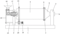
The invention relates to the technical field of ore grinding equipment, and discloses a wet overflow ball mill which comprises a bottom plate and a cylinder body, wherein a first base and a second base are fixedly arranged on the upper side of the bottom plate; one side of the first base is provided with a feeding assembly which comprises a transverse pipe, a vertical pipe and a feeding hopper, one end of the transverse pipe extends into the cylinder, the top of the other end of the transverse pipe is communicated with the vertical pipe, the feeding hopper is fixedly installed at the top of the vertical pipe, a short shaft is rotatably installed in the vertical pipe in the horizontal direction, a plurality of groups of blades are fixedly installed on the outer side of the short shaft, and a packing auger is rotatably installed in the transverse pipe; the ore can be accurately conveyed into the barrel, and blockage caused by accumulation is avoided.
Description
The technical field is as follows:
the invention relates to the technical field of ore grinding equipment, in particular to a wet overflow ball mill.
Background art:
the ball mill is a key device for crushing materials after the materials are crushed, is widely applied to production industries of cement, silicate products, novel building materials, refractory materials, chemical fertilizers, nonferrous metal mineral separation, glass ceramics and the like, carries out dry-type or wet-type grinding on various ores and other grindable materials, is suitable for grinding various ores and other materials, is widely applied to industries of mineral separation, building materials, chemical industry and the like, can be divided into a dry-type grinding mode and a wet-type grinding mode, and can be divided into a lattice type grinding mode and an overflow type grinding mode according to different ore discharge modes.
Compared with a grate ball mill and an overflow ball mill, the overflow ball mill has longer time for grinding ores in the working process, and the ores can be ground more fully in the machine body. The produced grinding ore product has finer granularity, and the production capacity per unit volume is slightly smaller than that of a grate-type ball mill of the same model. The overflow ball mill is generally applied to secondary grinding operation.
The current wet-type overflow ball mill can take place blocking phenomenon often in the feeding process, needs the manual work to clear stifled, has not only reduced work efficiency, and because the ball mill size is great, the workman need scramble highly moreover, increases workman injured's risk.
The invention content is as follows:
in view of the problems of the prior art, an object of the present invention is to provide a wet overflow ball mill.
The technical problem to be solved by the invention is realized by adopting the following technical scheme: a wet overflow ball mill comprises a bottom plate and a cylinder body, wherein a first base and a second base are fixedly mounted on the upper side of the bottom plate, an opening is formed in one end of the cylinder body, a first supporting body is fixedly mounted at the other end of the cylinder body, the first supporting body penetrates through the first base and is in rotary connection with the first base, a connecting ring is fixedly mounted at one end, close to the opening, of the cylinder body, one side of the connecting ring is fixedly connected with a discharging table through a bolt, an integrally formed second supporting body is arranged at one end, far away from the cylinder body, of the discharging table, and the second supporting body penetrates through the second base and is in rotary connection with the second base;
first base is kept away from barrel one side and is equipped with the feeding subassembly, including violently managing, standpipe and feeder hopper, violently manage one end and run through in first supporter extends to the barrel, and other end top intercommunication has the standpipe, standpipe top fixed mounting has the feeder hopper, the inside horizontal direction of standpipe rotates and installs the minor axis, and minor axis outside fixed mounting has a plurality of groups blade, violently manage the internal rotation and install the auger.
Preferably, a gear ring is fixedly mounted on the outer side of the cylinder, a motor is fixedly mounted on the upper side of the bottom plate, a gear is fixedly connected to an output shaft of the motor, and the gear is meshed with the gear ring.
Preferably, the cross section of the inner cavity of the transverse tube is circular, and the cross section of the inner cavity of the vertical tube is square.
Preferably, a plurality of groups of mill lining plates are distributed on the inner wall of the barrel in an annular mode, a rotating rod is arranged inside the barrel and fixedly connected with the barrel through a supporting rod, one end of the rotating rod penetrates through the barrel and extends into the transverse pipe, and a packing auger is fixedly mounted on the rotating rod and located inside the transverse pipe.
Preferably, the vertical pipe is internally and obliquely provided with a stopping plate, one end, away from the transverse pipe, of the stopping plate is a higher end and is hinged to the side wall of the vertical pipe through a pin shaft, the pin shaft is sleeved with a torsion spring, one end of the torsion spring is fixedly connected with the pin shaft, the other end of the torsion spring is fixedly connected with the side wall of the vertical pipe, the bottom of the stopping plate is fixedly provided with a boss, the left end of the rotating rod is fixedly provided with a cam, and the cam is in sliding connection with the boss.
Preferably, the inside horizontal direction of standpipe rotates and installs the minor axis, and the minor axis outside fixed mounting has a plurality of groups of blades, the blade distributes around the minor axis annular, minor axis one end is run through the standpipe fixed mounting and is had first band pulley, the pivot left end is run through first base fixed mounting and is had the second band pulley, pass through belt transmission connection between first band pulley and the second band pulley.
Preferably, the joint of the first support body and the first base and the joint of the second support body and the second base are both provided with bearings.
Preferably, ejection of compact platform and apron integral type design, be equipped with the water conservancy diversion hole on the apron, the slope is equipped with the blown down tank on the ejection of compact platform, and the inclination of blown down tank is crescent around by the middle part, water conservancy diversion hole and blown down tank intercommunication.
Preferably, a sealing gasket is arranged at the joint of the cover plate and the connecting ring.
Preferably, a plurality of groups of reinforcing rods are fixedly arranged between the vertical pipe and the first base.
Compared with the prior art, the invention has the beneficial effects that:
according to the invention, the motor drives the gear to rotate, and then the gear ring is meshed with the transmission gear to drive the barrel to rotate, the rotating shaft drives the short shaft to rotate through the transmission action of the belt while rotating, so that the blades rotate along with the short shaft, ore in the feeding hopper can be fed intermittently and continuously, meanwhile, the barrel drives the rotating rod to synchronously rotate, the rotating rod drives the auger to rotate, so that the ore falling at the end part of the transverse pipe can be accurately conveyed into the barrel, and blockage caused by accumulation is avoided.
According to the ball mill, the rotating rod drives the packing auger to rotate and convey, and meanwhile drives the cam at the end part to rotate, the cam is matched with the material blocking plate hinged to the side wall of the vertical pipe, so that the material blocking plate can swing around the pin shaft at a certain angle, the discharging from the vertical pipe to the horizontal pipe is adjusted according to the rotating and conveying speed of the packing auger, the stacking phenomenon is avoided while the feeding is continuously conveyed through the arrangement of two stages of discharging devices in the vertical pipe, and the working efficiency of the ball mill is improved.
Description of the drawings:
in order to more clearly illustrate the technical solutions in the embodiments of the present invention, the drawings needed to be used in the description of the embodiments are briefly introduced below, and it is obvious that the drawings in the following description are only some embodiments of the present invention, and for those skilled in the art, other drawings can be obtained according to the drawings without creative efforts;
FIG. 1 is a schematic view of the overall structure of the present invention;
FIG. 2 is a schematic view of the internal structure of the cross tube of the present invention;
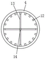
FIG. 3 is a side view of the support rod of the present invention;
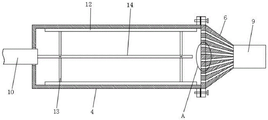
FIG. 4 is a schematic view of the internal structure of the cartridge according to the present invention;
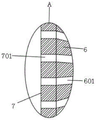
FIG. 5 is an enlarged view of a portion of FIG. 4A according to the present invention;
wherein: 1. a base plate; 2. a first base; 3. a second base; 4. a barrel; 5. a first support; 6. a discharging table; 601. a discharge chute; 7. a cover plate; 701. a flow guide hole; 8. a connecting ring; 9. a second support; 10. a transverse tube; 11. a vertical tube; 12. a mill lining plate; 13. a support bar; 14. a rotating rod; 15. a packing auger; 16. a feed hopper; 17. a bearing; 18. a motor; 19. a rotating shaft; 20. a gear; 21. a ring gear; 22. a belt; 23. a cam; 24. a material stopping plate; 25. a boss; 26. a reinforcing bar; 27. a blade.
The specific implementation mode is as follows:
in order to make the technical means, the creation characteristics, the achievement purposes and the effects of the invention easy to understand, the invention is further explained below by combining the specific drawings.
Example 1:
as shown in fig. 1-5, a wet overflow ball mill comprises a bottom plate 1 and a cylinder 4, wherein a first base 2 and a second base 3 are fixedly installed on the upper side of the bottom plate 1, an opening is formed at one end of the cylinder 4, a first support 5 is fixedly installed at the other end of the cylinder 4, the first support 5 penetrates through the first base 2 and is rotatably connected with the first base, a connecting ring 8 is fixedly installed at one end of the cylinder 4 close to the opening, a discharging table 6 is fixedly connected to one side of the connecting ring 8 through a bolt, an integrally formed second support 9 is arranged at one end of the discharging table 6 far away from the cylinder 4, and the second support 9 penetrates through the second base 3 and is rotatably connected with the second base;
The cross section of the inner cavity of the transverse pipe 10 is circular, and the cross section of the inner cavity of the vertical pipe 11 is square.
A plurality of groups of mill lining plates 12 are distributed on the inner wall of the barrel body 4 in an annular mode, a rotating rod 14 is arranged inside the barrel body 4, the rotating rod 14 is fixedly connected with the barrel body 4 through a supporting rod 13, one end of the rotating rod 14 penetrates through the barrel body 4 and extends into the transverse pipe 10, a packing auger 15 is arranged inside the transverse pipe 10 and fixedly mounted on the rotating rod 14.
Specifically, when fluid materials are fed, the bent pipe cannot greatly influence the feeding process, but in the feeding process of ores, due to the fact that the included angle of the conveying pipeline forms sudden change of a conveying section, accumulation can be caused at the sudden change position, and the blockage phenomenon can be caused in a long time.
Example 2:
on the basis of embodiment 1, as shown in fig. 2, the same parts are not described again, but the differences are; the improved vertical pipe structure is characterized in that a material stopping plate 24 is obliquely arranged inside the vertical pipe 11, one end, far away from the transverse pipe 10, of the material stopping plate 24 is a higher end and is hinged to the side wall of the vertical pipe 11 through a pin shaft, a torsion spring is sleeved on the pin shaft, one end of the torsion spring is fixedly connected with the pin shaft, the other end of the torsion spring is fixedly connected with the side wall of the vertical pipe 11, a boss 25 is fixedly installed at the bottom of the material stopping plate 24, a cam 23 is fixedly installed at the left end of the rotating rod 14, and the cam 23 is in sliding connection with the boss 25.
The inside horizontal direction of standpipe 11 rotates and installs the minor axis, and the minor axis outside fixed mounting has a plurality of groups of blades 27, blade 27 distributes around the minor axis ring, minor axis one end is run through standpipe 11 fixed mounting and is had first band pulley, the pivot 19 left end is run through first base 2 fixed mounting and is had the second band pulley, pass through belt 22 transmission connection between first band pulley and the second band pulley.
It is specific, barrel 4 drives mill welt 12 rotatory, it is rotatory to drive bull stick 14 through bracing piece 13, bull stick 14 drives 15 rotatory transport of auger and drives the cam 23 of tip simultaneously and rotate, cam 23 makes the flitch 24 can carry out the swing of certain angle around the round pin axle with the cooperation between the flitch 24 and the torsional spring that articulates on the 11 lateral walls of standpipe, thereby follow auger 15 rotatory conveying speed and adjust standpipe 11 to the unloading in violently managing 10, can not cause the phenomenon of piling up when guaranteeing to continuously carry the feeding through setting up of two-stage unloader in standpipe 11, thereby improve the work efficiency of ball mill.
And bearings 17 are arranged at the joints of the first support body 5 and the first base 2 and the joints of the second support body 9 and the second base 3.
Ejection of compact platform 6 and 7 integral type designs of apron, be equipped with water conservancy diversion hole 701 on the apron 7, slope on the ejection of compact platform 6 is equipped with blown down tank 601, and the inclination of blown down tank 601 is crescent around by the middle part, water conservancy diversion hole 701 and blown down tank 601 intercommunication.
And a sealing gasket is arranged at the joint of the cover plate 7 and the connecting ring 8.
A plurality of sets of reinforcing rods 26 are fixedly arranged between the vertical pipe 11 and the first base 2.
Specifically, the arrangement of the bearing 17 reduces the friction force in the rotation process, and simultaneously can play a role of radial support for the cylinder 4, the invention is convenient for regular maintenance and overhaul of parts in the cylinder 4 through the detachable design between the cover plate 7 and the connecting ring 8, the cover plate 7 is provided with the flow guide holes 701, the discharging platform 6 is provided with the discharging groove 601 in an inclined manner, the inclined angle of the discharging groove 601 is gradually increased from the middle part to the periphery, the flow guide holes 701 are communicated with the discharging groove 601, so that the ore pulp in the cylinder 4 is better discharged from the second support body 9, when the ore pulp in the cylinder 4 is less, the flow guide holes 701 and the discharging groove 601 at the bottom also contain part of ore pulp, the part of ore pulp is driven to rise along with the rotation of the cylinder 4, because of the unique inclined angle of the discharging groove 601, the ore pulp in the discharging groove 601 flows to the right side in an inclined manner, thereby being beneficial to the discharge of the ore pulp, the second supporting body 9 and the first supporting body 5 are similar in structure and adopt a hollow structure design, and only a spiral guide structure is arranged inside the second supporting body 9, so that ore pulp is discharged more favorably.
It is noted that, herein, relational terms such as first and second, and the like may be used solely to distinguish one entity or action from another entity or action without necessarily requiring or implying any actual such relationship or order between such entities or actions. Also, the terms "comprises," "comprising," or any other variation thereof, are intended to cover a non-exclusive inclusion, such that a process, method, article, or apparatus that comprises a list of elements does not include only those elements but may include other elements not expressly listed or inherent to such process, method, article, or apparatus. Without further limitation, an element defined by the phrase "comprising an … …" does not exclude the presence of other identical elements in a process, method, article, or apparatus that comprises the element.
The foregoing shows and describes the general principles and broad features of the present invention and advantages thereof. It will be understood by those skilled in the art that the present invention is not limited to the embodiments described above, which are described in the specification and illustrated only to illustrate the principle of the present invention, but that various changes and modifications may be made therein without departing from the spirit and scope of the present invention, which fall within the scope of the invention as claimed. The scope of the invention is defined by the appended claims and equivalents thereof.
Claims (9)
1. A wet overflow ball mill is characterized in that: the device comprises a bottom plate (1) and a barrel (4), wherein a first base (2) and a second base (3) are fixedly mounted on the upper side of the bottom plate (1), an opening is formed in one end of the barrel (4), a first supporting body (5) is fixedly mounted on the other end of the barrel (4), the first supporting body (5) penetrates through the first base (2) and is rotatably connected with the first base, a connecting ring (8) is fixedly mounted at one end, close to the opening, of the barrel (4), one side of the connecting ring (8) is fixedly connected with a discharging table (6) through a bolt, an integrally formed second supporting body (9) is arranged at one end, far away from the barrel (4), of the discharging table (6), and the second supporting body (9) penetrates through the second base (3) and is rotatably connected with the second base;
barrel (4) one side is kept away from in first base (2) is equipped with the feeding subassembly, including violently managing (10), standpipe (11) and feeder hopper (16), violently manage (10) one end and run through in first supporter (5) extends to barrel (4), other end top intercommunication has standpipe (11), standpipe (11) top fixed mounting has feeder hopper (16), standpipe (11) inside horizontal direction rotates installs the minor axis, minor axis outside fixed mounting has a plurality of blades of group (27), violently manage (10) internal rotation and install auger (15).
2. A wet overflow ball mill according to claim 1, wherein: the utility model discloses a motor, including barrel (4), bottom plate (1), output shaft, gear (20) and ring gear (21), barrel (4) outside fixed mounting has ring gear (21), bottom plate (1) upside fixed mounting has motor (18), the output shaft rigid coupling of motor (18), gear (20) and ring gear (21) meshing are connected.
3. A wet overflow ball mill according to claim 1, wherein: the utility model discloses a barrel, including barrel (4), barrel (4) inner wall, annular distribution has a plurality of groups mill welt (12), barrel (4) inside is equipped with bull stick (14), bull stick (14) are through bracing piece (13) and barrel (4) fixed connection, bull stick (14) one end is run through barrel (4) and is extended to violently inside pipe (10), is located and violently manages (10) inside fixed mounting has auger (15) on bull stick (14).
4. A wet overflow ball mill according to claim 3, wherein: standpipe (11) inside slope is equipped with material stopping plate (24), material stopping plate (24) are kept away from violently pipe (10) one end and are articulated through the round pin axle for higher end and with standpipe (11) lateral wall, the epaxial torsional spring that has cup jointed of round pin, torsional spring one end and round pin axle rigid coupling, the other end and standpipe (11) lateral wall rigid coupling, material stopping plate (24) bottom fixed mounting has boss (25), bull stick (14) left end fixed mounting has cam (23), cam (23) and boss (25) sliding connection.
5. A wet overflow type ball mill according to claim 1 or 4, wherein: the blades (27) are distributed in an annular mode around a short shaft, a first belt wheel is fixedly installed at one end of the short shaft in a penetrating mode through the vertical pipe (11), a second belt wheel is fixedly installed at the left end of the rotating shaft (19) in a penetrating mode through the first base (2), and the first belt wheel is in transmission connection with the second belt wheel through a belt (22).
6. A wet overflow ball mill according to claim 1, wherein: and bearings (17) are arranged at the joint of the first support body (5) and the first base (2) and the joint of the second support body (9) and the second base (3).
7. A wet overflow ball mill according to claim 1, wherein: discharge table (6) and apron (7) integral type design, be equipped with water conservancy diversion hole (701) on apron (7), slope on discharge table (6) is equipped with blown down tank (601), and the inclination of blown down tank (601) is by the middle part to crescent around, water conservancy diversion hole (701) and blown down tank (601) intercommunication.
8. A wet overflow ball mill according to claim 7, wherein: and a sealing gasket is arranged at the joint of the cover plate (7) and the connecting ring (8).
9. A wet overflow ball mill according to claim 1, wherein: and a plurality of groups of reinforcing rods (26) are fixedly arranged between the vertical pipe (11) and the first base (2).
Priority Applications (1)
| Application Number | Priority Date | Filing Date | Title |
|---|---|---|---|
| CN202210310225.1A CN114522775A (en) | 2022-03-28 | 2022-03-28 | Wet overflow ball mill |
Applications Claiming Priority (1)
| Application Number | Priority Date | Filing Date | Title |
|---|---|---|---|
| CN202210310225.1A CN114522775A (en) | 2022-03-28 | 2022-03-28 | Wet overflow ball mill |
Publications (1)
| Publication Number | Publication Date |
|---|---|
| CN114522775A true CN114522775A (en) | 2022-05-24 |
Family
ID=81627114
Family Applications (1)
| Application Number | Title | Priority Date | Filing Date |
|---|---|---|---|
| CN202210310225.1A Pending CN114522775A (en) | 2022-03-28 | 2022-03-28 | Wet overflow ball mill |
Country Status (1)
| Country | Link |
|---|---|
| CN (1) | CN114522775A (en) |
Cited By (1)
| Publication number | Priority date | Publication date | Assignee | Title |
|---|---|---|---|---|
| CN114918010A (en) * | 2022-06-08 | 2022-08-19 | 赣州嘉通新材料有限公司 | Neodymium iron boron powder preparation facilities |
Citations (16)
| Publication number | Priority date | Publication date | Assignee | Title |
|---|---|---|---|---|
| CN204057034U (en) * | 2014-09-19 | 2014-12-31 | 成都正大有限公司 | Puffing material air sealer device |
| CN205761521U (en) * | 2016-05-24 | 2016-12-07 | 牟伟才 | A kind of disposable medical instrument reducing mechanism |
| CN206008879U (en) * | 2016-08-11 | 2017-03-15 | 元阳县华西黄金有限公司 | A kind of novel mineral wet overflow type ball mill |
| CN207733642U (en) * | 2017-12-23 | 2018-08-17 | 吉林省农业科学院 | A kind of fermented stalk feed mixing machine liquid auto spraying injection device |
| CN108636285A (en) * | 2018-07-25 | 2018-10-12 | 长兴九鑫环保科技有限公司 | A kind of biomass fuel granulation processing unit (plant) |
| CN208032722U (en) * | 2017-12-27 | 2018-11-02 | 泰顺县添越家庭农场 | A kind of feed stuff reducing device based on rotation flabellum water conservancy diversion charging |
| CN208182230U (en) * | 2018-04-11 | 2018-12-04 | 湖北金果茶业股份有限公司 | A kind of fresh leaf flowmeter of adjustable speed |
| CN210463908U (en) * | 2019-07-31 | 2020-05-05 | 安徽华金味食品有限公司 | Drying device for yeast production |
| CN210841413U (en) * | 2019-10-18 | 2020-06-26 | 青岛百峰盛源食品有限公司 | Bean product processing production control system |
| CN210876173U (en) * | 2019-07-26 | 2020-06-30 | 漳州理工职业学院 | Vibration ash-raising separator |
| CN213967585U (en) * | 2020-09-04 | 2021-08-17 | 河南众和蓝图新型建材有限公司 | Ore conveying equipment convenient to screen |
| CN213996113U (en) * | 2020-08-25 | 2021-08-20 | 武钢资源集团鄂州球团有限公司 | Energy-saving ore ball mill of wet or dry |
| CN214234295U (en) * | 2021-01-11 | 2021-09-21 | 博爱金隅水泥有限公司 | Efficient cement mill |
| CN214288555U (en) * | 2020-08-28 | 2021-09-28 | 丹东市鑫祥泰矿山设备有限公司 | Ore discharging device of overflow type ball mill |
| CN214811385U (en) * | 2020-12-30 | 2021-11-23 | 上海奇迎高分子材料有限公司 | Formaldehyde resin produces ball mill |
| WO2021248233A1 (en) * | 2020-06-11 | 2021-12-16 | Starkey & Associates Inc. | Lab-scale continuous semi-autogenous (sag) grinding mill |
-
2022
- 2022-03-28 CN CN202210310225.1A patent/CN114522775A/en active Pending
Patent Citations (16)
| Publication number | Priority date | Publication date | Assignee | Title |
|---|---|---|---|---|
| CN204057034U (en) * | 2014-09-19 | 2014-12-31 | 成都正大有限公司 | Puffing material air sealer device |
| CN205761521U (en) * | 2016-05-24 | 2016-12-07 | 牟伟才 | A kind of disposable medical instrument reducing mechanism |
| CN206008879U (en) * | 2016-08-11 | 2017-03-15 | 元阳县华西黄金有限公司 | A kind of novel mineral wet overflow type ball mill |
| CN207733642U (en) * | 2017-12-23 | 2018-08-17 | 吉林省农业科学院 | A kind of fermented stalk feed mixing machine liquid auto spraying injection device |
| CN208032722U (en) * | 2017-12-27 | 2018-11-02 | 泰顺县添越家庭农场 | A kind of feed stuff reducing device based on rotation flabellum water conservancy diversion charging |
| CN208182230U (en) * | 2018-04-11 | 2018-12-04 | 湖北金果茶业股份有限公司 | A kind of fresh leaf flowmeter of adjustable speed |
| CN108636285A (en) * | 2018-07-25 | 2018-10-12 | 长兴九鑫环保科技有限公司 | A kind of biomass fuel granulation processing unit (plant) |
| CN210876173U (en) * | 2019-07-26 | 2020-06-30 | 漳州理工职业学院 | Vibration ash-raising separator |
| CN210463908U (en) * | 2019-07-31 | 2020-05-05 | 安徽华金味食品有限公司 | Drying device for yeast production |
| CN210841413U (en) * | 2019-10-18 | 2020-06-26 | 青岛百峰盛源食品有限公司 | Bean product processing production control system |
| WO2021248233A1 (en) * | 2020-06-11 | 2021-12-16 | Starkey & Associates Inc. | Lab-scale continuous semi-autogenous (sag) grinding mill |
| CN213996113U (en) * | 2020-08-25 | 2021-08-20 | 武钢资源集团鄂州球团有限公司 | Energy-saving ore ball mill of wet or dry |
| CN214288555U (en) * | 2020-08-28 | 2021-09-28 | 丹东市鑫祥泰矿山设备有限公司 | Ore discharging device of overflow type ball mill |
| CN213967585U (en) * | 2020-09-04 | 2021-08-17 | 河南众和蓝图新型建材有限公司 | Ore conveying equipment convenient to screen |
| CN214811385U (en) * | 2020-12-30 | 2021-11-23 | 上海奇迎高分子材料有限公司 | Formaldehyde resin produces ball mill |
| CN214234295U (en) * | 2021-01-11 | 2021-09-21 | 博爱金隅水泥有限公司 | Efficient cement mill |
Cited By (2)
| Publication number | Priority date | Publication date | Assignee | Title |
|---|---|---|---|---|
| CN114918010A (en) * | 2022-06-08 | 2022-08-19 | 赣州嘉通新材料有限公司 | Neodymium iron boron powder preparation facilities |
| CN114918010B (en) * | 2022-06-08 | 2024-02-23 | 赣州嘉通新材料有限公司 | Neodymium iron boron powder preparation facilities |
Similar Documents
| Publication | Publication Date | Title |
|---|---|---|
| CN201494822U (en) | Storage bin capable of automatically discharging | |
| CN210279281U (en) | Conveying equipment for refractory material production raw materials | |
| CN208070868U (en) | The feeding structure of cement bin | |
| CN101559297B (en) | Method and device for forced discharge of high-concentration underflow of a thickener | |
| CN110882765A (en) | Grinding machine with high grinding capacity | |
| CN114522775A (en) | Wet overflow ball mill | |
| CN116588604B (en) | Screw conveyer capable of realizing quick feed and discharge | |
| CN212952154U (en) | Dry-mixed mortar unloader | |
| CN218908429U (en) | Raw material bin capable of preventing material bridging | |
| CN216756742U (en) | Wear-resisting pyrophyllite mill charge-in pipeline that easily dredges | |
| CN211870807U (en) | Lime stone unloading conveying equipment | |
| CN212711266U (en) | Screw conveyer | |
| CN213409016U (en) | Powder returning device of auger shaft | |
| CN209080979U (en) | A kind of quantitative conveyor screw conveyer of concrete mixing plant | |
| CN114558520A (en) | Automatic chemical production mechanical equipment of pay-off | |
| CN211921367U (en) | A screw conveyer for fertilizer fermentation equipment material loading | |
| CN220466931U (en) | Colliery conveyer | |
| KR20090099962A (en) | Exhausting device for silo | |
| CN209866292U (en) | Slay grinds spiral feeding unit immediately | |
| CN220744281U (en) | Bucket type lifting device for cement | |
| CN219540477U (en) | Material crushing system of drying equipment | |
| CN205555595U (en) | Cascaded spiral transportation crushing equipment | |
| CN216637843U (en) | Single-tube rotary conveyor | |
| CN214525830U (en) | Material bin and concrete material system | |
| CN219524956U (en) | Conveyor hopper with arch breaking device |
Legal Events
| Date | Code | Title | Description |
|---|---|---|---|
| PB01 | Publication | ||
| PB01 | Publication | ||
| SE01 | Entry into force of request for substantive examination | ||
| SE01 | Entry into force of request for substantive examination |