CN114509362B - Hardness detection equipment is used in steel construction production based on it is spacing - Google Patents
Hardness detection equipment is used in steel construction production based on it is spacing Download PDFInfo
- Publication number
- CN114509362B CN114509362B CN202210407538.9A CN202210407538A CN114509362B CN 114509362 B CN114509362 B CN 114509362B CN 202210407538 A CN202210407538 A CN 202210407538A CN 114509362 B CN114509362 B CN 114509362B
- Authority
- CN
- China
- Prior art keywords
- workbench
- fixedly connected
- steel structure
- hardness
- screw
- Prior art date
- Legal status (The legal status is an assumption and is not a legal conclusion. Google has not performed a legal analysis and makes no representation as to the accuracy of the status listed.)
- Active
Links
Images


Classifications
-
- G—PHYSICS
- G01—MEASURING; TESTING
- G01N—INVESTIGATING OR ANALYSING MATERIALS BY DETERMINING THEIR CHEMICAL OR PHYSICAL PROPERTIES
- G01N3/00—Investigating strength properties of solid materials by application of mechanical stress
- G01N3/40—Investigating hardness or rebound hardness
-
- G—PHYSICS
- G01—MEASURING; TESTING
- G01M—TESTING STATIC OR DYNAMIC BALANCE OF MACHINES OR STRUCTURES; TESTING OF STRUCTURES OR APPARATUS, NOT OTHERWISE PROVIDED FOR
- G01M13/00—Testing of machine parts
-
- G—PHYSICS
- G01—MEASURING; TESTING
- G01N—INVESTIGATING OR ANALYSING MATERIALS BY DETERMINING THEIR CHEMICAL OR PHYSICAL PROPERTIES
- G01N3/00—Investigating strength properties of solid materials by application of mechanical stress
- G01N3/02—Details
-
- G—PHYSICS
- G01—MEASURING; TESTING
- G01N—INVESTIGATING OR ANALYSING MATERIALS BY DETERMINING THEIR CHEMICAL OR PHYSICAL PROPERTIES
- G01N3/00—Investigating strength properties of solid materials by application of mechanical stress
- G01N3/02—Details
- G01N3/04—Chucks
-
- G—PHYSICS
- G01—MEASURING; TESTING
- G01N—INVESTIGATING OR ANALYSING MATERIALS BY DETERMINING THEIR CHEMICAL OR PHYSICAL PROPERTIES
- G01N2203/00—Investigating strength properties of solid materials by application of mechanical stress
- G01N2203/0001—Type of application of the stress
- G01N2203/0003—Steady
-
- G—PHYSICS
- G01—MEASURING; TESTING
- G01N—INVESTIGATING OR ANALYSING MATERIALS BY DETERMINING THEIR CHEMICAL OR PHYSICAL PROPERTIES
- G01N2203/00—Investigating strength properties of solid materials by application of mechanical stress
- G01N2203/003—Generation of the force
- G01N2203/0042—Pneumatic or hydraulic means
- G01N2203/0048—Hydraulic means
-
- G—PHYSICS
- G01—MEASURING; TESTING
- G01N—INVESTIGATING OR ANALYSING MATERIALS BY DETERMINING THEIR CHEMICAL OR PHYSICAL PROPERTIES
- G01N2203/00—Investigating strength properties of solid materials by application of mechanical stress
- G01N2203/0058—Kind of property studied
- G01N2203/0076—Hardness, compressibility or resistance to crushing
-
- G—PHYSICS
- G01—MEASURING; TESTING
- G01N—INVESTIGATING OR ANALYSING MATERIALS BY DETERMINING THEIR CHEMICAL OR PHYSICAL PROPERTIES
- G01N2203/00—Investigating strength properties of solid materials by application of mechanical stress
- G01N2203/02—Details not specific for a particular testing method
- G01N2203/06—Indicating or recording means; Sensing means
- G01N2203/067—Parameter measured for estimating the property
- G01N2203/0676—Force, weight, load, energy, speed or acceleration
Abstract
The invention belongs to the technical field of hardness detection equipment, and particularly relates to limit-based hardness detection equipment for steel structure production, which comprises the following components in part by weight: a box body; the workbench is arranged inside the box body; the workbench is provided with a limiting assembly for fixing and limiting the steel structure; the workbench is also provided with a hardness detection assembly for detecting the hardness of the steel structure; the hardness detection assembly includes: the supporting column is rotatably connected with the workbench; one side above the supporting column is rotatably connected with an adjusting rod; the detection head is fixedly connected to one side of the adjusting rod; and the support column is also connected with a sliding sleeve in a sliding manner. According to the invention, the hardness detection assembly is arranged to detect the hardness of the steel structure, manual intervention is not required, the limiting assembly and the hardness detection assembly are combined, so that the device can automatically detect the steel structure, the operation is simple, and the practicability is stronger.
Description
Technical Field
The invention belongs to the technical field of hardness detection equipment, and particularly relates to limit-based hardness detection equipment for steel structure production.
Background
The hardness test is one of the important indexes for detecting the performance of the steel structure and is one of the fastest and most economical test methods, so the hardness test can become a common method for mechanical property tests, because the hardness test can reflect the difference of materials in chemical components, tissue structures and treatment processes and is often used as a supervision means to be applied to various industries, the hardness test can be used for researching the quality of the steel structure.
Hardness testing equipment is the special instrument that is used for measuring the surface hardness of coating, hardness testing meter divide into desk-top sclerometer, portable sclerometer is two kinds, desk-top sclerometer mainly is used for the laboratory to use, the advantage that has the high precision, portable sclerometer is used for machinery or permanent equipment part installed, high portability, portable sclerometer collects the portable sclerometer such as riches, brinell, rockwell in an organic whole, can realize the free conversion of multiple different hardness number, it needs artifical the seeking sclerometer to carry out the vexation procedure to have got rid of the sclerometer in the past, intelligent, the characteristics of accurate in the true sense have been realized.
Application number is CN 202011519882.4's chinese patent, it discloses a hardness detection equipment is used in steel construction production, the power distribution box comprises a box body, unable adjustment base, chamber door and handle, this hardness detection equipment is used in steel construction production can drive two splint removals of two-way threaded rod drive through the second motor, make two splint can press from both sides the steel construction clamp in the backup pad fixed, thereby make and to go up the steel construction shift position in the backup pad through splint, be convenient for align the position of steel construction with hardness detection component, need not the position of steel construction in the manual adjustment backup pad, make things convenient for hardness detection component to carry out hardness detection to the steel construction in the backup pad.
But the hardness test equipment is used in steel construction production that above-mentioned patent provided, can't in use carry out automatic hardness to the steel construction and detect, and detection achievement is comparatively loaded down with trivial details, is not suitable for using widely.
Disclosure of Invention
An embodiment of the present invention provides a steel structure production hardness detection device based on limiting to solve the above technical problems, and the steel structure production hardness detection device based on limiting includes:
a box body; the workbench is arranged inside the box body;
the workbench is provided with a limiting assembly for fixing and limiting the steel structure;
the workbench is also provided with a hardness detection assembly for detecting the hardness of the steel structure;
the hardness detection assembly includes:
the supporting column is rotatably connected with the workbench;
one side above the supporting column is rotatably connected with an adjusting rod; the detection head is fixedly connected to one side of the adjusting rod;
the support column is also connected with a sliding sleeve in a sliding manner;
the sliding sleeve is rotatably connected with a connecting rod, and the other side of the connecting rod is rotatably connected with an adjusting rod;
the sliding sleeve is also rotatably connected with a hydraulic telescopic rod, and the other side of the hydraulic telescopic rod is rotatably connected with the workbench;
and one side of the reset spring is fixedly connected with the support column, and the other side of the reset spring is fixedly connected with the sliding sleeve.
Further, the hardness detection assembly further includes: the auxiliary clamping block is fixedly connected with the supporting column, a square groove is further formed in the workbench, and the square groove is the same as the position of the screw plate in the horizontal direction.
Furthermore, the number of the limiting assemblies is two, and the two same limiting assemblies are symmetrically distributed on two sides of the workbench.
Further, spacing subassembly includes:
the sliding chute is arranged on the workbench; the sliding block is connected inside the sliding groove in a sliding mode;
the slider is connected with a clamping rod in a rotating mode, and the other side of the clamping rod is fixedly connected with a main clamping block.
Further, the spacing subassembly still includes:
the screw block is rotationally connected with the clamping rod; the screw block is connected inside the screw plate in a sliding manner;
a screw rod is also rotatably connected in the screw plate and is connected with the screw block through threads;
and a rotating handle is further arranged on one side of the screw rod, which is far away from the screw block.
Further, steel construction production is with hardness testing equipment still includes based on it is spacing:
and the rotating lifting assembly is arranged inside the box body and is used for rotating and lifting the workbench.
Further, the rotating and lifting assembly comprises:
the lifting motor is fixedly connected to the box body; the first bevel gear is fixedly connected to the output end of the lifting motor;
a second bevel gear meshed with the first bevel gear;
a lifting screw is fixedly connected to the second bevel gear; and a threaded sleeve in threaded connection with the lifting screw;
the upper part of the threaded sleeve is connected with the workbench through a bearing.
Furthermore, a support is rotatably connected below the lifting screw rod and is fixedly connected with the box body.
Further, the rotating and lifting assembly further comprises:
the rotating motor is fixedly connected with the box body; the first belt roller is fixedly connected to the output end of the rotating motor;
a belt is arranged on the outer side of the first belt roller; the second belt roller is connected to one side, far away from the first belt roller, of the belt;
the second belt roller is rotationally connected with the bracket;
and a telescopic rod is fixedly connected to one side of the upper part of the second belt roller, and the other side of the telescopic rod is fixedly connected with the workbench.
Furthermore, the number of the telescopic rods is two, and the two same telescopic rods are symmetrically distributed on two sides above the second belt roller.
In summary, the invention mainly has the following beneficial effects:
1. according to the limit-based hardness detection equipment for steel structure production, provided by the invention, the adjusting rod, the connecting rod and the supporting column are arranged to be matched, so that the adjusting rod can limit the steel structure in the steel structure production, and the device can detect the hardness of the steel structure.
2. Through setting up sliding sleeve, hydraulic telescoping rod and vice clamp splice for the device can carry on spacingly to the steel construction, avoids the steel construction to remove in hardness testing process, influences the accuracy of testing result.
3. Through setting up clamping bar and main clamp splice for the device can fix the steel construction spacing, and through the cooperation with spout and slider, makes the position of main clamp splice remove, thereby realizes spacing to the different positions of main clamp splice, further improves the spacing ability of device.
4. The two sets of limiting assemblies are arranged, so that the device can limit the two sides of the steel structure, and the steel structure is prevented from moving in the detection process to a greater extent.
5. Through the setting that rotates lifting unit for the workstation can go up and down, obtains better hardness and detects the height, and rotate lifting unit and adjust the pole cooperation, thereby make the main clamp splice can carry out automation spacingly to the steel construction, need not the human intervention operation, rotate lifting unit simultaneously and also make the workstation can rotate, further improve the detection range and the convenience of use of device to the steel construction.
In this embodiment, through setting up two sets of spacing subassemblies for the device can carry on spacingly to the both sides of steel construction, avoids the steel construction to remove in hardness testing process, and carries out hardness testing to the steel construction through hardness testing component, and need not artificial intervention, through combining spacing subassembly and hardness testing component, thereby makes the device can carry out automated inspection to the steel construction, and easy operation, and the practicality is stronger.
Drawings
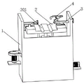
FIG. 1 is a schematic structural diagram of a hardness detection device for steel structure production based on limiting provided by an embodiment of the invention;
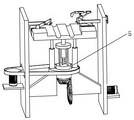
FIG. 2 is a schematic view of an internal structure of a box body in the limit-based hardness detection equipment for steel structure production according to the embodiment of the invention;
FIG. 3 is a schematic diagram of the positions of a chute and a screw plate in the hardness detection equipment for steel structure production based on limiting provided by the embodiment of the invention;
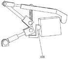
FIG. 4 is a schematic structural diagram of a limiting assembly in the hardness detection equipment for steel structure production based on limiting provided by the embodiment of the invention;
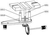
FIG. 5 is a schematic structural view of a hardness detection assembly in the limit-based hardness detection equipment for steel structure production provided by the embodiment of the invention;
FIG. 6 is a schematic view of clamping of an auxiliary clamp block in the hardness detection equipment for steel structure production based on limiting provided by the embodiment of the invention;
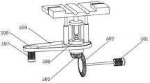
FIG. 7 is a schematic structural view of a rotary lifting assembly in the hardness detection equipment for steel structure production based on limiting provided by the embodiment of the invention;
fig. 8 is a schematic connection diagram of a second belt roller and a telescopic rod in the limit-based hardness detection device for steel structure production provided by the embodiment of the invention.
In the drawings: 1. a box body; 2. a work table; 201. a limiting groove; 3. a limiting component; 301. a chute; 302. a slider; 303. a clamping bar; 304. a main clamping block; 305. a screw block; 306. a screw plate; 307. a screw; 308. turning a handle; 4. a hardness detection assembly; 401. a support pillar; 402. adjusting a rod; 403. a detection head; 404. a sliding sleeve; 405. a connecting rod; 406. a hydraulic telescopic rod; 407. a return spring; 408. an auxiliary clamping block; 409. a square groove; 5. rotating the lifting assembly; 501. a lifting motor; 502. a first bevel gear; 503. a second bevel gear; 504. a lifting screw; 505. a threaded sleeve; 506. a support; 507. rotating the motor; 508. a first belt roller; 509. a belt; 5010. a second belt roller; 5011. a telescopic rod.
Detailed Description
In order to make the objects, technical solutions and advantages of the present invention more apparent, the present invention is described in further detail below with reference to the accompanying drawings and embodiments. It should be understood that the specific embodiments described herein are merely illustrative of the invention and are not intended to limit the invention.
Specific implementations of the present invention are described in detail below with reference to specific embodiments.
Referring to fig. 1 and 2, in the hardness detection apparatus for steel structure production based on limiting according to an embodiment of the present invention, the hardness detection apparatus for steel structure production based on limiting includes:
a box body 1; and a working table 2 arranged inside the box body 1;
the workbench 2 is provided with a limiting component 3 for fixing and limiting a steel structure;
the workbench 2 is also provided with a hardness detection assembly 4 for detecting the hardness of the steel structure;
the hardness detection unit 4 includes:
the supporting column 401 is rotatably connected with the workbench 2;
an adjusting rod 402 is rotatably connected to one side above the supporting column 401; and a detection head 403 fixedly connected to one side of the adjustment lever 402;
a sliding sleeve 404 is further connected to the supporting column 401 in a sliding manner;
the sliding sleeve 404 is rotatably connected with a connecting rod 405, and the other side of the connecting rod 405 is rotatably connected with the adjusting rod 402;
the sliding sleeve 404 is also rotatably connected with a hydraulic telescopic rod 406, and the other side of the hydraulic telescopic rod 406 is rotatably connected with the workbench 2;
and one side of the return spring 407 is fixedly connected with the supporting column 401, and the other side of the return spring 407 is fixedly connected with the sliding sleeve 404.
In the embodiment of the invention, the shape and the size of the box body 1 are not limited, wherein the size of the box body 1 can be determined according to the size of the hardness detection assembly 4 in the box body 1, meanwhile, the box body 1 can be in a cabinet shape or a box shape, the specific shape of the box body can also be determined according to actual use requirements, and when the box body 1 needs to be moved frequently, universal wheels can be additionally arranged on the bottom of the box body 1, so that the box body 1 can be conveniently used in different scenes.
In this embodiment, the top of the working table 2 is also provided with a limiting groove 201, and the steel structure product is placed, so that the primary limiting effect is achieved.
In this embodiment, the position of the hardness detection assembly 4 is not limited, and an air cylinder is also disposed on the hardness detection assembly 4, so that the hardness detection assembly 4 can move on the workbench 2, and hardness detection of different positions of the steel structure can be achieved, in the hardness detection assembly 4, the support column 401 is rotatably connected above the workbench 2, the support column 401 is sequentially sleeved with a sliding sleeve 404 and a return spring 407, the upper side of the support column 401 is rotatably connected with an adjusting rod 402, one side of the adjusting rod 402 is fixedly connected with a detection head 403, the detection head 403 can be a pressure sensor, when the detection head 403 extrudes the steel structure to cause deformation, pressure data at the moment can be recorded, the other side of the adjusting rod 402 is rotatably connected with a connecting rod 405, the other side of the connecting rod 405 is rotatably connected with the sliding sleeve 404, when the sliding sleeve 404 moves upwards, the adjusting rod 402 can rotate with the contact position of the support column 401 as a fulcrum by using a similar lever principle, the adjusting rod 402 and one side of the connecting rod 405 are tilted, one side of the detecting head 403 moves downwards, so that the extrusion of a steel structure is completed, and the hydraulic telescopic rod 406 can improve the power for the movement of the sliding sleeve 404.
In actual use, when hydraulic telescoping rod 406 extends, the support column 401 inclines at this moment, simultaneously the sliding sleeve 404 is also on support column 401, upward movement, when the sliding sleeve 404 moves upward, reset spring 407 extrudes and contracts, simultaneously connecting rod 405 will adjust one side perk of pole 402, thereby make detection head 403 one side move down, thereby accomplish the hardness detection of steel structure product, when hydraulic telescoping rod 406 contracts, can make support column 401 reset or reverse direction slope, conversely, sliding sleeve 404 is on support column 401, downward movement, connecting rod 405 will adjust one side of pole 402 right, detect the perk of head 403 one side, thereby release steel structure product, accomplish the operation, wherein extrude the steel structure when detecting head 403, until the steel structure takes place to warp, record this moment and detect the data on the head 403, accomplish the detection.
In an embodiment of the present invention, referring to fig. 5 and 6, the hardness testing apparatus further includes: the auxiliary clamping block 408 is fixedly connected with the supporting column 401, a square groove 409 is further formed in the workbench 2, and the square groove 409 is the same as the screw plate 306 in position in the horizontal direction.
In this embodiment, lie in the vice clamp splice 408 of fixedly connected with in the top of workstation 2 on support column 401, when support column 401 slope, can make vice clamp splice 408 take place the slope, assist the steel construction spacing, still be equipped with square groove 409 on the workstation 2, the setting of square groove 409 can make spiral shell board 306 when removing, can not blockked by workstation 2, influences the removal of workstation 2.
In an embodiment of the present invention, referring to fig. 1, the number of the limiting assemblies 3 is two, and two identical limiting assemblies 3 are symmetrically distributed on two sides of the worktable 2.
In this embodiment, 3 symmetric distribution of spacing subassembly are in 2 both sides of workstation to can carry on spacingly to the both ends of steel construction, avoid the steel construction to remove in hardness detection, improve the accuracy that hardness detected.
In an embodiment of the present invention, referring to fig. 3 and 4, the limiting assembly 3 includes:
the sliding chute 301 is arranged on the workbench 2; and a slider 302 slidably coupled inside the chute 301;
the slide block 302 is rotatably connected with a clamping rod 303, and the other side of the clamping rod 303 is fixedly connected with a main clamping block 304.
In the embodiment of the present invention, the sliding groove 301 is opened on the working platform 2, the sliding block 302 is slidably connected to the inside of the sliding groove 301, the sliding block 302 can easily move inside the sliding groove 301, and the size and shape of the main clamping block 304 are not limited, and the shape of the main clamping block 304 is determined according to the shape of the actual steel structure product.
In an embodiment of the present invention, referring to fig. 4, the position limiting assembly 3 further includes:
the screw block 305 is rotatably connected with the clamping rod 303; the screw block 305 is connected inside the screw plate 306 in a sliding way;
a screw 307 is rotatably connected in the screw plate 306, and the screw 307 is in threaded connection with the screw block 305;
a rotating handle 308 is arranged on one side of the screw 307 far away from the screw block 305.
In this embodiment, the screw plate 306 is fixedly connected to the inner side wall of the box body 1, the screw block 305 is slidably connected to the inner side of the screw plate 306, the screw 307 is further screwed to the inner side of the screw block 305, the screw 307 is rotatably connected to the screw plate 306, and meanwhile, the screw block 305 is also rotatably connected to the clamping rod 303.
In actual use, the screw plate 306 and the screw block 305 are fixed and cannot move, when the workbench 2 moves upwards, the sliding block 302 is driven to move upwards, at the moment, the middle position of the clamping rod 303 is fixed, one side of the clamping rod 303, which is connected with the sliding block 302, also moves upwards, the clamping rod 303 is driven to rotate, one side of the main clamping block 304 on the clamping rod 303 moves downwards, the main clamping block 304 is driven to extrude and limit the steel structure, when the steel structures at different positions or with different sizes need to be limited, the rotating handle 308 can be rotated, the screw 307 is driven to rotate, the screw block 305 is driven to move inside the screw plate 306, when the screw block 305 moves towards the rotating handle 308, the screw block 305 simultaneously drives the clamping rod 303 and the main clamping block 304 to move simultaneously, the reverse operation is realized, and the limitation on the steel structure can be relieved.
In an embodiment of the present invention, referring to fig. 2, the apparatus for detecting hardness in steel structure production based on position limitation further includes:
and the rotating lifting assembly 5 is arranged inside the box body 1 and is used for rotatably lifting the workbench 2.
In this embodiment, the setting of rotating lifting unit 5 can make workstation 2 go up and down to realize the automatic centre gripping of main clamp splice 304 to the steel construction product, also can make workstation 2 rotate simultaneously, widen the device to with the spacing scope of steel construction product.
In one embodiment of the present invention, referring to fig. 7 and 8, the rotating lifting assembly 5 includes:
the lifting motor 501 is fixedly connected to the box body 1; and a first bevel gear 502 fixedly connected to an output end of the lifting motor 501;
a second bevel gear 503 engaged with the first bevel gear 502;
a lifting screw 504 is fixedly connected to the second bevel gear 503; and a threaded sleeve 505 in threaded connection with the lifting screw 504;
the upper part of the screw sleeve 505 is connected with the workbench 2 through a bearing.
In this embodiment, the lifting motor 501 is fixedly connected to the box 1, the second bevel gear 503 is rotatably connected to the bracket 506, and the bracket 506 can support the second bevel gear 503.
In practical use, when the lifting motor 501 is started, the first bevel gear 502 on the output end of the lifting motor can rotate and is meshed with the second bevel gear 503 to drive the second bevel gear 503 to rotate, so that the second bevel gear 503 drives the lifting screw 504 to rotate simultaneously, the lifting screw 504 is matched with the threaded sleeve 505, the threaded sleeve 505 and the workbench 2 are lifted together, and at the moment, when the workbench 2 is lifted, the steel structure product can be automatically limited through the limiting component 3, and manual operation is not needed in the process.
In an embodiment of the present invention, referring to fig. 7, a bracket 506 is further rotatably connected to a lower portion of the lifting screw 504, and the bracket 506 is fixedly connected to the box body 1.
In this embodiment, the bracket 506 may support the first bevel gear 502, the lifting screw 504, and the second belt roller 5010, wherein the first bevel gear 502 is rotatably coupled below the bracket 506, the lifting screw 504 is rotatably coupled inside the bracket 506, and the second belt roller 5010 is rotatably coupled outside the bracket 506.
In an embodiment of the present invention, referring to fig. 8, the rotating lifting assembly 5 further includes:
a rotating motor 507 fixedly connected with the box body 1; and a first belt roller 508 fixedly connected to an output end of the rotating motor 507;
a belt 509 is arranged on the outer side of the first belt roller 508; and a second belt roller 5010 attached to the belt on the side away from the first belt roller 508;
the second belt roller 5010 is rotatably connected with the bracket 506;
one side of the top of the second belt roller 5010 is fixedly connected with a telescopic rod 5011, and the other side of the telescopic rod 5011 is fixedly connected with a workbench 2.
In this embodiment, the rotating motor 507 is fixedly connected inside the box 1, the output end of the rotating motor 507 is fixedly connected with the first belt roller 508 and is connected with the second belt roller 5010 through a belt 509, the second belt roller 5010 is fixedly connected with the telescopic rod 5011, and the telescopic rod 5011 can support the workbench 2.
In practical use, when the rotating motor 507 is started, the first belt roller 508 can be rotated, the first belt roller 508 drives the second belt roller 5010 to rotate through the belt 509, and when the second belt roller 5010 rotates, the telescopic rod 5011 and the workbench 2 above the second belt roller are also rotated simultaneously, so that the workbench 2 can obtain a wider working range.
In this embodiment, it should be noted that when the workbench 2 is rotated, the rotating handle 308 needs to be rotated to push the sliding block 302 out of the sliding slot 301, so as to avoid damage to the clamping rod 303, and meanwhile, when the rotating and lifting assembly 5 is used, the rotation and lifting of the workbench 2 need not be used simultaneously, which should be selected according to specific situations.
In an embodiment of the present invention, referring to fig. 8, the number of the telescopic rods 5011 is two, and two identical telescopic rods 5011 are symmetrically distributed on two sides above the second belt roller 5010.
In this embodiment, one side of two identical telescopic rods 5011 is fixedly connected with the second belt roller 5010, and the other side is fixedly connected with the workbench 2, so that the workbench 2 can be supported while the lifting capability of the workbench 2 is ensured.
In practical use, a steel structure product is placed on the limiting groove 201 on the workbench 2, at this time, the lifting motor 501 is started, the first bevel gear 502 on the output end of the lifting motor 501 is rotated and meshed with the second bevel gear 503 to drive the second bevel gear 503 to rotate, so that the lifting screw 504 drives the lifting screw 504 to rotate simultaneously, the lifting screw 504 is matched with the screw sleeve 505, so that the screw sleeve 505 and the workbench 2 are lifted together, at this time, when the workbench 2 is lifted, the sliding block 302 is driven to move upwards, at this time, because the middle position of the clamping rod 303 is fixed, the side, connected with the sliding block 302, of the clamping rod 303 also moves upwards, so that the clamping rod 303 rotates, one side of the main clamping block 304 on the clamping rod 303 moves downwards, so that the main clamping block 304 extrudes and limits the steel structure, when different positions of the steel structure or different sizes of the steel structure need to be limited, the rotating handle 308 can be rotated in advance, the screw 307 is rotated to drive the screw block 305 to move in the screw plate 306, when the screw block 305 moves to one side of the rotating handle 308, the screw block 305 simultaneously drives the clamping rod 303 and the main clamping block 304 to move simultaneously, so that the limit of steel structures at different positions or in different sizes is completed, and the limit of the steel structures can be released by reverse operation.
After the steel structure is automatically limited, the hydraulic telescopic rod 406 is started, when the hydraulic telescopic rod 406 extends, the supporting column 401 tilts, and the sliding sleeve 404 is also moved upward on the support column 401, when the sliding sleeve 404 is moved upward, the return spring 407 is compressed and contracted, and at the same time, the connecting rod 405 tilts up one side of the adjusting lever 402, so that one side of the detection head 403 moves downwards to finish the hardness detection of the steel structure product, and when the hydraulic telescopic rod 406 contracts, the support column 401 can be reset or inclined in the opposite direction, conversely, the sliding sleeve 404 moves downwards on the support column 401, the connecting rod 405 turns one side of the adjusting rod 402 to the right, and one side of the detecting head 403 tilts up, so that the steel structure product is released to finish the operation, when the detection head 403 extrudes the steel structure until the steel structure deforms, data on the detection head 403 is recorded, and detection is completed.
When the workbench 2 needs to be rotated to widen the detection range, the rotating handle 308 is rotated at first to push the sliding block 302 out of the sliding groove 301, and then the rotating motor 507 is started to rotate the first belt roller 508, the first belt roller 508 drives the second belt roller 5010 to rotate through a belt, when the second belt roller 5010 rotates, the telescopic rod 5011 and the workbench 2 above the second belt roller 5010 also rotate simultaneously, so that the workbench 2 obtains a wider working range.
The above description is only for the purpose of illustrating the preferred embodiments of the present invention and is not to be construed as limiting the invention, and any modifications, equivalents and improvements made within the spirit and principle of the present invention are intended to be included within the scope of the present invention.
Claims (7)
1. Hardness check out test set is used in steel construction production based on it is spacing, its characterized in that, hardness check out test set includes for steel construction production based on it is spacing:
a box body; the workbench is arranged inside the box body;
the workbench is provided with a limiting assembly for fixing and limiting the steel structure;
the workbench is also provided with a hardness detection assembly for detecting the hardness of the steel structure;
the hardness detection assembly includes:
the supporting column is rotatably connected with the workbench;
one side above the supporting column is rotatably connected with an adjusting rod; the detection head is fixedly connected to one side of the adjusting rod;
the support column is also connected with a sliding sleeve in a sliding manner;
the sliding sleeve is rotatably connected with a connecting rod, and the other side of the connecting rod is rotatably connected with an adjusting rod;
the sliding sleeve is also rotatably connected with a hydraulic telescopic rod, and the other side of the hydraulic telescopic rod is rotatably connected with the workbench;
one side of the reset spring is fixedly connected with the support column, and the other side of the reset spring is fixedly connected with the sliding sleeve;
the spacing subassembly includes:
the sliding chute is arranged on the workbench; the sliding block is connected inside the sliding groove in a sliding mode;
the sliding block is rotatably connected with a clamping rod, and the other side of the clamping rod is fixedly connected with a main clamping block;
the hardness detection assembly further comprises: the auxiliary clamping block is fixedly connected with the supporting column, a square groove is formed in the workbench, and the square groove and the screw plate are in the same position in the horizontal direction;
spacing subassembly still includes:
the screw block is rotationally connected with the clamping rod; the screw block is connected inside the screw plate in a sliding manner;
a screw rod is also rotatably connected in the screw plate and is in threaded connection with the screw block;
and a rotating handle is further arranged on one side of the screw rod, which is far away from the screw block.
2. The rigidity detection equipment for producing the steel structure based on the limit as claimed in claim 1, wherein the number of the limit components is two, and the two same sets of the limit components are symmetrically distributed on two sides of the workbench.
3. The steel structure production hardness detection device based on limiting of claim 1, further comprising:
and the rotating lifting assembly is arranged inside the box body and is used for rotating and lifting the workbench.
4. The spacing-based hardness detection equipment for steel structure production according to claim 3, wherein the rotating and lifting assembly comprises:
the lifting motor is fixedly connected to the box body; the first bevel gear is fixedly connected to the output end of the lifting motor;
a second bevel gear meshed with the first bevel gear;
a lifting screw is fixedly connected to the second bevel gear; and a threaded sleeve in threaded connection with the lifting screw;
the upper part of the threaded sleeve is connected with the workbench through a bearing.
5. The steel structure production hardness detection device based on limiting according to claim 4, wherein a support is further rotatably connected below the lifting screw, and the support is fixedly connected with the box body.
6. The steel structure production hardness detection device based on limiting as claimed in claim 3, wherein the rotation lifting assembly further comprises:
the rotating motor is fixedly connected with the box body; the first belt roller is fixedly connected to the output end of the rotating motor;
a belt is arranged on the outer side of the first belt roller; the second belt roller is connected to one side, far away from the first belt roller, of the belt;
the second belt roller is rotationally connected with the bracket;
and a telescopic rod is fixedly connected to one side of the upper part of the second belt roller, and the other side of the telescopic rod is fixedly connected with the workbench.
7. The rigidity detection equipment for producing the steel structure based on the limit as claimed in claim 6, wherein the number of the telescopic rods is two, and the two same telescopic rods are symmetrically distributed on two sides above the second belt roller.
Priority Applications (1)
| Application Number | Priority Date | Filing Date | Title |
|---|---|---|---|
| CN202210407538.9A CN114509362B (en) | 2022-04-19 | 2022-04-19 | Hardness detection equipment is used in steel construction production based on it is spacing |
Applications Claiming Priority (1)
| Application Number | Priority Date | Filing Date | Title |
|---|---|---|---|
| CN202210407538.9A CN114509362B (en) | 2022-04-19 | 2022-04-19 | Hardness detection equipment is used in steel construction production based on it is spacing |
Publications (2)
| Publication Number | Publication Date |
|---|---|
| CN114509362A CN114509362A (en) | 2022-05-17 |
| CN114509362B true CN114509362B (en) | 2022-07-01 |
Family
ID=81555053
Family Applications (1)
| Application Number | Title | Priority Date | Filing Date |
|---|---|---|---|
| CN202210407538.9A Active CN114509362B (en) | 2022-04-19 | 2022-04-19 | Hardness detection equipment is used in steel construction production based on it is spacing |
Country Status (1)
| Country | Link |
|---|---|
| CN (1) | CN114509362B (en) |
Family Cites Families (15)
| Publication number | Priority date | Publication date | Assignee | Title |
|---|---|---|---|---|
| CN109211677B (en) * | 2018-10-08 | 2020-09-25 | 中铁宝鸡轨道电气设备检测有限公司 | Hardness detection device convenient to centre gripping steel pipe |
| CN109297906B (en) * | 2018-11-20 | 2020-12-18 | 温州普奈机械科技有限公司 | Automatic detection method for mineral sample |
| CN211553555U (en) * | 2019-11-18 | 2020-09-22 | 铠博新材料(天津)有限公司 | Sample clamping tool of microhardometer |
| CN212540013U (en) * | 2020-05-12 | 2021-02-12 | 史莹莹 | Vehicle shell hardness detection device |
| CN213274820U (en) * | 2020-10-22 | 2021-05-25 | 苏州工业园区苏虹机械有限公司 | CNC transmission connecting axle hardness detection device |
| CN212844793U (en) * | 2020-10-22 | 2021-03-30 | 中测检测认证(深圳)有限公司 | Pencil hardness test equipment |
| CN213903103U (en) * | 2020-12-18 | 2021-08-06 | 合肥伊莱克仪器设备有限公司 | Automobile parts intensity detection device |
| CN112730119A (en) * | 2020-12-21 | 2021-04-30 | 马鞍山力森金属结构有限公司 | Hardness detection equipment is used in steel construction production |
| CN112781973A (en) * | 2020-12-31 | 2021-05-11 | 温州职业技术学院 | Building material hardness detection equipment |
| CN215179332U (en) * | 2021-04-29 | 2021-12-14 | 苏州东吾丰机械科技有限公司 | A testing arrangement for fastener hardness |
| CN215492942U (en) * | 2021-05-21 | 2022-01-11 | 广东世恩机械设备有限公司 | Hardness detection device of steel casting |
| CN113340714A (en) * | 2021-07-08 | 2021-09-03 | 姚静 | Hardness detection equipment is used in steel construction production |
| CN215866112U (en) * | 2021-08-16 | 2022-02-18 | 天津市宏昇伟业科技发展有限公司 | Hardness detection equipment for plastic products |
| CN216160327U (en) * | 2021-08-30 | 2022-04-01 | 岳鹏真 | Building curtain wall strength detection device |
| CN113504140B (en) * | 2021-09-09 | 2021-11-26 | 南通诚利钢结构工程有限公司 | Hardness detection device is used in steel construction production |
-
2022
- 2022-04-19 CN CN202210407538.9A patent/CN114509362B/en active Active
Also Published As
| Publication number | Publication date |
|---|---|
| CN114509362A (en) | 2022-05-17 |
Similar Documents
| Publication | Publication Date | Title |
|---|---|---|
| CN111693396B (en) | Multi-dimensional in-situ observation friction testing machine capable of positioning observation and quick-change clamp | |
| CN109612703B (en) | Multifunctional hydraulic comprehensive test board | |
| CN110939118A (en) | Static sounding device | |
| CN114509362B (en) | Hardness detection equipment is used in steel construction production based on it is spacing | |
| CN116793844B (en) | Building material strength detection equipment and detection method | |
| CN214470733U (en) | Surface roughness tester | |
| CN207570483U (en) | Driving axle housing class accessory size and geometric tolerance rapid measurement device | |
| CN212722041U (en) | Operating table for testing performance of bearing | |
| CN115854817B (en) | Middle shell thread detection device and detection method | |
| CN208795607U (en) | A kind of accurate torsion thrust measurement testing machine | |
| CN206321537U (en) | Mortar coagulation time tester | |
| CN212301115U (en) | Concrete load applying equipment for durability test | |
| CN115586077A (en) | Wooden furniture deformation resistance detection device and method | |
| CN214426574U (en) | High-precision gauge | |
| CN220241182U (en) | Clamp for processing optical window sheet | |
| CN214201009U (en) | Pressure detection equipment is used in production of aeronautical machinery spare part | |
| CN114659783B (en) | Measurement is test fixture for instrumentation | |
| CN219390783U (en) | Diameter detection equipment of piston rod | |
| CN216265858U (en) | Simple clamp for magnetic memory detection | |
| CN219201235U (en) | Ball screw pair internal circulation nut detection device | |
| CN214308566U (en) | Eccentricity measuring device for inner container structure of blood recovery tank device | |
| CN216348194U (en) | Precision instrument detection device for tubular workpiece detection | |
| CN218994213U (en) | Detection device for measuring precision of connecting rod | |
| CN215296115U (en) | Electronic equipment lens camber measuring device | |
| CN210119339U (en) | Mechanical structure test platform |
Legal Events
| Date | Code | Title | Description |
|---|---|---|---|
| PB01 | Publication | ||
| PB01 | Publication | ||
| SE01 | Entry into force of request for substantive examination | ||
| SE01 | Entry into force of request for substantive examination | ||
| GR01 | Patent grant | ||
| GR01 | Patent grant |