CN114498805A - Heat dissipation structure for multi-slot charger and multi-slot charger - Google Patents
Heat dissipation structure for multi-slot charger and multi-slot charger Download PDFInfo
- Publication number
- CN114498805A CN114498805A CN202111019995.2A CN202111019995A CN114498805A CN 114498805 A CN114498805 A CN 114498805A CN 202111019995 A CN202111019995 A CN 202111019995A CN 114498805 A CN114498805 A CN 114498805A
- Authority
- CN
- China
- Prior art keywords
- charger
- slot
- housing
- charging
- slot charger
- Prior art date
- Legal status (The legal status is an assumption and is not a legal conclusion. Google has not performed a legal analysis and makes no representation as to the accuracy of the status listed.)
- Pending
Links
Images


Classifications
-
- H—ELECTRICITY
- H02—GENERATION; CONVERSION OR DISTRIBUTION OF ELECTRIC POWER
- H02J—CIRCUIT ARRANGEMENTS OR SYSTEMS FOR SUPPLYING OR DISTRIBUTING ELECTRIC POWER; SYSTEMS FOR STORING ELECTRIC ENERGY
- H02J7/00—Circuit arrangements for charging or depolarising batteries or for supplying loads from batteries
- H02J7/0013—Circuit arrangements for charging or depolarising batteries or for supplying loads from batteries acting upon several batteries simultaneously or sequentially
-
- H—ELECTRICITY
- H02—GENERATION; CONVERSION OR DISTRIBUTION OF ELECTRIC POWER
- H02J—CIRCUIT ARRANGEMENTS OR SYSTEMS FOR SUPPLYING OR DISTRIBUTING ELECTRIC POWER; SYSTEMS FOR STORING ELECTRIC ENERGY
- H02J7/00—Circuit arrangements for charging or depolarising batteries or for supplying loads from batteries
- H02J7/0042—Circuit arrangements for charging or depolarising batteries or for supplying loads from batteries characterised by the mechanical construction
- H02J7/0045—Circuit arrangements for charging or depolarising batteries or for supplying loads from batteries characterised by the mechanical construction concerning the insertion or the connection of the batteries
-
- H—ELECTRICITY
- H02—GENERATION; CONVERSION OR DISTRIBUTION OF ELECTRIC POWER
- H02J—CIRCUIT ARRANGEMENTS OR SYSTEMS FOR SUPPLYING OR DISTRIBUTING ELECTRIC POWER; SYSTEMS FOR STORING ELECTRIC ENERGY
- H02J7/00—Circuit arrangements for charging or depolarising batteries or for supplying loads from batteries
- H02J7/0047—Circuit arrangements for charging or depolarising batteries or for supplying loads from batteries with monitoring or indicating devices or circuits
-
- H—ELECTRICITY
- H05—ELECTRIC TECHNIQUES NOT OTHERWISE PROVIDED FOR
- H05K—PRINTED CIRCUITS; CASINGS OR CONSTRUCTIONAL DETAILS OF ELECTRIC APPARATUS; MANUFACTURE OF ASSEMBLAGES OF ELECTRICAL COMPONENTS
- H05K5/00—Casings, cabinets or drawers for electric apparatus
- H05K5/02—Details
- H05K5/0213—Venting apertures; Constructional details thereof
-
- H—ELECTRICITY
- H05—ELECTRIC TECHNIQUES NOT OTHERWISE PROVIDED FOR
- H05K—PRINTED CIRCUITS; CASINGS OR CONSTRUCTIONAL DETAILS OF ELECTRIC APPARATUS; MANUFACTURE OF ASSEMBLAGES OF ELECTRICAL COMPONENTS
- H05K7/00—Constructional details common to different types of electric apparatus
- H05K7/20—Modifications to facilitate cooling, ventilating, or heating
- H05K7/2089—Modifications to facilitate cooling, ventilating, or heating for power electronics, e.g. for inverters for controlling motor
- H05K7/20909—Forced ventilation, e.g. on heat dissipaters coupled to components
Landscapes
- Engineering & Computer Science (AREA)
- Power Engineering (AREA)
- Microelectronics & Electronic Packaging (AREA)
- Physics & Mathematics (AREA)
- Thermal Sciences (AREA)
- Charge And Discharge Circuits For Batteries Or The Like (AREA)
Abstract
The invention discloses a heat dissipation structure for a multi-slot charger and the multi-slot charger, wherein the heat dissipation structure comprises: a plurality of first vents disposed at a bottom of a housing of the multiple slot charger; a plurality of second vents provided at the top of the housing, and an area ratio of the first vents to the second vents is set between 1 and 2; and the plurality of radiating fans are arranged in the shell and correspond to the plurality of second ventilation openings one by one. The circuit board assembly is provided with at least two radiating fins to form the air duct main body, the radiating fans are arranged on the circuit board assembly, and the first ventilation openings, the second ventilation openings and the radiating fans are in one-to-one correspondence and are all right opposite to the air duct main body, so that the ventilation effect of the air duct main body is enhanced, and the radiating effect of the air duct main body is enhanced.
Description
Technical Field
The invention belongs to the technical field of chargers, and particularly relates to a heat dissipation structure for a multi-slot charger and the multi-slot charger.
Background
In recent years, with the development of battery material technology, the application range of lithium batteries has been greatly increased. Electric tool products in the market are used in a large amount at present, in the current power tool industry, a lithium battery pack is out of gear as a new power source to replace the traditional energy source, the application of the lithium battery pack is more and more extensive, and the requirements on the endurance and charging time of the lithium battery pack are higher and higher.
However, the conventional charger can only charge one by one, the charging time greatly affects the working efficiency, and a large storage space is required when a large number of battery packs are charged respectively, which brings great trouble to production and processing, and the heat dissipation effect of the conventional charger is poor; and in the traditional charger, the lifting handle is directly fixed on the shell of the charger by screws, the stress of the lifting handle is concentrated on the screw fixing point position, the stress area is too small, and the shell is easy to damage.
In view of the above, there is a need for an improved charger to solve the above problems.
Disclosure of Invention
In order to solve the technical problems, the invention provides a handle structure of a multi-slot charger and the multi-slot charger, so as to solve the problems that the traditional charger can only charge one by one, the working efficiency is greatly influenced by the charging time, and the heat dissipation effect of the traditional charger is poor.
The invention provides a heat dissipation structure for a multi-slot charger, which comprises:
a plurality of first vents disposed at a bottom of a housing of the multiple slot charger;
a plurality of second vents provided at the top of the housing, and an area ratio of the first vents to the second vents is set between 1 and 2;
and the plurality of radiating fans are arranged in the shell and correspond to the plurality of second ventilation openings one by one.
In one embodiment of the present invention, the first ventilation opening and the second ventilation opening are provided as honeycomb openings.
In one embodiment of the invention, the bottom surface of the multi-groove charger is a slope structure, and the included angle between the slope structure and the ground is set to be between 3 degrees and 6 degrees.
In one embodiment of the invention, the air duct comprises a plurality of radiating fin groups, and the radiating fin groups are vertically arranged on the circuit board assembly in the shell and form an air duct main body.
In an embodiment of the invention, the heat dissipation fan is located at the air duct main body, and the heat dissipation fan is close to the second air vent.
In one embodiment of the present invention, the first ventilation opening and the second ventilation opening are both right opposite to the duct main body.
The invention also provides a multi-slot charger, comprising:
a plurality of first vents disposed at a bottom of a housing of the multiple slot charger;
a plurality of second ventilation openings arranged at the top of the shell;
the plurality of cooling fans are arranged in the shell and correspond to the plurality of second air vents one by one, and the area ratio of the first air vents to the second air vents is set between 1 and 2;
the battery pack comprises a shell, a plurality of charging grooves and a plurality of power supply terminals, wherein the charging grooves are formed in the shell, and each charging groove is internally provided with a group of power supply terminals to be connected with the battery pack.
In one embodiment of the invention, the housing comprises a first housing and a second housing, the first housing and the second housing are fixedly connected, and the charging slot is positioned on the first housing.
In one embodiment of the invention, each charging slot is provided with a charging interface to match with a matching interface on the battery pack, and a space is arranged between the battery packs on two adjacent charging interfaces, and the range of the space is set between 3mm and 100 mm.
In an embodiment of the present invention, a switch is disposed on the multi-slot charger, and the switch is used for controlling and switching a charging mode of the multi-slot charger.
In one embodiment of the present invention, the multiple slot charger further comprises a plurality of charging indication lamps, and the plurality of charging indication lamps are disposed on the top of the housing.
In one embodiment of the invention, the number of the charging indicator lamps corresponds to the number of the charging slots on the multi-slot charger.
In one embodiment of the present invention, two adjacent power supply terminals share one circuit board assembly.
The invention provides a heat dissipation structure for a multi-slot charger and the multi-slot charger, wherein a first ventilation opening and a second ventilation opening are arranged on a shell, at least two heat radiating fins are arranged on a circuit board assembly, the two heat radiating fins form an air duct main body, a heat radiating fan is arranged on the circuit board assembly and is positioned at the air duct main body, and the first ventilation opening, the second ventilation opening and the heat radiating fan are in one-to-one correspondence and are all right opposite to the air duct main body, so that the ventilation effect is enhanced, and the heat dissipation effect is enhanced.
The invention provides a heat dissipation structure for a multi-slot charger and the multi-slot charger.
The invention provides a heat dissipation structure for a multi-slot charger and the multi-slot charger, wherein a certain distance is arranged between every two charging slots so as to be convenient for installing battery packs, and the distance is also kept between the battery packs installed on the charging slots so as to be used as the safety distance of the battery packs in the charging process, so that the phenomenon that two adjacent battery packs are too close to each other and are collided and scratched in the inserting or pulling-out process is avoided.
Drawings
In order to more clearly illustrate the technical solutions of the embodiments of the present invention, the drawings used in the description of the embodiments will be briefly introduced below, and it is obvious that the drawings in the following description are only some embodiments of the present invention, and it is obvious for those skilled in the art that other drawings can be obtained according to these drawings without creative efforts.
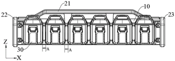
Fig. 1 is a schematic structural diagram of a multi-slot charger according to the present invention.
FIG. 2 is a front view of a housing of a multiple slot charger in an embodiment of the invention.
Fig. 3 is a schematic diagram illustrating the spacing between battery packs according to an embodiment of the invention.
FIG. 4 is a side view of a multiple slot charger in accordance with an embodiment of the present invention.
FIG. 5 is a rear view of a multiple slot charger according to an embodiment of the present invention.
Fig. 6 is a bottom view of a housing of a multiple slot charger in an embodiment of the invention.
Fig. 7 is a schematic axial view of a housing of a multiple-slot charger according to an embodiment of the invention.
Fig. 8 is a schematic structural diagram of the multiple slot charger with the first housing removed according to an embodiment of the invention.
Fig. 9 is a schematic diagram of a circuit board and socket assembly of a multi-slot charger according to an embodiment of the invention.
Fig. 10 is a schematic structural diagram of the multiple slot charger with the second housing removed according to an embodiment of the invention.
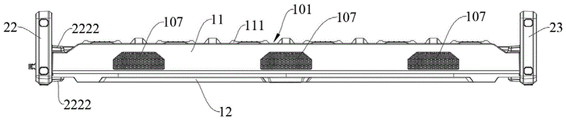
FIG. 11 is a top view of a housing of a multiple slot charger according to an embodiment of the invention.
Fig. 12 is a bottom view of a housing of a multiple slot charger according to an embodiment of the invention.
FIG. 13 is a diagram illustrating an assembly of a multi-slot charger and a battery pack according to an embodiment of the present invention.
FIG. 14 is a side view of a multiple slot charger in accordance with one embodiment of the present invention.
Fig. 15 is a schematic diagram of a socket assembly in a multiple-slot charger according to an embodiment of the invention.
Fig. 16 is a schematic view of the assembly of a metal insert and a charging interface in a multiple-slot charger according to an embodiment of the invention.
Fig. 17 is an exploded view of a metal insert and a charging interface in a multiple slot charger according to an embodiment of the invention.
Fig. 18 is a partial cross-sectional view taken along F-F in fig. 16.
FIG. 19 is a schematic diagram of an assembly of a battery pack and a charging interface in a multiple slot charger according to another embodiment of the invention.
FIG. 20 is a schematic diagram of a charging interface of a multiple-slot charger according to another embodiment of the invention.
FIG. 21 is a front view of a charging interface in a multiple slot charger in accordance with another embodiment of the present invention.
Fig. 22 is a schematic structural diagram of a battery pack according to an embodiment of the invention.
Fig. 23 is an exploded view of a battery pack according to an embodiment of the present invention.
FIG. 24 is a side view of an assembled multiple slot charger and battery pack of one embodiment of the present invention.
Fig. 25 is a schematic structural diagram of a battery pack according to another embodiment of the invention.
Fig. 26 is an exploded view of a battery pack according to another embodiment of the present invention.
Fig. 27 is a schematic view of a handle assembly in a multiple slot charger according to an embodiment of the invention.
FIG. 28 is a schematic view of an embodiment of the present invention showing the assembly of a handle and a multi-slot charger housing.
Fig. 29 is a schematic view of another angle assembly of the handle and the multi-slot charger housing in accordance with an embodiment of the present invention.
FIG. 30 is a schematic view of an embodiment of the present invention showing the assembly of a handle and a stiffener.
Fig. 31 is a schematic view illustrating a structure of a handle according to an embodiment of the present invention.
FIG. 32 is a schematic structural diagram of a stiffener according to an embodiment of the present invention.
FIG. 33 is an assembled view of an auxiliary handle according to an embodiment of the present invention.
FIG. 34 is a top view of a multiple slot charger and battery pack assembled in accordance with an embodiment of the present invention.
FIG. 35 is a schematic diagram illustrating a horizontal placement of a multiple-slot charger according to an embodiment of the invention.
Fig. 36 is a schematic view of an embodiment of a wall-mounted bracket and a multi-slot charger.
Fig. 37 is a schematic structural view of a wall-mounted fixing bracket according to an embodiment of the invention.
Description of reference numerals:
a multi-slot charger 100; a first housing 11; a fixed column 1101; a through hole 1102; a second housing 12; a handle assembly 20; a handle 21; a main body portion 211; a flat structure 212; a connecting column 213; a card slot 2131; a through hole 2132; a first auxiliary handle 22; a second auxiliary handle 23; a reinforcing plate 24; a threaded bore 242; mounting holes 243; a handle portion 221; a mounting portion 222; a ramp 2211; opening 2221; raised structures 2222; a recess 223; a first support leg 224; a second support leg 225; a charging tank 101; a circuit board assembly 102; a power supply interface 103; a changeover switch 1031; a first charging mode lamp 1041; a second charging mode lamp 1042; a charge slot indicator lamp 1043; a heat radiation fan 106; a first vent 107; a second vent 108; a ramp structure 109; a heat sink 110; a first charging interface 111; a groove 1111; a power supply terminal 112; metal insert 1113; a socket assembly 113; connecting plate 1131; a boss 1132; a second charging interface 114; a guide rail 1141; a groove structure 1142; a battery pack 30; an upper case 31; a handle 311; a lower case 32; a cell holder 33; a circuit board 34; a battery cell 35; a cell connecting sheet 36; a terminal interface 37; a mating interface 38; a battery pack 40; an upper case 41; a lower case 42; a cell holder 43; a circuit board 44; a terminal interface 47; a mating interface 48; a wall-mounted fixing bracket 115; a backplane surface 1151; a locating hole 11501; mounting holes 11502; a vent channel 11503; floor surface 1152; second bottom surface 11504.
Detailed Description
The embodiments of the present invention are described below with reference to specific embodiments, and other advantages and effects of the present invention will be readily apparent to those skilled in the art from the disclosure of the present specification. The invention is capable of other and different embodiments and of being practiced or of being carried out in various ways, and its several details are capable of modification in various respects, all without departing from the spirit and scope of the present invention.
It should be noted that the drawings provided in the present embodiment are only for illustrating the basic idea of the present invention, and the components related to the present invention are only shown in the drawings rather than drawn according to the number, shape and size of the components in actual implementation, and the type, quantity and proportion of the components in actual implementation may be changed randomly, and the layout of the components may be complicated.
The invention provides a multi-slot charger 100 which is used for solving the problems that the conventional charger can only charge one by one, the charging time greatly influences the working efficiency, and a large number of battery packs need large storage space for charging respectively, which brings great troubles to production and processing, and the heat dissipation effect of the conventional charger is poor. As shown in fig. 1 and fig. 36, the multiple-slot charger 100 includes a charger housing and a handle assembly 20, the handle assembly 20 is mounted on the charger housing 10, a plurality of charging slots 101 are disposed on the charger housing, the charging slots 101 are used for accommodating battery packs 30, a plurality of circuit board assemblies 102 are mounted in the charger housing, and a charging circuit is integrated on the circuit board assemblies 102 to charge the battery packs mounted on the charging slots 101.
As shown in fig. 1 to 6, in this embodiment, the charger housing includes a first housing 11 and a second housing 12, the first housing 11 and the second housing 12 are fixedly mounted together to form a receiving cavity, the circuit board assembly 102 is mounted in the receiving cavity, a power interface 103 is disposed on a side surface of the charger housing 10, the power interface 103 is electrically connected to the circuit board assemblies 102 in the receiving cavity, and the power interface 103 is further used for connecting an external power supply to provide a charging power supply for the multi-slot charger 100. In the present embodiment, a switch 1031 is further disposed on the side of the charger housing 10 where the power interface 103 is disposed, and the switch 1031 is located at the neutral position of the side of the charger housing 10. As shown in fig. 1, the direction along X in fig. 1 is the length direction of the housing of the multiple-slot charger, the direction along Y in fig. 1 is the width direction of the housing of the multiple-slot charger, and the direction along Z in fig. 1 is the height direction of the housing of the multiple-slot charger, and in the present embodiment, the ratio of the length, width and height of the housing of the multiple-slot charger is set to, for example, (5-11): (1-2): (2-3), in the present embodiment, the charger case is set to be 1068mm, 159mm, and 264mm in length, width, and height.
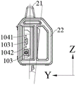
As shown in fig. 1 to fig. 6, in addition, in the present embodiment, the multi-slot charger 100 is provided with at least two charging modes, that is, a first charging mode and a second charging mode, the first charging mode is to start charging from the battery pack 30 with the lowest electric quantity, and the second charging mode is to start charging from the battery pack 30 with the highest electric quantity. The switch 1031 is used to control switching of the charging mode of the multi-slot charger 100, and in this embodiment, to control switching between a first charging mode and a second charging mode. In addition, in this embodiment, at least two charging indicator lamps are further disposed on one side of the charger housing 10, where the power interface 103 is disposed, and the charging indicator lamps are located on two sides of the switch 1031, so as to observe whether the multi-slot charger 100 is powered on and is in a working state, and when the charging indicator lamps are turned on, it indicates that the power is powered on and the multi-slot charger 100 is in the working state; if the charging indicator light goes off, it indicates that the power is not on and the multi-slot charger 100 is in a non-operating state.
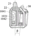
As shown in fig. 1 to 6, specifically, the charging indicator lights include a first charging mode light 1041 and a second charging mode light 1042, and when the first charging mode light 1041 is in a bright state and the second charging mode light 1042 is in an off state, it indicates that the multi-slot charger is in the first charging mode to operate, and the switch 1031 is pressed again, and when the second charging mode light 1042 is in a bright state and the first charging mode light 1041 is in an off state, it indicates that the multi-slot charger is in the second charging mode to operate.
As shown in fig. 1 to 6, in the present embodiment, a plurality of charging slots 101 are disposed on the charger housing 10, and the plurality of charging slots 101 are uniformly distributed on a side surface of the charger housing 10 to accommodate a plurality of battery packs 30, so as to charge the plurality of battery packs 30 at the same time. It should be noted that, in the present embodiment, a certain distance is provided between the charging slots 101, so as to avoid that when a plurality of battery packs 30 are simultaneously mounted on the multi-slot charger 100 to simultaneously charge the plurality of battery packs 30, two adjacent battery packs 30 interfere with each other, which is inconvenient or impossible to mount, and in the present embodiment, the distances a between every two charging slots 101 are equal.
As shown in fig. 1 and 3, in the present embodiment, a distance a is also maintained between the battery packs mounted on the charging slot 101, specifically, the distance a is a distance between adjacent sides of two adjacent battery packs, and the distance a is set to be, for example, between 3mm and 100mm, so as to serve as a safety distance of the battery packs during the charging process, avoid two adjacent battery packs from being too close to each other and from being scratched by collision during the inserting or extracting process, and otherwise, the operation is inconvenient if the two adjacent battery packs are too far apart. In this embodiment, the number of the charging slots 101 may be set to be 1, 2, 3, 4 or more, and in this embodiment, the number of the charging slots 101 is preferably 6, and the charging slots are symmetrically formed on the side of the first housing 11 away from the second housing 12, respectively, so as to charge the plurality of battery packs 30 at the same time.
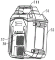
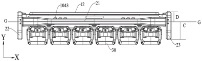
As shown in fig. 1 and 7, in the present embodiment, the multiple-slot charger 100 further includes a plurality of charging slot indicator lamps 1043, and the plurality of charging indicator lamps are disposed on the top of the first housing 11, and is located below the handle 21 in the handle assembly 20, and the number of the charging slot indicator lamps 1043 is one-to-one corresponding to the charging slots 101 on the multi-slot charger 100, in this embodiment, the number of the charging slot indicator lamps 1043 is preferably 6, and the charging slot indicator lamps 1043 are divided into two groups, the two groups of the charging slot indicator lamps 1043 are arranged symmetrically left and right with respect to the middle line O-O of the entire multi-slot charger 100 and are respectively located on the top of the second and fourth charging slots 101, when a battery pack 30 is inserted into a certain charging slot 101 and the battery pack is normally charged, the charging indicator lamp corresponding to the charging slot 101 is turned on. Of course, a plurality of the charging indicator lamps may be respectively located above the corresponding charging slot 101 or at other positions.
As shown in fig. 1, in the present embodiment, since the second housing 12 is long and thin, and is easily deformed or damaged, the inner wall of the second housing 12 may be provided with vertical and horizontal grid-shaped ribs to reinforce the second housing 12 and prevent the second housing 12 from being deformed or damaged.
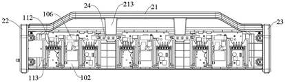
As shown in fig. 1, 8 and 9, in the present embodiment, a plurality of circuit board assemblies 102 are disposed in the charger housing 10, and a set of power supply terminals 112 is mounted on each charging slot 101, and the power supply terminals 112 and the charging circuits on the circuit board assemblies 102 form a charging loop to charge one battery pack 30. Specifically, each two charging slots 101 share one circuit board assembly 102, that is, each circuit board assembly 102 simultaneously forms two charging loops with the power supply terminals 112 on two charging slots 101, so as to simultaneously charge two battery packs 30, and the two charging loops do not interfere with each other. In addition, each circuit board assembly 102 is further provided with a heat dissipation fan 106, the charger housing 10 is provided with a second ventilation opening, and the second ventilation openings correspond to the heat dissipation fans 106 in a one-to-one manner, so as to achieve a heat dissipation effect on the circuit board assemblies 102, improve a heat dissipation effect of the multi-slot charger, and prolong a service life of the multi-slot charger.
As shown in fig. 1, 11 and 12, in the present embodiment, a plurality of first ventilation openings 107 and a plurality of second ventilation openings 108 are disposed on the charger housing 10, and the number of the first ventilation openings 107 and the number of the second ventilation openings 108 are respectively in one-to-one correspondence with the number of the circuit board assemblies 102, that is, in one-to-one correspondence with the number of the heat dissipation fans 106. Specifically, the first ventilation opening 107 is disposed at the bottom of the first housing 11, the second ventilation opening 108 is disposed at the top of the first housing 11, and the heat dissipation fan 106 is mounted on the circuit board assembly 102 and is opposite to the second ventilation opening 108 and is disposed near the top of the first housing 11, in some other embodiments, the number of the first ventilation openings 107 is greater than the number of the second ventilation openings 108.
As shown in fig. 1, 11 and 12, in addition, in the present embodiment, the first ventilation opening 107 and the second ventilation opening 108 are honeycomb-shaped, in other embodiments, other shapes may be provided, and the area ratio of the first ventilation opening 107 to the second ventilation opening 108 is set between 1 and 2, for example, under the area ratio, sufficient air flow can be ensured to pass through the high temperature component on the circuit board, so as to improve the ventilation effect, thereby enhancing the heat dissipation effect.
As shown in fig. 1, 4, 11 and 12, in particular, in this embodiment, the bottom surface of the charger housing 10 is inclined, that is, the bottom surface is a slope structure 109, in particular, the direction of the slope structure 109 is inclined downward from the first housing 11 to the second housing 12, an included angle α between the slope structure 109 and the ground is set between 3 ° and 6 °, and a distance L is set between the lowest point of the slope structure 109 and the ground, for example, the range of the distance L is set between 5mm and 20mm, in particular, in this embodiment, the included angle α between the slope structure 109 and the ground is preferably 3 °, and the distance L is preferably 16mm, so that the first vent 107 on the bottom surface of the charger housing 10 is always kept at a certain distance and angle from the bottom surface to prevent the first vent 107 from being blocked, the ventilation inside the multi-slot charger 100 is affected, so that the heat dissipation effect of the multi-slot charger 100 is affected, enough air enters the multi-slot charger 100, and the heat dissipation of high-temperature elements inside the multi-slot charger 100 is realized. And at this angle a, the first housing 11 of the multi-slot charger 100 is more easily demolded during the injection molding process.
As shown in fig. 8 and 9, in some embodiments, the multiple-slot charger 100 further includes a plurality of heat sink sets mounted on the circuit board assembly 102, specifically, in this embodiment, each of the heat sinks is disposed on the circuit board assembly 102 along a vertical direction, and a main air duct body is formed between the heat sinks 110 to enhance the heat dissipation effect thereof, and in some embodiments, the flow direction of the air flow is parallel to the heat sink 100 to further enhance the heat dissipation effect thereof.
As shown in fig. 1 and 14, in the present embodiment, the multi-slot charger 100 may adopt different placement manners, including a vertical type, a horizontal type and a hanging type, and different placement manners are adopted, so that no matter which placement manner (vertical type, horizontal type and wall hanging type) is adopted by the multi-slot charger 100, the battery pack 30 can be conveniently inserted into the first charging interface 111 of the multi-slot charger 100, so as to facilitate the operation thereof, and therefore, an included angle is set between the first charging interface 111 and the vertical line of the multi-slot charger 100, so as to facilitate the insertion or extraction between the battery pack 30 and the first charging interface 111 of the multi-slot charger 100.
As shown in fig. 1 and fig. 14, specifically, taking the vertical placement of the multi-slot charger 100 as an example for explanation, in this embodiment, the charging slot 101 is provided with a first charging interface 111, when the multi-slot charger 100 is placed in the vertical placement, the first charging interface 111 is obliquely arranged in the charging slot 101, the first charging interface 111 is arranged in the charging slot 101 from the top end of the multi-slot charger 100 to the bottom end of the multi-slot charger 100, that is, the top end of the first charging interface 111 is far away from the second housing 12, the bottom end of the first charging interface 111 is close to the second housing 12, specifically, in this embodiment, the vertical direction of the first charging interface 111 and the multi-slot charger 100 is provided with an included angle β, the included angle β is set between 0 ° and 60 °, and further, the included angle β is set between 0 ° and 45 °, and further, the included angle β is set between 0 ° and 30 °, and may also be set between 0 ° and 15 °, and further limited to 0 ° and 10 °, so that the battery pack 30 and the first charging interface 111 are installed in cooperation for charging.
As shown in fig. 1 and fig. 2, in the present embodiment, a charging rail is disposed on the first charging interface 111 to fit the battery pack 30, and a width B of the charging rail is set between 30mm and 90 mm. In addition, the total length L2 of the first charging interface 111 ranges from 100mm to 110mm to match with the matching interface on the battery pack 30, so that the battery pack can be firmly matched and charged.
As shown in fig. 1, 10 and 16, in addition, in the present embodiment, the inside of the first charging interface 111 is in a cavity state, and the top end thereof is recessed downward to form a groove 1111, the depth L1 of the groove 1111 ranges from 20mm to 30mm, and the bottom of the groove 1111 is installed with a power supply terminal 112, and the power supply terminal 112 is used for being connected with the terminal interface of the battery pack 30. Specifically, in this embodiment, a socket assembly 113 is disposed inside the multi-slot charger 100, the socket assembly 113 is fixedly connected to an inner wall of the first housing 11 and is in one-to-one correspondence with the charging slot 101, surfaces of two sides of the socket assembly 113 are flush with a bottom surface of the charging slot 101, the socket assembly 113 includes a connecting plate 1131, the connecting plate 1131 is located at a position near a top of the socket assembly 113, a boss 1132 is formed below the connecting plate 1131 and extends outward to support the power supply terminal 112, a plurality of through holes are disposed at intervals on the connecting plate 1131, and the power supply terminal 112 is connected to the socket assembly 113, so that a circuit inside the multi-slot charger 100 is connected to the power supply terminal 112.
As shown in fig. 13, 16 and 18, it should be further noted that in the present embodiment, a charging interface is included on the first charging interface 111 to facilitate the mating installation of the charging interface 111 and the battery pack, and a metal insert 1113 is embedded in the charging interface 111 to enhance the structural strength thereof, so as to prolong the service life thereof. Specifically, during the insertion of the battery pack 30 along the first charging interface 111, the first charging interface 111 may be subjected to a certain friction force, and during the use, the first charging interface 111 may also be subjected to a pressure applied thereto by the battery pack 30, so that the metal insert 1113 is embedded in the first charging interface 111 to enhance the structural strength of the first charging interface 111, and in other embodiments, the wall thickness of the first charging interface 111 may be increased or a reinforcing rib may be added to enhance the structural strength of the first charging interface 111.
As shown in fig. 14, 16, and 18, in the present embodiment, when a battery pack is mounted on the multiple slot charger 100, the ratio P between the total weight of the battery pack and the weight of the multiple slot charger 100 is set between 1/10 and 4. In the embodiment, the charging power range of the multi-slot charger is set between 200W and 2000W, for example, to meet the charging requirements under different conditions.
As shown in fig. 19 to 21, in another embodiment, the present invention further provides a second charging interface 114 instead of the first charging interface 111. Similarly, when the multi-slot charger 100 is placed vertically, the second charging interface 114 is obliquely arranged in the charging slot 101, the second charging interface 114 is arranged in the charging slot 101 from the top end of the multi-slot charger 100 to the bottom end of the multi-slot charger 100, that is, the top end of the second charging interface 114 is far away from the second housing 12, and the bottom end of the second charging interface 114 is close to the second housing 12, specifically, in the embodiment, the second charging interface 114 and the vertical direction of the multi-slot charger 100 are provided with an included angle β, the included angle β is set between 0 ° and 60 °, further, the included angle β is set between 0 ° and 45 °, further, the included angle β is set between 0 ° and 30 °, and also can be set between 0 ° and 15 °, further defined between 0 deg. and 10 deg., to facilitate the mating of the battery pack 30 and the second charging interface 114 for charging.
In another embodiment, as shown in fig. 19 to 21, the second charging interface 114 is a groove structure 1142, and the two opposite inner side walls of the groove structure 1142 are provided with guide rails 1141 to fit another battery pack 40. Also, in the present embodiment, the power supply terminal 112 is installed at the bottom of the second charging interface 114, and is used for connecting a terminal interface of the battery pack 40 to charge the battery pack 40.
As shown in fig. 1, 13, 22 and 23, in this embodiment, when the first charging interface 111 is disposed on the multi-slot charger 100, the battery pack 30 engaged therewith is a barrel-shaped battery pack, and correspondingly, the axis of the battery pack 30 and the vertical direction of the multi-slot charger 100 also have an included angle β, the included angle β is set between 0 ° and 60 °, further, the included angle β is set between 0 ° and 45 °, further, the included angle β is set between 0 ° and 30 °, further, the included angle β can be set between 0 ° and 15 °, and further, the included angle β is further defined between 0 ° and 10 °, so that the battery pack 30 and the second charging interface 114 can be engaged with each other to perform charging. In this embodiment, the battery pack 30 includes an upper casing 31, a lower casing 32, a cell support 33 and a circuit board 34, the upper casing 31 and the lower casing 32 are connected to form an accommodating cavity, the cell support 33 and the circuit board 34 are located in the accommodating cavity, a plurality of cells 35 are installed in the cell support 33, the cells 35 are electrically connected through cell connecting pieces 36, the circuit board 34 and the cells 35 are electrically connected, in addition, the battery pack 30 further includes a terminal interface 37, and the terminal interface 37 and the circuit board 34 are electrically connected.
As shown in fig. 1, 13, 19 and 23, in the present embodiment, a mating interface 38 that is mated with the first charging interface 111 is disposed on one side of the lower housing 32, the terminal interface 37 is located on the top of the mating interface 38, and the power supply terminal 112 is connected to the terminal interface 37 on the top of the mating interface 38 to charge the battery pack 30. In addition, in this embodiment, a handle 311 is further disposed on the upper casing 31 to facilitate the user to take or move the battery pack 30. It should be further noted that, when the battery pack 30 is installed on the multi-slot charger 100 for charging, the axial direction of the battery cell 35 in the battery pack 30 and the direction of the first charging interface 111 are parallel or perpendicular to each other, and in this embodiment, the directions are set to be perpendicular to each other.
As shown in fig. 1, 19, 25, and 26, in another embodiment, when a second charging interface 114 is disposed on the multi-slot charger 100, the battery pack 40 is a single-cell battery pack, the battery pack 40 includes an upper casing 41, a lower casing 42, a cell support 43, and a circuit board 44, the upper casing 41 and the lower casing 42 are connected to form a receiving cavity, the cell support 43 and the circuit board 44 are located in the receiving cavity, a plurality of cells (not shown) are mounted in the cell support 43, the plurality of cells are electrically connected by a cell connecting sheet (not shown), the circuit board 44 is electrically connected to the cells, the battery pack 40 further includes a terminal interface 47, and the terminal interface 47 is electrically connected to the circuit board 44.
As shown in fig. 1, 19, 25 and 26, in the present embodiment, a mating interface 48 is disposed on the upper housing 41 and is matched with the second charging interface 114, the terminal interface 47 is located at the mating interface 48, and when the battery pack 40 is installed in a mating manner with the second charging interface 114, the power supply terminal 112 is connected to the terminal interface 47 on the mating interface 48 to charge the battery pack 40. Similarly, when the battery pack 40 is installed on the multi-slot charger 100 for charging, the axial direction of the battery cells in the battery pack 40 is parallel to or perpendicular to the direction of the second charging interface 114.
As shown in fig. 1, 27 to 33, in this embodiment, the multiple slot charger 100 further includes a handle assembly, the handle assembly includes a handle 21, a first auxiliary handle 22 and a second auxiliary handle 23, specifically, the handle 21 is located on the top of the multiple slot charger 100 and is disposed on the top of the housing 10 along the length direction (X direction) of the housing 10, the first auxiliary handle 22 and the second auxiliary handle 23 are respectively installed on two sides of the multiple slot charger 100 along the length direction (X direction) and are fixedly connected to the first housing 11 and the second housing 12, and in some embodiments, two ends of the handle 21 are further fixedly connected to the first auxiliary handle 22 and the second auxiliary handle 23 respectively. Specifically, in this embodiment, the handle 21 is an arch-shaped structure, the middle main body portion 211 is similar to a cylinder, and two ends of the middle main body portion 211 are arranged to be flat structures 212, so as to be fixedly connected with the first auxiliary handle 22 and the second auxiliary handle 22, and in this embodiment, the main body portion 211 of the handle 21 extends downwards to form two connecting posts 213, and the connecting posts 213 extend into the inside of the multi-slot charger 100 through the through holes 1102 on the first housing 11, and are fixedly connected with the multi-slot charger 100 through the reinforcing plate 24.
As shown in fig. 1, 27 to 33, it should be noted that, in the present embodiment, since the multi-slot charger 100 is of an "elongated structure", the area where the first auxiliary handle 22 and the second auxiliary handle 22 are connected to the multi-slot charger 100 surrounds and fixes the end surfaces of the first housing 11 and the second housing 12 of the multi-slot charger 100, and then is connected to and fixed to the handle 21, so that the structure increases the force-bearing area, and is firmer and more firm as a whole. If the first auxiliary handle 22 and the second auxiliary handle 22 are removed, the handle 21 is directly fixed on the first casing 11 and/or the second casing 12 of the multi-slot charger 100 by screws, the stress is concentrated on the screw fixing point, the stress area is too small, and the casings are easy to damage.
As shown in fig. 1 and fig. 27 to fig. 33, in this embodiment, a clamping groove 2131 and a plurality of through holes 2132 are formed in a position of the connecting column 213 near the bottom, the plurality of through holes 2132 are located below the clamping groove 2131, the reinforcing plate 24 is also provided with a locking structure 241 matching with the clamping groove 2131 and a threaded hole 242 matching with the through hole 2132, that is, the reinforcing plate 24 is installed in a matching manner with the clamping groove 2131 through the locking structure 241, and then the connecting column 213 and the reinforcing plate 24 are fixedly connected together by passing a bolt through the through hole 2132 and the threaded hole 242, in addition, in this embodiment, both ends of the reinforcing plate 24 are further provided with mounting holes 243, the inner wall of the first housing 11 is provided with fixing columns 1101 matching with the mounting holes 243, that is, the fixing columns 1101 pass through the mounting holes 243, and are fastened by bolts to connect the reinforcing plate 24 with the multiple slot charger 100.
As shown in fig. 1, 27 to 33, in addition, in the present embodiment, the first auxiliary handle 22 and the second auxiliary handle 23 are symmetrically installed at two sides of the multiple slot charger 100, and are fixedly connected to the first casing 11, the second casing 12 and the handle 21, and the first auxiliary handle 22 and the second auxiliary handle 23 have the same structure.
As shown in fig. 1 and 27 to 33, in the present embodiment, the first auxiliary handle 22 is taken as an example for description, and the first auxiliary handle 22 includes a grip portion 221 and a mounting portion 222. Specifically, the mounting portion 222 includes an opening 2221, the opening 2221 can accommodate the first housing 11 and the second housing 12, that is, after the first housing 11 and the second housing 12 are fixedly mounted together, one end of the opening 2221 is located, and the mounting portion 222 is further provided with a plurality of protruding structures 2222, the protruding structures 2222 are respectively located at two sides of the opening 2221 and are symmetrically distributed, and the protruding structures 2222 are arranged along the height direction of the multi-slot charger 100, so as to be used for connecting the first housing 11 and the second housing 12 through bolts. In this embodiment, the number of the protruding structures 2222 is set to 4, for example, two sides of the opening 2221 are respectively set to 2, so as to be respectively and fixedly connected with the first casing 11 and the second casing 12 through bolts, and the top of the first auxiliary handle 22 is provided with a concave portion 223, the concave portion 223 is located above the opening 2221, and is used for being fixedly connected with the flat structures 212 at two ends of the handle 21, specifically, the flat structures 212 at two ends of the handle 21 are located in the concave portion 223 and are fixedly connected through bolts. In this embodiment, the handle portion 221 is fixedly connected to the mounting portion 222, or may be integrally formed, and is located at one side of the mounting portion 222, so as to facilitate a worker to take or move the multi-slot charger 100. In addition, in this embodiment, the top of the handle portion 221, which is far from the mounting portion 222, is provided with a slope 2211, and the angle between the slope 2211 and the vertical direction is set to 45 °, for example, so as to facilitate the operation of the operator.
As shown in fig. 1 and 34, since the side of the multiple-slot charger 100 where the battery pack is mounted is heavier and the center of gravity is easily deviated, the whole multiple-slot charger 100 is easily unbalanced and inclined to one side, and therefore, in the present embodiment, the handle assembly 20 is disposed at the top of the housing along the length direction (X direction), and the vertical distance between the two sides of the auxiliary handle and the center line G-G of the handle 21 in the handle assembly 20 in the width direction (Y direction) of the housing 10 is more than 1 to 3, specifically, the ratio of the vertical distance between the front side of the auxiliary handle and the center line of the handle 21 to the vertical distance between the rear side of the auxiliary handle and the center line of the handle 22 is more than 1 to 3, and the front side of the auxiliary handle is the side of the housing 10 where the charging slot is disposed, the rear side of the auxiliary handle is the side of the housing 10 where the second housing 12 is located. Specifically, the perpendicular distance between the center line of the handle 21 and the side of the auxiliary handle close to the charging slot 101 is C, the perpendicular distance between the axis of the handle 21 and the side of the auxiliary handle close to the second housing 12 is D, and the ratio between the perpendicular distance C and the perpendicular distance D ranges from 1 to 3, so as to ensure the stability of the whole multi-slot charger 100, thereby ensuring the stable charging process.
As shown in fig. 1, 24, 35 to 37, in the present embodiment, the multiple-slot charger 100 can be placed in a plurality of ways, including a vertical placement as shown in fig. 24, a horizontal placement as shown in fig. 35, and a wall-hung placement as shown in fig. 36, when the multiple-slot charger is placed in the vertical placement, the bottom surface of the auxiliary handle contacts the ground to support the multiple-slot charger, and at this time, the bottom edge 2201 of the auxiliary handle contacts the bottom surface to support the multiple-slot charger; when the multi-slot charger is placed in a horizontal position, the side 2202 of the assist grip contacts the bottom surface for support. In some embodiments, a first support leg 224 is provided on a side of the mounting portion 222 away from the handle portion 221, and a second support leg 225 is also provided on a bottom surface of the first auxiliary handle 22, wherein the two support legs are used for supporting the multi-slot charger 100 when the multi-slot charger 100 is placed in different positions, specifically, when the multi-slot charger 100 is placed in a vertical position, the second support leg 225 on the bottom surface of the first auxiliary handle 22 is used for supporting, and a worker can move the multi-slot charger 100 by using the handle 21; when the multiple slot charger 100 is placed in a lying position, the first support leg 224 on the side of the mounting portion 222 remote from the handle portion 221 functions as a support, and a worker can move the multiple slot charger 100 by using the handle portion 221. When a wall-mounted placement is used, the multiple slot charger 100 may be hung on a vertical wall by a wall-mounted fixture 115.
As shown in fig. 36 and 37, in the present embodiment, the wall-mounted fixing bracket 115 is fixedly mounted on the multi-slot charger 100, and the wall-mounted fixing bracket 115 surrounds the multi-slot charger 100 from four sides to wrap the multi-slot charger 100, specifically, the wall-mounted fixing bracket 115 includes a back plate surface 1151 for wrapping the second housing 12 of the multi-slot charger 100, and the back plate surface 1151 is respectively provided with positioning holes 11501 near upper positions of two sides, and two positioning holes 11501 are located on the same straight line, and the positioning holes 11501 are used for fixing and limiting the multi-slot charger 100, so as to ensure accurate positioning of the multi-slot charger 100 on the wall-mounted fixing bracket 115, so as to facilitate installation. In addition, since the back plate surface 1151 has a long length and a thin thickness, in order to ensure the strength of the back plate surface 1151, a plurality of ribs are formed on the back plate surface 1151 to increase the strength of the back plate surface 1151.
As shown in fig. 36 and 37, in this embodiment, the back plate surface 1151 further starts with a plurality of mounting holes 11502, the wall-hanging fixing bracket 115 is fixed on the vertical wall through the mounting holes 11502, and in this embodiment, the mounting holes 11502 are uniformly distributed on the back plate surface 1151, so as to ensure the uniformity of the stress applied to the wall-hanging fixing bracket 115 during the hanging process, and thus the stability of the hanging process.
As shown in fig. 36 and 37, in this embodiment, the wall-mounted fixing bracket 115 further includes a bottom plate 1152 for supporting and wrapping the bottom surface of the multi-slot charger 100, the bottom plate 1152 and the bottom surface of the multi-slot charger 100 are attached to each other to better support the multi-slot charger 100, and an included angle α ranging from 3 ° to 6 ° is provided between the bottom surface of the multi-slot charger 100 and a horizontal plane, so that an included angle ranging from 94 ° to 97 ° is correspondingly provided between the bottom plate 1152 and the back plate 1151 to better attach the bottom surface of the multi-slot charger 100.
As shown in fig. 36 and 37, in this embodiment, a plurality of ventilation grooves 11503 are further formed on the bottom plate 1152 at intervals, and the plurality of ventilation grooves 11503 respectively correspond to the first ventilation openings 107 at the bottom of the multi-groove charger 100 one by one, so that ventilation inside the multi-groove charger 100 is not affected, and the heat dissipation effect is not affected.
As shown in fig. 36 and 37, in this embodiment, the wall-mounted fixing bracket 115 further includes a first side plate and a second side plate for respectively wrapping the first auxiliary handle 22 and the second auxiliary handle 23 of the multi-slot charger 100, and the first side plate and the second side plate extend inward, i.e., in a direction of the base plate 1152, to form a second bottom surface 11504, and the second bottom surface 11504 is perpendicular to the back plate 1151, and the second bottom surface 11504 is used for supporting the first auxiliary handle 22 and the second auxiliary handle 23. In this embodiment, the bottom surface 1152 and the second bottom surface 11504 are both rigid stress surfaces, so as to better support the multi-slot charger 100, specifically, the weight of the battery pack 30 is transmitted to the multi-slot charger 100 through the first charging interface 111, and the weight of the multi-slot charger 100 is transmitted to the wall-hanging fixing bracket 115 through the first housing 11, the second housing 12, the first auxiliary handle 22 and the second auxiliary handle 23, and is fixed on a vertical wall through the mounting hole 11502 of the wall-hanging fixing bracket 115 by screws.
As shown in fig. 35 and 37, in this embodiment, the back plate surface 1151, the bottom plate surface 1152, the first side plate surface, the second side plate surface and the second bottom surface 11504 may be integrally formed therebetween, so as to further enhance the strength of the wall-hanging fixing bracket 115. In this embodiment, the wall-hanging fixing bracket 115 is, for example, a metal sheet, but aluminum or an alloy thereof may be used as long as the structural strength thereof can be satisfied. In this embodiment, the ratio of the weight of the wall-mounted bracket 115 to the weight of the multi-slot charger 100 with the battery pack mounted thereon ranges from 0.1 to 0.5, so that the battery pack is labor-saving during the moving or mounting process. It should also be noted that, for ease of movement and installation, the wall mounting bracket 115 is preferably lighter in weight, given its structural strength.
As shown in fig. 35 and 37, in the present embodiment, the installation process is that the wall-mounted fixing bracket 115 is fixed to a vertical wall by bolts through the mounting holes 11502 of the back plate surface 1151, the multi-slot charger 100 is placed on the wall-mounted fixing bracket 115, so that the bottom surface of the multi-slot charger 100 and the bottom plate surface 1152 of the wall-mount bracket 115 are attached to each other, and the first housing 11 and the back plate surface 1151 are attached to each other, and finally, the first housing is connected to the positioning hole 11501 of the back plate surface 1151 by passing through the multi-slot charger 100 by a bolt, so that the installation is completed after the multi-slot charger 100 is fixed on the wall-mounted fixing bracket 115, in another implementation of the present invention, the wall-mounted fixing bracket 115 may not be provided, that is, a plurality of slots or openings are directly formed on the first housing 11 for fastening with bolts fixed to a wall.
The invention provides a multi-slot charger, which is characterized in that a plurality of charging slots are arranged on the charger to charge a plurality of battery packs at the same time, so that the charging efficiency is improved, and meanwhile, the multi-slot charger is provided with two different charging modes, so that a user can rotate the different charging modes to charge the battery packs according to the requirements under different conditions. Simultaneously, be provided with certain interval between per two charging grooves to the installation battery package avoids two adjacent battery package mutual interference.
The invention provides a multi-slot charger, wherein a first ventilation opening and a second ventilation opening are respectively arranged at the bottom and the top of a shell, a heat dissipation fan is arranged in the shell, and meanwhile, the areas of the first ventilation opening and the second ventilation opening are set in a proper range, so that enough airflow can be ensured to pass through a high-temperature element on a circuit board, the ventilation effect of the multi-slot charger is improved, and the heat dissipation effect of the multi-slot charger is improved.
The invention provides a multi-slot charger, wherein an included angle beta is arranged between a charging interface and the multi-slot charger in the vertical direction, and the included angle beta is arranged within a reasonable range, so that a battery pack and the charging interface are very convenient to install in a matching manner within the range.
The invention provides a multi-slot charger, which is provided with a plurality of different placing modes, so that different placing modes can be adopted in different using scenes, and the multi-slot charger can be used more reasonably.
The invention provides a multi-groove charger, which is characterized in that a handle assembly is arranged to replace a mode that a handle is directly fixed on a first shell and/or a second shell of the multi-groove charger by screws, so that the situation that the stress is concentrated on a screw fixing point position is avoided, and the situation that the shells are easily damaged due to too small stress area is avoided.
The above description is only a preferred embodiment of the present application and the explanation of the technical principle used, and it should be understood by those skilled in the art that the scope of the present application is not limited to the technical solution of the specific combination of the above technical features, and also covers other technical solutions formed by any combination of the above technical features or their equivalent features without departing from the inventive concept, for example, the technical solutions formed by mutually replacing the above technical features (but not limited to) having similar functions disclosed in the present application.
Other technical features than those described in the specification are known to those skilled in the art, and are not described herein in detail in order to highlight the innovative features of the present invention.
Claims (13)
1. A heat dissipation structure for a multiple slot charger, comprising:
a plurality of first vents disposed at a bottom of a housing of the multiple slot charger;
a plurality of second vents provided at the top of the housing, and an area ratio of the first vents to the second vents is set between 1 and 2;
and the plurality of radiating fans are arranged in the shell and correspond to the plurality of second ventilation openings one by one.
2. The heat dissipation structure for a multiple slot charger of claim 1, wherein the first ventilation opening and the second ventilation opening are provided as honeycomb openings.
3. The heat dissipating structure for a multiple slot charger of claim 1, wherein the bottom surface of the multiple slot charger is a slope structure, and the angle between the slope structure and the ground is set between 3 ° and 6 °.
4. The heat dissipation structure for a multiple slot charger according to claim 1, comprising a plurality of fin groups vertically disposed on a circuit board assembly inside the housing and constituting a duct main body.
5. The heat dissipation structure for a multiple slot charger according to claim 4, wherein the heat dissipation fan is located at the air duct main body, and the heat dissipation fan is close to the second air opening.
6. The heat dissipation structure for a multiple slot charger of claim 4, wherein the first and second vents are both directly opposite the duct body.
7. A multiple slot charger, comprising:
a plurality of first vents disposed at a bottom of a housing of the multiple slot charger;
the plurality of second ventilation openings are arranged at the top of the shell;
the plurality of cooling fans are arranged in the shell and correspond to the plurality of second air vents one by one, and the area ratio of the first air vents to the second air vents is set between 1 and 2;
the charging grooves are formed in the shell, and a group of power supply terminals are arranged in each charging groove to be connected with a battery pack.
8. The multiple slot charger of claim 7 wherein the housing includes a first housing and a second housing, the first housing and the second housing being fixedly coupled to each other, the charging slot being located on the first housing.
9. The multiple-slot charger according to claim 7, wherein each charging slot is provided with a charging interface to match a mating interface on a battery pack, and a distance is provided between the battery packs on two adjacent charging interfaces, wherein the distance is in a range of 3mm to 100 mm.
10. The multiple-slot charger according to claim 7, wherein a switch is disposed on the multiple-slot charger, and the switch is used for controlling and switching the charging mode of the multiple-slot charger.
11. The multiple slot charger of claim 7, further comprising a plurality of charge indicator lights, wherein the plurality of charge indicator lights are disposed on a top portion of the housing.
12. The multiple slot charger of claim 11 wherein the number of charge indicator lights corresponds one-to-one to the number of charging slots on the multiple slot charger.
13. The multiple slot charger of claim 7, wherein two adjacent power supply terminals share a circuit board assembly.
Priority Applications (2)
| Application Number | Priority Date | Filing Date | Title |
|---|---|---|---|
| CN202111019995.2A CN114498805A (en) | 2021-09-01 | 2021-09-01 | Heat dissipation structure for multi-slot charger and multi-slot charger |
| PCT/CN2022/115694 WO2023030288A1 (en) | 2021-09-01 | 2022-08-30 | Multi-slot charger |
Applications Claiming Priority (1)
| Application Number | Priority Date | Filing Date | Title |
|---|---|---|---|
| CN202111019995.2A CN114498805A (en) | 2021-09-01 | 2021-09-01 | Heat dissipation structure for multi-slot charger and multi-slot charger |
Publications (1)
| Publication Number | Publication Date |
|---|---|
| CN114498805A true CN114498805A (en) | 2022-05-13 |
Family
ID=81491596
Family Applications (1)
| Application Number | Title | Priority Date | Filing Date |
|---|---|---|---|
| CN202111019995.2A Pending CN114498805A (en) | 2021-09-01 | 2021-09-01 | Heat dissipation structure for multi-slot charger and multi-slot charger |
Country Status (1)
| Country | Link |
|---|---|
| CN (1) | CN114498805A (en) |
Cited By (1)
| Publication number | Priority date | Publication date | Assignee | Title |
|---|---|---|---|---|
| WO2023030288A1 (en) * | 2021-09-01 | 2023-03-09 | 格力博(江苏)股份有限公司 | Multi-slot charger |
Citations (4)
| Publication number | Priority date | Publication date | Assignee | Title |
|---|---|---|---|---|
| US8450970B1 (en) * | 2007-05-14 | 2013-05-28 | Micro Power Electronics, Inc. | Small footprint portable battery charging station |
| CN108110819A (en) * | 2016-11-24 | 2018-06-01 | 创科(澳门离岸商业服务)有限公司 | Expansible portable power |
| CN211456714U (en) * | 2019-09-14 | 2020-09-08 | 浙江动一新能源动力科技股份有限公司 | Novel battery pack charging device with good heat dissipation effect |
| CN213547982U (en) * | 2020-10-28 | 2021-06-25 | 浙江明磊锂能源科技股份有限公司 | Heat dissipation shell of charging device |
-
2021
- 2021-09-01 CN CN202111019995.2A patent/CN114498805A/en active Pending
Patent Citations (4)
| Publication number | Priority date | Publication date | Assignee | Title |
|---|---|---|---|---|
| US8450970B1 (en) * | 2007-05-14 | 2013-05-28 | Micro Power Electronics, Inc. | Small footprint portable battery charging station |
| CN108110819A (en) * | 2016-11-24 | 2018-06-01 | 创科(澳门离岸商业服务)有限公司 | Expansible portable power |
| CN211456714U (en) * | 2019-09-14 | 2020-09-08 | 浙江动一新能源动力科技股份有限公司 | Novel battery pack charging device with good heat dissipation effect |
| CN213547982U (en) * | 2020-10-28 | 2021-06-25 | 浙江明磊锂能源科技股份有限公司 | Heat dissipation shell of charging device |
Cited By (1)
| Publication number | Priority date | Publication date | Assignee | Title |
|---|---|---|---|---|
| WO2023030288A1 (en) * | 2021-09-01 | 2023-03-09 | 格力博(江苏)股份有限公司 | Multi-slot charger |
Similar Documents
| Publication | Publication Date | Title |
|---|---|---|
| CN216312704U (en) | Multi-slot charger | |
| CN114498805A (en) | Heat dissipation structure for multi-slot charger and multi-slot charger | |
| CN111614145A (en) | Energy storage power supply | |
| CN113904398A (en) | Multi-slot charger | |
| CN113905552A (en) | Multi-slot charger | |
| CN113595212A (en) | Multi-slot charger | |
| CN113890130A (en) | Handle assembly for multi-slot charger and multi-slot charger | |
| CN215528666U (en) | Heat dissipation structure for multi-slot charger and multi-slot charger | |
| CN216055564U (en) | Multi-slot charger | |
| CN216413939U (en) | Multi-slot charger | |
| CN215772620U (en) | Handle assembly for multi-slot charger and multi-slot charger | |
| CN209282277U (en) | Electric tool high capacity cell pack arrangement | |
| WO2023030288A1 (en) | Multi-slot charger | |
| CN212627220U (en) | Energy storage power supply | |
| CN117937022A (en) | Energy storage power supply | |
| CN212322791U (en) | Install integrative current transformer of portable three-phase | |
| CN210806776U (en) | Battery pack charging seat structure | |
| CN219980479U (en) | Charging device | |
| CN111883703A (en) | Mobile energy storage device | |
| CN213782901U (en) | Charging device | |
| CN110544970A (en) | Battery pack charging seat structure | |
| CN219980475U (en) | Energy storage power supply device | |
| CN220895725U (en) | Shell and power supply | |
| CN210296427U (en) | Battery module shell and battery module | |
| CN215071719U (en) | Charging device |
Legal Events
| Date | Code | Title | Description |
|---|---|---|---|
| PB01 | Publication | ||
| PB01 | Publication | ||
| SE01 | Entry into force of request for substantive examination | ||
| SE01 | Entry into force of request for substantive examination |