CN114468635A - Beach sunshade chair capable of cooling by using light energy - Google Patents
Beach sunshade chair capable of cooling by using light energy Download PDFInfo
- Publication number
- CN114468635A CN114468635A CN202210070234.8A CN202210070234A CN114468635A CN 114468635 A CN114468635 A CN 114468635A CN 202210070234 A CN202210070234 A CN 202210070234A CN 114468635 A CN114468635 A CN 114468635A
- Authority
- CN
- China
- Prior art keywords
- plate
- sunshade
- sliding
- silica gel
- light energy
- Prior art date
- Legal status (The legal status is an assumption and is not a legal conclusion. Google has not performed a legal analysis and makes no representation as to the accuracy of the status listed.)
- Pending
Links
- 238000001816 cooling Methods 0.000 title claims abstract description 22
- VYPSYNLAJGMNEJ-UHFFFAOYSA-N Silicium dioxide Chemical compound O=[Si]=O VYPSYNLAJGMNEJ-UHFFFAOYSA-N 0.000 claims abstract description 30
- 239000000741 silica gel Substances 0.000 claims abstract description 30
- 229910002027 silica gel Inorganic materials 0.000 claims abstract description 30
- 230000007246 mechanism Effects 0.000 claims description 68
- 230000001681 protective effect Effects 0.000 claims description 18
- 239000004744 fabric Substances 0.000 claims description 10
- 238000009434 installation Methods 0.000 claims description 7
- 229910000838 Al alloy Inorganic materials 0.000 claims description 3
- 238000000151 deposition Methods 0.000 claims description 3
- 239000000463 material Substances 0.000 claims description 3
- 238000001179 sorption measurement Methods 0.000 claims description 2
- 230000000694 effects Effects 0.000 abstract description 6
- 230000008859 change Effects 0.000 abstract description 5
- 230000007613 environmental effect Effects 0.000 abstract description 2
- 229920001296 polysiloxane Polymers 0.000 description 16
- 239000003381 stabilizer Substances 0.000 description 8
- 230000009471 action Effects 0.000 description 6
- 230000008878 coupling Effects 0.000 description 3
- 238000010168 coupling process Methods 0.000 description 3
- 238000005859 coupling reaction Methods 0.000 description 3
- 230000007547 defect Effects 0.000 description 3
- 230000000295 complement effect Effects 0.000 description 2
- 229920002379 silicone rubber Polymers 0.000 description 2
- 230000009286 beneficial effect Effects 0.000 description 1
- 230000002146 bilateral effect Effects 0.000 description 1
- 238000013016 damping Methods 0.000 description 1
- 230000001815 facial effect Effects 0.000 description 1
- 230000005389 magnetism Effects 0.000 description 1
- 238000000034 method Methods 0.000 description 1
- 238000012986 modification Methods 0.000 description 1
- 230000004048 modification Effects 0.000 description 1
- 239000004945 silicone rubber Substances 0.000 description 1
- 238000006467 substitution reaction Methods 0.000 description 1
Images


Classifications
-
- A—HUMAN NECESSITIES
- A47—FURNITURE; DOMESTIC ARTICLES OR APPLIANCES; COFFEE MILLS; SPICE MILLS; SUCTION CLEANERS IN GENERAL
- A47C—CHAIRS; SOFAS; BEDS
- A47C1/00—Chairs adapted for special purposes
- A47C1/14—Beach chairs ; Chairs for outdoor use, e.g. chairs for relaxation or sun-tanning
- A47C1/143—Chaise lounges
-
- A—HUMAN NECESSITIES
- A47—FURNITURE; DOMESTIC ARTICLES OR APPLIANCES; COFFEE MILLS; SPICE MILLS; SUCTION CLEANERS IN GENERAL
- A47C—CHAIRS; SOFAS; BEDS
- A47C7/00—Parts, details, or accessories of chairs or stools
- A47C7/36—Support for the head or the back
- A47C7/40—Support for the head or the back for the back
- A47C7/46—Support for the head or the back for the back with special, e.g. adjustable, lumbar region support profile; "Ackerblom" profile chairs
- A47C7/462—Support for the head or the back for the back with special, e.g. adjustable, lumbar region support profile; "Ackerblom" profile chairs adjustable by mechanical means
-
- A—HUMAN NECESSITIES
- A47—FURNITURE; DOMESTIC ARTICLES OR APPLIANCES; COFFEE MILLS; SPICE MILLS; SUCTION CLEANERS IN GENERAL
- A47C—CHAIRS; SOFAS; BEDS
- A47C7/00—Parts, details, or accessories of chairs or stools
- A47C7/62—Accessories for chairs
Landscapes
- Health & Medical Sciences (AREA)
- Dentistry (AREA)
- General Health & Medical Sciences (AREA)
- Engineering & Computer Science (AREA)
- Mechanical Engineering (AREA)
- Special Chairs (AREA)
Abstract
The invention relates to a sunshade chair, in particular to a beach sunshade chair capable of cooling by utilizing light energy. The invention provides a beach sunshade chair which can adjust the angle of the beach chair, enables people to adapt comfortably and can change the sunshade area and utilize light energy to cool. The invention provides a beach sunshade chair capable of cooling by utilizing light energy, which comprises two support legs, a fixing frame, a silica gel pad, a first mounting plate and the like, wherein the two support legs are arranged in the front and back direction, the fixing frame and the first mounting plate are connected between the two support legs, and the first mounting plate is positioned on the right side of the fixing frame. Adjust silica gel pad right part inclination through the ratchet plate, can make the operating personnel lie on the silica gel pad more comfortably, the sunshading board can carry out lift adjustment to this area that can also change the sunshade when the sunshade, can turn into the electric energy with light energy through solar panel, supplies power to servo motor and fan, utilizes the light energy with this and reaches the effect of environmental protection.
Description
Technical Field
The invention relates to a sunshade chair, in particular to a beach sunshade chair capable of cooling by utilizing light energy.
Background
In summer, most people like to lie on a beach for sunbathing or have a rest for a short time, but because the long-time irradiation of sunlight can cause harm to human bodies, people can often see the combination of a beach chair and a sunshade umbrella on the beach, and because the weather is hot, the light is that the beach chair and the sunshade umbrella can not be well cooled, and the beach chair is not convenient to carry, so that the beach chair which can be cooled and can also shade the sun is designed, and the beach chair has a good commercial prospect.
Grant a sunshade chair convenient to ventilative for CN209474123U according to the patent, the on-line screen storage device comprises a base, the both ends fixedly connected with connecting rod of base, the inside fixedly connected with damping spring of lower extreme of base, the equal fixedly connected with gyro wheel in lower extreme both sides of bottom plate, orbital inside swing joint has U type frame, the upper end right side fixedly connected with stabilizer blade of U type frame, the upper end fixedly connected with handle of stabilizer blade, the first board of placing of upper end left side fixedly connected with of U type frame, the first board of placing is placed to the left side fixedly connected with second of board, the first upper end fixedly connected with cushion of placing the board.
Above-mentioned sunshade chair convenient to ventilative ventilate sits the cushion and leans on the back through setting up articulated elements and sunshading board, utilizes the sunshading board to keep off in facial top, can reach the effect of sunshade, and this kind of method has reached the effect of sunshade, but can't carry out the regulation of sandy beach chair's angle, can not make people adapt to comfortably to can't change the area of sunshade.
According to the defects in the prior art, the beach sunshade chair capable of adjusting the angle of the beach chair, enabling people to adapt comfortably and changing the sunshade area and utilizing the light energy to cool is designed.
Disclosure of Invention
In order to overcome the defects that the angle of the beach chair cannot be adjusted, people cannot comfortably adapt to the beach chair, and the sun-shading area cannot be changed in the prior art, the invention provides the beach sun-shading chair which can adjust the angle of the beach chair, comfortably adapt to the people, and change the sun-shading area and can reduce the temperature by using light energy.
In order to solve the technical problem, the invention provides a beach sunshade chair capable of cooling by utilizing light energy, which comprises two support legs, a fixing frame, a silica gel pad, a first mounting plate, an adjusting mechanism, a sunshade mechanism and a cooling mechanism, wherein the two support legs are arranged in a front-back manner, the fixing frame and the first mounting plate are connected between the two support legs, the first mounting plate is positioned on the right side of the fixing frame, the silica gel pad is connected onto the fixing frame, the adjusting mechanism is arranged on the silica gel pad and the first mounting plate, the sunshade mechanism is arranged on the first mounting plate, and the cooling mechanism is arranged on the sunshade mechanism.
Preferably, adjustment mechanism is including fan-shaped guide rail, second reset spring, first guide arm, the ratchet plate, the fixture block, third reset spring, guide block and U type frame, be connected with fan-shaped guide rail between first mounting panel and the silica gel pad, the gliding style is equipped with ratchet plate and first guide arm on the fan-shaped guide rail, be connected with second reset spring between first guide arm and the silica gel pad, second reset spring is located inside fan-shaped guide rail, first guide arm links to each other with the ratchet plate, the ratchet plate links to each other with the silica gel pad, the symmetry formula is equipped with the guide block around first mounting panel left part downside, the U type frame has been run through to the slidingtype between two guide blocks, U type frame right side is connected with the fixture block, fixture block and ratchet plate contact, be connected with third reset spring between fixture block and the guide block, third reset spring is around establishing in the U type frame outside.
Preferably, the sunshade mechanism is including the installation pole, the sliding block, the sunshading board, the connecting plate, the stay cord, first reset spring, the pipe, fixed plate and connecting rod, all open the spout on two ratchet plate one side in opposite directions, slidingtype is equipped with the connecting rod between two spouts, first mounting panel lower part right side longitudinal symmetry formula is equipped with the installation pole, the cover is equipped with the fixed plate between two installation pole middle parts, fixed plate middle part right side is connected with the pipe, installation pole upper portion slidingtype cover is equipped with the sliding block, be connected with first reset spring between sliding block and the fixed plate, first reset spring is around establishing in the installation pole outside, be connected with connecting plate and sunshading board between two sliding blocks, the sunshading board is located silica gel pad directly over and connecting plate left, the connecting plate downside is connected with the stay cord, stay cord tail end slidingtype runs through in the pipe and links to each other with the connecting rod.
Preferably, cooling mechanism is including solar panel, articulated piece, servo motor, the protecting crust, fan and battery, solar panel and servo motor are installed respectively to both sides about the sunshading board right part, the battery is installed to solar panel right part upside, sunshading board right part below is connected with two articulated pieces, two articulated pieces all are located servo motor the place ahead, servo motor output shaft rotary type runs through between two articulated pieces, the cover is equipped with the protecting crust on the servo motor output shaft, the fan is all installed to both sides around the protecting crust, the air supply outlet has been opened to the protecting crust downside, solar panel and battery pass through electric connection, servo motor and fan all pass through electric connection with the battery.
Preferably, still including ejecting mechanism, ejecting mechanism is including the strut, the sliding plate, the deflector, cover cloth, second guide arm and coupling spring, both sides all are connected with the deflector around the sunshading board downside, fixed plate middle part upside is connected with the strut, all be connected with the second guide arm on two sliding blocks one side in opposite directions, equal slidingtype cover is equipped with the sliding plate on two second guide arms, the sliding plate downstream can contact with the strut, be connected with coupling spring between sliding plate and the sliding block, coupling spring is around establishing in the second guide arm outside, all be connected with on two sliding plate one side that leaves and cover cloth, cover cloth slidingtype and establish on the deflector.
Preferably, still including complementary unit, complementary unit is equipped with the second mounting panel including second mounting panel, first push pedal, L type pole and ejector pad, bilateral symmetry formula around the mount, and the gliding formula of going through has L type pole on the second mounting panel, and L type pole removes left and can contact with U type frame, and L type pole upside is connected with the ejector pad, and the gliding formula of going through has first push pedal on the second mounting panel, first push pedal and ejector pad contact.
Preferably, still including depositing the mechanism, deposit the mechanism including putting the board, the protective housing, deposit the case, magnetic path and second push pedal, all be connected with on the one side that two second installation boards are from each other and put the board, it is connected with the protective housing to put the board downside, the inside slidingtype of protective housing is equipped with deposits the case, it is equipped with the magnetic path all to slidingtype on the opposite one side of two protective housings, magnetic path magnetic adsorption lives deposits the case, first push pedal downside is connected with the second push pedal, the second push pedal can contact with the magnetic path.
Preferably, the material of stabilizer blade is the aluminum alloy.
On the basis of overcoming the defects of the prior art, the invention can also achieve the following beneficial effects:
1. adjust silica gel pad right part inclination through the ratchet plate, can make the operating personnel lie on the silica gel pad more comfortably, the sunshading board can carry out lift adjustment to this area that can also change the sunshade when the sunshade, can turn into the electric energy with light energy through solar panel, supplies power to servo motor and fan, utilizes the light energy with this and reaches the effect of environmental protection.
2. When the sun shield moves downwards to increase the sun-shading area of the silica gel pad, the covering cloths on the front side and the rear side automatically move in the direction away from each other and respectively shade the front upper part and the rear upper part of the silica gel pad, so that the sun-shading area is further increased.
3. When an operator lies on the silica gel pad, the ratchet plate can be loosened through moving the first push plate leftwards, so that the inclination angle of the silica gel pad can be adjusted conveniently.
4. The storage box and the placing plate which are moved out facilitate the placement of various articles, so that the using effect of an operator can be improved.
Drawings
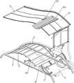
Fig. 1 is a schematic perspective view of a first embodiment of the present invention.
Fig. 2 is a schematic perspective view of a second embodiment of the present invention.
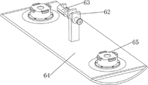
Fig. 3 is a schematic perspective view of a portion of the cooling mechanism of the present invention.
Fig. 4 is a partial perspective sectional view of the cooling mechanism of the present invention.
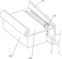
Fig. 5 is a schematic perspective view of the sunshade mechanism of the present invention.
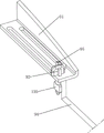
Fig. 6 is a schematic view of a first partially assembled structure of the sunshade mechanism and the push-out mechanism of the present invention.
Fig. 7 is a schematic view of a second partially assembled structure of the sunshade mechanism and the push-out mechanism of the present invention.
FIG. 8 is a schematic perspective view of a portion of the sunshade mechanism of the present invention.
Fig. 9 is an enlarged view of the invention at a.
Fig. 10 is a partial perspective view of the present invention.
Fig. 11 is a partial perspective sectional view of the adjustment mechanism and storage mechanism of the present invention.
Fig. 12 is a schematic view of a first partially separated body structure of the assisting mechanism and the storing mechanism of the present invention.
Fig. 13 is a partial perspective view of the auxiliary mechanism of the present invention.
Fig. 14 is a schematic view of a second partially separated body structure of the assisting mechanism and the storing mechanism of the present invention.
The labels in the figures are: 1-foot, 2-fixed frame, 3-silicon rubber cushion, 4-first mounting plate, 5-sun shading mechanism, 51-mounting rod, 52-sliding block, 53-sun shading plate, 54-connecting plate, 55-pulling rope, 56-first return spring, 58-guide pipe, 59-fixing plate, 510-connecting rod, 6-cooling mechanism, 61-solar panel, 62-hinged block, 63-servo motor, 64-protective shell, 65-fan, 66-storage battery, 7-adjusting mechanism, 71-fan-shaped guide rail, 72-second return spring, 73-first guide rod, 74-toothed plate ratchet, 75-clamping block, 76-third return spring, 77-guide block, 78-U-shaped frame, 8-pushing-out mechanism, 81-support frame, 82-sliding plate, 83-guide plate, 84-covering cloth, 85-second guide rod, 86-connecting spring, 9-auxiliary mechanism, 91-second mounting plate, 92-first push plate, 94-L-shaped rod, 95-push block, 10-storage mechanism, 101-placing plate, 102-protective box, 103-storage box, 104-magnetic block and 105-second push plate.
Detailed Description
The invention is further described below with reference to the figures and examples.
Example 1
The utility model provides a sandy beach sunshade chair that utilizes light energy cooling, as shown in figure 1, fig. 2, fig. 3, fig. 4, fig. 5, fig. 8, fig. 9, fig. 10 and fig. 11, including stabilizer blade 1, mount 2, silica gel pad 3, first mounting panel 4, adjustment mechanism 7, sunshade mechanism 5 and cooling mechanism 6, stabilizer blade 1 is equipped with two, the material of stabilizer blade 1 is the aluminum alloy, the quality is lighter, intensity is harder, two stabilizer blades 1 are the setting from beginning to end, mount 2 and first mounting panel 4 have been bolted between two stabilizer blades 1, first mounting panel 4 is located the mount 2 right-hand, bolted on mount 2 has silica gel pad 3, be provided with adjustment mechanism 7 on silica gel pad 3 and the first mounting panel 4, be provided with sunshade mechanism 5 on the first mounting panel 4, be provided with cooling mechanism 6 on the sunshade mechanism 5.
As shown in fig. 10-11, the adjusting mechanism 7 includes a fan-shaped guide rail 71, a second return spring 72, a first guide rod 73, a ratchet plate 74, a latch block 75, a third return spring 76, a guide block 77 and a U-shaped frame 78, the fan-shaped guide rail 71 is bolted between the first mounting plate 4 and the silicone pad 3, the ratchet plate 74 and the first guide rod 73 are slidably disposed on the fan-shaped guide rail 71, the second return spring 72 is connected between the first guide rod 73 and the silicone pad 3, the second return spring 72 is located inside the fan-shaped guide rail 71, the first guide rod 73 is connected with the ratchet plate 74, the ratchet plate 74 is connected with the silicone pad 3, the guide blocks 77 are symmetrically disposed at the front and back of the left lower side of the first mounting plate 4, the U-shaped frame 78 is slidably penetrated between the two guide blocks 77, the latch block 75 is bolted at the right side of the U-shaped frame 78, the latch block 75 is contacted with the ratchet plate 74, the third return spring 76 is connected between the latch block 75 and the guide block 77, the third return spring 76 is wound around the outside of the U-shaped frame 78.
As shown in fig. 5-6, the sunshade mechanism 5 includes a mounting rod 51, a sliding block 52, a sunshade plate 53, a connecting plate 54, a pulling rope 55, a first return spring 56, a guide tube 58, a fixing plate 59 and a connecting rod 510, wherein the opposite sides of the two ratchet plates 74 are respectively provided with a sliding groove, the connecting rod 510 is slidably arranged between the two sliding grooves, the mounting rod 51 is symmetrically arranged on the right side of the lower portion of the first mounting plate 4 in a front-back manner, the fixing plate 59 is sleeved between the middle portions of the two mounting rods 51, the guide tube 58 is welded on the right side of the middle portion of the fixing plate 59, the sliding block 52 is slidably sleeved on the upper portion of the mounting rod 51, the first return spring 56 is connected between the sliding block 52 and the fixing plate 59, the first return spring 56 is wound on the outer side of the mounting rod 51, the connecting plate 54 and the sunshade plate 53 are bolted between the two sliding blocks 52, the sunshade plate 53 is located right above the silicone pad 3, the sunshade plate 53 is located on the left of the connecting plate 54, a pull rope 55 is connected to the lower side of the connecting plate 54, and the tail end of the pull rope 55 slidably penetrates through the conduit 58 and is connected with the connecting rod 510.
As shown in fig. 2-5, the cooling mechanism 6 includes a solar panel 61, hinged blocks 62, a servo motor 63, a protective shell 64, a fan 65 and a storage battery 66, the upper and lower sides of the right portion of the sun shield 53 are respectively provided with the solar panel 61 and the servo motor 63 through screws, the storage battery 66 is arranged on the upper side of the right portion of the solar panel 61 through screws, the lower side of the right portion of the sun shield 53 is welded with two hinged blocks 62, the two hinged blocks 62 are all located in front of the servo motor 63, the output shaft of the servo motor 63 rotatably runs through the two hinged blocks 62, the protective shell 64 is sleeved on the output shaft of the servo motor 63, the fan 65 is arranged on the front and rear sides of the protective shell 64 through bolts, the lower side of the protective shell 64 is provided with an air supply opening, the solar panel 61 and the storage battery 66 are electrically connected, and the servo motor 63 and the fan 65 are both electrically connected with the storage battery 66.
Firstly, when using the device, an operator drives the latch 75 to move leftward through the U-shaped frame 78, the third return spring 76 compresses, the latch 75 moves leftward to release the ratchet plate 74, the operator drives the ratchet plate 74 to rotate clockwise along the fan-shaped guide rail 71, the ratchet plate 74 drives the right portion of the silicone pad 3 to move downward, the ratchet plate 74 also drives the first guide rod 73 to rotate clockwise along the fan-shaped guide rail 71, the second return spring 72 compresses, the operator releases the U-shaped frame 78, the third return spring 76 resets, the latch 75 moves rightward under the reset action of the third return spring 76 to re-clamp the ratchet plate 74, so as to adjust the right tilt angle of the silicone pad 3, during the clockwise rotation of the ratchet plate 74 along the fan-shaped guide rail 71, the upper side wall of the sliding slot on the ratchet plate 74 contacts the connecting rod 510, the connecting rod 510 is forced to pull the connecting plate 54 downward through the pull rope 55, the connecting plate 54 drives the sun visor 53 to move downwards through the sliding block 52, the first return spring 56 is compressed, so that the sun visor 53 can be close to the silicone pad 3 while the inclination angle of the silicone pad 3 is adjusted, and further the area for shading the silicone pad 3 is increased, initially, the solar panel 61 can convert absorbed light energy into electric energy, and then the electric energy is transmitted into the storage battery 66, the operator can reuse the electric starting fan 65 in the storage battery 66, the fan blades on the fan 65 can rotate to blow air to the silicone pad 3 through the air supply opening on the protective shell 64, so that the effect of cooling the silicone pad 3 can be achieved, the operator can reuse the electric starting servo motor 63 in the storage battery 66, so that the output shaft of the servo motor 63 drives the protective shell 64 to rotate clockwise, the protective shell 64 then drives the fan 65 to rotate clockwise by taking the output shaft of the servo motor 63 as the center of a circle, so as to complete the adjustment of the angle of the fan 65, then the servo motor 63 is turned off, after the cooling operation is completed, the operator turns off the blower 65, the fixture block 75 is moved leftwards again through the U-shaped frame 78, the third return spring 76 is compressed, the fixture block 75 releases the ratchet plate 74, the second return spring 72 is reset, the first guide rod 73 drives the ratchet plate 74 to rotate anticlockwise along the fan-shaped guide rail 71 under the reset action of the second return spring 72, the ratchet plate 74 drives the right portion of the silica gel pad 3 to move upwards, therefore, the silicone rubber pad 3 can be reset, meanwhile, the upper side wall of the sliding groove on the ratchet plate 74 can release the connecting rod 510 and enable the lower side wall to be in contact with the connecting rod, the pulling rope 55 is loosened, the first return spring 56 is reset, the sliding block 52 enables the sun visor 53 to move upwards to reset under the reset action of the first return spring 56, the operator releases the U-shaped frame 78, the third return spring 76 is reset, and the clamping block 75 clamps the ratchet plate 74 again under the reset action of the third return spring 76.
Example 2
On the basis of embodiment 1, as shown in fig. 1, 6 and 7, the sun visor includes a push-out mechanism 8, the push-out mechanism 8 includes a support 81, a sliding plate 82, a guide plate 83, a covering cloth 84, a second guide rod 85 and a connecting spring 86, the guide plates 83 are welded on the front and rear sides of the lower side of the sun visor 53, the support 81 is connected to the upper side of the middle of the fixed plate 59, the second guide rod 85 is bolted to the opposite side of the two sliding blocks 52, the sliding plate 82 is slidably sleeved on the two second guide rods 85, the sliding plate 82 can contact with the support 81 when moving downward, the connecting spring 86 is connected between the sliding plate 82 and the sliding blocks 52, the connecting spring 86 is wound outside the second guide rod 85, the covering cloth 84 is connected to the opposite side of the two sliding plates 82, and the covering cloth 84 is slidably arranged on the guide plate 83.
When the pulling rope 55 pulls the connecting plate 54 downwards to drive the sun visor 53 to move downwards so as to increase the sun-shading area of the silicone pad 3, the sliding block 52 drives the two sliding plates 82 to move downwards, the two sliding plates 82 move downwards to be contacted with the support frame 81 and move in the direction of being away from each other under stress, the connecting spring 86 is compressed, the two sliding plates 82 move away from each other and also drive the two covering cloths 84 to move in the direction of being away from each other, the covering cloths 84 can gradually separate from the support of the guide plate 83 at the moment, the separated ends of the two covering cloths 84 can incline downwards due to losing the support, the covering cloths 84 shade the front upper part and the rear upper part of the silicone pad 3, so that the sun-shading area can be increased through the covering cloths 84, and then when the two sliding plates 82 are driven to move upwards to reset by the sliding block 52, the two sliding plates 82 can gradually separate from the support frame 81, and the connecting spring 86 resets, the two sliding plates 82 are reset by the reset action of the connecting spring 86 and drive the two cover cloths 84 to approach each other, so that the cover cloths 84 can be folded.
Example 3
On the basis of the embodiment 2, as shown in fig. 1, 11, 12 and 13, the device further includes an auxiliary mechanism 9, the auxiliary mechanism 9 includes a second mounting plate 91, a first push plate 92, an L-shaped rod 94 and a push block 95, the second mounting plate 91 is symmetrically disposed on the front and rear sides of the fixing frame 2, the L-shaped rod 94 slidably penetrates through the second mounting plate 91, the L-shaped rod 94 moves leftwards and can contact with the U-shaped frame 78, the push block 95 is bolted to the upper side of the L-shaped rod 94, the first push plate 92 slidably penetrates through the second mounting plate 91, and the first push plate 92 contacts with the push block 95.
Initially, when an operator lies on the silicone pad 3, and needs to adjust the inclination angle of the right portion of the silicone pad 3, the operator can drive the first push plates 92 on the front and rear sides of the fixing frame 2 to move leftward, the first push plates 92 move leftward to push the L-shaped rods 94 to move leftward, the L-shaped rods 94 move leftward to drive the latch 75 to move leftward through the U-shaped frame 78, the third return spring 76 compresses to release the latch plate 74 from the latch 75, so as to adjust the inclination angle of the silicone pad 3, the operator releases the first push plates 92 again, the third return spring 76 returns to the original position, the latch 75 locks the latch plate 74 again under the action of the return of the third return spring 76 and drives the U-shaped frame 78 to move rightward, and the U-shaped frame 78 moves rightward to drive the first push plates 92 to move rightward through the L-shaped rods 94 to return to the original position.
Example 4
On the basis of embodiment 3, as shown in fig. 1, 12 and 14, the storage device further includes a storage mechanism 10, the storage mechanism 10 includes a placement plate 101, a protection box 102, a storage box 103, magnetic blocks 104 and second push plates 105, the placement plate 101 is bolted to the separated side of the two second mounting plates 91, the protection box 102 is connected to the lower side of the placement plate 101, the storage box 103 is slidably arranged inside the protection box 102, the magnetic blocks 104 are slidably arranged on the opposite sides of the two protection boxes 102, the storage box 103 is magnetically attracted by the magnetic blocks 104, the second push plates 105 are connected to the lower side of the first push plate 92, and the second push plates 105 can contact with the magnetic blocks 104.
Firstly, the second push plate 105 can not contact the magnetic block 104 when moving, an operator drives the second push plate 105 to rotate 90 degrees through the first push plate 92, the first push plate 92 can not contact the L-shaped rod 94 at the moment, the second push plate 105 can contact the right side of the magnetic block 104 when rotating 90 degrees, the operator moves the second push plate 105 leftwards through the first push plate 92, the second push plate 105 can drive the magnetic block 104 to move leftwards, the magnetic block 104 drives the storage box 103 to move leftwards through magnetism, so that the storage box 103 can be moved out, the operator can use the moved storage box 103 and the placement plate 101 for placing articles, then the operator drives the second push plate 105 to rotate 90 degrees through the first push plate 92 to separate from the magnetic block 104, moves the second push plate 105 leftwards, rotates the second push plate 105 again to drive the second push plate 105 to rotate 90 degrees through the first push plate 92, the second push plate 105 at the moment can contact the left side of the magnetic block 104 when rotating 90 degrees, the operator moves the second push plate 105 rightwards through the first push plate 92, and the second push plate 105 drives the storage box 103 to move rightwards through the magnetic block 104, so that the storage box 103 can be reset rightwards.
The above examples are merely representative of preferred embodiments of the present invention, and the description thereof is more specific and detailed, but not to be construed as limiting the scope of the present invention. It should be noted that, for those skilled in the art, various changes, modifications and substitutions can be made without departing from the spirit of the present invention, and these are all within the scope of the present invention. Therefore, the protection scope of the present patent shall be subject to the appended claims.
Claims (8)
1. A beach sunshade chair using light energy to cool comprises two support legs (1), a fixing frame (2), a silica gel pad (3) and a first mounting plate (4), wherein the two support legs (1) are arranged in the front and back direction, the fixing frame (2) and the first mounting plate (4) are connected between the two support legs (1), the first mounting plate (4) is positioned at the right side of the fixing frame (2), the silica gel pad (3) used for lying down is connected on the fixing frame (2), the silica gel pad is characterized by further comprising an adjusting mechanism (7), a sun-shading mechanism (5) and a cooling mechanism (6), wherein the adjusting mechanism (7) used for adjusting the right inclination angle of the silica gel pad (3) is arranged on the silica gel pad (3) and the first mounting plate (4), the sun-shading mechanism (5) used for shading sun is arranged on the first mounting plate (4), and the cooling mechanism (6) used for cooling is arranged on the sun-shading mechanism (5).
2. The beach sun-shading chair capable of reducing the temperature by using the light energy as claimed in claim 1, wherein the adjusting mechanism (7) comprises a fan-shaped guide rail (71), a second return spring (72), a first guide rod (73), a ratchet plate (74), a clamping block (75), a third return spring (76), a guide block (77) and a U-shaped frame (78), the fan-shaped guide rail (71) is connected between the first mounting plate (4) and the silica gel pad (3), the fan-shaped guide rail (71) is slidably provided with the ratchet plate (74) and the first guide rod (73) for pulling the silica gel pad (3), the second return spring (72) is connected between the first guide rod (73) and the silica gel pad (3), the second return spring (72) is positioned inside the fan-shaped guide rail (71), the first guide rod (73) is connected with the ratchet plate (74), the ratchet plate (74) is connected with the silica gel pad (3), the guide block (77) is symmetrically arranged at the front and back of the lower side of the left part of the first mounting plate (4), u-shaped frame (78) is penetrated between two guide blocks (77) in a sliding mode, a clamping block (75) is connected to the right side of the U-shaped frame (78), the clamping block (75) is in contact with the ratchet plate (74), a third return spring (76) is connected between the clamping block (75) and the guide blocks (77), and the third return spring (76) is wound on the outer side of the U-shaped frame (78).
3. The beach sunshade chair using light energy to cool according to claim 2, characterized in that the sunshade mechanism (5) comprises mounting rods (51), sliding blocks (52), a sunshade plate (53), a connecting plate (54), a pull rope (55), a first return spring (56), a guide tube (58), a fixing plate (59) and a connecting rod (510), sliding grooves are respectively arranged on the opposite sides of the two ratchet plates (74), the connecting rod (510) is slidably arranged between the two sliding grooves, the mounting rods (51) are symmetrically arranged on the front and back of the right side of the lower part of the first mounting plate (4), the fixing plate (59) is sleeved between the middle parts of the two mounting rods (51), the guide tube (58) is connected to the right side of the middle part of the fixing plate (59), the sliding block (52) is sleeved on the upper part of the mounting rod (51), and the first return spring (56) is connected between the sliding block (52) and the fixing plate (59), first reset spring (56) is around establishing in installation pole (51) outside, is connected with connecting plate (54) and sunshading board (53) that are used for the sunshade between two sliding blocks (52), and sunshading board (53) are located silica gel pad (3) directly over and connecting plate (54) left, and connecting plate (54) downside is connected with stay cord (55) that are used for transmitting power, and stay cord (55) tail end slidingtype runs through in pipe (58) and links to each other with connecting rod (510).
4. The beach sun-shading chair capable of reducing the temperature by using the light energy as claimed in claim 3, wherein the temperature reducing mechanism (6) comprises a solar panel (61), a hinge block (62), a servo motor (63), a protective shell (64), a fan (65) and a storage battery (66), the solar panel (61) and the servo motor (63) for outputting power are respectively installed on the upper and lower sides of the right part of the sun-shading board (53), the storage battery (66) is installed on the upper side of the right part of the solar panel (61), the two hinge blocks (62) are connected to the lower side of the right part of the sun-shading board (53), the two hinge blocks (62) are both positioned in front of the servo motor (63), the output shaft of the servo motor (63) rotatably penetrates between the two hinge blocks (62), the protective shell (64) is sleeved on the output shaft of the servo motor (63), and the fans (65) for dissipating heat are installed on the front and rear sides of the protective shell (64), the lower side of the protective shell (64) is provided with an air supply outlet, the solar panel (61) is electrically connected with the storage battery (66), and the servo motor (63) and the fan (65) are electrically connected with the storage battery (66).
5. The beach sunshade chair using light energy to cool according to claim 4, characterized in that the beach sunshade chair further comprises a push-out mechanism (8) for increasing the sunshade area, the push-out mechanism (8) comprises a support frame (81), a sliding plate (82), a guiding plate (83), a covering cloth (84), second guiding rods (85) and connecting springs (86), the guiding plates (83) are connected to the front and rear sides of the lower side of the sunshade plate (53), the support frame (81) is connected to the upper side of the middle part of the fixed plate (59), the second guiding rods (85) are connected to the opposite sides of the two sliding blocks (52), the sliding plate (82) is sleeved on the two second guiding rods (85) in a sliding manner, the sliding plate (82) can move downwards to be in contact with the support frame (81), the connecting springs (86) are connected between the sliding plate (82) and the sliding blocks (52), and the connecting springs (86) are wound outside the second guiding rods (85), and the two sliding plates (82) are connected with covering cloth (84) for shading sun on the opposite sides, and the covering cloth (84) is arranged on the guide plate (83) in a sliding manner.
6. The beach sunshade chair capable of cooling by using light energy as claimed in claim 5, further comprising an auxiliary mechanism (9) for assisting the adjustment mechanism (7), wherein the auxiliary mechanism (9) comprises a second mounting plate (91), a first push plate (92), an L-shaped rod (94) and a push block (95), the second mounting plate (91) is symmetrically arranged on the front side and the rear side of the fixing frame (2), the L-shaped rod (94) is slidably inserted through the second mounting plate (91), the L-shaped rod (94) can be contacted with the U-shaped frame (78) when moving leftward, the push block (95) is connected to the upper side of the L-shaped rod (94), the first push plate (92) for driving the push block (95) to move is slidably inserted through the second mounting plate (91), and the first push plate (92) is contacted with the push block (95).
7. The beach sunshade chair using light energy to cool down according to claim 6, which further comprises a storage mechanism (10) for placing articles, wherein the storage mechanism (10) comprises a placing plate (101) and a protection box (102), deposit case (103), magnetic path (104) and second push pedal (105), all be connected with the board (101) of putting that are used for placing article on the one side that two second mounting panels (91) leave mutually, it is connected with protective housing (102) to put board (101) downside, protective housing (102) inside slidingtype is equipped with the case (103) of depositing that are used for depositing article, it is equipped with magnetic path (104) all to slidingtype on two protective housing (102) one side in opposite directions, magnetic path (104) magnetic adsorption lives case (103), first push pedal (92) downside is connected with second push pedal (105), second push pedal (105) can contact with magnetic path (104).
8. The beach sunshade chair using light energy to cool down as claimed in claim 1, wherein the material of the legs (1) is aluminum alloy.
Priority Applications (1)
| Application Number | Priority Date | Filing Date | Title |
|---|---|---|---|
| CN202210070234.8A CN114468635A (en) | 2022-01-21 | 2022-01-21 | Beach sunshade chair capable of cooling by using light energy |
Applications Claiming Priority (1)
| Application Number | Priority Date | Filing Date | Title |
|---|---|---|---|
| CN202210070234.8A CN114468635A (en) | 2022-01-21 | 2022-01-21 | Beach sunshade chair capable of cooling by using light energy |
Publications (1)
| Publication Number | Publication Date |
|---|---|
| CN114468635A true CN114468635A (en) | 2022-05-13 |
Family
ID=81472492
Family Applications (1)
| Application Number | Title | Priority Date | Filing Date |
|---|---|---|---|
| CN202210070234.8A Pending CN114468635A (en) | 2022-01-21 | 2022-01-21 | Beach sunshade chair capable of cooling by using light energy |
Country Status (1)
| Country | Link |
|---|---|
| CN (1) | CN114468635A (en) |
Citations (6)
| Publication number | Priority date | Publication date | Assignee | Title |
|---|---|---|---|---|
| CN107997436A (en) * | 2017-11-16 | 2018-05-08 | 郑州国知网络技术有限公司 | Use easy to adjust the chair of angle in a kind of gardens |
| CN108741827A (en) * | 2018-06-14 | 2018-11-06 | 李汉昕 | A kind of beach volleyball person uses multifunction seat |
| CN109124118A (en) * | 2018-07-27 | 2019-01-04 | 王威 | A kind of rest chaise longue being placed on garden lawn |
| CN208425775U (en) * | 2018-04-03 | 2019-01-25 | 长春建筑学院 | A kind of open air resting chair |
| CN113273834A (en) * | 2021-05-28 | 2021-08-20 | 江西星亮校具有限公司 | Multi-functional park bench |
| CN214631101U (en) * | 2020-12-14 | 2021-11-09 | 遂昌晨阳旅游用品有限公司 | Beach chair with sunshade function |
-
2022
- 2022-01-21 CN CN202210070234.8A patent/CN114468635A/en active Pending
Patent Citations (6)
| Publication number | Priority date | Publication date | Assignee | Title |
|---|---|---|---|---|
| CN107997436A (en) * | 2017-11-16 | 2018-05-08 | 郑州国知网络技术有限公司 | Use easy to adjust the chair of angle in a kind of gardens |
| CN208425775U (en) * | 2018-04-03 | 2019-01-25 | 长春建筑学院 | A kind of open air resting chair |
| CN108741827A (en) * | 2018-06-14 | 2018-11-06 | 李汉昕 | A kind of beach volleyball person uses multifunction seat |
| CN109124118A (en) * | 2018-07-27 | 2019-01-04 | 王威 | A kind of rest chaise longue being placed on garden lawn |
| CN214631101U (en) * | 2020-12-14 | 2021-11-09 | 遂昌晨阳旅游用品有限公司 | Beach chair with sunshade function |
| CN113273834A (en) * | 2021-05-28 | 2021-08-20 | 江西星亮校具有限公司 | Multi-functional park bench |
Similar Documents
| Publication | Publication Date | Title |
|---|---|---|
| WO2019014961A1 (en) | Fully automatic vehicle-mounted shading apparatus | |
| CN216086553U (en) | Energy-saving building curtain wall solar panel mounting structure | |
| CN114018014A (en) | Grape airing device for agricultural production | |
| CN114468635A (en) | Beach sunshade chair capable of cooling by using light energy | |
| CN107997320B (en) | Multifunctional backpack umbrella | |
| CN107196203B (en) | A kind of power distribution cabinet | |
| CN111397067B (en) | Adjustable ventilation equipment for vegetable retail | |
| CN211860027U (en) | Adjustable photovoltaic panel supporting device | |
| CN210624390U (en) | Solar lighting device | |
| CN212537984U (en) | Convenient folding warm air cooler that draws in | |
| CN210142993U (en) | Device for automatically controlling solar cell panel to turn | |
| CN110285376A (en) | A kind of dedicated public sunshading and temperature reducing equipment of pedestrian | |
| JP3455851B2 (en) | Fan with solar panel | |
| CN107911974A (en) | A kind of movable operation platform | |
| CN211008369U (en) | Energy-saving sun-shading window structure for green building | |
| CN209449914U (en) | A kind of parasol with sunshade and refrigerant function | |
| CN216961699U (en) | Sunshade umbrella | |
| CN215043743U (en) | Aircraft seat back adjustment mechanism | |
| CN218861957U (en) | Electric control telescopic sun-shading device for window | |
| CN216316061U (en) | Multifunctional photovoltaic sunshade umbrella | |
| CN216276559U (en) | Combined outdoor sun shield | |
| CN219255060U (en) | Corner polishing device for polarized glasses frame | |
| CN219471663U (en) | Multifunctional bus station pavilion | |
| CN216961974U (en) | Novel outdoor folding bed | |
| CN215830130U (en) | Electric bicycle shed |
Legal Events
| Date | Code | Title | Description |
|---|---|---|---|
| PB01 | Publication | ||
| PB01 | Publication | ||
| SE01 | Entry into force of request for substantive examination | ||
| SE01 | Entry into force of request for substantive examination | ||
| RJ01 | Rejection of invention patent application after publication |
Application publication date: 20220513 |