CN114454030A - Machine tool for grinding spherical surface - Google Patents
Machine tool for grinding spherical surface Download PDFInfo
- Publication number
- CN114454030A CN114454030A CN202210188930.9A CN202210188930A CN114454030A CN 114454030 A CN114454030 A CN 114454030A CN 202210188930 A CN202210188930 A CN 202210188930A CN 114454030 A CN114454030 A CN 114454030A
- Authority
- CN
- China
- Prior art keywords
- guide rod
- driving
- shaft
- rod
- main shaft
- Prior art date
- Legal status (The legal status is an assumption and is not a legal conclusion. Google has not performed a legal analysis and makes no representation as to the accuracy of the status listed.)
- Withdrawn
Links
Images


Classifications
-
- B—PERFORMING OPERATIONS; TRANSPORTING
- B24—GRINDING; POLISHING
- B24B—MACHINES, DEVICES, OR PROCESSES FOR GRINDING OR POLISHING; DRESSING OR CONDITIONING OF ABRADING SURFACES; FEEDING OF GRINDING, POLISHING, OR LAPPING AGENTS
- B24B11/00—Machines or devices designed for grinding spherical surfaces or parts of spherical surfaces on work; Accessories therefor
- B24B11/02—Machines or devices designed for grinding spherical surfaces or parts of spherical surfaces on work; Accessories therefor for grinding balls
- B24B11/04—Machines or devices designed for grinding spherical surfaces or parts of spherical surfaces on work; Accessories therefor for grinding balls involving grinding wheels
- B24B11/06—Machines or devices designed for grinding spherical surfaces or parts of spherical surfaces on work; Accessories therefor for grinding balls involving grinding wheels acting by the front faces, e.g. of plane, grooved or bevelled shape
-
- B—PERFORMING OPERATIONS; TRANSPORTING
- B24—GRINDING; POLISHING
- B24B—MACHINES, DEVICES, OR PROCESSES FOR GRINDING OR POLISHING; DRESSING OR CONDITIONING OF ABRADING SURFACES; FEEDING OF GRINDING, POLISHING, OR LAPPING AGENTS
- B24B27/00—Other grinding machines or devices
- B24B27/0076—Other grinding machines or devices grinding machines comprising two or more grinding tools
-
- B—PERFORMING OPERATIONS; TRANSPORTING
- B24—GRINDING; POLISHING
- B24B—MACHINES, DEVICES, OR PROCESSES FOR GRINDING OR POLISHING; DRESSING OR CONDITIONING OF ABRADING SURFACES; FEEDING OF GRINDING, POLISHING, OR LAPPING AGENTS
- B24B41/00—Component parts such as frames, beds, carriages, headstocks
- B24B41/005—Feeding or manipulating devices specially adapted to grinding machines
-
- B—PERFORMING OPERATIONS; TRANSPORTING
- B24—GRINDING; POLISHING
- B24B—MACHINES, DEVICES, OR PROCESSES FOR GRINDING OR POLISHING; DRESSING OR CONDITIONING OF ABRADING SURFACES; FEEDING OF GRINDING, POLISHING, OR LAPPING AGENTS
- B24B41/00—Component parts such as frames, beds, carriages, headstocks
- B24B41/06—Work supports, e.g. adjustable steadies
-
- B—PERFORMING OPERATIONS; TRANSPORTING
- B24—GRINDING; POLISHING
- B24B—MACHINES, DEVICES, OR PROCESSES FOR GRINDING OR POLISHING; DRESSING OR CONDITIONING OF ABRADING SURFACES; FEEDING OF GRINDING, POLISHING, OR LAPPING AGENTS
- B24B47/00—Drives or gearings; Equipment therefor
- B24B47/02—Drives or gearings; Equipment therefor for performing a reciprocating movement of carriages or work- tables
- B24B47/04—Drives or gearings; Equipment therefor for performing a reciprocating movement of carriages or work- tables by mechanical gearing only
-
- B—PERFORMING OPERATIONS; TRANSPORTING
- B24—GRINDING; POLISHING
- B24B—MACHINES, DEVICES, OR PROCESSES FOR GRINDING OR POLISHING; DRESSING OR CONDITIONING OF ABRADING SURFACES; FEEDING OF GRINDING, POLISHING, OR LAPPING AGENTS
- B24B55/00—Safety devices for grinding or polishing machines; Accessories fitted to grinding or polishing machines for keeping tools or parts of the machine in good working condition
Abstract
The invention discloses a machine tool for grinding a spherical surface, which comprises a first guide rod arranged on a rack and a main shaft rotatably arranged on the rack, wherein one end of the main shaft is fixedly connected with a second guide rod perpendicular to the first guide rod; the first guide rod is provided with two first sliders in a sliding mode, the second guide rod is provided with two second sliders in a sliding mode, a sleeve is arranged on each of the two first sliders and the two second sliders, a rotary drum is installed in the sleeve in a rotating mode, a polishing head is fixedly installed at one end of the rotary drum, a spline shaft is movably inserted into one end of the rotary drum, and a driving mechanism and an adjusting mechanism are arranged on the rack. According to the invention, by arranging the driving mechanism, the adjusting mechanism and the four polishing heads, the two polishing heads on the first sliding block and the two polishing heads on the second sliding block can alternately fix the spherical rough blank, so that one group which does not play a role in fixing can be used for polishing, and finally, the automatic turnover is realized to change the polishing angle of the spherical rough blank, all spherical surfaces of the spherical rough blank are polished, so that the manual operation is saved, and the production efficiency is improved.
Description
Technical Field
The invention relates to a machine tool for grinding a spherical surface, and belongs to the technical field of spherical surface grinding equipment.
Background
When the existing machine tool is used for processing roller rough blanks, the rough blanks need to be manually clamped repeatedly, and the angle positions of the rough blanks are adjusted, so that all spherical surfaces of the rough blanks can be gradually polished by a polishing head. This results in a less efficient grinding of the blank.
Disclosure of Invention
The invention provides a machine tool for grinding a spherical surface, which aims to solve the problem of low grinding efficiency caused by the fact that workers need to manually change the clamping angle of a rough blank in the prior art.
In order to achieve the purpose, the invention adopts the technical scheme that:
a machine tool for grinding spherical surfaces comprises a first guide rod arranged on a rack and a main shaft rotatably arranged on the rack, wherein one end, close to the first guide rod, of the main shaft is fixedly connected with a second guide rod perpendicular to the first guide rod, and the main shaft is perpendicular to the first guide rod and the second guide rod; the spindle comprises a first guide rod, a second guide rod, a first shaft sleeve and a second shaft sleeve, wherein the first guide rod is slidably mounted on the first guide rod, the second guide rod is slidably mounted on the second guide rod, the first shaft sleeve and the second shaft sleeve are slidably mounted on the spindle, two first drive rods perpendicular to each other are symmetrically inserted in the first shaft sleeve, the first drive rods and the second drive rods are fixedly connected with the first guide rod and the second guide rod respectively, the second drive rods are fixedly connected with the second guide rod respectively, sleeves are arranged on the first slide blocks and the second slide blocks respectively, a rotary drum is rotatably mounted in the sleeves, a polishing head is fixedly mounted at one end of the rotary drum, a spline shaft is movably inserted at one end, away from the polishing head, of the rotary drum, a driving mechanism for driving the spline shaft to rotate and an adjusting mechanism for driving the first shaft sleeve and the second shaft sleeve to move on the spindle are arranged on the rack, and the adjusting mechanism can drive the second shaft sleeve to rotate.
Preferably, the driving mechanism comprises a gear ring which is rotatably installed on the rack, the axis of the main shaft is vertical and passes through the center of the gear ring, one end of the spline shaft on one of the first sliding block and the second sliding block is provided with a first bevel gear which is meshed with the gear ring, and one end of the spline shaft on the other sliding block and the second sliding block is provided with a steering synchronization mechanism which is matched with the gear ring.
Preferably, the steering synchronization mechanism comprises a fixed seat, a second bevel gear fixedly installed on the spline shaft and a rotating shaft rotatably installed on the fixed seat, a third bevel gear meshed with the gear ring and a fourth bevel gear meshed with the second bevel gear are fixedly installed on the rotating shaft, the first bevel gear and the third bevel gear have the same size, and the second bevel gear and the fourth bevel gear have the same size.
Preferably, the adjusting mechanism comprises a guide rail fixedly mounted on the frame and parallel to the main shaft, a base slidably mounted on the guide rail, and a first screw rod rotatably mounted on the frame and parallel to the guide rail, the first screw rod is in threaded fit with the base, a fixing plate is arranged on the base, and a first push rod for driving the first shaft sleeve to move on the main shaft and a second push rod for driving the second shaft sleeve to move on the main shaft are arranged on the fixing plate.
Preferably, the output of push rod two is provided with the connecting plate, fixedly connected with driving lever and the concentric arc with the main shaft on the axle sleeve two, be provided with the guide arm on the connecting plate and with driving lever complex drive plate, the one end that the connecting plate was kept away from to the guide arm is provided with the limiting plate, slidable mounting has the stopper on the guide arm between limiting plate and the connecting plate, the stopper cooperatees with the arc, the spring has been cup jointed on the guide arm between stopper and the connecting plate, the stopper is provided with the regulating block in being close to the frame of two one sides of guide bar, when the stopper contradicts the regulating block, the drive plate can drive the driving lever and rotate.
Preferably, the driving plate is provided with a driving groove, the driving groove comprises a rotary groove section and a linear groove section arranged on one side, far away from the connecting plate, of the rotary groove section, the linear groove section is communicated with the rotary groove section, and when the shifting rod moves in the rotary groove section, the driving plate can drive the shifting rod to rotate.
Preferably, the fixed plate is rotatably provided with a second screw rod, the adjusting block is in threaded fit with the second screw rod, and one side of the adjusting block is in sliding fit with the fixed plate.
Preferably, the ends of the sanding head are cup-shaped.
Compared with the prior art, the invention has the beneficial effects that:
by arranging the driving mechanism and the adjusting mechanism, the first shaft sleeve can be driven to move towards the guide rod, the first two sliding blocks can move relatively, the two polishing heads on the first sliding block can clamp the spherical rough blank, at the moment, the driving mechanism is started to enable the polishing heads to rotate to drive the spherical rough blank to rotate, then the shaft sleeve is driven to move towards the guide rod in two directions, and the two polishing heads on the second sliding block also rotate, so that the spherical rough blank can be polished after the polishing heads on the second sliding block contact the spherical rough blank, an included angle between the second guiding rod and the first guiding rod is changed by rotating the second shaft sleeve, the position of the polishing heads for polishing the spherical rough blank is changed, after partial surface of the spherical rough blank is polished, the polishing heads on the second sliding block can clamp the spherical rough blank only after resetting is needed, and the rest surface of the spherical rough blank is polished by the polishing heads on the first sliding block, so that the whole spherical surface of the spherical rough blank can be processed, the polishing angle of the spherical rough blank is changed by automatic overturning, so that manual operation is omitted, and the production efficiency is improved.
Drawings
FIG. 1 is a front side perspective view of the present invention;
FIG. 2 is an enlarged view of a portion of FIG. 1 at A;
FIG. 3 is an enlarged view of a portion of the sanding head of the present invention;
FIG. 4 is a rear side view perspective of the present invention;
FIG. 5 is a side view structural diagram of the present invention;
FIG. 6 is a partial enlarged view of FIG. 5 at B;
FIG. 7 is an enlarged fragmentary view of the invention at the drive plate;
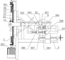
fig. 8 is a top view structural diagram of the present invention.
In the figure: 1. a frame, 2, a first guide rod, 21, a first slide block, 22, a sleeve, 23, a rotary drum, 24, a polishing head, 241, a cup-shaped polishing head, 25, a spline shaft, 26, a guide wheel, 261, a gear ring, 262, a first bevel gear, 263, a motor, 264, a fixed seat, 265, a rotary shaft, 266, a third bevel gear, 267, a fourth bevel gear, 268, a second bevel gear, 3, a main shaft, 31, a second guide rod, 32, a second slide block, 4, a first shaft sleeve, 41, a first driving rod, 42, a second shaft sleeve, 421, an arc-shaped plate, 422, a driving lever, 43, a second driving rod, 5, a guide rail, 51, a base, 52, a first screw rod, 53, a first hand wheel, 54, a fixed plate, 55, a first push rod, 56, a connecting rod, 57, a second push rod, 58, a connecting plate, 581, a driving plate, 5811, a driving groove, 58111, a rotary groove section, 58112, a linear groove section, 582, a guide rod, 583, a limit block, a spring 585, a limit plate 584, 586. an adjusting block 587, a second screw rod 588 and a second hand wheel.
Detailed Description
The technical solutions in the implementation of the present invention will be made clear and fully described below with reference to the accompanying drawings, and the described embodiments are only a part of the embodiments of the present invention, but not all of the embodiments. All other embodiments, which can be derived by a person skilled in the art from the embodiments of the present invention without making any creative effort, shall fall within the protection scope of the present invention.
Example 1
As shown in fig. 1 to 8, a machine tool for grinding spherical surfaces provided by embodiment 1 of the present invention includes a first guide bar 2 vertically fixed on a frame 1 and a main shaft 3 rotatably mounted on the frame 1, one end of the main shaft 3 near the first guide bar 2 is fixedly connected with a second guide bar 31 perpendicular to the first guide bar 2, the second guide bar 31 is not in contact with the first guide bar 2, and the main shaft 3 is perpendicular to both the first guide bar 2 and the second guide bar 31; a first shaft sleeve 4 and a second shaft sleeve 42 are slidably mounted on the main shaft 3, a first guide rod 2 is slidably mounted with two first sliders 21, a second guide rod 31 is slidably mounted with two second sliders 32, two first drive rods 41 which are perpendicular to each other are symmetrically inserted into the first shaft sleeve 4, the two first drive rods 41 are respectively fixedly connected with the two first sliders 21, two second drive rods 43 which are perpendicular to each other are symmetrically inserted into the second shaft sleeve 42, and the two second drive rods 43 are respectively fixedly connected with the two second sliders 32, as can be seen from fig. 5 and 8, the two first sliders 21 are symmetrically arranged on two sides of the axial lead of the main shaft 3, the two second sliders 32 are also symmetrically arranged on two sides of the axial lead of the main shaft 3, and the first drive rods 41, the first guide rod 2 and the main shaft 3 form a right-angled isosceles triangle, so that when the first shaft sleeve 4 moves on the main shaft 3, the first sliders 21 will move on the first guide rod 2 by the same distance, similarly, when the second sleeve 42 moves on the main shaft 3, the second slider 32 will also move on the second guide rod 582 by the same distance.
The two first sliding blocks 21 and the two second sliding blocks 32 are respectively provided with a sleeve 22, the sleeve 22 is rotatably provided with a rotating drum 23, one end of the rotating drum 23 is fixedly provided with a polishing head 24, the polishing head 24 is a cup-shaped polishing head 241, and the cup-shaped polishing head 241 can be used for polishing and can also be used as a clamping tool, so that a ball can be stably clamped. When the first shaft sleeve 4 and/or the second shaft sleeve 42 move towards the first guide rod 2, at least one pair of grinding heads 24 can clamp the spherical blank. A spline shaft 25 is movably inserted into one end of the rotary drum 23 far away from the polishing head 24, a driving mechanism for driving the spline shaft 25 to rotate and an adjusting mechanism for driving the first shaft sleeve 4 and the second shaft sleeve 42 to move on the main shaft 3 are arranged on the frame 1, and the adjusting mechanism can drive the second shaft sleeve 42 to rotate.
The adjustment mechanism may be a combination of a power-driven push rod or other linear reciprocating power mechanism capable of controlling the stroke and a motor 263, and the driving mechanism may be a motor 263, for example, a motor 263 for each spline shaft 25.
By arranging the driving mechanism and the adjusting mechanism, when the polishing device is used, the first shaft sleeve 4 can be driven to move towards the first guide rod 2 firstly, so that the first two sliding blocks 21 can move relatively, the two polishing heads 24 on the first sliding blocks 21 can clamp the spherical rough blank, the driving mechanism is started to enable the polishing heads 24 to rotate at the moment to drive the spherical rough blank to rotate, then the second shaft sleeve 42 is driven to move towards the guide rod 582, because the two polishing heads 24 on the second sliding blocks 32 also rotate, the spherical rough blank can be polished after the polishing heads 24 on the second sliding blocks 32 contact the spherical rough blank, an included angle between the second guide rod 31 and the first guide rod 2 is changed by rotating the second shaft sleeve 42, the position of the spherical rough blank polished by the polishing heads 24 is changed, after partial surface of the spherical rough blank is polished, only the polishing heads 24 on the second sliding blocks 32 need to reset to clamp the spherical rough blank, the polishing head 24 on the first sliding block 21 is used for polishing the residual surface of the spherical rough blank, so that the whole spherical surface processing of the spherical rough blank can be completed, and the driving mechanism and the adjusting mechanism can realize automatic overturning and change of the polishing angle of the spherical rough blank through cooperative work of the driving mechanism and the adjusting mechanism according to the process through a control mechanism such as a single chip microcomputer in the whole process, so that manual operation is omitted, and the production efficiency is improved.
Example 2
On the basis of the embodiment 1, the invention further provides an embodiment 2, wherein the frame 1 is provided with four guide wheels 26, the driving mechanism comprises a gear ring 261 rotatably mounted on the guide wheels 26 of the frame 1, the axis of the main shaft 3 is vertical and passes through the center of the gear ring 261, as can be seen from fig. 1, the end parts of all the spline shafts 25 far away from the center of the gear ring 261 are connected with the first guide rod 2 or the second guide rod 31 through bearing seats, the bevel gears 262 meshed with the gear ring 261 are arranged at one ends of the spline shafts 25 on one of the first sliders 21 and the second sliders 32, and the steering synchronization mechanism matched with the gear ring 261 is arranged at one ends of the spline shafts 25 on the other sliders 21 and the second sliders 32. The frame 1 is provided with a motor 263, and the motor 263 can drive the whole driving mechanism to rotate by driving the gear ring 261, the spline shaft 25 or the bevel gear 262 to rotate. Because the polishing heads 24 on the two first sliders 21 or the two second sliders 32 are matched to clamp the spherical blank and drive the spherical blank to rotate, the rotation directions of the polishing heads 24 on the two first sliders 21 are the same, and the rotation directions of the polishing heads 24 on the two second sliders 32 are the same, so that a steering synchronization mechanism is required to change the rotation direction of the spline shaft 25 on the other side.
Specifically, the steering synchronization mechanism includes a fixing seat 264, a second bevel gear 268 fixedly installed on the spline shaft 25, and a rotating shaft 265 rotatably installed on the fixing seat 264, the two fixing seats 264 are respectively and fixedly connected with the frame 1 and the second guide rod 31, a third bevel gear 266 meshed with the gear ring 261 and a fourth bevel gear 267 meshed with the second bevel gear 268 are fixedly installed on the rotating shaft 265, the first bevel gear 262 and the third bevel gear 266 have the same size, and the second bevel gear 268 and the fourth bevel gear 267 have the same size, so that when the gear ring 261 rotates, the rotation speeds of all spline shafts 25 are the same, the rotation directions of the spline shafts 25 on the two mutually matched sliders 21 are the same, the rotation directions of the spline shafts 25 on the two mutually matched sliders 32 are the same, the spherical blanks can be clamped and driven to rotate, one motor 263 can drive the four spline shafts 25 to rotate, and the structure is practical, the cost is saved.
Example 3
On the basis of embodiment 1, in order to facilitate matching with polishing of spherical rough blanks with different diameters, the invention further provides embodiment 3, and specifically, the adjusting mechanism includes a guide rail 5 fixedly mounted on the frame 1 and parallel to the main shaft 3, a base 51 slidably mounted on the guide rail 5, and a first lead screw 52 rotatably mounted on the frame 1 and parallel to the guide rail 5, a first hand wheel 53 is arranged at an end of the first lead screw 52, the first lead screw 52 is in threaded fit with the base 51, a fixing plate 54 is arranged on the base 51, and a first push rod 55 for driving the first shaft sleeve 4 to move on the main shaft 3 and a second push rod 57 for driving the second shaft sleeve 42 to move on the main shaft 3 are arranged on the fixing plate 54. The output end of the first push rod 55 is fixedly connected with the first shaft sleeve 4 through a connecting rod 56. Therefore, the first screw rod 52 can rotate by rotating the first hand wheel 53, and the base 51 can move on the guide rail 5, so that the initial positions of the first shaft sleeve 4 and the second shaft sleeve 42 can be adjusted simultaneously to match spherical blanks with different diameters.
Furthermore, as the second guide rod 31 needs to be capable of rotating, so as to change the polishing position of the polishing head 24, the output end of the second push rod 57 is fixedly connected with a connecting plate 58, meanwhile, the second sleeve 42 is fixedly connected with a shift lever 422 and an arc plate 421 concentric with the spindle 3, the connecting plate 58 is fixedly connected with a guide rod 582 and a driving plate 581 matched with the shift lever 422, the cross section of the driving plate 581 is in an arc shape, a driving groove 5811 is formed in the driving plate 581, the driving groove 5811 comprises a rotating groove section 58111 and a linear groove section 58112 arranged on one side of the rotating groove section 58111 far away from the connecting plate 58, the linear groove section 58112 is communicated with the rotating groove section 58111, and when the shift lever 422 moves in the rotating groove section 58111, the driving plate 581 can drive the shift lever 422 to rotate. Guide rod 582 keeps away from the one end of connecting plate 58 and is provided with limiting plate 585, and slidable mounting has stopper 583 on the guide rod 582 between limiting plate 585 and the connecting plate 58, and stopper 583 cooperatees with arc 421, specifically is that stopper 583 can follow both sides and clip arc 421 to can drive arc 421 together to remove when stopper 583 removes, limiting plate 585 does not influence the rotation of arc 421 simultaneously. Spring 584 is sleeved on the guide rod 582 between the limiting block 583 and the connecting plate 58, an adjusting block 586 is arranged on the rack 1 on one side of the limiting block 583 close to the second guide rod 31, and when the limiting block 583 abuts against the adjusting block 586, the driving plate 581 can drive the shifting rod 422 to rotate. The position of the adjusting block 586 determines the polishing depth of the polishing head 24, as can be seen from fig. 5, when the second push rod 57 works, the spring 584 can push the second limit block 583 to move, that is, can push the second shaft sleeve 42 to move, so that the polishing head 24 gradually approaches to the spherical blank, when the second limit block 583 abuts against the adjusting block 586, the second shaft sleeve 42 reaches the limit position, that is, the preset polishing depth of the polishing head 24 is reached, at this time, under the action of the second push rod 57, the spring 584 is further compressed, the shift lever 422 enters the rotary groove section 58111 from the linear groove section 58112, because the rotary groove section 58111 has a certain angle, the shift lever 422 rotates along with the rotary groove section 58111, so as to realize the rotation of the second shaft sleeve 42, when the second shaft sleeve 42 rotates, the second drive rod 31 is driven by the second drive rod 43 to rotate together, so as to realize the change of the polishing angle range of the spherical blank.
In order to set the position of the adjusting block 586 conveniently, a second screw 587 is rotatably mounted on the fixing plate 54, a second hand wheel 588 is arranged at one end of the screw, the adjusting block 586 is in threaded fit with the second screw 587, and one side of the adjusting block 586 is in sliding fit with the fixing plate 54. Therefore, the second screw rod 587 can drive the adjusting block 586 to move by rotating the second hand wheel 588.
When in use: by rotating the first hand wheel 53, the position of the base 51 is changed, so that the positions of the first shaft sleeve 4 and the second shaft sleeve 42 on the main shaft 3 are changed, the relative initial positions of the four polishing heads 24 are changed, and spherical blanks with different diameters are matched. The second hand wheel 588 is rotated to determine the position of the adjustment block 586. Then, the spherical rough blank is placed on the polishing heads 24 on the first sliding block 21, the first push rod 55 is started, the two polishing heads 24 on the first guide rod 2 align the sphere centers of the spherical rough blank to the axis of the spindle 3 and clamp the spherical rough blank tightly, then the motor 263 is started, the gear ring 261 rotates, meanwhile, the four spline shafts 25 rotate under the driving of the driving mechanism, the polishing heads 24 on the first sliding block 21 drive the spherical rough blank to rotate, and the polishing heads 24 on the second sliding block 32 also rotate. At this time, the second push rod 57 is started, the second push stopper 583 is pushed to move until the second push rod abuts against the adjusting block 586, at this time, the polishing head 24 on the second slide block 32 is already in contact with the spherical blank and is polished to a predetermined depth, when the second push rod 57 is further pushed, the spring 584 is compressed, the driving plate 581 drives the shift lever 422 to rotate, so that the second guide rod 31 rotates, the relative angle between the polishing head 24 on the second slide block 32 and the spherical blank is changed, and most of the surface of the spherical blank is polished. Then, the second push rod 57 can be retracted, the polishing head 24 on the second slider 32 can rotate to the original position, the motor 263 is stopped, the polishing head 24 on the second slider 32 can clamp the spherical rough blank, the motor 263 is started, the first push rod 55 is started, the polishing head 24 on the first slider 21 can polish the rest of the spherical rough blank, in the process, the driving plate 581 can drive the shift lever 422 to rotate, the polishing head 24 on the first slider 21 can polish all the surfaces of the spherical rough blank which are not polished, polishing of all the surfaces of the spherical rough blank is further achieved, manual disassembly and assembly of workers are not needed in the process to change the position of the spherical rough blank, and the processing efficiency is high.
It will be evident to those skilled in the art that the invention is not limited to the details of the foregoing illustrative embodiments, and that the present invention may be embodied in other specific forms without departing from the spirit or essential attributes thereof. The present embodiments are therefore to be considered in all respects as illustrative and not restrictive, the scope of the invention being indicated by the appended claims rather than by the foregoing description, and all changes which come within the meaning and range of equivalency of the claims are therefore intended to be embraced therein. Any reference sign in a claim should not be construed as limiting the claim concerned.
Furthermore, it should be understood that although the present description refers to embodiments, not every embodiment may contain only a single embodiment, and such description is for clarity only, and those skilled in the art should make the description as a whole, and the embodiments may be appropriately combined to form other embodiments understood by those skilled in the art.
Claims (8)
1. A machine tool for grinding spherical surfaces is characterized by comprising a first guide rod (2) arranged on a rack (1) and a main shaft (3) rotatably installed on the rack (1), wherein one end, close to the first guide rod (2), of the main shaft (3) is fixedly connected with a second guide rod (31) perpendicular to the first guide rod (2), and the main shaft (3) is perpendicular to the first guide rod (2) and the second guide rod (31); the grinding machine is characterized in that two first sliding blocks (21) are slidably mounted on the first guide rod (2), two second sliding blocks (32) are slidably mounted on the second guide rod (31), a first shaft sleeve (4) and a second shaft sleeve (42) are slidably mounted on the main shaft (3), two mutually perpendicular driving rods (41) are symmetrically inserted in the first shaft sleeve (4), the two driving rods (41) are fixedly connected with the two first sliding blocks (21) respectively, two mutually perpendicular driving rods (43) are symmetrically inserted in the second shaft sleeve (42), the two driving rods (43) are fixedly connected with the two second sliding blocks (32) respectively, a sleeve (22) is arranged on each of the two first sliding blocks (21) and the two second sliding blocks (32), a rotary drum (23) is rotatably mounted in the sleeve (22), and a grinding head (24) is fixedly mounted at one end of the rotary drum (23), a spline shaft (25) is movably inserted into one end, far away from the polishing head (24), of the rotary drum (23), a driving mechanism used for driving the spline shaft (25) to rotate and an adjusting mechanism used for driving the first shaft sleeve (4) and the second shaft sleeve (42) to move on the main shaft (3) are arranged on the rack (1), and the adjusting mechanism can drive the second shaft sleeve (42) to rotate.
2. A machine tool for grinding spherical surfaces according to claim 1, characterized in that the drive mechanism comprises a gear ring (261) rotatably mounted on the machine frame (1), the axis of the spindle (3) is perpendicular to and passes through the center of the gear ring (261), one end of the spline shaft (25) on one of the first slider (21) and the second slider (32) is provided with a first bevel gear (262) engaged with the gear ring (261), and one end of the spline shaft (25) on the other of the first slider (21) and the second slider (32) is provided with a steering synchronization mechanism engaged with the gear ring (261).
3. The machine tool for grinding spherical surfaces according to claim 2, wherein the steering synchronization mechanism comprises a fixed seat (264), a bevel gear II (268) fixedly mounted on the spline shaft (25) and a rotating shaft (265) rotatably mounted on the fixed seat (264), a bevel gear III (266) meshed with the gear ring (261) and a bevel gear IV (267) meshed with the bevel gear II (268) are fixedly mounted on the rotating shaft (265), the sizes of the bevel gear I (262) and the bevel gear III (266) are the same, and the sizes of the bevel gear II (268) and the bevel gear IV (267) are the same.
4. A machine tool for grinding spherical surfaces according to claim 1, characterized in that the adjusting mechanism comprises a guide rail (5) fixedly mounted on the machine frame (1) and parallel to the main shaft (3), a base (51) slidably mounted on the guide rail (5), and a first screw rod (52) rotatably mounted on the machine frame (1) and parallel to the guide rail (5), the first screw rod (52) is in threaded fit with the base (51), a fixing plate (54) is arranged on the base (51), and a first push rod (55) for driving the first sleeve (4) to move on the main shaft (3) and a second push rod (57) for driving the second sleeve (42) to move on the main shaft (3) are arranged on the fixing plate (54).
5. The machine tool for grinding the spherical surface according to claim 4, characterized in that a connecting plate (58) is arranged at the output end of the second push rod (57), a deflector rod (422) and an arc-shaped plate (421) concentric with the main shaft (3) are fixedly connected to the second shaft sleeve (42), a guide rod (582) and a driving plate (581) matched with the deflector rod (422) are arranged on the connecting plate (58), a limit plate (585) is arranged at one end, far away from the connecting plate (58), of the guide rod (582), a limit block (583) is slidably mounted on the guide rod (582) between the limit plate (585) and the connecting plate (58), the limit block (583) is matched with the arc-shaped plate (421), a spring (584) is sleeved on the guide rod (582) between the limit block (583) and the connecting plate (58), and an adjusting block (586) is arranged on the machine frame (1) at one side, close to the second guide rod (31), of the limit block (583), when the limiting block (583) abuts against the adjusting block (586), the driving plate (581) can drive the shifting lever (422) to rotate.
6. A machine tool for grinding spherical surfaces according to claim 5, characterized in that a driving groove (5811) is provided on said driving plate (581), said driving groove (5811) comprising a rotary groove section (58111) and a linear groove section (58112) provided on the side of the rotary groove section (58111) remote from the connecting plate (58), the linear groove section (58112) communicating with the rotary groove section (58111), said driving plate (581) being capable of driving the rotation of the deflector rod (422) when said deflector rod (422) moves in the rotary groove section (58111).
7. The machine tool for grinding spherical surfaces according to claim 5, characterized in that a second screw rod (587) is rotatably mounted on the fixing plate (54), the adjusting block (586) is in threaded engagement with the second screw rod (587), and one side of the adjusting block (586) is in sliding engagement with the fixing plate (54).
8. A machine for grinding spherical surfaces according to claim 1, characterized in that the ends of the grinding heads (24) are cup-shaped grinding heads (241).
Priority Applications (1)
| Application Number | Priority Date | Filing Date | Title |
|---|---|---|---|
| CN202210188930.9A CN114454030A (en) | 2022-02-28 | 2022-02-28 | Machine tool for grinding spherical surface |
Applications Claiming Priority (1)
| Application Number | Priority Date | Filing Date | Title |
|---|---|---|---|
| CN202210188930.9A CN114454030A (en) | 2022-02-28 | 2022-02-28 | Machine tool for grinding spherical surface |
Publications (1)
| Publication Number | Publication Date |
|---|---|
| CN114454030A true CN114454030A (en) | 2022-05-10 |
Family
ID=81415497
Family Applications (1)
| Application Number | Title | Priority Date | Filing Date |
|---|---|---|---|
| CN202210188930.9A Withdrawn CN114454030A (en) | 2022-02-28 | 2022-02-28 | Machine tool for grinding spherical surface |
Country Status (1)
| Country | Link |
|---|---|
| CN (1) | CN114454030A (en) |
Cited By (1)
| Publication number | Priority date | Publication date | Assignee | Title |
|---|---|---|---|---|
| CN115091317A (en) * | 2022-08-24 | 2022-09-23 | 苏州耀康医疗科技有限公司 | A needle cap surface burnishing and polishing device for insulin pen research and development production |
-
2022
- 2022-02-28 CN CN202210188930.9A patent/CN114454030A/en not_active Withdrawn
Cited By (1)
| Publication number | Priority date | Publication date | Assignee | Title |
|---|---|---|---|---|
| CN115091317A (en) * | 2022-08-24 | 2022-09-23 | 苏州耀康医疗科技有限公司 | A needle cap surface burnishing and polishing device for insulin pen research and development production |
Similar Documents
| Publication | Publication Date | Title |
|---|---|---|
| CN202701924U (en) | Grinding machine for inner circle of blank | |
| CN114227024B (en) | Intelligent laser cutting device | |
| CN210524023U (en) | Straight bevel gear grinding equipment | |
| CN116160363B (en) | Clamping device for bearing polishing | |
| CN114454030A (en) | Machine tool for grinding spherical surface | |
| CN210548589U (en) | Straight bevel gear grinding machine | |
| CN110549197B (en) | Bamboo tube wine end face repairing device | |
| CN113635189B (en) | Machining process for surface polishing and grinding system of forging and casting | |
| CN218461685U (en) | Full-automatic sharpening equipment for high-precision milling cutter | |
| CN208961715U (en) | A kind of high-speed rail train C-shaped support casting grinding equipment | |
| CN203236320U (en) | Grinding machine for grinded cycloid gear | |
| CN108568723A (en) | Mirrors fine-grinding and polishing device | |
| CN112059770A (en) | Outer edge reprocessing and cleaning device for gear production | |
| CN116197771B (en) | Ball valve processing equipment | |
| CN112207686A (en) | Grinding machine for electronic part production and using method | |
| CN220427751U (en) | Be used for car bent axle processing to use surface grinding device | |
| CN219131902U (en) | Acrylic plate surface polishing device | |
| CN216504064U (en) | Cam rough blank processing tool | |
| CN219666010U (en) | Grinding device is used in valve pocket production | |
| CN112548753B (en) | Round piece corner chamfer device of polishing | |
| CN220007264U (en) | Sharpening machine capable of adjusting angle | |
| CN215317709U (en) | Be used for diesel engine core to press from both sides valve opening grinding machine frock | |
| CN219901530U (en) | Grinding device is used in steel ball production | |
| CN219113590U (en) | Self-aligning roller bearing numerically controlled grinder | |
| CN220260649U (en) | Abrasive grinding tool machining clamping device convenient to adjust |
Legal Events
| Date | Code | Title | Description |
|---|---|---|---|
| PB01 | Publication | ||
| PB01 | Publication | ||
| SE01 | Entry into force of request for substantive examination | ||
| SE01 | Entry into force of request for substantive examination | ||
| WW01 | Invention patent application withdrawn after publication |
Application publication date: 20220510 |
|
| WW01 | Invention patent application withdrawn after publication |