CN114450550A - Correction method, correction program, and information processing system - Google Patents
Correction method, correction program, and information processing system Download PDFInfo
- Publication number
- CN114450550A CN114450550A CN201980100928.8A CN201980100928A CN114450550A CN 114450550 A CN114450550 A CN 114450550A CN 201980100928 A CN201980100928 A CN 201980100928A CN 114450550 A CN114450550 A CN 114450550A
- Authority
- CN
- China
- Prior art keywords
- point cloud
- pixels
- correction
- coordinate
- coordinate information
- Prior art date
- Legal status (The legal status is an assumption and is not a legal conclusion. Google has not performed a legal analysis and makes no representation as to the accuracy of the status listed.)
- Pending
Links
- 230000010365 information processing Effects 0.000 title claims abstract description 61
- 238000012937 correction Methods 0.000 title claims description 103
- 238000000034 method Methods 0.000 title claims description 72
- 238000005259 measurement Methods 0.000 claims abstract description 22
- 238000012545 processing Methods 0.000 claims description 88
- 238000010586 diagram Methods 0.000 description 46
- 210000000988 bone and bone Anatomy 0.000 description 27
- 230000002093 peripheral effect Effects 0.000 description 11
- 238000011156 evaluation Methods 0.000 description 9
- 238000004891 communication Methods 0.000 description 8
- 230000006870 function Effects 0.000 description 7
- 238000007796 conventional method Methods 0.000 description 6
- 230000000694 effects Effects 0.000 description 4
- 238000006243 chemical reaction Methods 0.000 description 3
- 239000000284 extract Substances 0.000 description 3
- 230000007704 transition Effects 0.000 description 3
- 230000009189 diving Effects 0.000 description 2
- 238000005401 electroluminescence Methods 0.000 description 2
- 238000012854 evaluation process Methods 0.000 description 2
- 230000010354 integration Effects 0.000 description 2
- 102220171488 rs760746448 Human genes 0.000 description 2
- 230000002159 abnormal effect Effects 0.000 description 1
- 238000000605 extraction Methods 0.000 description 1
- 239000004973 liquid crystal related substance Substances 0.000 description 1
- 238000013507 mapping Methods 0.000 description 1
- 239000004065 semiconductor Substances 0.000 description 1
- 230000009182 swimming Effects 0.000 description 1
Images


Classifications
-
- G06T5/70—
-
- G—PHYSICS
- G01—MEASURING; TESTING
- G01B—MEASURING LENGTH, THICKNESS OR SIMILAR LINEAR DIMENSIONS; MEASURING ANGLES; MEASURING AREAS; MEASURING IRREGULARITIES OF SURFACES OR CONTOURS
- G01B11/00—Measuring arrangements characterised by the use of optical techniques
-
- G—PHYSICS
- G06—COMPUTING; CALCULATING OR COUNTING
- G06T—IMAGE DATA PROCESSING OR GENERATION, IN GENERAL
- G06T7/00—Image analysis
- G06T7/10—Segmentation; Edge detection
- G06T7/12—Edge-based segmentation
-
- G—PHYSICS
- G06—COMPUTING; CALCULATING OR COUNTING
- G06T—IMAGE DATA PROCESSING OR GENERATION, IN GENERAL
- G06T7/00—Image analysis
- G06T7/10—Segmentation; Edge detection
- G06T7/13—Edge detection
-
- G—PHYSICS
- G06—COMPUTING; CALCULATING OR COUNTING
- G06T—IMAGE DATA PROCESSING OR GENERATION, IN GENERAL
- G06T7/00—Image analysis
- G06T7/10—Segmentation; Edge detection
- G06T7/194—Segmentation; Edge detection involving foreground-background segmentation
-
- G—PHYSICS
- G06—COMPUTING; CALCULATING OR COUNTING
- G06T—IMAGE DATA PROCESSING OR GENERATION, IN GENERAL
- G06T7/00—Image analysis
- G06T7/50—Depth or shape recovery
- G06T7/521—Depth or shape recovery from laser ranging, e.g. using interferometry; from the projection of structured light
-
- G—PHYSICS
- G06—COMPUTING; CALCULATING OR COUNTING
- G06T—IMAGE DATA PROCESSING OR GENERATION, IN GENERAL
- G06T7/00—Image analysis
- G06T7/70—Determining position or orientation of objects or cameras
- G06T7/73—Determining position or orientation of objects or cameras using feature-based methods
- G06T7/75—Determining position or orientation of objects or cameras using feature-based methods involving models
-
- G—PHYSICS
- G01—MEASURING; TESTING
- G01S—RADIO DIRECTION-FINDING; RADIO NAVIGATION; DETERMINING DISTANCE OR VELOCITY BY USE OF RADIO WAVES; LOCATING OR PRESENCE-DETECTING BY USE OF THE REFLECTION OR RERADIATION OF RADIO WAVES; ANALOGOUS ARRANGEMENTS USING OTHER WAVES
- G01S17/00—Systems using the reflection or reradiation of electromagnetic waves other than radio waves, e.g. lidar systems
- G01S17/88—Lidar systems specially adapted for specific applications
- G01S17/89—Lidar systems specially adapted for specific applications for mapping or imaging
-
- G—PHYSICS
- G06—COMPUTING; CALCULATING OR COUNTING
- G06T—IMAGE DATA PROCESSING OR GENERATION, IN GENERAL
- G06T2207/00—Indexing scheme for image analysis or image enhancement
- G06T2207/10—Image acquisition modality
- G06T2207/10028—Range image; Depth image; 3D point clouds
-
- G—PHYSICS
- G06—COMPUTING; CALCULATING OR COUNTING
- G06T—IMAGE DATA PROCESSING OR GENERATION, IN GENERAL
- G06T2207/00—Indexing scheme for image analysis or image enhancement
- G06T2207/20—Special algorithmic details
- G06T2207/20172—Image enhancement details
- G06T2207/20192—Edge enhancement; Edge preservation
-
- G—PHYSICS
- G06—COMPUTING; CALCULATING OR COUNTING
- G06T—IMAGE DATA PROCESSING OR GENERATION, IN GENERAL
- G06T2207/00—Indexing scheme for image analysis or image enhancement
- G06T2207/30—Subject of image; Context of image processing
- G06T2207/30196—Human being; Person
Abstract
The information processing device generates a distance image based on measurement data of the 3D sensor. The information processing apparatus specifies a plurality of 1 st pixels corresponding to a point cloud of an outline of a subject among pixels included in a range image. The information processing device identifies a plurality of 2 nd pixels included in a predetermined range from the plurality of 1 st pixels among the pixels included in the range image. The information processing device corrects 1 st coordinate information of the 1 st point cloud corresponding to the 1 st pixels based on 2 nd coordinate information of the 2 nd point cloud corresponding to the 2 nd pixels in the measurement data. The information processing apparatus outputs coordinate information of a point cloud constituting a subject including a 1 st point cloud obtained by correcting the 1 st coordinate information.
Description
Technical Field
The present invention relates to a calibration method and the like.
Background
There is a technique of measuring a three-dimensional point cloud of a subject using a laser sensor equidistance measuring device to recognize the posture of the subject. In the following description, a laser sensor for measuring a three-dimensional point cloud of a subject will be simply referred to as a "sensor". The information of the three-dimensional point cloud measured by the sensor is used for various processes at the subsequent stage.
Here, when the three-dimensional point cloud of the object is measured by the sensor, edge noise occurs in a depth direction from an actual position in a contour portion of the object. Fig. 23 is a diagram for explaining an example of edge noise. As shown in fig. 23, the sensor 10 measures a three-dimensional point cloud 1a when measuring the three-dimensional point cloud of the object 1. The three-dimensional point cloud 1a contains edge noise 1 b.
The edge noise 1b is generated in a state where the laser light passes over the contour portion of the object 1 at the time of measurement. That is, although the edge noise 1b is a point representing the contour of the object 1, the distance value in the depth direction is measured as a position farther than the distance value of the object 1, and is farther than the three-dimensional point cloud 1a constituting the object 1.
When the three-dimensional point cloud contains edge noise, accuracy is lowered in processing at a later stage, and therefore, processing of the edge noise is required. As conventional techniques for processing edge noise, there are, for example, conventional technique 1 and conventional technique 2.
As shown in fig. 24, with respect to the point 2a, many points exist around the point 2a, and the point cloud density is equal to or higher than the threshold value. Thus, prior art 1 leaves point 2 a. On the other hand, regarding the point 2b, there are fewer points around the point 2b, and the point cloud density is smaller than the threshold value. Therefore, prior art 1 deletes point 2 b. The related art 1 repeatedly performs the above-described processing for each point of the three-dimensional point cloud 1a, thereby deleting the edge noise 1 b.
The prior art 2 is a technique of correcting edge noise. In prior art 2, 2 RGB-based stereoscopic images are captured, and the contour of an object is extracted in advance based on the stereoscopic images. In conventional technique 2, when a depth image of a subject is measured by a sensor, a contour position on the depth image is specified from a contour position of the subject using a stereo image, and a value of the depth image is corrected with 2 points crossing the contour as a reference.
Documents of the prior art
Patent document
Patent document 1: international publication No. 2019/087404
Patent document 2: japanese patent laid-open publication No. 2012-79251
Disclosure of Invention
Problems to be solved by the invention
The prior art 1 is a technique of deleting points based on point cloud density, but the number of three-dimensional point clouds that can be used in the subsequent processing is reduced. For example, when the resolution of the sensor is low or when the distance between the object and the sensor is large, the number of three-dimensional point clouds is inherently small. Further, the observable number of three-dimensional point clouds corresponding to a portion (for example, an arm of a human being) where the area of the subject that can be observed from the 3D sensor is small. Therefore, when simply removing edge noise related to the contour of the object, the contour and shape of the object cannot be accurately maintained only in the remaining point cloud.
Fig. 25 is a diagram for explaining a problem of the prior art 1. When the point is deleted based solely on the point cloud density, not only the edge noise 1b but also the point cloud 1c is deleted. This is because there are fewer surrounding points of the point cloud 1c and the point cloud density is less than the threshold value. By deleting the point cloud 1c that does not match the edge noise, the number of the three-dimensional point clouds 1a is reduced, and points that can be used in the processing at the later stage are limited. The point cloud 1c is a point cloud that matches the arm of a human being as a subject, and the original arm of the subject is not maintained by deleting the point cloud 1 c.
Further, although the conventional technique 2 is a technique for correcting edge noise, it is assumed that the contour of a subject is specified by a stereo image, unlike a depth image, although the number of three-dimensional point clouds can be maintained. Therefore, it is difficult to correct edge noise in a situation where a stereoscopic image cannot be used.
In the aspect 1, an object of the present invention is to provide a correction method, a correction program, and an information processing system capable of leaving a point corresponding to edge noise in noise of a three-dimensional point cloud measured by a sensor as a point of an outline of an object.
Means for solving the problems
In the 1 st aspect, the computer executes the following processing. The computer generates a distance image based on the measurement data of the 3D sensor. The computer specifies a plurality of 1 st pixels corresponding to a point cloud of an outline of a subject among pixels included in a range image. The computer specifies a plurality of 2 nd pixels included in a predetermined range from the plurality of 1 st pixels among the pixels included in the range image. The computer corrects 1 st coordinate information of the 1 st point cloud corresponding to the 1 st pixels based on 2 nd coordinate information of the 2 nd point cloud corresponding to the 2 nd pixels in the measurement data. The computer outputs coordinate information of a point cloud constituting a subject including the 1 st point cloud after correcting the 1 st coordinate information.
ADVANTAGEOUS EFFECTS OF INVENTION
It is possible to leave, as a point of the contour of the object, a point corresponding to the edge noise in the noise of the three-dimensional point cloud measured by the sensor.
Drawings
Fig. 1 is a diagram showing an example of an information processing system according to the present embodiment.
Fig. 2 is a diagram for explaining an example of processing of the information processing system according to the present embodiment.
Fig. 3 is a diagram for explaining an example of the background difference.
Fig. 4 is a diagram for explaining an example of the correction processing.
Fig. 5 is a diagram illustrating an example of bone recognition.
Fig. 6 is a diagram illustrating an example of point cloud clustering.
Fig. 7 is a diagram showing an example of fitting.
Fig. 8 is a functional block diagram showing the structure of the information processing apparatus of the present embodiment.
Fig. 9 is a diagram for explaining the focal length fx in the x-axis direction.
Fig. 10 is a diagram for explaining the focal length fy in the y-axis direction.
Fig. 11 is a diagram illustrating an example of the correction processing section.
Fig. 12 is a diagram for explaining the process of generating a 2.5D image.
Fig. 13 is a diagram for explaining the process of determining the 1 st pixel.
Fig. 14 is a diagram showing the relationship between w and z used in the calculation of the distance ix.
Fig. 15 is a diagram showing the relationship of h and z used in the calculation of the distance iy.
Fig. 16 is a diagram (1) for explaining the process of performing the correction.
Fig. 17 is a diagram (2) for explaining the process of performing the correction.
Fig. 18 is a diagram for explaining the relationship between points before and after correction.
Fig. 19 is a flowchart (1) showing the processing procedure of the correction processing section of the present embodiment.
Fig. 20 is a flowchart (2) showing the processing procedure of the correction processing section of the present embodiment.
Fig. 21 is a diagram for explaining the effects of the present embodiment.
Fig. 22 is a diagram showing an example of a hardware configuration of a computer that realizes the same function as the information processing apparatus.
Fig. 23 is a diagram for explaining an example of edge noise.
Fig. 24 is a diagram for explaining related art 1.
Fig. 25 is a diagram for explaining a problem of the prior art 1.
Detailed Description
Hereinafter, embodiments of a correction method, a correction program, and an information processing system according to the present invention will be described in detail with reference to the drawings. The present invention is not limited to the examples.
Examples
Fig. 1 is a diagram showing an example of an information processing system according to the present embodiment. As shown in fig. 1, the information processing system has sensors 11a, 11b, 11c, 11d and an information processing apparatus 100. The sensors 11a to 11d are connected to the information processing device 100 by wire or wirelessly.
In the present embodiment, the subject 1 is assumed to perform on an instrument as an example, but the present invention is not limited to this. For example, the subject 1 may perform in a place where no instrument is present, or may perform an action other than the performance.
The sensor 11a is a measuring device (laser sensor) that measures the distance between the point cloud constituting the object 1 and the sensor 11 a. The sensor 11a outputs data of the distance image as the measurement result to the information processing apparatus 100. For example, the sensor 11a performs raster scanning, and the distance between the point cloud and the sensor 11a is measured.
The description of the sensors 11b to 11d is the same as that of the sensor 11 a. In the following description, the sensors 11a to 11d are collectively referred to as "sensors 11".
Fig. 2 is a diagram for explaining an example of processing of the information processing apparatus of the present embodiment. For example, the information processing apparatus 100 executes the processing of steps S10 to S15 described below.
The process (background difference) of step S10 will be described. The information processing apparatus 100 removes background noise by calculating a difference between the background image and the range image acquired from the sensor 11, and generates data of the range image from which the background noise is removed. The background image is a distance image measured by the sensor 11 in a situation where the subject 1 is not present.
Fig. 3 is a diagram for explaining an example of the background difference. As shown in fig. 3, the information processing apparatus 100 generates a distance image 12C by calculating a difference between the background image 12B and the distance image 12A.
The information processing apparatus 100 converts the data of the distance image 12C into three-dimensional point cloud data 20A. The three-dimensional point cloud data 20A converts the relationship between the points included in the distance image 12C and the distance into the relationship between the points and the coordinates of the three-dimensional orthogonal coordinate system. For example, the three-dimensional orthogonal coordinate system includes an x-axis, a y-axis, and a z-axis, and the z-axis is an axis in the depth direction of the sensor 11. In the following description, the coordinates of the three-dimensional orthogonal coordinate system are referred to as "three-dimensional coordinates".
The processing (correction processing) of step S11 will be described. The information processing apparatus 100 generates the three-dimensional point cloud data 20B by correcting edge noise included in the three-dimensional point cloud data 20A.
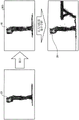
Fig. 4 is a diagram for explaining an example of the correction processing. As shown in fig. 4, the information processing apparatus 100 generates three-dimensional point cloud data 20B by performing correction processing on the three-dimensional point cloud data 20A. When the three-dimensional point cloud data 20A and the three-dimensional point cloud data 20B are compared, in the contour portion 13, the coordinates of the edge noise are corrected to be near the surface of the object or instrument. The detailed description about the correction processing will be described later.
The processing (2.5D (Dimension) conversion) in step S12 will be described. The information processing apparatus 100 generates 2.5D image data 21 by projecting the three-dimensional point cloud data 20B onto a two-dimensional map. Each pixel of the image data 21 corresponds to a point cloud of the three-dimensional point cloud data 20B. The z-axis value of the corresponding point is set in the pixel of the image data 21.
The processing (recognition processing) of step S13A will be described. The information processing apparatus 100 generates a joint heat map 22 by inputting 2.5D image data 21 to a learning model learned in advance. The joint thermal map 22 is information indicating the positions of the joints of the subject 1.
The processing (point cloud integration) of step S13B will be described. The information processing apparatus 100 integrates the three-dimensional point cloud data 20B (a plurality of three-dimensional point cloud data 20B measured by each sensor 11 and a plurality of three-dimensional point cloud data 20B subjected to the correction processing) to generate one three-dimensional point cloud data 20C.
The information processing apparatus 100 may execute the process of step S13A and the process of step S13B in parallel.
The processing (bone recognition) of step S14A will be described. The information processing apparatus 100 generates the bone recognition result 23 based on the positions of the joints shown in the joint heat map 22. For example, the bone recognition result 23 is information obtained by connecting the coordinates of the respective joints.
Fig. 5 is a diagram illustrating an example of bone recognition. In the example shown in fig. 5, a bone recognition result 23 obtained by combining three-dimensional point cloud data is shown. For example, if noise (noise of a floor mat, etc.) remains under the feet of the subject 1, the bone positions of the below-knee and the toe become abnormal in the bone recognition result 23.
The processing (point cloud clustering) of step S14B will be described. The information processing apparatus 100 classifies the three-dimensional point cloud data 20C into a plurality of clusters by performing point cloud clustering. The information processing apparatus 100 deletes, as noise, a point cloud included in a cluster in which the number of points of a point cloud cluster is smaller than a threshold value among a plurality of clusters. Further, the point cloud included in a cluster in which the volume of a polyhedron formed by point cloud clusters is smaller than a threshold value, not the number of points of the point cloud clusters, may be deleted as noise.
Fig. 6 is a diagram illustrating an example of point cloud clustering. As shown in fig. 6, point cloud clustering is performed on the three-dimensional point cloud data 20C, removing the noise 14, thereby generating three-dimensional point cloud data 20D.
The information processing apparatus 100 may execute the process of step S14A and the process of step S14B in parallel.
The processing (fitting) of step S15 will be described. Fig. 7 is a diagram showing an example of fitting. As shown in fig. 7, the information processing device 100 applies the cylinder model 16 to the bone recognition result 23 described in step S14A, and sets an initial position. The cylinder model is data of a model in which each part of the object 1 is expressed by a cylinder (or an elliptic cylinder, or the like). The information processing apparatus 100 changes the angle of the connecting portion of each cylinder of the cylinder model 16 little by little, and performs adjustment (fitting) in which the distance between the surface of the cylinder model and each point of the three-dimensional point cloud data 20D is close to each other.
The information processing device 100 generates a bone model 24 obtained by connecting the axes of the fitted cylindrical models 16.
The information processing device 100 repeatedly executes the processing of steps S10 to S15 and the processing of generating the bone model 24 every time distance image data is acquired from the sensor 11. The information processing device 100 outputs the bone model 24 in time series, and performs specification, scoring, and the like of various competitions based on the transition of the joint position of the bone model 24 at each time.
Next, an example of the configuration of the information processing apparatus 100 shown in fig. 1 will be described. Fig. 8 is a functional block diagram showing the structure of the information processing apparatus of the present embodiment. As shown in fig. 8, the information processing apparatus 100 includes a communication unit 110, an input unit 120, a display unit 130, a storage unit 140, and a control unit 150.
The communication unit 110 is a processing unit that receives data of a distance image from the sensor 11 shown in fig. 1. The communication unit 110 outputs the received distance image data to the control unit 150. The communication unit 110 is an example of a communication device.
The input unit 120 is an input device that inputs various information to the information processing device 100. The input section 120 corresponds to a keyboard, a mouse, a touch panel, and the like. For example, the user operates the input unit 120 to request a display screen to be displayed.
The display unit 130 is a display device that displays information output from the control unit 150. For example, the display unit 130 displays the skill identification, the score result, and the like of each game. The display portion 130 corresponds to a liquid crystal display, an organic EL (Electro-Luminescence) display, a touch panel, or the like.
The storage unit 140 includes a background image table 141, a measurement table 142, and sensor parameters 143. The storage unit 140 corresponds to a semiconductor Memory element such as a RAM (Random Access Memory) or a Flash Memory, or a storage device such as a Hard Disk Drive (HDD).
The background image table 141 is a table in which data (distance image data) of background images measured by the respective sensors 11a to 11d are stored in a state where the subject 1 is not present.
The measurement table 142 is a table that stores data of distance images measured by the sensors 11a to 11d, respectively, in a state where the subject 1 is present.
The sensor parameters 143 include parameters of the sensors 11a to 11d, respectively. For example, the sensor parameters 143 include the field angles θ x and θ y of the x-axis and the y-axis, and the focal lengths fx and fy of the x-axis and the y-axis. In addition, the sensor parameters 143 include width and height.
Fig. 9 is a diagram for explaining the focal length fx in the x-axis direction. Fig. 9 shows a state in which the sensor 11 is viewed from above. For example, the relationship between the focal length fx and the field angle θ x is expressed by equation (1). In the formula (1), width is a preset horizontal width and corresponds to the number of pixels in the horizontal direction (i-axis direction) of a 2.5D image described later.
fx=width/(2*tan(θx/2))···(1)
Fig. 10 is a diagram for explaining the focal length fy in the y-axis direction. Fig. 10 shows the case where the sensor 11 is viewed from the lateral direction. For example, the relationship between the focal length fy and the angle of view θ y is expressed by equation (2). In the equation (2), height is a predetermined height and corresponds to the number of pixels in the vertical direction (j-axis direction) of a 2.5D image described later.
fy=height/(2*tan(θy/2))···(2)
The explanation returns to fig. 8. The control unit 150 includes an acquisition unit 151, a correction processing unit 152, a fitting processing unit 153, and an evaluation unit 154. The control Unit 150 is implemented by hard-wired logic such as a CPU (Central Processing Unit), an MPU (Micro Processing Unit), an ASIC (Application Specific Integrated Circuit), an FPGA (Field Programmable Gate Array), or the like.
The acquisition unit 151 is a processing unit that acquires data of a distance image from the sensor 11 via the communication unit 110. The acquisition unit 151 stores the data of the distance image in the measurement table 142. When storing the distance image data in the measurement table 142, the acquisition unit 151 stores the distance image data measured by the sensors 11a to 11d separately in the measurement table 142 so as to be able to recognize them.
The correction processing unit 152 is a processing unit that executes the background difference described in step S10 and the correction processing described in step S11 of fig. 2.
Fig. 11 is a diagram illustrating an example of the correction processing section. As shown in fig. 11, the correction processing unit 152 includes a generation unit 152a, a determination unit 152b, a correction unit 152c, and an output control unit 152 d.
Here, the correction processing unit 152 performs correction processing on each of the distance images measured by the sensors 11a to 11d, but for convenience of description, a case of correcting the distance image measured by the sensor 11a will be described. The process of correcting the distance images measured by the sensors 11b to 11d is the same as the process of correcting the distance image measured by the sensor 11 a.
As described with reference to fig. 3, the generating unit 152A is a processing unit that calculates the distance image 12C, and the distance image 12C is a difference between the distance image 12A measured by the sensor 11a and the background image 12B corresponding to the sensor 11 a. The generating unit 152A acquires data of the distance image 12A from the measurement table 142. The generation unit 152a acquires data of the background image 12B from the background image table 141.
The data of the distance image 12C are data showing the relationship between the points included in the point cloud and the distances, respectively. The generator 152a converts the data of the distance image 12C into three-dimensional point cloud data using a conversion table (not shown) defining the relationship between the distance and the three-dimensional coordinates. The three-dimensional point cloud data respectively corresponds points contained in the point cloud to three-dimensional coordinates. The generator 152a outputs the three-dimensional point cloud data to the determiner 152 b. The three-dimensional point cloud data corresponds to "measured data".
The generation unit 152A repeatedly executes the above-described processing each time data of the distance image 12A measured by the sensor 11a is stored in the measurement table 142.
The specifying unit 152b is a processing unit that generates a 2.5D image based on the three-dimensional point cloud data and specifies a plurality of 1 st pixels corresponding to the point cloud of the contour of the object 1 among the pixels included in the 2.5D image. The 2.5D image corresponds to a "range image".
First, an example of the process of generating the 2.5D image by the specification unit 152b will be described. Fig. 12 is a diagram for explaining the process of generating a 2.5D image. As shown in fig. 12, the determination unit 152b maps each point of the three-dimensional point cloud data 30a to each pixel of the two-dimensional (i-axis, j-axis) 2.5D image 30 b. The z-axis value of the corresponding point is set in the pixel of the 2.5D image 30 b. In fig. 12, a part of the point clouds included in the three-dimensional point cloud data 30a is not illustrated.
For example, the pixel corresponding to point 31a is pixel 31b, and the z-axis value of point 31a is set in pixel 31 b. In the following description, the value of the z-axis is appropriately referred to as a "distance value". The distance value Z corresponding to the position (i, j) of the 2.5D image is defined by equation (3). The value of i ranges from "0 to width". The value of j ranges from "0 to height".
depth[i][j]=Z···(3)
Next, a process of the specification unit 152b specifying the 1 st pixel will be described. Fig. 13 is a diagram for explaining the process of determining the 1 st pixel. The specifying unit 152b scans the 2.5D image 30b and extracts the outline portion 31c from the plurality of pixels having the set distance value included in the 2.5D image 30 b. The pixels included in the outline portion 31c correspond to "1 st pixels". The width of the contour portion may also be given as a constant in advance.
The determination section 152b outputs the data of the 2.5D image 30b and the data of the outline portion 31c to the correction section 152 c. The specification unit 152b outputs data in which each point of the three-dimensional point cloud data 30a is associated with each pixel of the 2.5D image 30b to the correction unit 152 c.
The specifying unit 152b repeatedly executes the above-described processing each time the three-dimensional point cloud data is acquired from the generating unit 152 a.
The correction unit 152c is a processing unit that: a plurality of 2 nd pixels included in a predetermined range from the 1 st pixel among pixels included in the 2.5D image are specified, and the 1 st coordinate information of the 1 st point cloud corresponding to the plurality of 1 st pixels is corrected by the 2 nd coordinate information of the 2 nd point cloud corresponding to the plurality of 2 nd pixels. For example, the correction unit 152c sequentially executes the process of calculating the focal lengths fx and fy, the process of calculating the distances ix and iy, and the process of performing correction.
The process of calculating the focal lengths fx and fy will be described. The correction unit 152c calculates the focal length fx based on the angles of view θ x and width stored in the sensor parameter 143 and the equation (1). The correction section 152c calculates the focal length fy based on the angle of view θ y, height, and equation (2) stored in the sensor parameter 143.
The focal lengths fx and fy may be calculated in advance, and the calculated focal lengths fx and fy may be included in the sensor parameter 143. When the focal lengths fx and fy are calculated in advance, the correction unit 152c skips the process of calculating the focal lengths fx and fy.
Next, a process of calculating the distances ix and iy will be described. Here, the distance ix denotes a distance of 1 pixel of the i-axis of the 2.5D image. The distance iy represents a distance of 1 pixel of the j-axis of the 2.5D image.
The correction unit 152c calculates the distance ix based on equations (4) and (5). Fig. 14 is a diagram showing the relationship between w and z used in the calculation of the distance ix. w shows the width of the three-dimensional space that the sensor 11 can measure. z shows the depth of the three-dimensional space that can be measured by the sensor 11. The value of z may also be predetermined.
w=2×tan(θx/2)/z···(4)
ix=w/width···(5)
The correction unit 152c calculates the distance iy based on equations (6) and (7). Fig. 15 is a diagram showing the relationship of h and z used in the calculation of the distance iy. h shows the height of the three-dimensional space that the sensor 11 can measure. z shows the depth of the three-dimensional space that can be measured by the sensor 11. The value of z may also be predetermined.
h=2×tan(θx/2)/z···(6)
iy=w/height···(7)
Next, a process of performing correction will be described. Fig. 16 is a diagram (1) for explaining the process of performing the correction. The correction section 152c selects one 1 st pixel among the plurality of 1 st pixels as a "pixel of interest" based on the 2.5D image 30b and the outline section 31 c. The correction unit 152c specifies pixels included in the radii rx and ry around the target pixel. The values of the radii rx, ry are set in advance.
A point of the three-dimensional point cloud data 30a corresponding to the pixel of interest of the 2.5D image 30b becomes a point of interest.
In the example shown in fig. 16, a pixel of interest is set as a pixel a. The values of the radii rx and ry are "0.04 m", respectively. The distance ix calculated by the equations (4) and (5) is set to "0.001 m". The distance iy calculated by the equations (6) and (7) is set to "0.002 m". The values of the radii rx and ry can be changed as appropriate. For example, the radius rx, ry may have a value of "0.05 m".
Here, the value obtained by adding the distances in the i-axis direction of the pixel B, C, D, E is the radius rx "0.04 m". The sum of the distances in the j-axis direction of the pixel F and the pixel G is a radius ry "0.004 m". Therefore, the correction unit 152c sets the range 31d of the radii rx, ry around the pixel a. Pixels included in the range 31d are set as peripheral pixels. Points of the three-dimensional point cloud data corresponding to the peripheral pixels are set as peripheral points.
The correction section 152c determines a plurality of pixels of the non-contour portion among the peripheral pixels. Fig. 17 is a diagram (2) for explaining the process of performing the correction. In fig. 17, a plurality of pixels of the non-contour portion among the pixels included in the range 31d become pixels included in the range 31 e.
The correcting section 152c corrects the three-dimensional coordinates of the point corresponding to the pixel a based on the three-dimensional coordinates corresponding to the plurality of pixels of the non-outline portion. Here, the three-dimensional coordinates before correction of the point (attention point) corresponding to the pixel a are "pc [ a ] x, pc [ a ] y, pc [ a ] z". The corrected three-dimensional coordinates of the point (target point) corresponding to the pixel a are assumed to be "pc [ a ] x ', pc [ a ] y ', pc [ a ] z '".
The correction unit 152c specifies the absolute values of the z-axis values corresponding to the plurality of pixels in the non-contour portion, and sets the absolute value that is the smallest of the specified absolute values as the value pc [ a ]. z'. Alternatively, the correction unit 152c calculates an average value of z-axis values corresponding to a plurality of pixels in the non-contour portion, and sets the calculated average value to a value pc [ a ]. z'.
The correcting section 152c calculates pc [ A ]. x ' and pc [ A ]. y ' based on the ratio of pc [ A ]. z ' to pc [ A ]. z. For example, the correction unit 152c calculates pc [ A ]. x' based on equation (8). The correction unit 152c calculates pc [ A ]. y' based on equation (9).
pc[A].x’=pc[A].x×pc[A].z/pc[A].z’···(8)
pc[A].y’=pc[A].y×pc[A].z/pc[A].z’···(9)
The correction unit 152c selects the 1 st pixel that is not selected as the target pixel among the plurality of 1 st pixels, and repeats the above-described process, thereby repeatedly performing the process of correcting the three-dimensional coordinates of the target point corresponding to the plurality of 1 st pixels included in the outline portion 31 c. By the processing of the correcting unit 152c, the three-dimensional coordinates of the edge noise included in the three-dimensional point cloud data 30a are corrected. The correcting unit 152c outputs the three-dimensional point cloud data 30a with the three-dimensional coordinates corrected to the output control unit 152 d.
Fig. 18 is a diagram for explaining the relationship between points before and after correction. The left side of fig. 18 is a view when viewed from above. The right side of fig. 18 is a view when viewed from the lateral direction. The point before correction is set as point a. The corrected point is set as point C. A point obtained by correcting only the Z-axis value is set as point B. O is the position of the sensor 11. The coordinates of point A, B, C are shown below.
A=(x,y,z)
B=(x,y,z’)
C=(x’,y’,z’)
The point B corrected only for the value of the Z axis of the point a does not exist on the straight line OA between the sensor position O and the point a, and is therefore not corrected to an appropriate position. It is correct to correct the point B to the position of the point C present on the straight line OA.
According to the similarity relation between the triangle ABC and the triangle OCD, the equations (10), (11) and (12) are respectively derived. Formula (12) corresponds to formula (8).
x:z=x’:z’···(10)
z×x’=x×z’···(11)
x’=x×z’/z···(12)
And (4) respectively deriving an expression (13), an expression (14) and an expression (15) according to the similar relation between the triangle ABC and the triangle OCD. Equation (15) corresponds to equation (9).
y:z=y’:z’···(13)
z×y’=y×z’···(14)
y’=y×z’/z···(15)
The output controller 152d is a processing unit that outputs the corrected three-dimensional point cloud data acquired from the corrector 152c to the fitting processing unit 153.
However, the following process may also be repeatedly performed L times: the determination unit 152b generates a 2.5D image again based on the three-dimensional point cloud data corrected by the correction unit 152c, determines the 1 st pixel included in the contour portion, and the correction unit 152c corrects the 1 st pixel again. L is preset.
The explanation returns to fig. 8. The fitting processing unit 153 is a processing unit that performs 2.5D conversion, recognition processing, point cloud integration, bone recognition, point cloud clustering, and fitting described in S12 to S15 of fig. 2, respectively. The fitting processing unit 153 outputs the bone model 24 to the evaluation unit 154. The fitting processing unit 153 repeats the above-described processing every time the corrected three-dimensional point cloud data is acquired from the output control unit 152d, and outputs the bone model 24.
The evaluation unit 154 is a processing unit that acquires the bone model 24 in time series and evaluates the performance of the subject 1 based on the transition of the coordinates of each joint of the bone model. For example, the evaluation unit 154 evaluates the performance of the subject 1 using a table defining the transition of each joint coordinate and the failure of the skill type or the establishment of the skill, and outputs and displays the evaluation result on the display unit 130.
The skill evaluation performed by the evaluation unit 154 can be applied to various scoring games. In scoring competitions, besides gymnastics performances, trampolines, swimming and diving, figure skating, free-hand type, intersegmental dance, snowboarding, skateboarding, free-style ski air skills, surfing are also included. Furthermore, it can be applied to classical ballet, diving ski, free-style ski snowboarding skills, gyrations, baseball, basketball form checking, and the like. In addition, the present invention can be applied to matches such as fencing, judo, wrestling, and sumo. In addition, it can be used to evaluate whether the weight lifting barbell has risen.
Next, an example of the processing procedure of the correction processing section 152 included in the information processing apparatus 100 according to the present embodiment will be described. Fig. 19 and 20 are flowcharts showing the processing procedure of the correction processing section according to the present embodiment. Fig. 19 will be explained. The generator 152a of the correction processor 152 acquires the distance image data from the measurement table 142 (step S101).
The generating unit 152a calculates a difference between the range image and the background image, and generates data of the range image (difference image) (step S102). The generating unit 152a converts the data of the distance image (difference image) into three-dimensional point cloud data (step S103).
The determination section 152b of the correction processing section 152 generates data of a 2.5D image by mapping the three-dimensional point cloud data (step S104). The correction processing section 152 repeatedly executes the processing of step S105 to step S121L times.
The determination unit 152b applies contour extraction to the data of the 2.5D image (step S106). The correction unit 152c of the correction processing unit 152 sets the pixel of interest of the contour portion (step S107). The correction unit 152c calculates the focal lengths fx and fy from the viewing angles θ x and θ y of the x-axis and the y-axis, respectively (step S108). The correction section 152c calculates the x-axis and y-axis distances ix and iy for each 1 pixel of the 2.5D pixels (step S109).
The correction unit 152c repeatedly executes the processing of step S110 to step S120 for all the attention points. The correction unit 152c extracts pixels included in a rectangle having a radius rx or ry with respect to the target pixel on the 2.5D image as peripheral pixels (step S111), and proceeds to the processing of step S112 in fig. 20.
Move to the description of fig. 20. The correction unit 152c repeatedly executes the processing of step S112 to step S116 for the entire-cycle pixels. The correction section 152c determines the attributes (contour, non-contour) of the peripheral pixels (step S113).
The correction section 152c determines the attributes (contour, non-contour) of the peripheral pixels (step S113). When the attribute of the peripheral pixel is the outline (yes in step S114), the correction unit 152c proceeds to step S116.
On the other hand, when the attribute of the peripheral pixel is not the contour (no in step S114), the correcting unit 152c registers the z-axis value of the peripheral pixel in the buffer (not shown) (step S115).
The correction unit 152c calculates the minimum value or the average value of the absolute values based on the z-axis values of the peripheral pixels (attribute not shown) registered in the buffer (not shown) (step S117). The correction unit 152c corrects the value of z of the target point based on the calculation result (the minimum value or the average value of the absolute values) (step S118).
The correction unit 152c corrects the x-axis value and the y-axis value of the target point based on the z-axis correction result (step S119). The output control unit 152d of the correction processing unit 152 outputs the corrected three-dimensional point cloud data to the fitting processing unit 153 (step S122).
Next, the effects of the information processing apparatus 100 of the present embodiment will be described. The information processing apparatus 100 specifies a plurality of 1 st pixels corresponding to the contour in the 2.5D image, and specifies a plurality of 2 nd pixels included in a predetermined range from the 1 st pixel among the pixels included in the 2.5D image. The information processing apparatus 100 corrects the three-dimensional coordinates of the 1 st point cloud corresponding to the plurality of 1 st pixels by the three-dimensional coordinates of the 2 nd point cloud corresponding to the plurality of 2 nd pixels. This makes it possible to leave, as a point of the contour of the object, a point corresponding to the edge noise in the noise of the three-dimensional point cloud measured by the sensor.
Further, since the points corresponding to the edge noise in the noise of the three-dimensional point cloud can be left as the points of the contour of the object, the accuracy of fitting to the corrected three-dimensional point cloud data can be improved.
Fig. 21 is a diagram for explaining the effects of the present embodiment. The point cloud 40a of fig. 21 represents uncorrected three-dimensional point cloud data. The bone model obtained by fitting the point cloud 40a is the bone model 41 a. In the bone model 41a, the accuracy of the joint positions of the head and the left arm is degraded due to the influence of the noise 50 a.
The point cloud 40b in fig. 21 is, for example, a point cloud obtained by performing noise removal by the prior art 1 on three-dimensional point cloud data. Noise 50a and point cloud 50b are removed from point cloud 40 b. The removal of the noise 50a is as desired. However, since the point cloud 50b is a point cloud corresponding to a part of the foot of the object 1, the point cloud of the foot of the object 1 disappears. Therefore, the bone model in the case where fitting is performed on the point cloud 40b becomes the bone model 41 b. In the bone model 41b, since the point cloud of the foot disappears from the point cloud 40b, the accuracy of the joint position of the foot is degraded.
The point cloud 40c in fig. 21 is obtained by, for example, performing correction by the correction processing unit 152 and then performing noise removal by the point cloud clustering in fig. 2. The point cloud 50b is not removed from the point cloud 40b, but the noise 50a is removed. The correction processing section 152 can leave a point cloud of the foot of the subject 1. Therefore, the bone model when fitting is performed on the point cloud 40c becomes the bone model 41 c. The bone model 41c reproduces the joint positions of the subject 1 with high accuracy.
The information processing device 100 determines, as the 2 nd pixel, a pixel of the point cloud that is included in the radius rx, ry with respect to the pixel of interest and does not correspond to the contour, among the pixels included in the 2.5D image. The information processing apparatus 100 calculates the minimum value or the average value of the absolute values based on the z-axis values of the plurality of 2 nd pixels, and corrects the three-dimensional coordinates (z-axis values) of the attention point based on the calculated values. This makes it possible to correct the z-axis value of the edge noise to be close to the coordinates of the point cloud of the object 1.
The information processing apparatus 100 corrects the three-dimensional coordinates (x-axis values, y-coordinate values) of the point of interest based on the corrected z-axis values. This makes it possible to correct the corrected three-dimensional coordinates of the point of interest to a more appropriate position.
The information processing apparatus 100 repeatedly executes the following processing L times: the specifying unit 152b regenerates the 2.5D image based on the three-dimensional point cloud data corrected by the correcting unit 152c, specifies the 1 st pixel included in the contour portion, and the correcting unit 152c corrects the 1 st pixel again. This makes it possible to correct edge noise present around the subject 1.
However, in the present embodiment, when the correction processing unit 152 extracts the contour, 2 pixels from the outermost pixel among the plurality of pixels set with the distance values included in the 2.5D image 30b are extracted as the contour, but the contour is not limited to this, and may be 3 pixels.
Next, an example of a hardware configuration of a computer that realizes the same functions as those of the information processing apparatus 100 described in the above embodiment will be described. Fig. 22 is a diagram showing an example of a hardware configuration of a computer that realizes the same functions as those of the information processing apparatus.
As shown in fig. 22, the computer 200 includes a CPU 201 that executes various arithmetic processes, an input device 202 that receives data input from a user, and a display 203. The computer 200 also includes a communication device 204 that receives measurement results from the sensors, and an interface device 205 that is connected to various devices. The computer 200 has a RAM 206 and a hard disk device 207 for temporarily storing various information. Each of the devices 201 to 207 is connected to a bus 208.
The hard disk drive 207 includes an acquisition program 207a, a calibration program 207b, a fitting processing program 207c, and an evaluation program 207 d. The CPU 201 reads the acquisition program 207a, the correction program 207b, the fitting processing program 207c, and the evaluation program 207d, and develops them in the RAM 206.
The acquisition program 207a functions as an acquisition process 206 a. The correction program 207b functions as a correction process 206 b. The fitting processing program 207c functions as a fitting processing procedure 206 c. The evaluation program 207d functions as an evaluation process 206 d.
The processing of the acquisition process 206a corresponds to the processing of the acquisition unit 151. The process of the correction process 206b corresponds to the process of the correction processing section 152. The correction processing unit 152 includes a generation unit 152a, a determination unit 152b, a correction unit 152c, and an output control unit 152 d. The process of the evaluation process 206a corresponds to the process of the evaluation section 207 d.
The programs 207a to 207d do not have to be stored in the hard disk drive 207 from the beginning. For example, each program is stored in advance in a "removable physical medium" such as a Flexible Disk (FD), a CD-ROM, a DVD disk, a magneto-optical disk, and an IC card, which are inserted into the computer 200. Then, the computer 200 may read and execute the programs 207a to 207 d.
Description of the reference numerals
10. 11a, 11b, 11c, 11d sensor
100 information processing apparatus
110 communication part
120 input unit
130 display part
140 storage unit
141 background image table
142 measuring meter
143 sensor parameter
150 control part
151 acquisition unit
152 correction processing unit
152a generating part
152b determination unit
152c correction unit
152d output control unit
153 fitting processing section
154 evaluation section
Claims (15)
1. A correction method which is a correction method executed by a computer,
the following processing is performed:
generating a range image based on measurement data of the 3D sensor,
determining a plurality of 1 st pixels corresponding to a point cloud of an outline of an object among pixels included in the range image,
determining a plurality of 2 nd pixels included in a predetermined range from the plurality of 1 st pixels among the pixels included in the range image,
correcting 1 st coordinate information of 1 st point clouds corresponding to the 1 st pixels based on 2 nd coordinate information of 2 nd point clouds corresponding to the 2 nd pixels in the measurement data,
outputting coordinate information of the point cloud of the object constituting the 1 st point cloud including the 1 st point cloud corrected for the 1 st coordinate information.
2. The correction method according to claim 1,
in the process of determining the 2 nd pixel, a pixel of a point cloud which is included in a prescribed range from the plurality of 1 st pixels and does not correspond to the contour, among pixels included in the range image, is determined as the 2 nd pixel.
3. The correction method according to claim 2,
in the correction processing, the 1 st coordinate information is corrected based on a minimum value of absolute values of the 2 nd coordinate information or an average value of the 2 nd coordinate information.
4. The correction method according to claim 3,
in the correction processing, the 3 rd coordinate of the 1 st, 2 nd, and 3 rd coordinates of the three-dimensional orthogonal coordinate system included in the 1 st coordinate information is corrected, and the 1 st and 2 nd coordinates are further corrected based on a ratio of the 3 rd coordinate before correction to the 3 rd coordinate after correction.
5. The correction method according to claim 4,
the process of generating the range image, the process of determining the 1 st pixel, the process of determining the 2 nd pixel, and the process of correcting the 1 st coordinate are repeatedly executed based on the point cloud constituting the object each time the 1 st coordinate information is corrected.
6. A calibration program, characterized in that,
causing a computer to execute:
generating a range image based on measurement data of the 3D sensor,
determining a plurality of 1 st pixels corresponding to a point cloud of an outline of a subject among pixels included in the range image,
determining a plurality of 2 nd pixels included in a predetermined range from the plurality of 1 st pixels among the pixels included in the range image,
correcting 1 st coordinate information of 1 st point clouds corresponding to the 1 st pixels based on 2 nd coordinate information of 2 nd point clouds corresponding to the 2 nd pixels in the measurement data,
outputting coordinate information of the point cloud of the object constituting the 1 st point cloud including the 1 st point cloud corrected for the 1 st coordinate information.
7. The correction program according to claim 6,
in the process of determining the 2 nd pixel, a pixel of a point cloud which is included in a prescribed range from the plurality of 1 st pixels and does not correspond to the contour, among pixels included in the range image, is determined as the 2 nd pixel.
8. The correction program according to claim 7,
in the correction processing, the 1 st coordinate information is corrected based on a minimum value of absolute values of the 2 nd coordinate information or an average value of the 2 nd coordinate information.
9. The correction program according to claim 8,
in the correction processing, the 3 rd coordinate of the 1 st, 2 nd, and 3 rd coordinates of the three-dimensional orthogonal coordinate system included in the 1 st coordinate information is corrected, and the 1 st and 2 nd coordinates are further corrected based on a ratio of the 3 rd coordinate before correction to the 3 rd coordinate after correction.
10. The correction program according to claim 9,
the process of generating the range image, the process of determining the 1 st pixel, the process of determining the 2 nd pixel, and the process of correcting the 1 st coordinate are repeatedly executed based on the point cloud constituting the object each time the 1 st coordinate information is corrected.
11. An information processing system having a 3D sensor and an information processing apparatus,
the 3D sensor outputs measurement data to the information processing device,
the information processing apparatus includes:
a specifying unit that generates a distance image based on the measurement data received from the 3D sensor, and specifies a plurality of 1 st pixels corresponding to a point cloud of an outline of a subject among pixels included in the distance image;
a correction unit that specifies, among pixels included in the distance image, a plurality of 2 nd pixels included in a predetermined range from the plurality of 1 st pixels in the measurement data, and corrects 1 st coordinate information of a 1 st point cloud corresponding to the plurality of 1 st pixels based on 2 nd coordinate information of a 2 nd point cloud corresponding to the plurality of 2 nd pixels; and
and an output control unit that outputs coordinate information of the point cloud of the subject constituting the 1 st point cloud including the 1 st point cloud corrected for the 1 st coordinate information.
12. The information processing system according to claim 11,
the correction unit determines, as the 2 nd pixel, a pixel of a point cloud that is included in a predetermined range from the plurality of 1 st pixels and does not correspond to the contour, among pixels included in the range image.
13. The information processing system according to claim 12,
the correction unit corrects the 1 st coordinate information based on a minimum value of absolute values of the 2 nd coordinate information or an average value of the 2 nd coordinate information.
14. The information processing system of claim 13,
the correction unit corrects the 3 rd coordinate of the 1 st, 2 nd, and 3 rd coordinates of the three-dimensional orthogonal coordinate system included in the 1 st coordinate information, and further corrects the 1 st and 2 nd coordinates based on a ratio of the 3 rd coordinate before correction to the 3 rd coordinate after correction.
15. The information processing system according to claim 14,
every time the 1 st coordinate information is corrected, the process of generating the distance image and the process of determining the 1 st pixel are repeatedly executed by a determination unit, and the process of determining the 2 nd pixel and the process of correcting the 1 st coordinate are repeatedly executed by a correction unit, based on the point cloud constituting the object.
Applications Claiming Priority (1)
| Application Number | Priority Date | Filing Date | Title |
|---|---|---|---|
| PCT/JP2019/038979 WO2021064912A1 (en) | 2019-10-02 | 2019-10-02 | Correction method, correction program, and information processing system |
Publications (1)
| Publication Number | Publication Date |
|---|---|
| CN114450550A true CN114450550A (en) | 2022-05-06 |
Family
ID=75337124
Family Applications (1)
| Application Number | Title | Priority Date | Filing Date |
|---|---|---|---|
| CN201980100928.8A Pending CN114450550A (en) | 2019-10-02 | 2019-10-02 | Correction method, correction program, and information processing system |
Country Status (5)
| Country | Link |
|---|---|
| US (1) | US20220206156A1 (en) |
| EP (1) | EP4040103A4 (en) |
| JP (1) | JP7327494B2 (en) |
| CN (1) | CN114450550A (en) |
| WO (1) | WO2021064912A1 (en) |
Families Citing this family (2)
| Publication number | Priority date | Publication date | Assignee | Title |
|---|---|---|---|---|
| US11816855B2 (en) * | 2020-02-11 | 2023-11-14 | Samsung Electronics Co., Ltd. | Array-based depth estimation |
| JP7319751B1 (en) | 2023-04-12 | 2023-08-02 | 株式会社Knowhere | Computer, Program, Information Processing Method and Model Generation Method |
Citations (7)
| Publication number | Priority date | Publication date | Assignee | Title |
|---|---|---|---|---|
| JP2010212788A (en) * | 2009-03-06 | 2010-09-24 | Sharp Corp | Image capturing apparatus, defective pixel correction method, and electronic information apparatus |
| CN102170573A (en) * | 2010-02-26 | 2011-08-31 | 精工爱普生株式会社 | Correction information calculation and method, image correction device and image display system |
| CN102324041A (en) * | 2011-09-09 | 2012-01-18 | 深圳泰山在线科技有限公司 | Pixel classification method, joint body gesture recognition method and mouse instruction generating method |
| JP2013046827A (en) * | 2006-05-30 | 2013-03-07 | Sonitus Medical Inc | Method and apparatus for transmitting vibration |
| JP2014102243A (en) * | 2012-10-24 | 2014-06-05 | Nikon Corp | Shape measurement device, structure manufacturing system, shape measurement method, structure manufacturing method, and program for the same |
| US20140253679A1 (en) * | 2011-06-24 | 2014-09-11 | Laurent Guigues | Depth measurement quality enhancement |
| WO2018185807A1 (en) * | 2017-04-03 | 2018-10-11 | 富士通株式会社 | Distance information processing device, distance information processing method, and distance information processing program |
Family Cites Families (2)
| Publication number | Priority date | Publication date | Assignee | Title |
|---|---|---|---|---|
| JP5533529B2 (en) | 2010-10-06 | 2014-06-25 | コニカミノルタ株式会社 | Image processing apparatus and image processing system |
| JP6874855B2 (en) | 2017-11-06 | 2021-05-19 | 富士通株式会社 | Calculation method, calculation program and information processing device |
-
2019
- 2019-10-02 JP JP2021550855A patent/JP7327494B2/en active Active
- 2019-10-02 WO PCT/JP2019/038979 patent/WO2021064912A1/en unknown
- 2019-10-02 CN CN201980100928.8A patent/CN114450550A/en active Pending
- 2019-10-02 EP EP19947816.5A patent/EP4040103A4/en not_active Withdrawn
-
2022
- 2022-03-21 US US17/699,295 patent/US20220206156A1/en not_active Abandoned
Patent Citations (7)
| Publication number | Priority date | Publication date | Assignee | Title |
|---|---|---|---|---|
| JP2013046827A (en) * | 2006-05-30 | 2013-03-07 | Sonitus Medical Inc | Method and apparatus for transmitting vibration |
| JP2010212788A (en) * | 2009-03-06 | 2010-09-24 | Sharp Corp | Image capturing apparatus, defective pixel correction method, and electronic information apparatus |
| CN102170573A (en) * | 2010-02-26 | 2011-08-31 | 精工爱普生株式会社 | Correction information calculation and method, image correction device and image display system |
| US20140253679A1 (en) * | 2011-06-24 | 2014-09-11 | Laurent Guigues | Depth measurement quality enhancement |
| CN102324041A (en) * | 2011-09-09 | 2012-01-18 | 深圳泰山在线科技有限公司 | Pixel classification method, joint body gesture recognition method and mouse instruction generating method |
| JP2014102243A (en) * | 2012-10-24 | 2014-06-05 | Nikon Corp | Shape measurement device, structure manufacturing system, shape measurement method, structure manufacturing method, and program for the same |
| WO2018185807A1 (en) * | 2017-04-03 | 2018-10-11 | 富士通株式会社 | Distance information processing device, distance information processing method, and distance information processing program |
Also Published As
| Publication number | Publication date |
|---|---|
| JPWO2021064912A1 (en) | 2021-04-08 |
| US20220206156A1 (en) | 2022-06-30 |
| EP4040103A4 (en) | 2022-11-02 |
| EP4040103A1 (en) | 2022-08-10 |
| JP7327494B2 (en) | 2023-08-16 |
| WO2021064912A1 (en) | 2021-04-08 |
Similar Documents
| Publication | Publication Date | Title |
|---|---|---|
| US10503963B2 (en) | System and method for image capture and modeling | |
| US7974443B2 (en) | Visual target tracking using model fitting and exemplar | |
| CN105229666B (en) | Motion analysis in 3D images | |
| US10175765B2 (en) | Information processing device, information processing method, and computer program | |
| US8588465B2 (en) | Visual target tracking | |
| TWI469813B (en) | Tracking groups of users in motion capture system | |
| US8565476B2 (en) | Visual target tracking | |
| JP7367764B2 (en) | Skeleton recognition method, skeleton recognition program, and information processing device | |
| US10525354B2 (en) | Game apparatus, game controlling method and storage medium for determining a terrain based on a distribution of collision positions | |
| US8571303B2 (en) | Stereo matching processing system, stereo matching processing method and recording medium | |
| US8565477B2 (en) | Visual target tracking | |
| JP7164045B2 (en) | Skeleton Recognition Method, Skeleton Recognition Program and Skeleton Recognition System | |
| US20220206156A1 (en) | Correction method, non-transitory computer-readable storage medium for storing correction program, and information processing device | |
| CN112237735A (en) | Recording medium, object detection device, object detection method, and object detection system | |
| JP6608165B2 (en) | Image processing apparatus and method, and computer program | |
| KR102498002B1 (en) | Billiards training method and system using augmented reality | |
| US9492748B2 (en) | Video game apparatus, video game controlling program, and video game controlling method | |
| WO2020013021A1 (en) | Detecting device, processing device, detecting method, and processing program | |
| JP7375829B2 (en) | Generation method, generation program and information processing system | |
| JPWO2020026677A1 (en) | Detection device, processing device, detection method, and processing program | |
| WO2021014587A1 (en) | Generation method, generation program, and information processing device | |
| KR20220041712A (en) | Lidar-based real-time point image processing and display method and apparatus therefor | |
| WO2023162223A1 (en) | Training program, generation program, training method, and generation method | |
| JP2005251123A (en) | Image processor and image processing method | |
| Huang et al. | An image-based instruments space locator for laparoscopic surgery training |
Legal Events
| Date | Code | Title | Description |
|---|---|---|---|
| PB01 | Publication | ||
| PB01 | Publication | ||
| SE01 | Entry into force of request for substantive examination | ||
| SE01 | Entry into force of request for substantive examination |