CN114439911A - Lubricating and sealing system of traveling driving speed reducer of large-axle-weight metallurgical vehicle - Google Patents
Lubricating and sealing system of traveling driving speed reducer of large-axle-weight metallurgical vehicle Download PDFInfo
- Publication number
- CN114439911A CN114439911A CN202210108665.9A CN202210108665A CN114439911A CN 114439911 A CN114439911 A CN 114439911A CN 202210108665 A CN202210108665 A CN 202210108665A CN 114439911 A CN114439911 A CN 114439911A
- Authority
- CN
- China
- Prior art keywords
- oil
- speed reducer
- axle
- lubricating
- seal
- Prior art date
- Legal status (The legal status is an assumption and is not a legal conclusion. Google has not performed a legal analysis and makes no representation as to the accuracy of the status listed.)
- Granted
Links
Images


Classifications
-
- F—MECHANICAL ENGINEERING; LIGHTING; HEATING; WEAPONS; BLASTING
- F16—ENGINEERING ELEMENTS AND UNITS; GENERAL MEASURES FOR PRODUCING AND MAINTAINING EFFECTIVE FUNCTIONING OF MACHINES OR INSTALLATIONS; THERMAL INSULATION IN GENERAL
- F16H—GEARING
- F16H57/00—General details of gearing
- F16H57/04—Features relating to lubrication or cooling or heating
- F16H57/0457—Splash lubrication
-
- F—MECHANICAL ENGINEERING; LIGHTING; HEATING; WEAPONS; BLASTING
- F16—ENGINEERING ELEMENTS AND UNITS; GENERAL MEASURES FOR PRODUCING AND MAINTAINING EFFECTIVE FUNCTIONING OF MACHINES OR INSTALLATIONS; THERMAL INSULATION IN GENERAL
- F16H—GEARING
- F16H57/00—General details of gearing
- F16H57/02—Gearboxes; Mounting gearing therein
- F16H57/029—Gearboxes; Mounting gearing therein characterised by means for sealing the gearboxes, e.g. to improve airtightness
-
- F—MECHANICAL ENGINEERING; LIGHTING; HEATING; WEAPONS; BLASTING
- F16—ENGINEERING ELEMENTS AND UNITS; GENERAL MEASURES FOR PRODUCING AND MAINTAINING EFFECTIVE FUNCTIONING OF MACHINES OR INSTALLATIONS; THERMAL INSULATION IN GENERAL
- F16H—GEARING
- F16H57/00—General details of gearing
- F16H57/04—Features relating to lubrication or cooling or heating
- F16H57/0402—Cleaning of lubricants, e.g. filters or magnets
- F16H57/0404—Lubricant filters
-
- F—MECHANICAL ENGINEERING; LIGHTING; HEATING; WEAPONS; BLASTING
- F16—ENGINEERING ELEMENTS AND UNITS; GENERAL MEASURES FOR PRODUCING AND MAINTAINING EFFECTIVE FUNCTIONING OF MACHINES OR INSTALLATIONS; THERMAL INSULATION IN GENERAL
- F16H—GEARING
- F16H57/00—General details of gearing
- F16H57/04—Features relating to lubrication or cooling or heating
- F16H57/042—Guidance of lubricant
- F16H57/0421—Guidance of lubricant on or within the casing, e.g. shields or baffles for collecting lubricant, tubes, pipes, grooves, channels or the like
- F16H57/0424—Lubricant guiding means in the wall of or integrated with the casing, e.g. grooves, channels, holes
-
- F—MECHANICAL ENGINEERING; LIGHTING; HEATING; WEAPONS; BLASTING
- F16—ENGINEERING ELEMENTS AND UNITS; GENERAL MEASURES FOR PRODUCING AND MAINTAINING EFFECTIVE FUNCTIONING OF MACHINES OR INSTALLATIONS; THERMAL INSULATION IN GENERAL
- F16H—GEARING
- F16H57/00—General details of gearing
- F16H57/04—Features relating to lubrication or cooling or heating
- F16H57/0434—Features relating to lubrication or cooling or heating relating to lubrication supply, e.g. pumps ; Pressure control
- F16H57/0435—Pressure control for supplying lubricant; Circuits or valves therefor
-
- F—MECHANICAL ENGINEERING; LIGHTING; HEATING; WEAPONS; BLASTING
- F16—ENGINEERING ELEMENTS AND UNITS; GENERAL MEASURES FOR PRODUCING AND MAINTAINING EFFECTIVE FUNCTIONING OF MACHINES OR INSTALLATIONS; THERMAL INSULATION IN GENERAL
- F16H—GEARING
- F16H57/00—General details of gearing
- F16H57/04—Features relating to lubrication or cooling or heating
- F16H57/0434—Features relating to lubrication or cooling or heating relating to lubrication supply, e.g. pumps ; Pressure control
- F16H57/0441—Arrangements of pumps
-
- F—MECHANICAL ENGINEERING; LIGHTING; HEATING; WEAPONS; BLASTING
- F16—ENGINEERING ELEMENTS AND UNITS; GENERAL MEASURES FOR PRODUCING AND MAINTAINING EFFECTIVE FUNCTIONING OF MACHINES OR INSTALLATIONS; THERMAL INSULATION IN GENERAL
- F16H—GEARING
- F16H57/00—General details of gearing
- F16H57/04—Features relating to lubrication or cooling or heating
- F16H57/0447—Control of lubricant levels, e.g. lubricant level control dependent on temperature
- F16H57/0449—Sensors or indicators for controlling the fluid level
-
- F—MECHANICAL ENGINEERING; LIGHTING; HEATING; WEAPONS; BLASTING
- F16—ENGINEERING ELEMENTS AND UNITS; GENERAL MEASURES FOR PRODUCING AND MAINTAINING EFFECTIVE FUNCTIONING OF MACHINES OR INSTALLATIONS; THERMAL INSULATION IN GENERAL
- F16H—GEARING
- F16H57/00—General details of gearing
- F16H57/04—Features relating to lubrication or cooling or heating
- F16H57/045—Lubricant storage reservoirs, e.g. reservoirs in addition to a gear sump for collecting lubricant in the upper part of a gear case
-
- F—MECHANICAL ENGINEERING; LIGHTING; HEATING; WEAPONS; BLASTING
- F16—ENGINEERING ELEMENTS AND UNITS; GENERAL MEASURES FOR PRODUCING AND MAINTAINING EFFECTIVE FUNCTIONING OF MACHINES OR INSTALLATIONS; THERMAL INSULATION IN GENERAL
- F16H—GEARING
- F16H57/00—General details of gearing
- F16H57/04—Features relating to lubrication or cooling or heating
- F16H57/0456—Lubrication by injection; Injection nozzles or tubes therefor
-
- F—MECHANICAL ENGINEERING; LIGHTING; HEATING; WEAPONS; BLASTING
- F16—ENGINEERING ELEMENTS AND UNITS; GENERAL MEASURES FOR PRODUCING AND MAINTAINING EFFECTIVE FUNCTIONING OF MACHINES OR INSTALLATIONS; THERMAL INSULATION IN GENERAL
- F16H—GEARING
- F16H57/00—General details of gearing
- F16H57/04—Features relating to lubrication or cooling or heating
- F16H57/0463—Grease lubrication; Drop-feed lubrication
- F16H57/0464—Grease lubrication
-
- F—MECHANICAL ENGINEERING; LIGHTING; HEATING; WEAPONS; BLASTING
- F16—ENGINEERING ELEMENTS AND UNITS; GENERAL MEASURES FOR PRODUCING AND MAINTAINING EFFECTIVE FUNCTIONING OF MACHINES OR INSTALLATIONS; THERMAL INSULATION IN GENERAL
- F16H—GEARING
- F16H57/00—General details of gearing
- F16H57/04—Features relating to lubrication or cooling or heating
- F16H57/0467—Elements of gearings to be lubricated, cooled or heated
- F16H57/0469—Bearings or seals
- F16H57/0471—Bearing
-
- F—MECHANICAL ENGINEERING; LIGHTING; HEATING; WEAPONS; BLASTING
- F16—ENGINEERING ELEMENTS AND UNITS; GENERAL MEASURES FOR PRODUCING AND MAINTAINING EFFECTIVE FUNCTIONING OF MACHINES OR INSTALLATIONS; THERMAL INSULATION IN GENERAL
- F16H—GEARING
- F16H57/00—General details of gearing
- F16H57/02—Gearboxes; Mounting gearing therein
- F16H2057/02039—Gearboxes for particular applications
- F16H2057/02043—Gearboxes for particular applications for vehicle transmissions
Landscapes
- Engineering & Computer Science (AREA)
- General Engineering & Computer Science (AREA)
- Mechanical Engineering (AREA)
- General Details Of Gearings (AREA)
- Sealing Using Fluids, Sealing Without Contact, And Removal Of Oil (AREA)
Abstract
The invention discloses a lubricating and sealing system of a walking driving speed reducer of a large-axle-weight metallurgical vehicle, relates to the technical field of speed reducers of metallurgical vehicles, and particularly relates to a lubricating and sealing system of a walking driving speed reducer of a large-axle-weight metallurgical vehicle. The lubricating system is a structure combining a circulating lubricating system, a splash lubricating system and a grease lubricating system, and is used for solving the problem that the circulating lubricating system cannot be stopped for maintenance when in failure in the operation of a metallurgical vehicle; the dynamic sealing system is a structure of a labyrinth sealing system and an oil seal combined sealing system and is used for solving the problem that the oil seal cannot be replaced due to narrow space at the bottom of a metallurgical vehicle. The technical scheme of the invention solves the problem that no traveling driving speed reducer suitable for more than 40 tons of metallurgical vehicles exists in the prior art; the existing speed reducer has a single lubricating mode, and is easy to have the phenomenon of poor lubricating and heat dissipation, such as the damage of a circulating lubricating system, and the speed reducer needs to be stopped and maintained midway; the sealing mode is single, has the oil leak risk, must regularly change the oil blanket, causes extravagant scheduling problem.
Description
Technical Field
The invention discloses a lubricating and sealing system of a walking driving speed reducer of a large-axle-weight metallurgical vehicle, relates to the technical field of speed reducers of metallurgical vehicles, and particularly relates to a lubricating and sealing system of a walking driving speed reducer of a large-axle-weight metallurgical vehicle.
Background
A traveling driving speed reducer of a large-axle-weight metallurgical vehicle is a core driving component applied to the large-axle-weight metallurgical vehicle, and a lubricating and sealing system of the speed reducer is particularly important. The metallurgical vehicle is used as large-scale metallurgical transportation equipment, most of transportation media are scrap steel, molten iron and the like, and particularly, when the molten iron is transported, midway parking maintenance is forbidden before the molten iron is not transported for one time, meanwhile, the torque of a driving speed reducer of the metallurgical vehicle is large, and the bottom space of a steering frame is narrow, so that gears and bearings in the speed reducer are arranged more compactly. The existing lubricating technology of the walking drive speed reducer is a single lubricating mode, the lubricating and heat dissipating capabilities cannot meet requirements, the phenomenon of poor lubricating and heat dissipating is easy to occur, and when a circulating lubricating system is damaged, the circulating lubricating system must be stopped and maintained midway at once, so that major transportation accidents are caused.
The metallurgical vehicle has large axle weight, generally reaching more than 40 tons, and the driving axle has large deflection deformation due to the overlarge axle weight. The existing sealing technology of the traveling driving speed reducer is applied to low-axle-weight vehicles such as a traction locomotive, a tramcar, an electric locomotive, an electric flat car and the like, the maximum axle weight is only about 30 tons, no special design for compensating the deflection deformation of a large-axle-weight driving axle is provided, the phenomena of sealing abrasion and axle locking are easy to occur, the locomotive cannot be dragged away even during midway parking, and major transportation accidents are caused.
Meanwhile, due to the limitation of the space structure of the vehicle, the oil seal cannot be replaced when the wheel is not dismounted, and the wheel and the axle are scrapped when the wheel is dismounted. The sealing mode of the existing sealing technology of the walking drive speed reducer is single, the risk of oil leakage exists, and if the sealing technology is only sealed by an oil seal, the oil seal needs to be replaced regularly.
Aiming at the problems in the prior art, a novel lubricating and sealing system of a traveling driving speed reducer of a large-axle-weight metallurgical vehicle is researched and designed, so that the problems in the prior art are very necessary to be overcome.
Disclosure of Invention
The traveling driving speed reducer which is proposed according to the prior art and is not suitable for being used by a metallurgical vehicle of more than 40 tons; the existing speed reducer has a single lubricating mode, and is easy to have the phenomenon of poor lubricating and heat dissipation, such as the damage of a circulating lubricating system, and the speed reducer needs to be stopped and maintained midway; the lubricating and sealing system for the traveling driving speed reducer of the large-axle-weight metallurgical vehicle has the advantages of single sealing mode, oil leakage risk, necessity of replacing oil seals regularly, waste and the like. The invention mainly designs a lubricating and sealing system suitable for a traveling driving speed reducer of a large axle weight metallurgical vehicle, and is provided with a circulating lubricating system, a splash lubricating system, a grease lubricating system, a labyrinth sealing system, an oil seal combined sealing system and the like, so that the purposes of stopping and maintaining in the midway during transportation, improving the heat dissipation capability, having large axle weight compensation capability and avoiding replacement of sealing are achieved.
The technical means adopted by the invention are as follows:
a lubrication and sealing system of a traveling drive reducer of a large-axle-weight metallurgical vehicle comprises: a lubrication system, a dynamic seal system;
furthermore, the lubricating system is a structure combining a circulating lubricating system, a splash lubricating system and a grease lubricating system, and is used for solving the problem that the circulating lubricating system cannot be stopped for maintenance when in failure in the operation of the metallurgical vehicle;
furthermore, the dynamic sealing system is a labyrinth sealing system and an oil seal combined sealing system, and is used for solving the problem that the oil seal cannot be replaced due to narrow bottom space of the metallurgical vehicle.
Further, the circulation lubrication system adopts the oil pump to lubricate the speed reducer through the mode of inhaling oil filter and a series of pipeline accessories from the inside oil absorption of speed reducer box, specifically includes: the device comprises a throttle pipe, a bearing oil nozzle, a gear oil nozzle, an oil feeding cover plate, an oil pump, a one-way valve and an oil suction filter;
further, the oil absorption filter is arranged in an oil return hole at the lower part of the speed reducer box body through a bolt group;
furthermore, the one-way valve is vertically arranged at the rear end of the oil absorption filter, so that the lubricating oil can not flow back;
furthermore, a fixed part of the oil pump is connected with the speed reducer box body through a bolt group and fixedly arranged on the speed reducer box body, and a rotating part is connected with the high-speed shaft of the speed reducer through a key slot to obtain power;
further, the input end of the oil pump is connected with the oil absorption filter through a pipeline and a one-way valve;
furthermore, the tail end of one branch of the output end of the oil pump is provided with a throttle pipe and a bearing oil nozzle for lubricating a high-speed shaft bearing of the speed reducer, and a middle shaft of the speed reducer is lubricated through a lubricating hole formed in the speed reducer box body;
furthermore, the tail end of the other branch of the output end of the oil pump is provided with a gear oil nozzle for lubricating a first-stage meshing part of the speed reducer;
further, the gear oil nozzle is arranged on the oil feeding cover plate;
further, the oil feeding cover plate is arranged on the speed reducer box body;
furthermore, the oil pump absorbs oil through an oil absorption filter arranged in the speed reducer box body, the oil passes through the one-way valve and the pipeline oil pump, the throttle pipe and the bearing oil nozzle of one branch circuit lubricate a high-speed shaft bearing and a middle shaft in the speed reducer respectively through the pipeline, and the gear oil nozzle of the other branch circuit lubricates a first-stage meshing part of the speed reducer.
Furthermore, a blockage signal transmitter is arranged on the oil absorption filter, the running condition of the circulating lubrication system is monitored in real time, and the running condition is fed back to a metallurgical vehicle control room.
Furthermore, a protective frame is arranged on the speed reducer box body and used for solving the problem that impurities in the rail environment damage the oil absorption filter and the blocking signal transmitter.
Furthermore, the splash lubrication system controls the accurate lubricating oil level through a liquid level meter fixedly arranged in the speed reducer box body, performs standby lubrication on the first-stage meshing part of the speed reducer, and fully lubricates the second-stage meshing part of the speed reducer and a middle bearing of the axle box, so that the problem that the required oil level is high due to the structural reason of the traveling driving speed reducer of the large-axle-weight self-propelled metallurgical vehicle is solved;
furthermore, the splash lubrication system collects splashed lubricating oil through a screw plug, an oil receiving box I and an oil receiving box II which are arranged on the speed reducer box body and a lubricating groove formed in the speed reducer box body to perform standby lubrication on bearings of a high-speed shaft and a middle shaft of the speed reducer so as to achieve the purpose of immediately stopping and maintaining when the circulating lubrication system fails, and meanwhile, parts such as the box body and the like are provided with a plurality of lubricating holes and grooves to enhance the lubricating sufficiency.
Furthermore, the grease lubrication system injects grease into the lower bearing of the axle box through an oil cup installed at the lower part of the axle box, so as to achieve the purpose of grease lubrication.
Furthermore, a labyrinth sealing system and an oil seal combined sealing system of the dynamic sealing system adopt an independent form and a combined form to seal a high-speed shaft of the speed reducer and a driving axle, so that the problem that the oil seal cannot be replaced due to the narrow space at the bottom of a metallurgical vehicle is solved, meanwhile, a specific sealing gap is arranged, a specific sealing piece material is selected, specific parts are made of cast iron, and the rest parts are made of forged steel, so that the problem that the driving axle is too large in deflection deformation and generates sealing gap friction due to the large axle weight, and then wheels are locked is solved.
Further, the high-speed shaft of the speed reducer is sealed aiming at a circulating lubrication system and a splash lubrication system in a single labyrinth seal system mode;
further, the upper part and the middle part of the driving axle are used for sealing the circulating lubrication system and the splash lubrication system in a mode of combining a labyrinth seal system and an oil seal combined seal system;
further, the lower portion of the drive axle is sealed against the grease lubrication system by means of a separate labyrinth seal system.
Further, the speed reducer high-speed shaft adopts a single labyrinth seal system and comprises: the oil slinger comprises a labyrinth ring I, a transparent cover I and an oil slinger I;
furthermore, the oil slinger I is made of steel materials and is connected to a high-speed shaft of the speed reducer through interference;
furthermore, the transparent cover I is an iron casting and is arranged on the speed reducer box body through a bolt group;
furthermore, the labyrinth ring I is made of steel materials and is arranged at a bearing in the speed reducer box body through clearance fit;
furthermore, the transparent cover I and the labyrinth ring I are stopped through a pin shaft;
furthermore, the first labyrinth ring, the first transparent cover and the first oil slinger form a labyrinth sealing structure of the high-speed shaft of the speed reducer, and are used for sealing the circulating lubrication system and the splash lubrication system.
Further, the labyrinth seal system and the oil seal combined seal system combination adopted by the upper part and the middle part of the driving axle comprises: the oil seal device comprises a pressure plate, an oil seal I, a transparent cover II, an oil slinger II, a labyrinth ring III, a labyrinth ring IV, an oil slinger III and an oil seal II;
further, the oil slinger II is made of steel materials and is connected to the upper part of the driving axle in an interference manner;
furthermore, the first oil seal is arranged in the second transparent cover and the axial position is limited by the pressure plate;
furthermore, the transparent cover II is an iron casting and is arranged on the speed reducer box body through a bolt group;
furthermore, the labyrinth ring II is made of steel materials and is arranged in the speed reducer box body in a clearance fit mode;
furthermore, the transparent cover II and the labyrinth ring II are stopped through a pin shaft;
furthermore, a pressure plate, an oil seal I, a transparent cover II, an oil slinger II and a labyrinth ring II form a combined sealing structure at the upper part of the drive axle and are used for sealing a circulating lubrication system and a splash lubrication system;
further, the oil slinger III is made of steel materials and is connected to the middle of the driving axle in an interference manner;
further, the second oil seal is arranged in the shaft box;
furthermore, the labyrinth ring III is made of steel materials and is installed in the axle box through clearance fit;
furthermore, the labyrinth ring IV is an iron casting, is arranged in the axle box in an interference fit manner and is stopped by a pin shaft;
furthermore, a third labyrinth ring, a fourth labyrinth ring, a third oil slinger and a second oil seal form a middle combined sealing structure of the driving axle, and the middle combined sealing structure is used for sealing the circulating lubrication system and the splash lubrication system.
Further, the labyrinth seal system adopted by the lower part of the driving axle comprises:
furthermore, the first shaft sleeve and the labyrinth ring are connected to a driving axle in an interference manner;
furthermore, the labyrinth ring five is made of steel materials;
furthermore, the transparent cover III is a cast iron part and is arranged on the axle box through a bolt group;
furthermore, an annular groove is formed in the axle box, and the axle box and the driving axle form another sealing structure;
furthermore, the first shaft sleeve, the third transparent cover, the fifth labyrinth ring and an annular groove formed in the axle box form a sealing structure at the lower part of the drive axle, and the sealing structure is used for sealing a grease lubrication system.
The oil pump is used as a power device of a circulating lubrication system, oil is absorbed through an oil absorption filter arranged in a speed reducer box body, the oil reaches the oil pump through a one-way valve and a pipeline accessory, then the oil is pumped through the oil pump, the oil reaches a high-speed shaft bearing in the speed reducer through a branch pipeline, a throttle pipe and a bearing oil nozzle of two branches, and then reaches a middle shaft bearing through a lubrication hole of the speed reducer box body to lubricate the middle shaft bearing; the oil passes through the oil feeding cover plate and the gear oil nozzle of the other branch and reaches the first-stage meshing part of the speed reducer to lubricate the first-stage meshing part.
The splash lubrication system controls the accurate oil level through a liquid level meter, and collects splashed lubricating oil through a plug screw, an oil receiving box I, an oil receiving box II and a lubricating groove arranged on a speed reducer box body to perform standby lubrication on bearings of a high-speed shaft and a middle shaft of the speed reducer; the second-stage meshing part of the speed reducer and the middle bearing of the axle box are fully lubricated.
In the grease lubrication system, grease is injected into a lower bearing of an axle box through an oil cup mounted on a lower portion of the axle box to lubricate the lower bearing.
The sealing system comprises a labyrinth sealing system and a combined sealing system, wherein the labyrinth sealing system seals the circulating and splashing lubricating system by setting a specific sealing gap and selecting a specific sealing piece material; the combined sealing system seals the circulation and splash lubrication system in a mode of combining the structure of the labyrinth sealing system and an oil seal.
Compared with the prior art, the invention has the following advantages:
1. the lubricating and sealing system of the traveling driving speed reducer of the large-axle-weight metallurgical vehicle has the advantages that the internal structure is compact, the position of a high-speed shaft is higher, the problem of difficulty in lubrication and heat dissipation exists, meanwhile, the requirement that the vehicle is forbidden to stop and maintain midway is met, and the system adopts a circulating and splashing combined lubricating structure to solve the problem; the problem that in the prior art, a single lubricating mode is adopted, the lubricating and heat dissipating capabilities cannot meet the requirements, the phenomena of poor lubricating and heat dissipating of a high-speed shaft bearing are easy to occur, and a circulating lubricating system is independently adopted, so that the high-speed shaft bearing is stopped and maintained midway when damaged, and major transportation accidents are caused is solved;
2. the lubricating and sealing system of the traveling driving speed reducer of the large-axle-weight metallurgical vehicle adopts specific sealing gaps and sealing element materials, so that the phenomenon that the axle is locked in a sealing manner due to the fact that deformation exceeds a margin is avoided; the problem that the deflection deformation of the large-axle-weight driving axle is not compensated in the prior art, the axle locking phenomenon is easy to occur, and a major transportation accident is caused is solved;
3. the lubricating and sealing system of the traveling driving speed reducer of the large-axle-weight metallurgical vehicle is provided with the labyrinth and oil seal combined dynamic sealing structure, so that oil leakage of the speed reducer can be better avoided, and oil seal replacement can be avoided; the prior art adopts a single sealing mode, so that the risk of oil leakage exists, or the oil seal needs to be replaced periodically, and the problem that the oil seal cannot be replaced when the speed reducer is driven is solved;
4. the lubricating and sealing system of the traveling driving speed reducer of the large-axle heavy metallurgical vehicle is provided with the liquid level meter capable of clearly observing the oil level, so that the liquid level of lubricating oil can be accurately controlled, and the problems of high position and compact internal space of the high-speed shaft of the driving speed reducer are solved;
5. according to the lubricating and sealing system of the traveling driving speed reducer of the large-axle-weight metallurgical vehicle, the combined sealing structure is arranged between the lubricating oil and the lubricating grease lubricating structure, so that the risk of mixing the lubricating oil and the lubricating grease is avoided, and the lubricating and sealing system does not need to be replaced; solves the problem that the prior art only seals through a labyrinth and the leakage is easy to cause the lubricating oil to be polluted
In conclusion, the technical scheme of the invention solves the problem that no traveling driving speed reducer suitable for the metallurgical vehicle with more than 40 tons exists in the prior art; the existing speed reducer has a single lubricating mode, and is easy to have the phenomenon of poor lubricating and heat dissipation, such as the damage of a circulating lubricating system, and the speed reducer needs to be stopped and maintained midway; the sealing mode is single, has the oil leak risk, must regularly change the oil blanket, causes extravagant scheduling problem.
Drawings
In order to more clearly illustrate the embodiments of the present invention or the technical solutions in the prior art, the drawings used in the embodiments or the description of the prior art will be briefly introduced below, and it is obvious that the drawings in the following description are some embodiments of the present invention, and for those skilled in the art, other drawings can be obtained according to these drawings without creative efforts.
FIG. 1: the present invention is a schematic structural diagram of a reducer.
FIG. 2: is a three-dimensional schematic diagram of the circulating lubrication system of the invention.
FIG. 3: the structure of the circulating lubrication system of the invention is shown.
FIG. 4: is a three-dimensional schematic diagram of the splash lubrication system of the present invention.
FIG. 5: is a front view of the splash lubrication system configuration of the present invention.
FIG. 6: is a left side view of the splash lubrication system configuration of the present invention.
FIG. 7: an enlarged view of the grease lubrication system configuration a of the present invention is shown.
FIG. 8: an enlarged view of the high speed shaft labyrinth seal system configuration B of the present invention is shown.
FIG. 9: an enlarged view of the drive axle upper portion combination seal system configuration C of the present invention is shown.
FIG. 10: an enlarged view of the drive axle mid-section combination seal system configuration D of the present invention is shown.
FIG. 11: an enlarged view of the drive axle lower labyrinth seal system configuration E of the present invention is shown.
FIG. 12: an enlarged view of the drive axle lower labyrinth seal system configuration F of the present invention is shown.
In the figure: 1. the oil pump device comprises a throttle pipe 2, a bearing oil nozzle 3, a gear oil nozzle 4, an oil feeding cover plate 5, an oil pump 6, a liquid level meter 7, a protective frame 8, a blocking signal transmitter 9, a one-way valve 10, an oil absorption filter 11, a flange plate 12, a screw plug 13, a first oil receiving box 14, a second oil receiving box 15, an oil cup 16, an axle box 17, a first labyrinth ring 18, a first through cover 19, a first oil slinger 20, a pressure plate 21, a first oil seal 22, a second through cover 23, a second oil slinger 24, a second labyrinth ring 25, a third labyrinth ring 26, a fourth labyrinth ring 27, a third oil slinger 28, a second oil seal 29, a first axle sleeve 30, a third through cover 31, a fifth labyrinth ring 32 and a driving axle.
Detailed Description
It should be noted that the embodiments and features of the embodiments may be combined with each other without conflict. The present invention will be described in detail below with reference to the embodiments with reference to the attached drawings.
In order to make the objects, technical solutions and advantages of the embodiments of the present invention clearer, the technical solutions in the embodiments of the present invention will be clearly and completely described below with reference to the drawings in the embodiments of the present invention, and it is obvious that the described embodiments are only a part of the embodiments of the present invention, and not all of the embodiments. The following description of at least one exemplary embodiment is merely illustrative in nature and is in no way intended to limit the invention, its application, or uses. All other embodiments, which can be derived by a person skilled in the art from the embodiments given herein without making any creative effort, shall fall within the protection scope of the present invention.
It is noted that the terminology used herein is for the purpose of describing particular embodiments only and is not intended to be limiting of exemplary embodiments according to the invention. As used herein, the singular forms "a", "an" and "the" are intended to include the plural forms as well, and it should be understood that when the terms "comprises" and/or "comprising" are used in this specification, they specify the presence of stated features, steps, operations, devices, components, and/or combinations thereof, unless the context clearly indicates otherwise.
The relative arrangement of the components and steps, the numerical expressions and numerical values set forth in these embodiments do not limit the scope of the present invention unless specifically stated otherwise. Meanwhile, it should be understood that the sizes of the respective portions shown in the drawings are not drawn in an actual proportional relationship for the convenience of description. Techniques, methods, and apparatus known to those of ordinary skill in the relevant art may not be discussed in detail but are intended to be part of the specification where appropriate. In all examples shown and discussed herein, any particular value should be construed as merely illustrative, and not limiting. Thus, other examples of the exemplary embodiments may have different values. It should be noted that: like reference numbers and letters refer to like items in the following figures, and thus, once an item is defined in one figure, further discussion thereof is not required in subsequent figures.
In the description of the present invention, it is to be understood that the orientation or positional relationship indicated by the directional terms such as "front, rear, upper, lower, left, right", "lateral, vertical, horizontal" and "top, bottom", etc., are generally based on the orientation or positional relationship shown in the drawings, and are used for convenience of description and simplicity of description only, and in the absence of any contrary indication, these directional terms are not intended to indicate and imply that the device or element so referred to must have a particular orientation or be constructed and operated in a particular orientation, and therefore should not be considered as limiting the scope of the present invention: the terms "inner and outer" refer to the inner and outer relative to the profile of the respective component itself.
Spatially relative terms, such as "above … …," "above … …," "above … … surface," "above," and the like, may be used herein for ease of description to describe one device or feature's spatial relationship to another device or feature as illustrated in the figures. It will be understood that the spatially relative terms are intended to encompass different orientations of the device in use or operation in addition to the orientation depicted in the figures. For example, if a device in the figures is turned over, devices described as "above" or "on" other devices or configurations would then be oriented "below" or "under" the other devices or configurations. Thus, the exemplary term "above … …" can include both an orientation of "above … …" and "below … …". The device may be otherwise variously oriented (rotated 90 degrees or at other orientations) and the spatially relative descriptors used herein interpreted accordingly.
It should be noted that the terms "first", "second", and the like are used to define the components, and are only used for convenience of distinguishing the corresponding components, and the terms have no special meanings unless otherwise stated, and therefore, the scope of the present invention should not be construed as being limited.
As shown in the figure, the invention provides a lubricating and sealing system of a traveling driving speed reducer of a large-axle-weight metallurgical vehicle, which comprises: a lubrication system, a dynamic seal system; the lubricating system is a structure combining a circulating lubricating system, a splash lubricating system and a grease lubricating system, and is used for solving the problem that the circulating lubricating system cannot be stopped for maintenance when in failure in the operation of a metallurgical vehicle; the dynamic sealing system is a structure of a labyrinth sealing system and an oil seal combined sealing system and is used for solving the problem that the oil seal cannot be replaced due to narrow space at the bottom of a metallurgical vehicle.
The circulating lubrication system includes: the device comprises a throttle pipe 1, a bearing oil nozzle 2, a gear oil nozzle 3, an oil feeding cover plate 4, an oil pump 5, a one-way valve 9 and an oil absorption filter 10; the oil absorption filter 10 is arranged in an oil return hole at the lower part of the speed reducer box body through a bolt group; the one-way valve 9 is vertically arranged at the rear end of the oil absorption filter 10 to ensure that the lubricating oil can not flow back; the fixed part of the oil pump 5 is connected with the speed reducer box body through a bolt group and fixedly arranged on the speed reducer box body, and the rotating part is connected with the high-speed shaft of the speed reducer through a key slot to obtain power; the input end of the oil pump 5 is connected with an oil absorption filter 10 through a pipeline and a one-way valve 9; the tail end of one branch of the output end of the oil pump 5 is provided with a throttle pipe 1 and a bearing oil nozzle 2, a high-speed shaft bearing of the speed reducer is lubricated, and a middle shaft of the speed reducer is lubricated through a lubricating hole formed in the speed reducer box body; the tail end of the other branch of the output end of the oil pump 5 is provided with a gear oil nozzle 3 for lubricating a first-stage meshing part of the speed reducer; the gear oil nozzle 3 is arranged on the oil feeding cover plate 4; the oil feeding cover plate 4 is arranged on the speed reducer box body; the oil absorption filter 10 is provided with a blockage signal transmitter 8 which monitors the running condition of the circulating lubrication system in real time and feeds the running condition back to a control room of the metallurgical vehicle; the speed reducer box body is provided with a protective frame 7 which is used for solving the problem that sundries in the track environment damage the oil absorption filter 10 and the blocking signal transmitter 8; the oil pump 5 absorbs oil through an oil absorption filter 10 arranged in a box body of the speed reducer, the oil passes through a one-way valve 9 and a pipeline oil pump 5, a high-speed shaft bearing and a middle shaft in the speed reducer are lubricated by a throttle pipe 1 and a bearing oil nozzle 2 of one branch respectively through a pipeline, and a gear oil nozzle 3 of the other branch lubricates a first-stage meshing part of the speed reducer.
The splash lubrication system controls the accurate lubricating oil level through a liquid level meter 6 fixedly arranged in the speed reducer box body, performs standby lubrication on the first-stage meshing part of the speed reducer, fully lubricates the second-stage meshing part of the speed reducer and a middle bearing of the axle box 16, and solves the problem that the required oil level is higher due to the structural reason of the traveling driving speed reducer of the large-axle-weight self-propelled metallurgical vehicle; the splash lubrication system collects splash lubricating oil through a plug screw 12, an oil receiving box I13, an oil receiving box II 14 and a lubricating groove formed in the speed reducer box body to perform standby lubrication on bearings of a high-speed shaft and a middle shaft of the speed reducer, so that the purpose of immediate parking maintenance is not needed when the circulating lubrication system breaks down, meanwhile, parts such as the box body and the like are provided with a plurality of lubricating holes and grooves, and the lubrication sufficiency is enhanced.
In the grease lubrication system, grease is injected into the lower bearing of the axle box 16 through an oil cup 15 installed at the lower part of the axle box 16, thereby achieving the purpose of grease lubrication.
The labyrinth seal system and the oil seal combined seal system of the dynamic seal system adopt an independent form and a combined form to seal the high-speed shaft of the speed reducer and the drive axle 32; the high-speed shaft of the speed reducer is sealed aiming at a circulating lubrication system and a splash lubrication system in a single labyrinth seal system mode; the upper part and the middle part of the driving axle 32 adopt a mode of combining a labyrinth seal system and an oil seal combined seal system to seal a circulating lubrication system and a splash lubrication system; the lower portion of the drive axle 32 is sealed to the grease lubrication system by means of a separate labyrinth seal system.
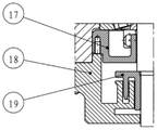
The speed reducer high-speed shaft adopts solitary labyrinth seal system to include: a labyrinth ring I17, a transparent cover I18 and an oil slinger I19; the oil slinger I19 is made of steel materials and is connected to a high-speed shaft of the speed reducer through interference; the transparent cover I18 is an iron casting and is arranged on the speed reducer box body through a bolt group; the labyrinth ring I17 is made of steel materials and is arranged at a bearing inside the speed reducer box body in a clearance fit mode; the transparent cover I18 and the labyrinth ring I17 are stopped through a pin shaft; the labyrinth ring I17, the transparent cover I18 and the oil slinger I19 form a labyrinth sealing structure of the high-speed shaft of the speed reducer, and are used for sealing a circulating lubrication system and a splash lubrication system.
The labyrinth seal system and oil seal combined seal system combination adopted by the upper part and the middle part of the driving axle 32 comprises: the oil seal structure comprises a pressure plate 20, an oil seal I21, a transparent cover II 22, an oil slinger II 23, a labyrinth ring II 24, a labyrinth ring III 25, a labyrinth ring IV 26, an oil slinger III 27 and an oil seal II 28;
the oil slinger II 23 is made of steel materials and is connected to the upper part of the driving axle 32 through interference; the first oil seal 21 is arranged in the second transparent cover 22 and the axial position is limited by the pressure plate 20; the second transparent cover 22 is an iron casting and is arranged on the speed reducer box body through a bolt group; the second labyrinth ring 24 is made of steel materials and is arranged inside the speed reducer box body in a clearance fit mode; the second transparent cover 22 and the second labyrinth ring 24 are stopped through a pin shaft; the pressure plate 20, the oil seal I21, the through cover II 22, the oil slinger II 23 and the labyrinth ring II 24 form a combined sealing structure at the upper part of a driving axle 32, and are used for sealing a circulating lubrication system and a splash lubrication system;
the oil slinger III 27 is made of steel materials and is connected to the middle part of the driving axle 32 through interference; the second oil seal 28 is mounted in the axle box 16; the third labyrinth ring 25 is made of steel material and is arranged in the axle box 16 through clearance fit; the labyrinth ring IV 26 is an iron casting, is arranged in the axle box 16 through interference fit and is stopped through a pin shaft; the third labyrinth ring 25, the fourth labyrinth ring 26, the third oil slinger 27 and the second oil seal 28 form a middle combined sealing structure of the driving axle 32, and are used for sealing a circulating lubrication system and a splash lubrication system.
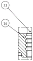
The labyrinth seal system employed in the lower portion of the drive axle 32 includes: the first shaft sleeve 29 and the fifth labyrinth ring 31 are connected to a drive axle 32 in an interference mode; the labyrinth ring five 31 is made of steel materials; the third transparent cover 30 is a cast iron piece and is arranged on the axle box 16 through a bolt group; the axle box 16 is provided with an annular groove to form another sealing structure with the driving axle 32; the first shaft sleeve 29, the third transparent cover 30, the fifth labyrinth ring 31 and the annular groove formed in the axle box 16 form a sealing structure at the lower part of the drive axle 32, and are used for sealing a grease lubrication system.
Finally, it should be noted that: the above embodiments are only used to illustrate the technical solution of the present invention, and not to limit the same; while the invention has been described in detail and with reference to the foregoing embodiments, it will be understood by those skilled in the art that: the technical solutions described in the foregoing embodiments may still be modified, or some or all of the technical features may be equivalently replaced; and the modifications or the substitutions do not make the essence of the corresponding technical solutions depart from the scope of the technical solutions of the embodiments of the present invention.
Claims (10)
1. The utility model provides a big axle load metallurgical vehicle walks lubrication and sealing system of driving speed reducer which characterized in that:
the lubricating and sealing system of the walking driving speed reducer of the large-axle-weight metallurgical vehicle comprises: a lubrication system, a dynamic seal system;
the lubricating system is a structure combining a circulating lubricating system, a splash lubricating system and a grease lubricating system, and is used for solving the problem that the circulating lubricating system cannot be stopped for maintenance when in failure in the operation of a metallurgical vehicle;
the dynamic sealing system is a labyrinth sealing system and oil seal combined sealing system structure and is used for solving the problem that the oil seal cannot be replaced due to narrow bottom space of a metallurgical vehicle.
2. The lubrication and sealing system of a large axle weight metallurgical vehicle running drive speed reducer according to claim 1, wherein:
the circulating lubrication system comprises: the device comprises a throttle pipe (1), a bearing oil nozzle (2), a gear oil nozzle (3), an oil feeding cover plate (4), an oil pump (5), a one-way valve (9) and an oil absorption filter (10);
the oil absorption filter (10) is arranged in an oil return hole at the lower part of the speed reducer box body through a bolt group;
the one-way valve (9) is vertically arranged at the rear end of the oil absorption filter (10) to ensure that lubricating oil cannot flow back;
the fixed part of the oil pump (5) is connected with the speed reducer box body through a bolt group and fixedly arranged on the speed reducer box body, and the rotating part is connected with the high-speed shaft of the speed reducer through a key slot to obtain power;
the input end of the oil pump (5) is connected with an oil absorption filter (10) through a pipeline and a one-way valve (9);
the tail end of one branch of the output end of the oil pump (5) is provided with a throttle pipe (1) and a bearing oil nozzle (2) to lubricate a high-speed shaft bearing of the speed reducer, and a middle shaft of the speed reducer is lubricated through a lubricating hole formed in the box body of the speed reducer;
the tail end of the other branch at the output end of the oil pump (5) is provided with a gear oil nozzle (3) for lubricating a first-stage meshing part of the speed reducer;
the gear oil nozzle (3) is arranged on the oil feeding cover plate (4);
the oil feeding cover plate (4) is arranged on the speed reducer box body;
the oil pump (5) absorbs oil through an oil absorption filter (10) arranged in the speed reducer box body, the oil passes through a one-way valve (9) and a pipeline oil pump (5) and lubricates a high-speed shaft bearing and a middle shaft in the speed reducer through a throttle pipe (1) and a bearing oil nozzle (2) of one branch and lubricates a first-stage meshing part of the speed reducer through a gear oil nozzle (3) of the other branch.
3. The lubrication and sealing system of a large axle weight metallurgical vehicle running drive speed reducer according to claim 2, wherein:
the oil absorption filter (10) is provided with a blockage signal transmitter (8) which monitors the running condition of the circulating lubrication system in real time and feeds the running condition back to a metallurgical vehicle control room.
4. The lubrication and sealing system of a large axle weight metallurgical vehicle running drive speed reducer according to claim 2, wherein:
the speed reducer box body is provided with a protective frame (7) for preventing impurities in the rail environment from damaging the oil absorption filter (10) and the blocking signal transmitter (8).
5. The lubrication and sealing system of a large axle weight metallurgical vehicle running drive speed reducer according to claim 1, wherein:
the splash lubrication system controls the accurate lubricating oil level through a liquid level meter (6) fixedly arranged in the speed reducer box body, performs standby lubrication on the first-stage meshing part of the speed reducer, fully lubricates the second-stage meshing part of the speed reducer and a middle bearing of an axle box (16), and solves the problem that the required oil level is higher due to the structural reason of a traveling driving speed reducer of a large-axle-weight self-propelled metallurgical vehicle;
the splash lubrication system collects splashed lubricating oil through a plug screw (12), an oil receiving box I (13), an oil receiving box II (14) and a lubricating groove arranged on the speed reducer box body to perform standby lubrication on bearings of a high-speed shaft and a middle shaft of the speed reducer, so that the purpose of immediately stopping and maintaining the circulating lubrication system when the circulating lubrication system fails is achieved, and meanwhile, parts such as the box body and the like are provided with a plurality of lubricating holes and grooves to enhance the lubricating sufficiency.
6. The lubrication and sealing system of a large axle weight metallurgical vehicle running drive speed reducer according to claim 1, wherein:
the grease lubrication system injects grease into a lower bearing of the axle box (16) through an oil cup (15) arranged at the lower part of the axle box (16), so that the purpose of grease lubrication is achieved.
7. The lubrication and sealing system of a large axle weight metallurgical vehicle running drive speed reducer according to claim 1, wherein:
the labyrinth seal system and the oil seal combined seal system of the dynamic seal system adopt an independent form and a combined form to seal a high-speed shaft of a speed reducer and a driving axle (32);
the high-speed shaft of the speed reducer adopts a single labyrinth seal system mode to seal a circulating lubrication system and a splash lubrication system;
the upper part and the middle part of the driving axle (32) adopt a combined mode of a labyrinth seal system and an oil seal combined seal system to seal a circulating lubrication system and a splash lubrication system;
the lower part of the driving axle (32) adopts a single labyrinth seal system mode to seal a grease lubrication system.
8. The lubrication and sealing system of a large axle weight metallurgical vehicle running drive speed reducer according to claim 7, wherein:
the speed reducer high-speed shaft adopts an independent labyrinth seal system and comprises: a first labyrinth ring (17), a first transparent cover (18) and a first oil slinger (19);
the oil slinger I (19) is made of steel materials and is connected to a high-speed shaft of the speed reducer through interference;
the first transparent cover (18) is an iron casting and is arranged on the speed reducer box body through a bolt group;
the labyrinth ring I (17) is made of steel materials and is arranged at a bearing in the speed reducer box body in a clearance fit mode;
the transparent cover I (18) and the labyrinth ring I (17) are stopped through a pin shaft;
the labyrinth ring I (17), the transparent cover I (18) and the oil slinger I (19) form a labyrinth seal structure of the high-speed shaft of the speed reducer, and are used for sealing a circulating lubrication system and a splash lubrication system.
9. The lubrication and sealing system of a large axle weight metallurgical vehicle running drive speed reducer according to claim 7, wherein:
the labyrinth seal system and the oil seal combined seal system combination adopted at the upper part and the middle part of the driving axle (32) comprise: the oil seal structure comprises a pressure plate (20), a first oil seal (21), a second transparent cover (22), a second oil slinger (23), a second labyrinth ring (24), a third labyrinth ring (25), a fourth labyrinth ring (26), a third oil slinger (27) and a second oil seal (28);
the oil slinger II (23) is made of steel materials and is connected to the upper part of the driving axle (32) through interference;
the first oil seal (21) is arranged in the second transparent cover (22) and the axial position is limited by the pressure plate (20);
the second transparent cover (22) is an iron casting and is arranged on the speed reducer box body through a bolt group;
the second labyrinth ring (24) is made of steel materials and is arranged in the speed reducer box body in a clearance fit mode;
the transparent cover II (22) and the labyrinth ring II (24) are stopped through a pin shaft;
the pressure plate (20), the first oil seal (21), the second transparent cover (22), the second oil slinger (23) and the second labyrinth ring (24) form a combined sealing structure at the upper part of a driving axle (32) and are used for sealing a circulating lubrication system and a splash lubrication system;
the oil slinger III (27) is made of steel materials and is connected to the middle part of the driving axle (32) through interference;
the second oil seal (28) is arranged in the axle box (16);
the third labyrinth ring (25) is made of steel materials and is arranged in the axle box (16) through clearance fit;
the fourth labyrinth ring (26) is an iron casting, is arranged in the axle box (16) in an interference fit manner and is stopped by a pin shaft;
and the third labyrinth ring (25), the fourth labyrinth ring (26), the third oil slinger (27) and the second oil seal (28) form a middle combined sealing structure of a driving axle (32) and are used for sealing a circulating lubrication system and a splash lubrication system.
10. The lubrication and sealing system of a large axle weight metallurgical vehicle running drive speed reducer according to claim 7, wherein:
the labyrinth seal system adopted at the lower part of the driving axle (32) comprises:
the first shaft sleeve (29) and the fifth labyrinth ring (31) are connected to a driving axle (32) in an interference manner;
the labyrinth ring V (31) is made of steel material;
the third transparent cover (30) is an iron casting and is arranged on the axle box (16) through a bolt group;
the axle box (16) is provided with an annular groove to form another sealing structure with the driving axle (32);
the first shaft sleeve (29), the third transparent cover (30), the fifth labyrinth ring (31) and the annular groove formed in the shaft box (16) form a sealing structure at the lower part of a driving axle (32) and are used for sealing a grease lubricating system.
Priority Applications (1)
| Application Number | Priority Date | Filing Date | Title |
|---|---|---|---|
| CN202210108665.9A CN114439911B (en) | 2022-01-28 | 2022-01-28 | Lubrication and sealing system of travelling drive speed reducer of large-axle-weight metallurgical vehicle |
Applications Claiming Priority (1)
| Application Number | Priority Date | Filing Date | Title |
|---|---|---|---|
| CN202210108665.9A CN114439911B (en) | 2022-01-28 | 2022-01-28 | Lubrication and sealing system of travelling drive speed reducer of large-axle-weight metallurgical vehicle |
Publications (2)
| Publication Number | Publication Date |
|---|---|
| CN114439911A true CN114439911A (en) | 2022-05-06 |
| CN114439911B CN114439911B (en) | 2023-09-26 |
Family
ID=81371749
Family Applications (1)
| Application Number | Title | Priority Date | Filing Date |
|---|---|---|---|
| CN202210108665.9A Active CN114439911B (en) | 2022-01-28 | 2022-01-28 | Lubrication and sealing system of travelling drive speed reducer of large-axle-weight metallurgical vehicle |
Country Status (1)
| Country | Link |
|---|---|
| CN (1) | CN114439911B (en) |
Families Citing this family (1)
| Publication number | Priority date | Publication date | Assignee | Title |
|---|---|---|---|---|
| DE102020204204A1 (en) * | 2020-03-31 | 2021-09-30 | Zf Friedrichshafen Ag | Input shaft seals for a gearbox series |
Citations (16)
| Publication number | Priority date | Publication date | Assignee | Title |
|---|---|---|---|---|
| JP2003032946A (en) * | 2001-07-18 | 2003-01-31 | Toshiba Transport Eng Inc | Structure of oil lubrication bearing for vehicle motor |
| CN101832385A (en) * | 2010-04-29 | 2010-09-15 | 胡炜 | Lower output shaft seal device of vertical reducer and reducer with same |
| CN103162012A (en) * | 2011-12-12 | 2013-06-19 | 上海市基础工程有限公司 | Machine head drive and sealing device of slurry balance tube push bench |
| CN104033576A (en) * | 2014-06-18 | 2014-09-10 | 江苏赫夫特齿轮制造有限公司 | Vertical reducer seal structure and vertical reducer |
| CN104214278A (en) * | 2014-08-28 | 2014-12-17 | 郑州机械研究所 | Lubricated type primary speed reducing structure for vertical speed reducer, and vertical speed reducer |
| CN105003640A (en) * | 2015-07-30 | 2015-10-28 | 宁波东力齿轮箱有限公司 | Lubricating and sealing structure of speed reducer input shaft |
| JP2017009085A (en) * | 2015-06-25 | 2017-01-12 | 新日鐵住金株式会社 | Non-contact type seal device at railway vehicle gear device |
| CN206694411U (en) * | 2017-04-27 | 2017-12-01 | 大连交通大学 | Electric shovel pushing decelerator exports main shaft sliding bearing low pressure oil lubrication system |
| CN109027196A (en) * | 2018-10-08 | 2018-12-18 | 大连华锐重工集团股份有限公司 | Half-direct-driven wind generation main transmission gearbox built in a kind of main shaft |
| CN209705249U (en) * | 2018-12-14 | 2019-11-29 | 南京德伦重载齿轮箱有限公司 | A kind of rolling bearing high-speed gear box |
| EP3657645A1 (en) * | 2018-11-26 | 2020-05-27 | ZF Drivetech (Suzhou) Co., Ltd. | Integrated central drive system |
| CN211146049U (en) * | 2019-08-30 | 2020-07-31 | 厦门朴思起重设备有限公司 | Automatic grease double-channel lubricating device for wheel or pulley bearing |
| CN211975779U (en) * | 2020-03-31 | 2020-11-20 | 沈阳乾鼎机械制造有限公司 | Gear reducer for material piling and taking walking |
| CN111997635A (en) * | 2020-08-24 | 2020-11-27 | 中铁工程装备集团有限公司 | Labyrinth backpressure structure of shield tunneling machine, sealing system and working method of sealing system |
| CN112389486A (en) * | 2020-12-25 | 2021-02-23 | 中车戚墅堰机车有限公司 | Lubricating and sealing structure of wheel shaft driving system |
| CN217381554U (en) * | 2022-01-28 | 2022-09-06 | 大连华锐重工集团股份有限公司 | Lubricating and sealing system of traveling driving speed reducer of large-axle-weight metallurgical vehicle |
-
2022
- 2022-01-28 CN CN202210108665.9A patent/CN114439911B/en active Active
Patent Citations (16)
| Publication number | Priority date | Publication date | Assignee | Title |
|---|---|---|---|---|
| JP2003032946A (en) * | 2001-07-18 | 2003-01-31 | Toshiba Transport Eng Inc | Structure of oil lubrication bearing for vehicle motor |
| CN101832385A (en) * | 2010-04-29 | 2010-09-15 | 胡炜 | Lower output shaft seal device of vertical reducer and reducer with same |
| CN103162012A (en) * | 2011-12-12 | 2013-06-19 | 上海市基础工程有限公司 | Machine head drive and sealing device of slurry balance tube push bench |
| CN104033576A (en) * | 2014-06-18 | 2014-09-10 | 江苏赫夫特齿轮制造有限公司 | Vertical reducer seal structure and vertical reducer |
| CN104214278A (en) * | 2014-08-28 | 2014-12-17 | 郑州机械研究所 | Lubricated type primary speed reducing structure for vertical speed reducer, and vertical speed reducer |
| JP2017009085A (en) * | 2015-06-25 | 2017-01-12 | 新日鐵住金株式会社 | Non-contact type seal device at railway vehicle gear device |
| CN105003640A (en) * | 2015-07-30 | 2015-10-28 | 宁波东力齿轮箱有限公司 | Lubricating and sealing structure of speed reducer input shaft |
| CN206694411U (en) * | 2017-04-27 | 2017-12-01 | 大连交通大学 | Electric shovel pushing decelerator exports main shaft sliding bearing low pressure oil lubrication system |
| CN109027196A (en) * | 2018-10-08 | 2018-12-18 | 大连华锐重工集团股份有限公司 | Half-direct-driven wind generation main transmission gearbox built in a kind of main shaft |
| EP3657645A1 (en) * | 2018-11-26 | 2020-05-27 | ZF Drivetech (Suzhou) Co., Ltd. | Integrated central drive system |
| CN209705249U (en) * | 2018-12-14 | 2019-11-29 | 南京德伦重载齿轮箱有限公司 | A kind of rolling bearing high-speed gear box |
| CN211146049U (en) * | 2019-08-30 | 2020-07-31 | 厦门朴思起重设备有限公司 | Automatic grease double-channel lubricating device for wheel or pulley bearing |
| CN211975779U (en) * | 2020-03-31 | 2020-11-20 | 沈阳乾鼎机械制造有限公司 | Gear reducer for material piling and taking walking |
| CN111997635A (en) * | 2020-08-24 | 2020-11-27 | 中铁工程装备集团有限公司 | Labyrinth backpressure structure of shield tunneling machine, sealing system and working method of sealing system |
| CN112389486A (en) * | 2020-12-25 | 2021-02-23 | 中车戚墅堰机车有限公司 | Lubricating and sealing structure of wheel shaft driving system |
| CN217381554U (en) * | 2022-01-28 | 2022-09-06 | 大连华锐重工集团股份有限公司 | Lubricating and sealing system of traveling driving speed reducer of large-axle-weight metallurgical vehicle |
Non-Patent Citations (2)
| Title |
|---|
| 徐从保: "迷宫式离心密封", 润滑与密封, no. 05 * |
| 薛群山: "减速器轴端动密封结构改进", 矿山机械, no. 08 * |
Also Published As
| Publication number | Publication date |
|---|---|
| CN114439911B (en) | 2023-09-26 |
Similar Documents
| Publication | Publication Date | Title |
|---|---|---|
| US8960362B2 (en) | Lubrication arrangement for a drive axle of a haul vehicle | |
| CN100485226C (en) | Improved lubrication in a transmission | |
| US5197929A (en) | Drive shaft | |
| CN104002954B (en) | Vessel tail shaft device | |
| CN217381554U (en) | Lubricating and sealing system of traveling driving speed reducer of large-axle-weight metallurgical vehicle | |
| CN101552514B (en) | High-rotating-speed pulling motor | |
| US9309961B2 (en) | Axle assembly | |
| CN114439911A (en) | Lubricating and sealing system of traveling driving speed reducer of large-axle-weight metallurgical vehicle | |
| CN107588315B (en) | Hub bearing thin oil lubrication, circulation, cooling and filtering device for mining vehicle | |
| CN216886647U (en) | Axle-holding walking driving speed reducer of large axle load self-propelled metallurgical vehicle | |
| JPH074590A (en) | Lubricant re-stabilizer for gearing | |
| CN205371580U (en) | Hydraulic driving axle gear box | |
| CN104500700B (en) | Streetcar gear transmission device | |
| CN110285212A (en) | A kind of circulation oil jet lubrication vertical speed reducer | |
| CN204284310U (en) | Angle transmission, power transmission system and monomotor hoist | |
| CN111720552A (en) | Rear drive axle input end sealing structure and mining dump truck | |
| CN104373509A (en) | Angle drive device, power drive system and a single-engine hoist | |
| CN207328472U (en) | A kind of horizontal wheels of circulating oil lubrication and there is its bogie and monorail train | |
| CN102963212B (en) | Vehicle and rigid dead axle | |
| CN114435412A (en) | Axle-holding walking driving speed reducer of large axle load self-propelled metallurgical vehicle | |
| CN102431401A (en) | Lubricating and sealing device for full-hanging traction hook | |
| CN103016537A (en) | Oil-circulating type MC (Monomer Casting) nylon pulley | |
| CN207514552U (en) | Mine car hub bearing thin oil lubricant circulating cooling filter device | |
| CN107379892A (en) | Drive axle hub and automobile | |
| CN107504137B (en) | Grease separation lubricated wheel reduction gear |
Legal Events
| Date | Code | Title | Description |
|---|---|---|---|
| PB01 | Publication | ||
| PB01 | Publication | ||
| SE01 | Entry into force of request for substantive examination | ||
| SE01 | Entry into force of request for substantive examination | ||
| GR01 | Patent grant | ||
| GR01 | Patent grant |