CN114412101A - Spliced grid plate and mounting method thereof - Google Patents
Spliced grid plate and mounting method thereof Download PDFInfo
- Publication number
- CN114412101A CN114412101A CN202210047077.9A CN202210047077A CN114412101A CN 114412101 A CN114412101 A CN 114412101A CN 202210047077 A CN202210047077 A CN 202210047077A CN 114412101 A CN114412101 A CN 114412101A
- Authority
- CN
- China
- Prior art keywords
- grid
- bottom plate
- wall panel
- spliced
- grating
- Prior art date
- Legal status (The legal status is an assumption and is not a legal conclusion. Google has not performed a legal analysis and makes no representation as to the accuracy of the status listed.)
- Pending
Links
- 238000000034 method Methods 0.000 title claims abstract description 13
- 239000010410 layer Substances 0.000 claims description 14
- 238000003780 insertion Methods 0.000 claims description 8
- 230000037431 insertion Effects 0.000 claims description 8
- 238000007789 sealing Methods 0.000 claims description 4
- 230000008878 coupling Effects 0.000 claims description 3
- 238000010168 coupling process Methods 0.000 claims description 3
- 238000005859 coupling reaction Methods 0.000 claims description 3
- 239000012790 adhesive layer Substances 0.000 claims description 2
- 238000005452 bending Methods 0.000 claims 1
- 239000012858 resilient material Substances 0.000 claims 1
- 238000009434 installation Methods 0.000 abstract description 14
- 230000003014 reinforcing effect Effects 0.000 description 4
- 238000005728 strengthening Methods 0.000 description 4
- 239000002344 surface layer Substances 0.000 description 4
- 238000005034 decoration Methods 0.000 description 3
- 239000013013 elastic material Substances 0.000 description 3
- 230000000712 assembly Effects 0.000 description 2
- 238000000429 assembly Methods 0.000 description 2
- 210000001503 joint Anatomy 0.000 description 2
- 238000010030 laminating Methods 0.000 description 2
- 230000011218 segmentation Effects 0.000 description 2
- 238000005267 amalgamation Methods 0.000 description 1
- 230000009286 beneficial effect Effects 0.000 description 1
- 230000000903 blocking effect Effects 0.000 description 1
- 238000010276 construction Methods 0.000 description 1
- 230000000694 effects Effects 0.000 description 1
- 239000013536 elastomeric material Substances 0.000 description 1
- 230000002349 favourable effect Effects 0.000 description 1
- 230000002045 lasting effect Effects 0.000 description 1
- 239000000463 material Substances 0.000 description 1
- 210000003205 muscle Anatomy 0.000 description 1
- 238000005215 recombination Methods 0.000 description 1
- 230000006798 recombination Effects 0.000 description 1
- 230000002787 reinforcement Effects 0.000 description 1
- 238000000926 separation method Methods 0.000 description 1
- 238000006467 substitution reaction Methods 0.000 description 1
Images
Classifications
-
- E—FIXED CONSTRUCTIONS
- E04—BUILDING
- E04F—FINISHING WORK ON BUILDINGS, e.g. STAIRS, FLOORS
- E04F13/00—Coverings or linings, e.g. for walls or ceilings
- E04F13/07—Coverings or linings, e.g. for walls or ceilings composed of covering or lining elements; Sub-structures therefor; Fastening means therefor
- E04F13/08—Coverings or linings, e.g. for walls or ceilings composed of covering or lining elements; Sub-structures therefor; Fastening means therefor composed of a plurality of similar covering or lining elements
- E04F13/0801—Separate fastening elements
- E04F13/0832—Separate fastening elements without load-supporting elongated furring elements between wall and covering elements
- E04F13/0833—Separate fastening elements without load-supporting elongated furring elements between wall and covering elements not adjustable
- E04F13/0835—Separate fastening elements without load-supporting elongated furring elements between wall and covering elements not adjustable the fastening elements extending into the back side of the covering elements
- E04F13/0837—Separate fastening elements without load-supporting elongated furring elements between wall and covering elements not adjustable the fastening elements extending into the back side of the covering elements extending completely through the covering elements
-
- E—FIXED CONSTRUCTIONS
- E04—BUILDING
- E04F—FINISHING WORK ON BUILDINGS, e.g. STAIRS, FLOORS
- E04F13/00—Coverings or linings, e.g. for walls or ceilings
- E04F13/07—Coverings or linings, e.g. for walls or ceilings composed of covering or lining elements; Sub-structures therefor; Fastening means therefor
- E04F13/08—Coverings or linings, e.g. for walls or ceilings composed of covering or lining elements; Sub-structures therefor; Fastening means therefor composed of a plurality of similar covering or lining elements
- E04F13/0885—Coverings or linings, e.g. for walls or ceilings composed of covering or lining elements; Sub-structures therefor; Fastening means therefor composed of a plurality of similar covering or lining elements specially adapted for being adhesively fixed to the wall; Fastening means therefor; Fixing by means of plastics materials hardening after application
-
- E—FIXED CONSTRUCTIONS
- E04—BUILDING
- E04F—FINISHING WORK ON BUILDINGS, e.g. STAIRS, FLOORS
- E04F13/00—Coverings or linings, e.g. for walls or ceilings
- E04F13/07—Coverings or linings, e.g. for walls or ceilings composed of covering or lining elements; Sub-structures therefor; Fastening means therefor
- E04F13/08—Coverings or linings, e.g. for walls or ceilings composed of covering or lining elements; Sub-structures therefor; Fastening means therefor composed of a plurality of similar covering or lining elements
- E04F13/0889—Coverings or linings, e.g. for walls or ceilings composed of covering or lining elements; Sub-structures therefor; Fastening means therefor composed of a plurality of similar covering or lining elements characterised by the joints between neighbouring elements, e.g. with joint fillings or with tongue and groove connections
- E04F13/0894—Coverings or linings, e.g. for walls or ceilings composed of covering or lining elements; Sub-structures therefor; Fastening means therefor composed of a plurality of similar covering or lining elements characterised by the joints between neighbouring elements, e.g. with joint fillings or with tongue and groove connections with tongue and groove connections
-
- E—FIXED CONSTRUCTIONS
- E04—BUILDING
- E04F—FINISHING WORK ON BUILDINGS, e.g. STAIRS, FLOORS
- E04F2201/00—Joining sheets or plates or panels
- E04F2201/02—Non-undercut connections, e.g. tongue and groove connections
- E04F2201/023—Non-undercut connections, e.g. tongue and groove connections with a continuous tongue or groove
-
- E—FIXED CONSTRUCTIONS
- E04—BUILDING
- E04F—FINISHING WORK ON BUILDINGS, e.g. STAIRS, FLOORS
- E04F2201/00—Joining sheets or plates or panels
- E04F2201/04—Other details of tongues or grooves
- E04F2201/043—Other details of tongues or grooves with tongues and grooves being formed by projecting or recessed parts of the panel layers
Landscapes
- Engineering & Computer Science (AREA)
- Architecture (AREA)
- Civil Engineering (AREA)
- Structural Engineering (AREA)
- Finishing Walls (AREA)
Abstract
The invention discloses a splicing type grating plate and an installation method thereof, comprising a first grating component, a second grating component and a third grating component which are sequentially spliced end to end and are attached to a wall panel, wherein the first grating component comprises a grating unit and a limiting part arranged at the end part of the grating unit, the second grating component comprises a grating unit, a limiting part arranged at one end of the grating unit and a plug connector arranged at the other end of the grating unit, the third grating component comprises a grating unit and a plug connector arranged at the end part of the grating unit, the limiting part comprises a bottom plate attached to the wall panel and an L-shaped bent hook vertically fixedly connected with the bottom plate, the bottom plate and the L-shaped bent hook enclose to form a horizontal limiting groove, the plug connector comprises a rectangular block and a splicing strip fixedly connected with the rectangular block, when the end part of the bottom plate is abutted against the rectangular block, the splicing strip is spliced in the horizontal limiting groove, the bottom plate is fixedly connected with the wall panel through a screw, can be followed the front and consolidated when being connected with the shingle nail, the installation is firm and efficient.
Description
Technical Field
The invention relates to the field of wall decoration, in particular to a spliced grid plate and an installation method thereof.
Background
The background wall is a home decoration art decorated on a television in a family living room, a sofa, a vestibule, a bedroom wall and the like, has various styles, meets the decoration requirements of consumers by using a novel conception and an advanced process, and reflects the quality of the art, so that the background wall becomes a perfect combination of business and art.
In the prior art, chinese patent publication No. CN213837479U discloses a novel splicing structure for retaining wall and background wall grids, which comprises a first splicing grid plate, a second splicing grid plate, a limiting protection plate and a reinforcing rib, wherein the second splicing grid plate is clamped at two sides of the first splicing grid plate, the reinforcing rib is inserted into the first splicing grid plate and the second splicing grid plate to reinforce the connection between the first splicing grid plate and the second splicing grid plate, the limiting protection plate is clamped at one side of the second splicing grid plate away from the first splicing grid plate to limit the second splicing grid plate and the reinforcing rib, the second splicing grid plate is fixed at two sides of the first splicing grid plate when in use, the second grid strip is inserted into the first clamping groove, the first splicing grid plate and the second splicing grid plate are connected by clamping, and then another second splicing grid plate is placed at one side of the second splicing grid plate away from the first splicing grid plate, let the first card strip of a second concatenation grid board get into inside the first draw-in groove of another second concatenation grid board, let two second concatenation grid boards pass through the joint and connect, thereby be in the same place a plurality of second concatenation grid boards and the concatenation of first concatenation grid board, then insert the strengthening rib inside the muscle groove of wearing of first concatenation grid board and second concatenation grid board, be used for strengthening the connection of first concatenation grid board and second concatenation grid board, above-mentioned scheme is through the cooperation of each accessory, the process of installation can be very big simplification, thereby accelerate the efficiency of construction, and consolidate the connection of first concatenation grid board and second concatenation grid board with the mode that sets up the strengthening rib, the stability of device has been promoted.
However, the above scheme has several problems: 1. when the grid is connected with the wall panel after being assembled, in order to not damage the grid surface layer structure, the screw needs to be reinforced from the back of the wall panel, so that the grid and the wall panel need to be assembled firstly and then installed on the wall, the volume of the wall panel is large, the installation mode has long processing period and low overall installation efficiency; 2. this grid structure passes through the strengthening rib fixed, and the form that finally presents is a holistic panel, when being connected with shingle nail, if meet adjacent shingle nail because the error when the complete horizontally state, this grid structure can not all laminate in all panels, and the fixed mode of recombination screw then can appear that partial position screw in degree of depth is shallow and lead to connecting insecure phenomenon.
Disclosure of Invention
In order to solve the problems, the invention provides the splicing type grid plate and the installation method thereof, when the splicing type grid plate is connected with a wall panel, the splicing type grid plate can be reinforced from the front, and the splicing type grid plate is firm in installation and high in efficiency.
The technical scheme of the invention is that a spliced grid plate is provided and used as a covering layer of a wall panel, the spliced grid plate comprises a first grid assembly, a second grid assembly and a third grid assembly which are sequentially spliced end to end and are attached to the wall panel, the first grid assembly comprises a grid unit and a limiting piece arranged at the end part of the grid unit, the second grid assembly comprises a grid unit, a limiting piece arranged at one end of the grid unit and a plug connector arranged at the other end of the grid unit, the third grid assembly comprises a grid unit and a plug connector arranged at the end part of the grid unit, the limiting piece comprises a bottom plate attached to the wall panel and an L-shaped bent hook vertically fixedly connected with the bottom plate, the bottom plate and the L-shaped bent hook enclose a horizontal limiting groove, and the plug connector comprises a rectangular block and a splicing strip fixedly connected with the rectangular block, when the end part of the bottom plate is abutted against the rectangular block, the inserting strips are inserted into the horizontal limiting grooves, and the bottom plate is fixedly connected with the wall panel through screws.
Preferably, the middle part of the bottom plate is provided with a first protrusion, the insertion strip is provided with a second protrusion opposite to the first protrusion, and when the insertion strip is inserted into the horizontal limiting groove, the first protrusion and the second protrusion are attached to form a sealing strip and enclose the side surfaces of the bottom plate and the rectangular block to form a containing cavity.
Preferably, the grid unit is a background plate provided with a plurality of U-shaped grooves, the rectangular block is provided with an arc-shaped groove, and the inserting strips are fixedly connected with the end parts of the arc-shaped groove.
Preferably, the bottom of the grid unit is provided with an adhesive layer.
Preferably, the top of the inserting strip is provided with an elastic material layer.
Preferably, the grid unit and the limiting part are integrally formed, and the grid unit and the plug connector are integrally formed.
Preferably, the number of the second grid assemblies is at least 1.
Preferably, the number of the U-shaped grooves is 3-5, and the width of the notches of the U-shaped grooves is 10-12 mm.
Further, a mounting method of the spliced grid plate is also provided, and the mounting method comprises the following steps:
s1, sequentially mounting wall panels on a wall surface base layer;
s2, attaching a first grid assembly to the wall panel, and fixing a bottom plate of the first grid assembly and the wall panel through screws;
s3, inserting the inserting strips of the second grid assembly into the horizontal limiting grooves of the limiting parts of the first grid assembly, and fixing the floor of the second grid assembly and the wall panel by using screws at the other end of the second grid assembly;
and S4, inserting the inserting strips of the third grid assembly into the horizontal limiting grooves of the limiting parts of the second grid assembly, and bonding the bottom of the third grid assembly with the wall panel.
Preferably, step S2 further includes bonding the bottom of the first grid assembly to the wall panel.
The invention has the beneficial effects that:
1. the first grid assembly, the second grid assembly and the third grid assembly are connected end to end, the inserting strips are horizontally inserted into the horizontal limiting grooves, the inserting strips cover the bottom plate, the wall panel does not need to be installed from the back of the wall panel in a reinforcing mode in order to protect the surface layer structure of the grids, the installation sequence of the wall panel and the grids is not limited, and the installation efficiency is improved;
2. the connection of the grating plates and the wall panel is segmented, and the angle between the grating plate assemblies has an adjustment range, so that when the adjacent wall panels are not completely parallel after being butted, the grating plates and the wall panel are attached in a segmented manner, the situation that the grating plates and the wall panel are partially separated is avoided, and the installation is firm;
3. in this scheme, after adjacent grid subassembly is inserted each other and is closed, first arch, the protruding laminating of second constitute and seal the strip, and with the side of bottom plate, rectangular block encloses to close and forms the holding chamber, and for the mode of direct fluting on the bottom plate, the thickness of bottom plate is not reduced to this kind of structure, has guaranteed grid structure's joint strength, and no matter the screw in degree of depth of screw is dark or not simultaneously, the relative position of bottom plate and grafting strip is unchangeable, prevents to occupy spacing inslot space because the protrusion of screw top is too much, hinders the grafting strip to insert the spacing inslot.
Drawings
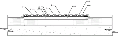
FIG. 1 is a schematic view of a mounting structure of a spliced grid plate in the scheme;
FIG. 2 is a schematic view of a connection structure of a stopper and a plug connector;
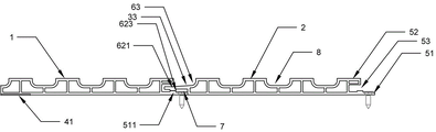
in the figure: 1. a first grid assembly; 2. a second grid assembly; 3. a third grid assembly; 4. a grill unit; 5. a limiting member; 6. a plug-in unit; 51. a base plate; 52. an L-shaped bent hook; 53. a limiting groove; 61. a rectangular block; 62. inserting strips; 511. a first protrusion; 621. a second protrusion; 623. a closure strip; 7. an accommodating cavity; 8. a U-shaped groove; 9. a background plate; 63. an arc-shaped slot; 41. a bonding layer; 33. a layer of elastomeric material.
Detailed Description
The present invention will be described in further detail with reference to examples.
The description of "first", "second", etc. referred to in the embodiments of the present invention is for descriptive purposes only and is not to be construed as indicating or implying any relative importance or implicit indication of the number of technical features indicated, whereby the features defined as "first", "second", etc. may explicitly or implicitly include at least one such feature.
Meanwhile, the terms "upper", "lower", "front", "rear", "left", "right", "inner", "outer", etc., indicate orientations or positional relationships based on those shown in the drawings, and are only for convenience of describing the present invention and simplifying the description, but do not indicate or imply that the referred device or element must have a specific orientation, be constructed in a specific orientation, and be operated, and thus, should not be construed as limiting the present invention.
In the description of the present invention, it is to be noted that, unless otherwise explicitly specified or limited, the terms "mounted", "connected", "abutting" and "scarf joint" are to be understood broadly, and may be, for example, fixedly connected, detachably connected, or integrally connected; can be mechanically or electrically connected; they may be connected directly or indirectly through intervening media, so to speak, as communicating between the two elements. The specific meaning of the above terms in the present invention can be understood according to specific situations by those skilled in the art.
In order to more clearly understand the technical features, objects and effects of the present invention, embodiments of the present invention will now be described in detail with reference to the accompanying drawings, but the embodiments of the present invention are not limited thereto.
Example 1
A splicing type grating plate is used as a covering layer of a wall panel, and comprises a first grating component 1, a second grating component 2 and a third grating component 3 which are sequentially spliced end to end and are arranged on the wall panel in a pasting mode, wherein the first grating component 1 comprises a grating unit 4 and a limiting part 5 arranged at the end part of the grating unit 4, concretely, in the embodiment, the limiting part 5 is arranged at the right side of the grating unit 4, the second grating component 2 comprises a grating unit 4, a limiting part 5 arranged at one end of the grating unit 4 and a plug connector 6 arranged at the other end of the grating unit 4, concretely, in the embodiment, the limiting part 5 is arranged at the right side of the grating unit 4, the plug connector 6 is arranged at the left side of the grating unit 4, and the third grating component 3 comprises a grating unit 4 and a plug connector 6 arranged at the end part of the grating unit 4, specifically, in this embodiment, the plug connector 6 is disposed on the left side of the grid unit 4, the limiting member 5 includes a bottom plate 51 attached to the wall panel and an L-shaped bent hook 52 vertically and fixedly connected to the bottom plate 51, the bottom plate 51 and the L-shaped bent hook 52 enclose a horizontal limiting groove 53, the plug connector 6 includes a rectangular block 61 and a plug strip 62 fixedly connected to the rectangular block 61, the plug strip 62 is fixedly connected to the middle of the outer side surface of the rectangular block 61, the outer side surface is relative to the connection surface of the rectangular block 61 and the grid unit 4, when the end of the bottom plate 51 abuts against the rectangular block 61, the outer side surface actually abuts against the outer side surface of the rectangular block 61, the plug strip 62 is inserted into the horizontal limiting groove 53, and the bottom plate 51 is fixedly connected to the wall panel through a screw;
when the first grid component 1, the second grid component 2 and the third grid component 3 are connected end to end, the inserting strips 62 are horizontally inserted into the horizontal limiting grooves 53, and the limiting grooves 53 are formed by enclosing the bottom plate 51 and the L-shaped bent hooks 52, so that the inserting strips 62 are positioned on the floor, and the inserting strips 62 cover the bottom plate 51, so that screws can be arranged on the surface layer of the bottom plate 51 and are fixedly connected with the wall panel without influencing the surface layer structure of the whole grid plate, the reinforcement from the back of the wall panel is not needed, the mounting sequence of the wall panel and the grids is not limited during actual mounting, and the mounting efficiency is improved;
in addition, the problem that the adjacent wall panels are not completely parallel and therefore the connection with the grating is not fastened can be solved, and the reason is as follows: first grid subassembly 1 in this scheme, second grid subassembly 2, third grid subassembly 3 all are equipped with bottom plate 51 that can be connected with the shingle nail, and utilize the screw by bottom plate 51's surface course is to shingle nail through connection, the connected mode fastening, need not use prior art with all grid subassembly amalgamations after unified again be connected with the shingle nail, for prior art, the grid board of this scheme is connected with the shingle nail segmentation, angle between the grid board subassembly has the scope of adjustment, consequently when the condition that appears not parallel totally after the butt joint of adjacent shingle nail, grid board and shingle nail segmentation laminating, the situation of grid board and shingle nail part separation can not appear, the installation is firm.
The middle part of the bottom plate 51 is provided with a first protrusion 511, the inserting strip 62 is provided with a second protrusion 621 opposite to the first protrusion 511, when the inserting strip 62 is inserted into the horizontal limiting groove 53, the first protrusion 511 and the second protrusion 621 are attached to form a sealing strip 623, and the sealing strip 623 is enclosed with the side surfaces of the bottom plate 51 and the rectangular block 61 to form an accommodating cavity 7, the top part protrudes out of the bottom plate 51 after the screws are fastened, the accommodating cavity 7 is used for accommodating the top part of the screws, compared with the way of directly slotting on the bottom plate 51, the structure does not reduce the thickness of the bottom plate 51, ensures the connection strength of the grid structure, and simultaneously, no matter whether the screwing depth of the screws is shallow or not, because the first protrusion 511 and the second protrusion 621 are attached, the relative position of the bottom plate 51 and the inserting strip 62 is unchanged, ensures the smoothness of the grid, and prevents the top part of the screws from protruding too much to occupy the inner space of the limiting groove 53, the blocking insertion strip 62 is inserted into the limiting groove 53.
Grid unit 4 is for being equipped with the background board 9 of a plurality of U-shaped grooves 8, rectangular block 61 is equipped with arc wall 63, grafting strip 62 with the tip rigid coupling of arc wall 63, the seting up of U-shaped groove 8 and arc wall 63 are favorable to alleviateing the whole quality of grid, reduce shingle nail's load for the fastness is more lasting after grid and the shingle nail installation.
The bottom of the grid unit 4 is provided with the bonding layer 41, and the bonding connection mode is provided except for screw connection, so that double guarantee is provided for connection of the grid and the wall panel, and the connection is more firm.
The top of the insertion strip 62 is provided with an elastic material layer 33, and the elastic material layer 33 can increase the thickness of the insertion strip 62 to adapt to the grid units 4 with different heights, and meanwhile, the insertion strip is made of a non-rigid material, so that the angle adjustment between the adjacent grid units 4 is not influenced.
The grid unit 4 with locating part 5 integrated into one piece, grid unit 4 with plug connector 6 integrated into one piece makes grid intensity higher.
The number of the second grating elements 2 is at least 1, and when the area of the wall panel is too large, the area of the grating can be expanded through the second grating elements 2.
The number of the U-shaped grooves is 3-5, the width of the groove opening of each U-shaped groove is 10-12mm, and the excessive width of each U-shaped groove 8 is too large, so that the area of each grid unit 4 is larger, and the grid unit is not suitable for installation of non-parallel adjacent wall panels.
Example 2
A mounting method of a splicing type grating plate comprises the following steps:
s1, sequentially mounting wall panels on a wall surface base layer;
s2, attaching the first grid assembly 1 to the wall panel, and fixing a bottom plate 51 of the first grid assembly 1 and the wall panel by using screws;
s3, inserting strips 62 of a second grid assembly 2 are embedded in the horizontal limiting grooves 53 of the limiting pieces 5 of the first grid assembly 1, and the floor of the second grid assembly 2 is fixed with the wall panel through screws at the other end of the second grid assembly;
and S4, embedding the inserting strips 62 of the third grating component 3 into the horizontal limiting grooves 53 of the limiting parts 5 of the second grating component 2, and bonding the bottom of the third grating component 3 with the wall panel.
Example 3
A mounting method of a splicing type grating plate comprises the following steps:
s1, sequentially mounting wall panels on a wall surface base layer;
s2, attaching the first grid assembly 1 to the wall panel, bonding the bottom of the first grid assembly 1 with the wall panel, and fixing the bottom plate 51 of the first grid assembly 1 with the wall panel by using screws;
s3, inserting strips 62 of a second grid assembly 2 are embedded in the horizontal limiting grooves 53 of the limiting pieces 5 of the first grid assembly 1, and the floor of the second grid assembly 2 is fixed with the wall panel through screws at the other end of the second grid assembly;
and S4, embedding the inserting strips 62 of the third grating component 3 into the horizontal limiting grooves 53 of the limiting parts 5 of the second grating component 2, and bonding the bottom of the third grating component 3 with the wall panel.
The above description is only an embodiment of the present invention, but the scope of the present invention is not limited thereto, and any changes or substitutions that can be easily conceived by those skilled in the art within the technical scope of the present invention are included in the scope of the present invention. Therefore, the protection scope of the present invention shall be subject to the protection scope of the claims.
Claims (10)
1. The spliced grid plate is used as a covering layer of a wall panel, and is characterized by comprising a first grid component (1), a second grid component (2) and a third grid component (3) which are sequentially spliced end to end and are arranged on the wall panel, wherein the first grid component (1) comprises a grid unit (4) and a limiting part (5) arranged at the end part of the grid unit (4), the second grid component (2) comprises a grid unit (4), a limiting part (5) arranged at one end of the grid unit (4) and a plug connector (6) arranged at the other end of the grid unit (4), the third grid component (3) comprises a grid unit (4) and a plug connector (6) arranged at the end part of the grid unit (4), the limiting part (5) comprises a bottom plate (51) arranged on the wall panel and an L-shaped bent hook (52) fixedly connected with the bottom plate (51) in a vertical mode, bottom plate (51), L type bending collude (52) and enclose and close spacing groove (53) that form the level to, plug connector (6) include rectangular block (61), with grafting strip (62) of rectangular block (61) rigid coupling, work as bottom plate (51) tip butt in during rectangular block (61), grafting strip (62) insert close in spacing groove (53) that the level is to, bottom plate (51) through the screw with the shingle nail rigid coupling.
2. The spliced grid plate of claim 1, wherein a first protrusion (511) is arranged in the middle of the bottom plate (51), a second protrusion (621) opposite to the first protrusion (511) is arranged on the insertion strip (62), and when the insertion strip (62) is inserted into the horizontal limiting groove (53), the first protrusion (511) and the second protrusion (621) are attached to form a sealing strip (623) and enclose the side surfaces of the bottom plate (51) and the rectangular block (61) to form an accommodating cavity (7).
3. A spliced grid plate according to claim 1, wherein the grid elements (4) are background plates (9) provided with a plurality of U-shaped grooves (8), the rectangular blocks (61) are provided with arc-shaped grooves (63), and the plug-in strips (62) are fixedly connected with the ends of the arc-shaped grooves (63).
4. A spliced grid plate according to claim 3, wherein the bottom of the grid elements (4) is provided with an adhesive layer (41).
5. A spliced grid plate according to claim 1, wherein the top of the plug strips (62) is provided with a layer (33) of resilient material.
6. A spliced grid plate according to claim 1, wherein the grid elements (4) are formed integrally with the stop element (5), and the grid elements (4) are formed integrally with the plug elements (6).
7. A spliced grid plate according to claim 1, wherein the number of second grid elements (2) is at least 1.
8. A spliced grid plate as claimed in claim 3, wherein the number of the U-shaped grooves is 3-5, and the width of the groove opening of the U-shaped groove is 10-12 mm.
9. A method of installing a tiled grid plate according to any of claims 1 to 9, comprising the steps of:
s1, sequentially mounting wall panels on a wall surface base layer;
s2, attaching the first grid assembly (1) to the wall panel, and fixing a bottom plate (51) of the first grid assembly (1) with the wall panel by using screws;
s3, inserting strips (62) of a second grid assembly (2) are embedded in a horizontal limiting groove (53) of a limiting piece (5) of the first grid assembly (1), and the floor of the second grid assembly (2) is fixed with the wall panel through screws at the other end of the limiting piece;
s4, inserting strips (62) of a third grid assembly (3) are embedded into the horizontal limiting grooves (53) of the limiting pieces (5) of the second grid assembly (2), and the bottom of the third grid assembly (3) is bonded with the wall panel.
10. A method of installing a split grid panel as claimed in claim 9, wherein step S2 further comprises bonding the bottom of the first grid assembly (1) to the wall panel.
Priority Applications (1)
| Application Number | Priority Date | Filing Date | Title |
|---|---|---|---|
| CN202210047077.9A CN114412101A (en) | 2022-01-17 | 2022-01-17 | Spliced grid plate and mounting method thereof |
Applications Claiming Priority (1)
| Application Number | Priority Date | Filing Date | Title |
|---|---|---|---|
| CN202210047077.9A CN114412101A (en) | 2022-01-17 | 2022-01-17 | Spliced grid plate and mounting method thereof |
Publications (1)
| Publication Number | Publication Date |
|---|---|
| CN114412101A true CN114412101A (en) | 2022-04-29 |
Family
ID=81274066
Family Applications (1)
| Application Number | Title | Priority Date | Filing Date |
|---|---|---|---|
| CN202210047077.9A Pending CN114412101A (en) | 2022-01-17 | 2022-01-17 | Spliced grid plate and mounting method thereof |
Country Status (1)
| Country | Link |
|---|---|
| CN (1) | CN114412101A (en) |
Citations (8)
| Publication number | Priority date | Publication date | Assignee | Title |
|---|---|---|---|---|
| US10233652B1 (en) * | 2016-03-14 | 2019-03-19 | Alply Insulated Panels, LLC | Individual locking wall panel system |
| CN211572371U (en) * | 2019-12-03 | 2020-09-25 | 浙江亚厦装饰股份有限公司 | Flush joint sub-part, flush joint female part and flush joint assembly |
| CN212405529U (en) * | 2020-03-16 | 2021-01-26 | 同方泰德集成建筑有限公司 | Core material graphite polyurethane foaming heat preservation intergral template |
| CN112502372A (en) * | 2020-12-08 | 2021-03-16 | 浙江亚厦装饰股份有限公司 | Novel grid panel and installation method thereof |
| CN214696563U (en) * | 2020-12-23 | 2021-11-12 | 浙江亚厦装饰股份有限公司 | Public female mouthful ultra-thin cavity stone of cartridge moulds wallboard |
| CN214885016U (en) * | 2021-03-12 | 2021-11-26 | 泰源工程集团股份有限公司 | Integrated decorative wall protection decorative plate |
| CN216921102U (en) * | 2022-01-17 | 2022-07-08 | 浙江亚厦装饰股份有限公司 | Concatenation formula grid board |
| CN218149430U (en) * | 2022-10-21 | 2022-12-27 | 成都百威凯诚科技有限公司 | Combined grid wallboard |
-
2022
- 2022-01-17 CN CN202210047077.9A patent/CN114412101A/en active Pending
Patent Citations (8)
| Publication number | Priority date | Publication date | Assignee | Title |
|---|---|---|---|---|
| US10233652B1 (en) * | 2016-03-14 | 2019-03-19 | Alply Insulated Panels, LLC | Individual locking wall panel system |
| CN211572371U (en) * | 2019-12-03 | 2020-09-25 | 浙江亚厦装饰股份有限公司 | Flush joint sub-part, flush joint female part and flush joint assembly |
| CN212405529U (en) * | 2020-03-16 | 2021-01-26 | 同方泰德集成建筑有限公司 | Core material graphite polyurethane foaming heat preservation intergral template |
| CN112502372A (en) * | 2020-12-08 | 2021-03-16 | 浙江亚厦装饰股份有限公司 | Novel grid panel and installation method thereof |
| CN214696563U (en) * | 2020-12-23 | 2021-11-12 | 浙江亚厦装饰股份有限公司 | Public female mouthful ultra-thin cavity stone of cartridge moulds wallboard |
| CN214885016U (en) * | 2021-03-12 | 2021-11-26 | 泰源工程集团股份有限公司 | Integrated decorative wall protection decorative plate |
| CN216921102U (en) * | 2022-01-17 | 2022-07-08 | 浙江亚厦装饰股份有限公司 | Concatenation formula grid board |
| CN218149430U (en) * | 2022-10-21 | 2022-12-27 | 成都百威凯诚科技有限公司 | Combined grid wallboard |
Non-Patent Citations (1)
| Title |
|---|
| 韩非;陈征宙;缪世贤;邢姝;邹春江;: "直立式格栅加筋土挡墙变形受力的快速拉格朗日法数值分析", 中国水运(下半月), no. 01, 20 January 2009 (2009-01-20) * |
Similar Documents
| Publication | Publication Date | Title |
|---|---|---|
| CN109222437B (en) | Three-dimensional assembly cabinet | |
| CN216921102U (en) | Concatenation formula grid board | |
| CN114412101A (en) | Spliced grid plate and mounting method thereof | |
| CN201860519U (en) | Case, case mounting frame and case integrated assembly | |
| CN209235254U (en) | A kind of three-dimensional assembling bin | |
| CN217496033U (en) | Side wall trim assembly and vehicle | |
| CN216475560U (en) | Membrane structure building leans on wall waterproof construction | |
| CN218408034U (en) | Cabinet body circular arc corner structure | |
| CN212613523U (en) | Decorative board installation connection structure | |
| CN215451954U (en) | Wall socket | |
| US5995684A (en) | Using clasps to fix a transparent glass in a housing of a flatbed scanner | |
| CN211115418U (en) | Horizontal frame of aluminum alloy door and window | |
| CN206903497U (en) | For holding down assembly for curtain wall OR gate window | |
| CN208158525U (en) | A kind of Yan Bianshi profile and photovoltaic component frame for cooperating hiding briquetting to install | |
| CN213928085U (en) | Bathroom cabinet door structure | |
| CN213087760U (en) | Simple and easy civilian dress wooden door frame | |
| CN220266920U (en) | Double-sided glass partition wall and door frame connection structure | |
| CN221324676U (en) | Simple and easy high leakproofness box of assembly | |
| CN210670907U (en) | Deformation-preventing electric control cabinet drawer interface board | |
| CN216008271U (en) | Novel door plate structure | |
| CN216008226U (en) | Hidden edge covering structure for door body | |
| CN211714944U (en) | Monolithic glass window frame connection structure | |
| CN217326160U (en) | Connecting piece reaches photovoltaic module including connecting piece | |
| CN220986006U (en) | Wire controller and air conditioner external unit | |
| CN210378804U (en) | Panel assembly, switch device and socket device |
Legal Events
| Date | Code | Title | Description |
|---|---|---|---|
| PB01 | Publication | ||
| PB01 | Publication | ||
| SE01 | Entry into force of request for substantive examination | ||
| SE01 | Entry into force of request for substantive examination |