CN114375183A - Robotic hand-held surgical instrument systems and methods - Google Patents
Robotic hand-held surgical instrument systems and methods Download PDFInfo
- Publication number
- CN114375183A CN114375183A CN202080063792.0A CN202080063792A CN114375183A CN 114375183 A CN114375183 A CN 114375183A CN 202080063792 A CN202080063792 A CN 202080063792A CN 114375183 A CN114375183 A CN 114375183A
- Authority
- CN
- China
- Prior art keywords
- hand
- actuators
- actuator
- held portion
- saw blade
- Prior art date
- Legal status (The legal status is an assumption and is not a legal conclusion. Google has not performed a legal analysis and makes no representation as to the accuracy of the status listed.)
- Pending
Links
Images


Classifications
-
- A—HUMAN NECESSITIES
- A61—MEDICAL OR VETERINARY SCIENCE; HYGIENE
- A61B—DIAGNOSIS; SURGERY; IDENTIFICATION
- A61B17/00—Surgical instruments, devices or methods, e.g. tourniquets
- A61B17/32—Surgical cutting instruments
- A61B17/320068—Surgical cutting instruments using mechanical vibrations, e.g. ultrasonic
-
- A—HUMAN NECESSITIES
- A61—MEDICAL OR VETERINARY SCIENCE; HYGIENE
- A61B—DIAGNOSIS; SURGERY; IDENTIFICATION
- A61B90/00—Instruments, implements or accessories specially adapted for surgery or diagnosis and not covered by any of the groups A61B1/00 - A61B50/00, e.g. for luxation treatment or for protecting wound edges
- A61B90/50—Supports for surgical instruments, e.g. articulated arms
- A61B90/57—Accessory clamps
-
- A—HUMAN NECESSITIES
- A61—MEDICAL OR VETERINARY SCIENCE; HYGIENE
- A61B—DIAGNOSIS; SURGERY; IDENTIFICATION
- A61B17/00—Surgical instruments, devices or methods, e.g. tourniquets
- A61B17/14—Surgical saws ; Accessories therefor
- A61B17/142—Surgical saws ; Accessories therefor with reciprocating saw blades, e.g. with cutting edges at the distal end of the saw blades
-
- A—HUMAN NECESSITIES
- A61—MEDICAL OR VETERINARY SCIENCE; HYGIENE
- A61B—DIAGNOSIS; SURGERY; IDENTIFICATION
- A61B34/00—Computer-aided surgery; Manipulators or robots specially adapted for use in surgery
- A61B34/20—Surgical navigation systems; Devices for tracking or guiding surgical instruments, e.g. for frameless stereotaxis
-
- A—HUMAN NECESSITIES
- A61—MEDICAL OR VETERINARY SCIENCE; HYGIENE
- A61B—DIAGNOSIS; SURGERY; IDENTIFICATION
- A61B34/00—Computer-aided surgery; Manipulators or robots specially adapted for use in surgery
- A61B34/30—Surgical robots
-
- A—HUMAN NECESSITIES
- A61—MEDICAL OR VETERINARY SCIENCE; HYGIENE
- A61B—DIAGNOSIS; SURGERY; IDENTIFICATION
- A61B90/00—Instruments, implements or accessories specially adapted for surgery or diagnosis and not covered by any of the groups A61B1/00 - A61B50/00, e.g. for luxation treatment or for protecting wound edges
- A61B90/03—Automatic limiting or abutting means, e.g. for safety
-
- A—HUMAN NECESSITIES
- A61—MEDICAL OR VETERINARY SCIENCE; HYGIENE
- A61B—DIAGNOSIS; SURGERY; IDENTIFICATION
- A61B90/00—Instruments, implements or accessories specially adapted for surgery or diagnosis and not covered by any of the groups A61B1/00 - A61B50/00, e.g. for luxation treatment or for protecting wound edges
- A61B90/36—Image-producing devices or illumination devices not otherwise provided for
- A61B90/37—Surgical systems with images on a monitor during operation
-
- A—HUMAN NECESSITIES
- A61—MEDICAL OR VETERINARY SCIENCE; HYGIENE
- A61B—DIAGNOSIS; SURGERY; IDENTIFICATION
- A61B17/00—Surgical instruments, devices or methods, e.g. tourniquets
- A61B2017/00017—Electrical control of surgical instruments
- A61B2017/00115—Electrical control of surgical instruments with audible or visual output
-
- A—HUMAN NECESSITIES
- A61—MEDICAL OR VETERINARY SCIENCE; HYGIENE
- A61B—DIAGNOSIS; SURGERY; IDENTIFICATION
- A61B17/00—Surgical instruments, devices or methods, e.g. tourniquets
- A61B2017/00017—Electrical control of surgical instruments
- A61B2017/00212—Electrical control of surgical instruments using remote controls
-
- A—HUMAN NECESSITIES
- A61—MEDICAL OR VETERINARY SCIENCE; HYGIENE
- A61B—DIAGNOSIS; SURGERY; IDENTIFICATION
- A61B17/00—Surgical instruments, devices or methods, e.g. tourniquets
- A61B2017/00367—Details of actuation of instruments, e.g. relations between pushing buttons, or the like, and activation of the tool, working tip, or the like
- A61B2017/00398—Details of actuation of instruments, e.g. relations between pushing buttons, or the like, and activation of the tool, working tip, or the like using powered actuators, e.g. stepper motors, solenoids
-
- A—HUMAN NECESSITIES
- A61—MEDICAL OR VETERINARY SCIENCE; HYGIENE
- A61B—DIAGNOSIS; SURGERY; IDENTIFICATION
- A61B17/00—Surgical instruments, devices or methods, e.g. tourniquets
- A61B2017/0042—Surgical instruments, devices or methods, e.g. tourniquets with special provisions for gripping
-
- A—HUMAN NECESSITIES
- A61—MEDICAL OR VETERINARY SCIENCE; HYGIENE
- A61B—DIAGNOSIS; SURGERY; IDENTIFICATION
- A61B17/00—Surgical instruments, devices or methods, e.g. tourniquets
- A61B2017/0046—Surgical instruments, devices or methods, e.g. tourniquets with a releasable handle; with handle and operating part separable
-
- A—HUMAN NECESSITIES
- A61—MEDICAL OR VETERINARY SCIENCE; HYGIENE
- A61B—DIAGNOSIS; SURGERY; IDENTIFICATION
- A61B17/00—Surgical instruments, devices or methods, e.g. tourniquets
- A61B2017/00477—Coupling
-
- A—HUMAN NECESSITIES
- A61—MEDICAL OR VETERINARY SCIENCE; HYGIENE
- A61B—DIAGNOSIS; SURGERY; IDENTIFICATION
- A61B34/00—Computer-aided surgery; Manipulators or robots specially adapted for use in surgery
- A61B34/20—Surgical navigation systems; Devices for tracking or guiding surgical instruments, e.g. for frameless stereotaxis
- A61B2034/2046—Tracking techniques
- A61B2034/2055—Optical tracking systems
-
- A—HUMAN NECESSITIES
- A61—MEDICAL OR VETERINARY SCIENCE; HYGIENE
- A61B—DIAGNOSIS; SURGERY; IDENTIFICATION
- A61B34/00—Computer-aided surgery; Manipulators or robots specially adapted for use in surgery
- A61B34/20—Surgical navigation systems; Devices for tracking or guiding surgical instruments, e.g. for frameless stereotaxis
- A61B2034/2068—Surgical navigation systems; Devices for tracking or guiding surgical instruments, e.g. for frameless stereotaxis using pointers, e.g. pointers having reference marks for determining coordinates of body points
-
- A—HUMAN NECESSITIES
- A61—MEDICAL OR VETERINARY SCIENCE; HYGIENE
- A61B—DIAGNOSIS; SURGERY; IDENTIFICATION
- A61B34/00—Computer-aided surgery; Manipulators or robots specially adapted for use in surgery
- A61B34/30—Surgical robots
- A61B2034/304—Surgical robots including a freely orientable platform, e.g. so called 'Stewart platforms'
-
- A—HUMAN NECESSITIES
- A61—MEDICAL OR VETERINARY SCIENCE; HYGIENE
- A61B—DIAGNOSIS; SURGERY; IDENTIFICATION
- A61B90/00—Instruments, implements or accessories specially adapted for surgery or diagnosis and not covered by any of the groups A61B1/00 - A61B50/00, e.g. for luxation treatment or for protecting wound edges
- A61B90/39—Markers, e.g. radio-opaque or breast lesions markers
- A61B2090/3937—Visible markers
- A61B2090/3945—Active visible markers, e.g. light emitting diodes
Abstract
A system is provided that includes a robotic instrument for use with a tool. In some forms, a robotic instrument includes a hand-held portion for holding by a user and a tool support movably coupled to the hand-held portion to support a tool. A plurality of actuators operatively interconnect the tool support and the hand-held portion to move the tool support in three degrees of freedom relative to the hand-held portion. An optional restraint assembly may operatively interconnect the tool support and the hand-held portion to restrain movement of the tool support relative to the hand-held portion in three degrees of freedom. The guide array assists the user in positioning the tool and/or portion of the instrument.
Description
Technical Field
The present disclosure relates generally to surgical robotic hand-held instrument systems and methods of use.
Background
The physical cutting guide is used to constrain the surgical knife while cutting tissue from the patient. In some cases, a physical cutting guide constrains such surgical tools with the purpose of preparing the joint to receive a replacement implant. The time required to position and secure the physical cutting guide to the patient may account for a significant portion of the total time required to perform the surgical procedure.
A navigation system (also referred to as a tracking system) may be used to properly align and secure the clamp, as well as track the position and/or orientation of the surgical knife used to cut tissue from the patient. Tracking systems typically employ one or more trackers associated with the tool and the tissue being resected. The user may then view the display to determine the current position of the cutter relative to the desired cutting path of the tissue to be removed. The display may be arranged in a manner that requires the user to move a line of sight away from the tissue and surgical site to visualize the progress of the tool. This can distract the user from the surgical site. Furthermore, it may be difficult for a user to place the tool in a desired manner.
Robot-assisted surgery typically relies on a large robot having a robotic arm that can move in six degrees of freedom (DOF). These large robots can be cumbersome to operate and maneuver in the operating room.
Systems and methods are needed to address one or more of these challenges.
Disclosure of Invention
A robotic instrument for use with a tool is provided. The robotic instrument includes a hand-held portion for holding by a user. The tool support is movably coupled to the hand-held portion to support a tool. A plurality of actuators operatively interconnect the tool support and the hand held portion to move the tool support in three degrees of freedom relative to the hand held portion. Each of the plurality of actuators is actively adjustable. The restraint assembly has a passive linkage operatively interconnecting the tool support and the hand-held portion. The passive linkage is coupled to the tool support and the hand-held portion in a manner configured to constrain movement of the tool support relative to the hand-held portion in three degrees of freedom.
Another robotic instrument for use with a saw blade is provided. The robotic instrument includes a hand-held portion for holding by a user. The blade support is movably coupled to the hand-held portion to support the saw blade. A plurality of actuators operatively interconnect the blade support and the hand held portion to move the blade support in three degrees of freedom relative to the hand held portion. A restraint assembly operatively interconnects the blade support and the hand-held portion to restrain movement of the blade support relative to the hand-held portion in three degrees of freedom. A controller is coupled to the plurality of actuators to control adjustment of the plurality of actuators to define a virtual saw cutting guide.
Another system for use with a tool is provided. The system includes an instrument having a hand-held portion for holding by a user and a tool support coupled to the hand-held portion to support a tool. A guide array is coupled to the instrument and is controllable to visually indicate to a user a desired change in pitch orientation, roll orientation, and translation of the hand-held portion in order to achieve a desired pose of the tool. A controller is coupled to the guide array and configured to automatically adjust the guide array to visually indicate a desired change in pitch orientation, yaw orientation, and translation as the user moves the hand-held portion of the instrument.
Another system for use with a tool is provided. The system includes an instrument having a hand-held portion for holding by a user and a knife support coupled to the hand-held portion to support a knife. A guide array is coupled to the instrument and is controllable to visually indicate to a user a desired change in pitch orientation, yaw orientation, and translation of the tool in order to achieve a desired pose. The guide array is arranged to represent the plane of the tool. A controller is coupled to the guide array and configured to automatically adjust the guide array as the user moves the tool to visually indicate a desired change in pitch orientation, yaw orientation, and translation.
Another robotic system for use with a tool is provided. The robotic system includes a hand held portion for being held and supported by a user. A tool support is movably coupled to the hand-held portion to support a tool. A plurality of actuators operatively interconnect the tool support and the hand held portion to move the tool support in three degrees of freedom relative to the hand held portion to place the tool on a desired trajectory or plane. Each of the plurality of actuators is adjustable between a maximum position and a minimum position and has an initial position between the maximum position and the minimum position. Visual indicators are associated with the plurality of actuators to indicate a desired movement of the hand-held portion. A controller is coupled to the visual indicator to control operation of the visual indicator for indicating a desired movement of the hand-held portion.
Another robotic system is provided. The robotic system includes a hand-held portion for holding by a user. A tool support is movably coupled to the hand-held portion to support a tool. A plurality of actuators operatively interconnect the tool support and the hand-held portion to move the tool support in three degrees of freedom relative to the hand-held portion to place the tool on a desired trajectory or plane. Each of the plurality of actuators is adjustable between a maximum position and a minimum position and has an initial position between the maximum position and the minimum position. Visual indicators are associated with the plurality of actuators to indicate a desired movement of the hand-held portion. A controller is coupled to the plurality of actuators and visual indicators to control operation in a plurality of modes including: an initial mode in which the controller automatically adjusts each of the plurality of actuators to their initial positions, a proximity mode in which the controller indicates a desired movement of the tool to place the tool on a desired trajectory or plane while the plurality of actuators are in their initial positions, and a targeting mode in which the tool is generally on the desired trajectory or plane and the controller indicates a desired movement of the hand-held portion to maintain the tool on the desired trajectory or plane.
A method is provided for using a robotic instrument with a tool, the robotic instrument including a hand held portion for holding by a user, a tool support movably coupled to the hand held portion to support the tool, a plurality of actuators operatively interconnecting the tool support and the hand held portion, and a restraint assembly having a passive linkage operatively interconnecting the tool support and the hand held portion. The method includes moving the tool support in three degrees of freedom relative to the hand-held portion by actively adjusting one or more effective lengths of the plurality of actuators, and constraining movement of the tool support in three degrees of freedom relative to the hand-held portion.
A method is provided for guiding movement of an instrument having a hand-held portion for holding by a user, a knife support coupled to the hand-held portion to support a knife, and a guide array coupled to the instrument and arranged to represent a plane of the knife. The method includes visually indicating to a user a desired change in pitch orientation, yaw orientation, and translation of the tool in order to achieve a desired pose.
Another method is provided for guiding movement of a robotic instrument having a hand-held portion for holding and support by a user, a tool support movably coupled to the hand-held portion to support a tool, a plurality of actuators operatively interconnecting the tool support and the hand-held portion to move the tool support in three degrees of freedom relative to the hand-held portion to place the tool on a desired trajectory or plane, and a visual indicator associated with the plurality of actuators. The method includes adjusting each of the plurality of actuators to an initial position between a maximum position and a minimum position and indicating a desired movement of the hand-held portion with a visual indicator.
Another method is provided for guiding movement of a robotic instrument having a hand-held portion for holding by a user, a tool support movably coupled to the hand-held portion to support a tool, a plurality of actuators operatively interconnecting the tool support and the hand-held portion to move the tool support in three degrees of freedom relative to the hand-held portion to place the tool on a desired trajectory or plane, and a visual indicator associated with the plurality of actuators. The method includes controlling operation of the robotic instrument in a plurality of modes including: an initial mode in which the controller automatically adjusts each of the plurality of actuators to an initial position between a maximum and minimum position; a proximity mode wherein the controller indicates a desired movement of the tool to place the tool on a desired trajectory or plane while the plurality of actuators are in their initial positions; and a targeting mode in which the tool is generally located on the desired trajectory or plane, and the controller indicates a desired movement of the hand-held portion to maintain the tool on the desired trajectory or plane.
In one example, a robotic surgical instrument is provided. The robotic surgical instrument includes a hand-holdable body for holding by a user, a knife support movably coupled to the hand-holdable body, a knife coupler supported by the knife support, and a plurality of actuators that move the knife support relative to the hand-holdable body in a plurality of degrees of freedom. The plurality of actuators includes a pair of linear actuators operatively interconnecting the tool support and the hand-holdable body. Each of the pair of linear actuators has a first portion connected to the hand holdable body and a second portion connected to the tool support, arranged to control the raising and lowering and tilting of the tool support relative to the hand holdable body. The plurality of actuators further comprises a rotary actuator arranged to control the rocking movement of the tool coupling relative to the tool support and the hand-holdable body.
In another example, a robotic surgical instrument for use with a surgical tool is provided. The surgical instrument includes a hand-holdable body for holding by a user, a knife support movably coupled to the hand-holdable body to support a knife, and a plurality of actuators to move the knife support in a plurality of degrees of freedom relative to the hand-holdable body. The plurality of actuators includes a lift actuator having a first portion connected to the hand holdable body and a second portion connected to the tool support, and a pair of secondary actuators. Each of the pair of secondary actuators comprises an actuator portion operatively connected to the lifting actuator and a support portion operatively connected to the tool support, such that each of the pair of secondary actuators is arranged to be operatively operated between the lifting actuator and the tool support to move the tool support relative to the lifting actuator. The lifting actuator is arranged to move both the tool support and the auxiliary actuator in one degree of freedom relative to the hand-holdable body.
In another example, a robotic surgical instrument for use with a tool is provided. The surgical instrument includes a pistol grip for holding by a user, the pistol grip having a distal end and a proximal end, a cutter support movably coupled to the pistol grip to support a cutter, and a plurality of actuators operatively interconnecting the cutter support and the pistol grip to move the cutter support in a plurality of degrees of freedom relative to the pistol grip. The plurality of actuators includes: a lift actuator including a motor in a pistol grip connected to the shaft, and a carriage connected to the tool support and translating along the shaft when the motor is activated. The plurality of actuators further includes a pair of secondary actuators, each secondary actuator coupled with the carriage and the knife support, distal to the lift actuator.
One general aspect includes a hand-held robotic system for use with a saw blade in performing a procedure. The handheld robotic system also includes an instrument that may include a handheld portion for holding by a user; a blade support coupled to the handle portion to support a saw blade; an actuator assembly operatively interconnecting the blade support and the hand-held portion to move the blade support in three degrees of freedom relative to the hand-held portion, the actuator assembly including a plurality of actuators. The system also includes a guide array, which may include a plurality of visual indicators, coupled to the instrument and controllable to visually indicate to a user one or more desired changes in pitch orientation, roll orientation, and translation of the handheld portion in order to achieve a desired pose of the handheld portion; and a controller configured to control adjustment of the plurality of actuators to maintain the saw blade along a desired plane. The system also includes the controller being further configured to control the steering array based on actuator information of an actuator of the plurality of actuators to visually indicate one or more desired changes in pitch orientation, roll orientation, and pan position as the user moves the instrument.
One general aspect includes a hand-held robotic system for use with a saw blade. The handheld robotic system also includes an instrument that may include a handheld portion for being held and supported by a user; a blade support movably coupled to the hand-held portion to support a saw blade; an actuator assembly operatively interconnecting the blade support and the hand-held portion to move the blade support in three degrees of freedom relative to the hand-held portion to place the saw blade in a desired plane, the actuator assembly including a plurality of actuators; and a visual indicator for indicating a desired movement of the hand-held portion; and a controller configured to control adjustment of the plurality of actuators to maintain the saw blade along a desired plane, the controller configured to control the visual indicator based on actuator information related to an actuator of the plurality of actuators to visually indicate changes in pitch orientation, roll orientation, and translational position as the user moves the instrument.
One general aspect includes a method of controlling movement. The method of controlling movement may include determining, with a positioner, a pose of a saw blade with a tracker; determining a desired attitude of the saw blade; determining a position of each of a plurality of actuators; determining a pose of the handheld portion based on the position of each of the plurality of actuators; determining a commanded pose of the saw blade based on the pose of the saw blade determined by the positioner, the desired pose of the saw blade, and the pose of the hand held portion; determining a commanded position for each of the plurality of actuators based on the commanded pose and based on the position for each of the plurality of actuators; and controlling each of the plurality of actuators based on the commanded position. One general aspect includes controlling each of a plurality of actuators based on the commanded position. The method of controlling movement may include determining a pose of the saw blade with a first tracker using a positioner; the attitude of the hand-held portion is determined by a second tracker using the positioner, and one or more of the plurality of actuators are controlled to move toward a desired plane based on the attitude of the saw blade and the attitude of the hand-held portion.
One general aspect includes a method of controlling movement of a handheld robotic system for use with a saw blade. The method of controlling movement further includes determining a position of the saw blade using the locator in a known coordinate system; the location of a reference location associated with the bone is determined in a known coordinate system. The moving further comprises determining a distance parameter based on the position of the reference location and the position of the saw blade; controlling a plurality of actuators to move the blade toward a desired plane at a first value of a parameter of motion between the blade and the handle portion; and controlling the plurality of actuators to move the blade toward the desired plane at a second value of the parameter of motion between the blade and the hand held portion, wherein the first value is different than the second value, the controller operable to change the operation from the first value to the second value based on the distance parameter.
One general aspect includes a hand-held robotic system for use with a saw blade. The handheld robotic system also includes an instrument that may include a hand-held portion for holding by a user and a blade support coupled to the hand-held portion to support a saw blade; an actuator assembly operatively interconnecting the blade support and the hand-held portion to move the blade support in three degrees of freedom relative to the hand-held portion. The system also includes a guide array, which may include a plurality of visual indicators, coupled to the instrument and controllable to visually indicate to a user one or more desired changes in pitch orientation, roll orientation, and translation of the hand-held portion in order to achieve a desired pose of the hand-held portion. The system may include a controller coupled to the plurality of actuators to control adjustment of the plurality of actuators to hold the blade along a desired plane based on the pose of the blade and the pose of the hand-held portion, the controller further coupled to the guide array and configured to control the guide array based on the desired plane of the blade to visually indicate one or more desired changes in pitch orientation, yaw orientation, and translational position as the user moves the instrument.
One general aspect includes a hand-held robotic system for use with a saw blade. The handheld robotic system also includes an instrument that may include a handheld portion for holding and support by a user, a blade support movably coupled to the handheld portion to support a blade; an actuator assembly operatively interconnecting the blade support and the hand-held portion to move the blade support in three degrees of freedom relative to the hand-held portion to place the saw blade in a desired plane, the actuator assembly including a plurality of actuators. The system further includes a visual indicator for indicating a desired movement of the hand-held portion; a controller coupled to the plurality of actuators to control adjustment of the plurality of actuators to maintain the saw blade along a desired plane based on the attitude of the saw blade and the attitude of the hand held portion. The controller may be coupled to the visual indicator and configured to control the visual indicator to visually indicate changes in pitch orientation, yaw orientation, and pan position of the hand-held portion based on a desired plane of the blade in order to achieve a desired hand-held portion pose.
One general aspect includes a hand-held robotic system for use with a saw blade. The handheld robotic system also includes an instrument that may include a hand-held portion for holding by a user and a blade support coupled to the hand-held portion, the blade support may include a saw drive motor for driving movement of the saw blade; an actuator assembly operatively interconnecting the blade support and the hand-held portion to move the blade support in three degrees of freedom relative to the hand-held portion to place the saw blade in a desired plane, the actuator assembly including a plurality of actuators. The system further includes a positioner configured to determine a position of the saw blade and a reference location associated with the bone in a known coordinate system; and a controller coupled to the plurality of actuators, the controller operable to control the plurality of actuators to move the saw blade toward the desired plane at a first value of the parameter of motion between the saw blade and the hand held portion, and the controller further operable to control the plurality of actuators to move the saw blade toward the desired plane at a second value of the parameter of motion between the saw blade and the hand held portion, wherein the first value is different from the second value, the controller operable to alter the operation from the first value to the second value based on the position of the saw blade and the position of the reference location associated with the bone.
One general aspect includes a hand-held robotic system for use with a saw blade. The handheld robotic system includes an instrument including a hand-held portion for holding by a user and a blade support coupled to the hand-held portion, the blade support may include a saw drive motor for driving movement of a saw blade; an actuator assembly operatively interconnecting the blade support and the hand-held portion to move the blade support in three degrees of freedom relative to the hand-held portion to place the saw blade in a desired plane, the actuator assembly may include a plurality of actuators. The system also includes a locator configured to determine a position of the saw blade and a reference location associated with the bone in a known coordinate system. The system may include a controller coupled to the plurality of actuators, the controller operable to control the plurality of actuators to move the saw blade toward a desired plane, and the controller further operable to control a motor parameter of the saw drive motor to a first value and a second value, wherein the first value is different from the second value, the controller operable to change operation from the first value to the second value based on a position of the saw blade and a position of a reference location associated with the bone.
One general aspect includes a hand-held robotic system for use with a saw blade. The handheld robotic system includes an instrument including a hand-held portion for holding by a user and a blade support coupled to the hand-held portion, the blade support may include a saw drive motor for driving movement of a saw blade; an actuator assembly operatively interconnecting the blade support and the hand-held portion to move the blade support in three degrees of freedom relative to the hand-held portion to place the saw blade in a desired plane, the actuator assembly may include a plurality of actuators. The system also includes a locator configured to determine a position of the saw blade and a reference location associated with the bone in a known coordinate system to determine the distance parameter. The system may include a controller coupled to the plurality of actuators, the controller operable to control the plurality of actuators to move the saw blade toward a desired plane, and the controller further operable to control a motor parameter of the saw drive motor to a first value and a second value, wherein the first value is different from the second value, the controller operable to change operation from the first value to the second value based on the distance parameter.
One general aspect includes a hand-held robotic system for use with a saw blade. The handheld robotic system includes an instrument having a hand-held portion for holding by a user and a blade support coupled to the hand-held portion, the blade support may include a saw drive motor for driving movement of a saw blade; an actuator assembly operatively interconnecting the blade support and the hand-held portion to move the blade support in three degrees of freedom relative to the hand-held portion to place the saw blade in a desired plane, the actuator assembly may include a plurality of actuators. The system also includes a controller coupled to the plurality of actuators, the controller operable to determine a pose of the saw blade, a desired pose of the saw blade, a position of each of the plurality of actuators, a pose of the hand-held portion based on a current position of each of the plurality of actuators, determine a commanded pose of the saw blade based on the pose of the saw blade, the desired pose of the saw blade, and the pose of the hand-held portion, and determine a commanded position of each of the plurality of actuators based on the commanded pose and based on the position. The system also includes a controller operable to control each of the plurality of actuators based on the commanded position.
One general aspect includes a hand-held robotic system for use with a saw blade. The handheld robotic system includes an instrument having a hand-held portion for holding by a user and a blade support coupled to the hand-held portion to support a saw blade; an actuator assembly operatively interconnecting the blade support and the hand-held portion to move the blade support in three degrees of freedom relative to the hand-held portion, the actuator assembly may include a plurality of actuators. The system also includes a guide array including a plurality of visual indicators, the guide array coupled to the instrument and controllable to visually indicate to a user one or more desired changes in pitch orientation, yaw orientation, and translation of the saw blade to achieve a desired pose of the hand-held portion. The system may include a controller coupled to the guide array and configured to control the guide array based on actuator information regarding one or more of the plurality of actuators to visually indicate one or more desired changes in the pitch orientation, the roll orientation, and the translational position of the saw blade as the user moves the instrument.
One general aspect includes a hand-held robotic system for use with a saw blade. A handheld robotic system includes an instrument having a handheld portion for being held and supported by a user; a blade support movably coupled to the hand-held portion to support the blade; an actuator assembly operatively interconnecting the blade support and the hand-held portion to move the blade support in three degrees of freedom relative to the hand-held portion to place the saw blade in a desired plane, the actuator assembly may include a plurality of actuators. The system also includes a visual indicator for indicating a desired movement of the saw blade. The system includes a controller coupled to the visual indicator and configured to control the visual indicator based on actuator information pertaining to the plurality of drivers to visually indicate changes in the pitch orientation, the roll orientation, and the translational position of the saw blade as the user moves the instrument.
One general aspect includes a hand-held robotic system for use with a saw blade. The handheld robotic system also includes an instrument having a handheld portion for holding by a user. The system also includes a blade support movably coupled to the hand-held portion to support a knife. The system also includes an actuator assembly operatively interconnecting the blade support and the hand-held portion to move the blade support in three degrees of freedom relative to the hand-held portion to place the saw blade in a desired plane, the actuator assembly may include a plurality of actuators, each of the plurality of actuators being adjustable between a maximum and minimum position and having an initial position between the maximum and minimum positions. The system also includes a visual indicator for indicating a desired movement of the hand-held portion. The system also includes a controller coupled to the plurality of actuators and the visual indicator to control operation in a plurality of modes including: a first mode in which the controller automatically adjusts each of the plurality of actuators to their initial positions, and a second mode in which the saw blade is generally located on a desired plane and the controller indicates a desired movement of the hand-held portion to maintain the saw blade on the desired plane.
One general aspect includes a hand-held robotic system for use with a saw blade. The handheld robotic system includes an instrument that may include: a hand-held portion for being held and supported by a user; a blade support movably coupled to the hand-held portion to support the blade; an actuator assembly operatively interconnecting the blade support and the hand-held portion to move the blade support in three degrees of freedom relative to the hand-held portion to place the saw blade in a desired plane, the actuator assembly may include a plurality of actuators. The system also includes a locator configured to determine a position of the saw blade and a reference location associated with the bone in a known coordinate system, and a visual indicator. The system includes a controller coupled to the visual indicator, the controller configured to control the visual indicator in a first mode based on actuator information pertaining to the plurality of actuators to visually indicate changes in the pitch orientation, the roll orientation, and the translational position of the saw blade as the user moves the instrument, the controller further configured to control the visual indicator in a second mode based on the actuator information pertaining to the plurality of actuators to visually indicate changes in the pitch orientation, the roll orientation, and the translational position of the hand-held portion as the user moves the instrument, the controller configured to switch between the first mode and the second mode based on the position of the saw blade and the position of the reference location or based on an input signal received from an input device.
One general aspect includes a hand-held robotic system for use with a saw blade. The handheld robotic system includes an instrument having a hand-held portion for holding by a user and a blade support coupled to the hand-held portion to support a saw blade; an actuator assembly operatively interconnecting the blade support and the hand-held portion to move the blade support in three degrees of freedom relative to the hand-held portion, the actuator assembly may include a plurality of actuators. The system may include a positioner configured to determine a position of the saw blade and a reference location associated with the bone in a known coordinate system. The system also includes a steering array, which may include a plurality of visual indicators and a controller coupled to the steering array. The controller may be configured to control the guide array in a first mode based on actuator information regarding one or more of the plurality of actuators to visually indicate one or more desired changes in pitch orientation, roll orientation, and translational position of the blade as the user moves the instrument, and the controller is further configured to control the guide array in a second mode based on the actuator information of the plurality of actuators to visually indicate one or more changes in pitch orientation, roll orientation, and translational position of the hand-held portion as the user moves the instrument, the controller being configured to switch between the first mode and the second mode based on the position of the blade and the position of the reference location or based on input signals received from the input device.
Drawings
Advantages of the present disclosure may be better understood by reference to the following detailed description when considered in connection with the accompanying drawings.
Fig. 1 is a perspective view of a robotic system.
Figure 2 is a perspective view of five planes cut on a femur using a robotic instrument to receive a total knee implant.
Fig. 3A-3C are illustrations of various pitch orientations of a robotic instrument.
Fig. 4A-4C are illustrations of various swing orientations of a robotic instrument.
Fig. 5A-5C are illustrations of various z-axis translational positions of a robotic instrument.
FIG. 6 is a front perspective view of the robotic instrument showing one particular pose of the tool support relative to the hand-held portion.
FIG. 7 is a block diagram of the control system, further illustrating various software modules.
Fig. 8 is a rear perspective view of the robotic instrument.
Fig. 9 is a side view of a robotic instrument.
Fig. 10 is a rear view of the robotic instrument.
Fig. 11 is a front view of a robotic instrument.
FIG. 12 is a top rear perspective view of a tool support of the robotic instrument.
FIG. 13 is a bottom rear perspective view of a tool support of the robotic instrument.
Figure 14 is an exploded view showing the body of the tool support and associated joint connections with multiple actuators.
Fig. 15 is an exploded view showing the base of the hand-held portion and associated joint connections with multiple actuators.
Fig. 16 is a fragmentary sectional view taken generally along the line 16-16 in fig. 10.
Fig. 17 is a top perspective view of the base of the hand-held portion.
Fig. 18 is a bottom perspective view of the base of the hand held portion.
Fig. 19 is a perspective view of the shaft of the passive linkage.
Fig. 20 is a perspective view of an alternative actuator and linkage arrangement.
FIG. 21 is a cross-sectional view of an alternative actuator and linkage arrangement.
Fig. 22 illustrates various regions of use of the robotic instrument.
Fig. 23A-23D illustrate the use of a steering array.
FIG. 23E illustrates an example scheme for directing the state of the visual indicators of the array.
Fig. 24A-24C illustrate the use of a steering array.
Fig. 25A-25C illustrate the use of a guide array and adjustment of multiple actuators to maintain the tool in a desired plane.
Fig. 26A-26B illustrate the movement of a tool away from a desired plane and the use of a guide array to place the tool on the desired plane.
Fig. 27 illustrates the use of a robotic instrument to resect bone along a desired plane.
FIG. 28 is a perspective view of another robotic instrument with a grip shown in phantom.
Fig. 29 is another perspective view of the robotic instrument of fig. 28.
Fig. 30 and 31 are perspective views of a flexible circuit used in the robotic instrument of fig. 28.
Fig. 32 is a bottom perspective view of a flexible circuit support for anchoring portions of the flexible circuit shown in fig. 30 and 31.
Fig. 33 is a bottom perspective view of a weighted end cap for the hand-held portion of the robotic instrument of fig. 28.
FIG. 34 is a perspective view of a grip of the robotic instrument of FIG. 28
Fig. 35 is a perspective view of an alternative configuration of a robotic instrument.
Fig. 36 is a side view of an alternative configuration of the robotic instrument of fig. 35.
Fig. 37 is a rear perspective view of an alternative configuration of the robotic instrument of fig. 35.
Fig. 38A is a side view of an alternative configuration of the robotic instrument of fig. 35, showing a linear actuator and rotary actuator assembly.
Fig. 38B is a transverse cross-sectional view of an alternative configuration of the robotic instrument of fig. 35, showing the rotary actuator assembly and the tool support.
Fig. 38C is a perspective view of a tool support with a rotary actuator motor.
Fig. 39A and 39B illustrate a tool support having a motor separate from the head of the robotic instrument, the head including a ring gear.
Fig. 40A and 40B are perspective views of a tool support of the robotic instrument of fig. 35.
Figure 41 is an exploded view showing the body of the tool support and associated joint connections with multiple actuators.
FIG. 42 is an exploded view showing the base of the hand-held portion and associated joint connections with multiple actuators.
Fig. 43 is a top perspective view of the base of the hand-held portion.
FIG. 44 is a perspective view of the shaft of the passive linkage.
Fig. 45A and 45B illustrate perspective views of the robotic instrument of fig. 35 showing different actuation positions of the tool support and head.
FIG. 46 is a perspective view of an alternative configuration of a robotic instrument.
Fig. 47 is a front perspective view of the robotic instrument of fig. 46.
Fig. 48 is a rear perspective view of the robotic instrument of fig. 46.
FIG. 49 is a side view of the robotic instrument of FIG. 46 having an actuator assembly including a lift actuator.
Fig. 50 is a rear perspective view of the robotic instrument of fig. 46.
Fig. 51A and 51B are perspective views of a tool support of the robotic instrument of fig. 46.
Fig. 52 is an exploded view showing the body of the tool support and the associated joint connection with the lift actuator.
Fig. 53A shows an actuator assembly including a lift actuator and a pair of secondary actuators in a side perspective view.
Fig. 53B shows an exploded view of the actuator assembly.
FIG. 54A is a perspective view of the actuator assembly attached to the tool support.
Fig. 54B is a cross-sectional view of the lift actuator.
55A-55C are schematic views of an actuator assembly for moving a tool support relative to a hand-holdable body.
56A-56C illustrate the rocking of the secondary actuator relative to the hand-holdable body to adjust the tool support.
Fig. 57 shows a perspective view of an alternative configuration of a robotic instrument with a modular cutter system.
Fig. 58A-58D depict perspective views of a plurality of modular tool attachments for use with the robotic instrument of fig. 57.
Fig. 59 is a perspective view of a robotic instrument configured as a cutting guide.
Fig. 60 illustrates a perspective view of an alternative configuration of a robotic instrument.
Fig. 61A and 61B illustrate various regions of use of the robotic instrument with different actuator behaviors.
62A-62C illustrate one example of actuator control in a selected mode.
Fig. 63A and 63B show schematic views of a robotic instrument performing a cut.
Fig. 64 illustrates a portion of a navigation system associated with a patient anatomy and a surgical robotic instrument.
FIG. 65 illustrates an instrument with a guide array located on the hand-held portion.
FIG. 66 illustrates an instrument with a guide array as a display screen.
Fig. 67 and 68 show alternative configurations for mounting the actuator in the hand-held portion.
FIG. 69 shows an alternative grip with an input device.
Fig. 70 is a perspective view of an alternative configuration of a robotic system.
Detailed Description
Summary of the invention
Referring to FIG. 1, a robotic system 10 is shown. The robotic system 10 is shown for performing a total knee procedure on a patient 12 to resect portions of a femur F and a tibia T of the patient 12 so that the patient 12 may receive a total knee implant IM. The robotic system 10 may be used to perform other types of surgical procedures, including procedures involving hard/soft tissue removal, or other forms of treatment. For example, the treatment may include cutting tissue, coagulating tissue, ablating tissue, stapling tissue, suturing tissue, and the like. In some examples, the surgical procedure involves knee surgery, hip surgery, shoulder surgery, spinal surgery, and/or ankle surgery, and may involve removing tissue to be replaced by a surgical implant, such as a knee implant, hip implant, shoulder implant, spinal implant, and/or ankle implant. The robotic system 10 and techniques disclosed herein may be used to perform other procedures, surgical or non-surgical, and may be used in industrial applications or other applications in which robotic systems are used.
Referring to fig. 1 and 2, a robotic system 10 includes a robotic instrument 14. In some examples, the user manually holds and supports the instrument 14 (as shown in fig. 1). In some examples, referring to fig. 70, a user may manually hold instrument 14 while the instrument is at least partially or fully supported by an auxiliary device such as a passive arm (e.g., a linkage arm with a locking joint), a movable arm, and/or the like (e.g., see passive arm 15 shown by dashed lines in fig. 70). As best shown in fig. 1 and 2, the instrument 14 includes a hand-held portion 16 for manual grasping and/or support by a user and/or an auxiliary device.
The instrument 14 may be freely moved and supported by a user without the aid of a guide arm, e.g., configured for holding by a human user while enabling physical removal of material such that the weight of the knife is supported only by the user's hand during surgery. In other words, the instrument 14 may be configured to be held such that the user's hand supports the instrument 14 against gravity. The device 14 may weigh 8 pounds or less, 6 pounds or less, 5 pounds or less, or even 3 pounds or less. The instrument 14 may have a weight corresponding to ANSI/AAMI HE75: 2009. The instrument 14 also includes a knife support 18 for receiving a knife 20. The method for operating the instrument 14 may include the user suspending the weight of the instrument 14 without any assistance from the passive arm or robotic arm. The contents of the passive arm and Kang et al U.S. patent No.9,060,794 are incorporated herein by reference. In some examples, the robotic system 10 may lack a robotic arm having more than one joint arranged in series.
A cutter 20 is coupled to the cutter support 18 to interact with anatomical structures in certain operations of the robotic system 10 described further below. The tool 20 may also be referred to as an end effector. The knife 20 may be removable from the knife support 18 so that a new/different knife 20 may be attached when needed. The tool 20 may also be permanently secured to the tool support 18. Cutter 20 may include an energy applicator designed to contact tissue of patient 12. In some examples, the tool 20 may be a saw blade, as shown in fig. 1 and 2, or other type of cutting accessory. In this case, the tool support may be referred to as a blade support. It should be understood that wherever a blade support is mentioned, it may be replaced by the term "cutter support" and vice versa. However, other cutters are contemplated, such as the contents of U.S. patent No.9,707,043 to Bozung, which is incorporated herein by reference. In some examples, the cutter 20 may be a drill bit, an ultrasonically vibrating tip, a drill, a stapler, or the like. Knife 20 may comprise a blade assembly as shown in U.S. patent No.9,820,753 to Walen et al or U.S. patent No.10,687,823, both of which are incorporated herein by reference. Knife support 18 may include a drive motor M and other drive components shown in U.S. patent No.9,820,753 to Walen et al to drive the oscillating movement of the blade assembly. Such drive means may comprise a transmission TM coupled to the drive motor M to convert the rotary motion from the drive motor M into an oscillating motion of the tool 20.
An actuator assembly 400 including one or more actuators 21, 22, 23 moves the cutter support 18 in three degrees of freedom relative to the hand-held portion 16 to provide robotic motion that helps place the cutter 20 in a desired position and/or orientation (e.g., in a desired pose relative to the femur F and/or tibia T during resection) while the user manually holds the hand-held portion 16. The actuator assembly 400 may include actuators 21, 22, 23 arranged in parallel, series, or both. In some examples, the actuators 21, 22, 23 move the tool support 18 in three or more degrees of freedom relative to the hand-held portion 16. In some examples, actuator assembly 400 is configured to move tool support 18 relative to hand-held portion 16 in at least two degrees of freedom, such as pitch and z-axis translation. In some examples, such as shown herein, the actuators 21, 22, 23 move the tool support 18 and its associated tool support coordinate system TCS in only three degrees of freedom relative to the hand-held portion 16 and its associated base coordinate system BCS. For example, the tool support 18 and its tool support coordinate system TCS may: rotate about its y-axis to provide a pitch motion; rotate about its x-axis to provide a rocking motion; and translating along an axis Z coinciding with the Z-axis of the base coordinate system BCS to provide Z-axis translational motion. The allowed pitch, roll and z-axis translational movements are shown by arrows in fig. 2 and in the schematic diagrams of fig. 3A-3C, 4A-4C and 5A-5C, respectively. Fig. 6 provides one example of the pose of the tool support 18 and the pose of the hand-held portion 16 within the range of motion of the instrument 14. In some examples not shown in the figures, the actuator may move the tool support 18 relative to the hand-held portion 16 in four or more degrees of freedom.
Referring back to fig. 2, a restraint assembly 24 having a passive linkage 26 may be used to restrain movement of the tool support 18 relative to the hand-held portion 16 in the remaining three degrees of freedom. The restraint assembly 24 may include any suitable linkage (e.g., one or more links having any suitable shape or configuration) to restrain movement as described herein. In the example shown in fig. 2, restraint assembly 24 operates to limit movement of tool support coordinate system TCS by: constraining rotation about a z-axis of a base coordinate system BCS to constrain yaw motion; constraining translation in the x-axis direction of the base coordinate system BCS to constrain x-axis translation; and constraining the translation in the y-axis direction of the base coordinate system BCS to constrain the y-axis translation. In certain cases, described further below, the actuators 21, 22, 23 and the restraint assembly 24 are controlled to effectively mimic the function of a physical cutting guide PCG, such as a physical saw cutting guide (see dashed lines in fig. 2).
Referring to fig. 7, an instrument controller 28 or other type of control unit is provided to control the instrument 14. Instrument controller 28 may include one or more computers, or any other suitable form of controller, that directs the operation of instrument 14 and the movement of knife support 18 (and knife 20) relative to hand-held portion 16. The instrument controller 28 may have a Central Processing Unit (CPU) and/or other processor, memory, and storage (not shown). The instrument controller 28 is loaded with software as described below. The processor may include one or more processors for controlling the operation of the instrument 14. The processor may be any type of microprocessor, multiprocessor and/or multicore processing system. Instrument controller 28 may additionally or alternatively include one or more microcontrollers, field programmable gate arrays, systems-on-a-chip, discrete circuitry, and/or other suitable hardware, software, or firmware capable of executing the functions described herein. The term processor is not intended to limit any embodiment to a single processor. The instrument 14 may also include a user interface UI having one or more displays and/or input devices (e.g., triggers, buttons, foot switches, a keyboard, a mouse, a microphone (voice activated), a gesture control device, a touch screen, etc.).
The instrument controller 28 controls operation of the cutter 20, such as by controlling power supplied to the cutter 20 (e.g., to a drive motor M of the cutter 20 that controls cutting motion) and movement of the cutter support 18 relative to the hand-held portion 16 (e.g., by controlling the actuators 21, 22, 23). Instrument controller 28 controls the state (e.g., position and/or orientation) of knife support 18 and knife 20 relative to hand-held portion 16. The instrument controller 28 may control the velocity (linear or angular velocity), acceleration, or other rate of change of the motion of the tool 20 relative to the hand-held portion 16 and/or relative to the anatomy caused by the actuators 21, 22, 23.
As shown in fig. 2, instrument controller 28 may include a control housing 29 mounted to knife support 18, with one or more control boards 31 (e.g., one or more printed circuit boards and associated electronic components) disposed inside control housing 29. The control board 31 may include a microcontroller, driver, memory, sensor or other electronic components for controlling the actuators 21, 22, 23 and the drive motor M (e.g., by a motor controller). Instrument controller 28 may also include an off-board console 33 in data and power communication with control board 31. The sensors S, actuators 21, 22, 23 and/or drive motors M described herein may feed signals to the control board 31, the control board 31 transmits data signals to the console 33 for processing, and the console 33 may feed power and/or position commands back to the control board 31 to power and control the positioning of the actuators 21, 22, 23 and/or drive motors M. It is contemplated that this process may also be performed on a control board of the control housing. Of course, it is contemplated that a separate control housing is not necessary.
In some forms, the console 33 may include a single console for powering and controlling the actuators 21, 22, 23 and the drive motor M. In some forms, the console 33 may include one console for powering and controlling the actuators 21, 22, 23 and a separate console for powering and controlling the drive motor M. A Console for powering and controlling a drive motor M may be similar to that described in U.S. Pat. No.7,422,582 entitled "Control Console to Wireless Power Motor Connected, the Console Configured to multiple energy Motor more than one and less than all of the handles" filed on 30.9.2004, which is incorporated herein by reference. The flex circuit FC, also referred to as a flex circuit, may interconnect the actuators 21, 22, 23 and/or other components with the instrument controller 28. For example, a flexible circuit FC may be provided between the actuators 21, 22, 23 and the control board 31. Other forms of connection, wired or wireless, may exist in addition to or in lieu of the components.
Returning briefly to fig. 1, the robotic system 10 also includes a navigation system 32. One example of a Navigation System 32 is described in U.S. patent No.9,008,757 entitled Navigation System incorporating Optical and Non-Optical Sensors, filed 24/9/2013, which is incorporated herein by reference. The navigation system 32 tracks the movement of each object. Such objects include, for example, instruments 14, cutters 20, and anatomical structures, such as femur F and tibia T. The navigation system 32 tracks these objects to collect status information of each object with respect to the (navigation) localizer coordinate system LCLZ. As used herein, the state of an object includes, but is not limited to, data defining the position and/or orientation of the tracked object (e.g., its coordinate system) or an equivalent/rate of change of that position and/or orientation. For example, the state may be a pose of the object, and/or may include linear velocity data, angular velocity data, and/or the like.
The navigation system 32 may include a cart assembly 34 housing a navigation controller 36 and/or other types of control units. The navigation user interface UI is in operative communication with the navigation controller 36. The navigation user interface UI includes one or more displays 38. The navigation system 32 can display a graphical representation of the relative state of the tracked objects to the user using the one or more displays 38. The navigation user interface UI also includes one or more input devices to input information into the navigation controller 36 or otherwise select/control certain aspects of the navigation controller 36. Such input devices include interactive touch screen displays. However, the input devices may include any one or more of buttons, foot switches, a keyboard, a mouse, a microphone (voice activated), a gesture control device, and the like.
The navigation system 32 also includes a navigation positioner 44 coupled to the navigation controller 36. In one example, the positioner 44 is an optical positioner and includes a camera unit 46. The camera unit 46 has a housing 48, the housing 48 housing one or more optical sensors 50. The positioner 44 may include its own positioner controller 49 and may further include a camera VC.
The navigation system 32 includes one or more trackers. In some examples, the trackers include a pointer tracker PT, a tool tracker 52, a first patient tracker 54, and a second patient tracker 56. In the example shown in fig. 1, the tool tracker 52 is fixedly attached to the instrument 14, the first patient tracker 54 is fixedly attached to the femur F of the patient 12, and the second patient tracker 56 is fixedly attached to the tibia T of the patient 12. In this example, the patient trackers 54, 56 are securely attached to portions of the bone. The pointer tracker PT is firmly attached to a pointer 57, the pointer 57 being used for registering the anatomy to the localizer coordinate system LCLZ and/or for other calibration and/or registration functions.
Various coordinate systems may be employed for the purpose of tracking the object. For example, the coordinate systems may include a positioner coordinate system LCLZ, a tool support coordinate system TCS, a base coordinate system BCS, a coordinate system associated with each of the trackers 52, 54, 56, PT, one or more coordinate systems associated with the anatomical structure, one or more coordinate systems associated with pre-and/or intra-operative images (e.g., CT images, MRI images, etc.) and/or models (e.g., 2D or 3D models) of the anatomical structure, and a TCP (tool center point) coordinate system. After establishing the relationship between the coordinate systems (e.g., by registration, calibration, geometric relationships, measurement, etc.), the transformation may be used to transform the coordinates in each coordinate system to the other coordinate system.
As shown in fig. 2, in some examples, TCP is a predetermined reference point or origin of a TCP coordinate system defined at the distal end of the tool 20. The geometry of the tool 20 may be defined with respect to the TCP coordinate system and/or with respect to the tool support coordinate system TCS. The tool 20 may include one or more geometric features, such as circumference (perimeter), circumference (circumference), radius, diameter, width, length, height, volume, area, surface/plane, envelope of motion (along any one or more axes), etc., defined and stored in the navigation system 32 with respect to the TCP coordinate system and/or with respect to the tool support coordinate system TCS. In some examples, the cutter 20 has a blade plane (e.g., for a saw blade), which will be described for convenience and ease of illustration, but is not intended to limit the cutter 20 to any particular form. Points, other primitives, meshes, other 3D models, etc. may be used to virtually represent tool 20. The TCP coordinate system, tool support coordinate system TCS, and the coordinate system of tool tracker 52 may be defined in various ways depending on the configuration of tool 20. For example, the pointer 57 may be used with a calibration dimple (calibration divot) CD in the tool support 18 and/or the tool 20 for: determining (calibrating) the pose of the tool support coordinate system TCS with respect to the coordinate system of the tool tracker 52; determining the pose of the TCP coordinate system relative to the coordinate system of tool tracker 52; and/or determining the pose of the TCP coordinate system with respect to the tool support coordinate system TCS. Other techniques may be used to directly measure the pose of the TCP coordinate system, such as by attaching and fixing one or more additional trackers/markers directly to the tool 20. In some forms, the tracker/marker may also be attached and secured to the hand-held portion 16, the tool support 18, or both.
Because the tool support 18 is movable in multiple degrees of freedom relative to the hand-held portion 16 by the actuators 21, 22, 23, the instrument 14 may employ encoders, hall effect sensors (with analog or digital outputs), and/or any other position sensing method to measure the pose of the TCP coordinate system and/or the tool support coordinate system TCS relative to the base coordinate system BCS. The instrument 14 may use the measurements from the sensors measuring the actuation of the actuators 21, 22, 23 to determine the pose of the TCP coordinate system and/or the tool support coordinate system TCS with respect to the base coordinate system BCS, as described further below.
The positioner 44 monitors the trackers 52, 54, 56, PT (e.g., their coordinate systems) to determine a state of each of the trackers 52, 54, 56, PT, which respectively corresponds to a state of an object respectively attached thereto. The locator 44 may perform known triangulation techniques to determine the status of the trackers 52, 54, 56, PT and associated objects. The positioner 44 provides the state of the trackers 52, 54, 56, PT to the navigation controller 36. In some examples, the navigation controller 36 determines and communicates the state of the trackers 52, 54, 56, PT to the instrument controller 28.
The navigation controller 36 may include one or more computers, or any other suitable form of controller. The navigation controller 36 has a Central Processing Unit (CPU) and/or other processor, memory, and storage (not shown). The processor may be any type of processor, microprocessor, or multi-processor system. The navigation controller 36 is loaded with software. For example, the software converts the signals received from the localizer 44 into data representative of the position and/or orientation of the tracked object. The navigation controller 36 may additionally or alternatively include one or more microcontrollers, field programmable gate arrays, systems-on-a-chip, discrete circuitry, and/or other suitable hardware, software, or firmware capable of executing the functions described herein. The term processor is not intended to limit any embodiment to a single processor.
Although one example of a navigation system 32 that uses triangulation techniques to determine the state of a subject is shown, navigation system 32 may have any other suitable configuration for tracking instrument 14, tool 20, and/or patient 12. In another example, the navigation system 32 and/or the locator 44 are ultrasound-based. For example, the navigation system 32 may include an ultrasound imaging device coupled to the navigation controller 36. The ultrasound imaging device images any of the above objects, such as instrument 14, tool 20, and/or patient 12, and generates a status signal to navigation controller 36 based on the ultrasound images. The ultrasound image may be 2D, 3D, or a combination of both. The navigation controller 36 may process the images in near real-time to determine the state of the object. The ultrasound imaging device may have any suitable configuration and may be different from the camera unit 46 as shown in fig. 1.
In another example, the navigation system 32 and/or the locator 44 are Radio Frequency (RF) based. For example, the navigation system 32 may include an RF transceiver coupled to the navigation controller 36. The instrument 14, the cutter 20, and/or the patient 12 may include an RF transmitter or transponder attached thereto. The RF transmitter or transponder may be passive or actively powered. The RF transceiver transmits RF tracking signals and generates status signals to the navigation controller 36 based on the RF signals received from the RF transmitter. The navigation controller 36 may analyze the received RF signals to associate a relevant state therewith. The RF signal may have any suitable frequency. The RF transceiver may be positioned in any suitable location to effectively track the object using the RF signals. Furthermore, the RF transmitter or transponder may have any suitable structural configuration that is very different from the trackers 52, 54, 56, PT shown in FIG. 1.
In yet another example, the navigation system 32 and/or the locator 44 are electromagnetic based. For example, the navigation system 32 may include an EM transceiver coupled to the navigation controller 36. The instrument 14, tool 20, and/or patient 12 may include EM components attached thereto, such as any suitable magnetic tracker, electromagnetic tracker, inductive tracker, or the like. These trackers may be passive or actively powered. The EM transceiver generates an EM field and generates a status signal to the navigation controller 36 based on EM signals received from the tracker. The navigation controller 36 may analyze the received EM signals to associate relative states therewith. Likewise, such an example navigation system 32 may have a different structural configuration than the navigation system 32 configuration shown in FIG. 1.
The navigation system 32 may have any other suitable components or structures not specifically enumerated herein. Moreover, any of the techniques, methods, and/or components described above with respect to the illustrated navigation system 32 may be implemented or provided for any of the other examples of navigation systems 32 described herein. For example, the navigation system 32 may use any combination of inertial tracking or tracking techniques alone, and may additionally or alternatively include fiber-based tracking, machine-vision tracking, and the like.
Referring to fig. 7, the robotic system 10 includes a control system 60 that includes, among other components, the instrument controller 28 and the navigation controller 36. The control system 60 also includes one or more software programs and software modules. The software modules may be part of one or more programs running on the instrument controller 28, the navigation controller 36, or a combination thereof for processing data to facilitate control of the robotic system 10. The software programs and/or modules include computer readable instructions stored in the memory 64 on the instrument controller 28, the navigation controller 36, or a combination thereof, for execution by one or more processors 70 in the controllers 28, 36. The memory 64 may be any suitable memory configuration, such as non-transitory memory, RAM, non-volatile memory, etc., and may be implemented locally or from a remote database. Additionally, software modules for prompting and/or communicating with the user may form part of the one or more programs and may include instructions stored in memory 64 on instrument controller 28, navigation controller 36, or a combination thereof. The user may interact with any input device that navigates the user interface UI or other user interface UI to communicate with the software module. The user interface software may be run on a device separate from the instrument controller 28 and/or the navigation controller 36. The instrument 14 may communicate with the instrument controller 28 via a power/data connection. The power/data connection may provide a path by which to input and output to control instrument 14 based on position and orientation data generated by navigation system 32 and transmitted to instrument controller 28.
The control system 60 may include any suitable configuration of inputs, outputs, and processing devices suitable for performing the functions and methods described herein. Control system 60 may include instrument controller 28, navigation controller 36, or a combination thereof, and/or may include only one of these controllers, or others. These controllers may communicate via a wired bus or communication network as shown in fig. 7, via wireless communication, or otherwise. The control system 60 may also be referred to as a controller. The control system 60 may include one or more microcontrollers, field programmable gate arrays, systems on a chip, discrete circuitry, sensors, displays, user interfaces, indicators, and/or other suitable hardware, software, or firmware capable of executing the functions described herein.
Instrument and method for operating the same
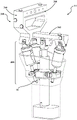
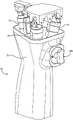
In one exemplary configuration, the instrument 14 is best shown in fig. 8-19. The instrument 14 includes a hand-held portion 16 for holding by a user, a knife support 18 movably coupled to the hand-held portion 16 to support a knife 20, an actuator assembly 400 having a plurality of actuators 21, 22, 23 operatively interconnecting the knife support 18 and the hand-held portion 16 to move the knife support 18 in three degrees of freedom relative to the hand-held portion 16, and a restraint assembly 24 having a passive linkage 26 operatively interconnecting the knife support 18 and the hand-held portion 16.
The hand-held portion 16 includes a grip 72 for grasping by a user so that the user can manually support the instrument 14. The hand-held portion 16 may be configured with ergonomic features, such as a grip for holding the user's hand, a textured coating or a hybrid material coating for preventing slippage of the user's hand when wet and/or bloody. The handheld portion 16 may include a taper to accommodate users having different hand sizes and be contoured to match the contours of the user's hand and/or fingers. The hand-held portion 16 also includes a base 74, and the grip 72 is attached to the base 74 by one or more fasteners, adhesives, welding, or the like. In the illustrated form, the base 74 includes a sleeve 76 having a generally hollow cylindrical shape. Extending from the sleeve 76 are joint supports 77, 78, 79. The actuators 21, 22, 23 may be movably coupled to the base 74 at joint supports 77, 78, 79 by joints described further below.
In the illustrated form, the actuators 21, 22, 23 comprise electrically powered linear actuators extending between the base 74 and the tool support body 80. When actuated, the effective length of the actuator 21, 22, 23 changes to change the distance between the tool support body 80 and the base 74 along the respective axis of the actuator 21, 22, 23. Thus, the actuators 21, 22, 23 work in concert to change their effective lengths and move the tool support 18 in at least three degrees of freedom relative to the hand-held portion 16. In the illustrated form, three actuators 21, 22, 23 are provided, and they may be referred to as first, second and third actuators 21, 22, 23 or front actuators 21, 22 and rear actuators 23. The effective length of the first, second and third actuators 21, 22, 23 is adjustable along a first axis of activity AA1, a second axis of activity AA2 and a third axis of activity AA3 (see fig. 14). The effective lengths of the first, second and third actuators 21, 22, 23 are independently adjustable to adjust one or more of the pitch orientation, roll orientation and z-axis translation of the tool support 18 relative to the hand-held portion 16, as previously described. In some examples, more actuators may be provided. In some examples, the actuator may comprise a rotary actuator. The actuators 21, 22, 23 may comprise a linkage arrangement of one or more links of any suitable size or shape. The actuators 21, 22, 23 may have any configuration suitable for enabling the tool support 18 to move in at least three degrees of freedom relative to the hand-held portion 16. For example, in some forms, there may be one front actuator and two rear actuators, or some other actuator arrangement.
In this form, the actuators 21, 22, 23 are connected to the base 74 and the tool support body 80 by a plurality of movable joints. The movable joints include a set of first movable joints 92 that couple the actuators 21, 22, 23 to the tool support body 80 at the actuator mounts 86, 88, 90. In one form, as shown in fig. 14 and 16, the first movable joint 92 comprises a movable U-shaped joint. The U-joint includes a first pivot pin 94 and a joint block 96. The first pivot pin 94 pivotally connects the joint block 96 to the actuator mounts 86, 88, 90 via a through hole 98 in the joint block 96. A set screw 100 may secure the first pivot pin 94 to the actuator mounts 86, 88, 90. The U-joint may also include a second pivot pin 104. The joint block 96 has a transverse bore 102 to receive a second pivot pin 104. The second pivot pin 104 has a through hole 103 to receive the first pivot pin 94 such that the first pivot pin 94, the joint block 96 and the second pivot pin 104 form the intersection of a U-shaped joint. The first pivot pin 94 and the second pivot pin 104 of each U-joint define an intersecting pivot axis PA (see fig. 16). A second pivot pin 104 pivotally connects the pivot yokes 106 of the actuators 21, 22, 23 to the joint block 96. In this way, the actuators 21, 22, 23 are able to move in two degrees of freedom relative to the tool support body 80. Other types of movable joints are also contemplated, such as a movable ball joint 105 including a ball having a slot that receives a pin (see, e.g., fig. 20 and 21).
Referring to fig. 14 and 15, the movable joint further includes a set of second movable joints 108 that couple the first two actuators 21, 22 to the base 74 of the hand-held portion 16. In the illustrated form, the second movable joint 108 is supported at the joint supports 77, 78. Each second movable joint 108 comprises a rotary yoke 110 arranged to rotate about a rotation axis SA relative to the base 74 of the hand-held portion 16. Each rotary yoke 110 has a rotary head 112 and a post 114 extending from the rotary head 112 to pivotally engage the base 74 at one of the joint supports 77, 78. A nut 115 is threaded onto one end of the post 114 to capture the post 114 in the base 74 while allowing the respective rotary yoke 110 to rotate freely within its respective joint support 77, 78.
Each second movable joint 108 includes a carrier 116 pivotally coupled to one of the rotary yokes 110. The carrier 116 has an internally threaded through hole 117 to receive the lead screws 150 of the first two actuators 21, 22, as described further below. Each carrier 116 also includes opposing trunnions 118 that allow the carrier 116 to pivot relative to the rotating yoke 110 about a pivot axis PA (see fig. 14) by being seated in pockets 120 on the rotating yoke 110. In some forms, for each second movable joint 108, the axis of rotation SA intersects the pivot axis PA to define a single vertex about which the actuators 21, 22 move in two degrees of freedom.
A cap 122 is secured to the rotating head 112 and defines one of the pockets 120, while the rotating head 112 defines the other pocket 120. During assembly, the carrier 116 is first positioned with one of the trunnions 118 placed in the pocket 120 on the rotating head 112, and then the cap 122 is secured over the other trunnion 118 such that the carrier 116 is captured between the cap 122 and the rotating head 112 and is able to pivot relative to the rotating yoke 110 via the trunnion 118 and the pocket 120. Due to the configuration of the rotary yoke 110 and the associated carrier 116, i.e. the carrier 116 is able to rotate about the rotation axis SA and pivot about the pivot axis PA, the second movable joint 108 allows two degrees of freedom of movement of the first two actuators 21, 22 relative to the base 74. Other joint arrangements between the first two actuators 21, 22 and the base 74 are also possible.
The movable joint also includes a third movable joint 124 that couples the rear (third) actuator 23 to the base 74 of the hand-held portion 16. In the illustrated form, the third movable joint 124 is supported at the joint support 79. The third movable joint 124 includes a pivot housing 126 secured to the joint support 79 of the base 74.
Third movable joint 124 includes carrier 116 pivotally coupled to pivot housing 126 by trunnion 118. A fastener 130 having a pocket 132 is attached to either side of the pivot housing 126 via a through hole 133 to engage the trunnion 118. The fasteners 130 are arranged to enable the carrier 116 to pivot via the trunnions 118 located in the pockets 132 after assembly. The carrier 116 has an internally threaded through hole 117 to receive the lead screw 150 of the rear actuator 23, as described further below. Due to the configuration of the pivot housing 126 and associated carrier 116, i.e., the ability of the associated carrier 116 to pivot (e.g., rather than rotate) about the pivot axis PA, the third movable joint 124 allows only one degree of freedom of movement of the rear actuator 23 relative to the base 74. Other joint arrangements between the rear actuator 23 and the base 74 are also possible.
Referring to fig. 16, each of the actuators 21, 22, 23 includes a housing 134. Housing 134 includes a barrel 136 and a cap 138 threaded to barrel 136. The pivot yoke 106, which forms part of the first movable joint 92, is fixed to the housing 134 such that the housing 134 and the pivot yoke 106 are movable together relative to the tool support 18 by the first movable joint 92. The cap 138 captures an annular shoulder 140 of the pivot yoke 106 to secure the pivot yoke 106 to the barrel 136.
In some forms, the pivot yokes 106 and the barrels 136 include one or more alignment features to align each pivot yoke 106 to its respective barrel 136 in a predefined relative orientation. Such alignment features may include mating portions, keys/keyways, and the like. During assembly, the pivot yoke 106 may first be secured to the barrel 136 in its predefined relative orientation, and then the cap 138 may be threaded onto the barrel 136 (e.g., via mating external and internal threads) to capture the pivot yoke 106 to the barrel 136 in the predefined relative orientation. Such a predefined relationship may facilitate routing and/or aligning the flex circuit FC, prevent the pivot yoke 106 from rocking relative to the barrel 136, and/or for other purposes.
Each of the actuators 21, 22, 23 further includes a motor 142 disposed in each housing 134. The motor 142 has a housing 144 disposed in the housing 134 and a motor winding assembly 146 disposed within the housing 144. Motor winding assembly 146 may also be aligned to barrel 136 in a predefined relative orientation, such as by set screws SS (see fig. 16) or other alignment features such as those described above. Each motor 142 also has a rotor 148 secured to a lead screw 150. The lead screw 150 is supported for rotation within the housing 134 by one or more bushings and/or bearings 151. The rotor 148 and associated lead screw 150 are configured to actuate relative to the housing 134 upon selective energization of the motor 142. The lead screw 150 has a fine pitch and lead angle to prevent backdrive (i.e., they are self-locking). Thus, the load placed on the tool 20 does not easily back drive the motor 142. In some examples, the lead screw 150 has an 8-36 step 3 thread with a lead from 0.02 to 0.03 inches/revolution. Other thread types/sizes may also be employed.
Each of the actuators 21, 22, 23 may be controlled by a separate motor controller. The motor controller may be connected to the actuators 21, 22, 23, respectively, to individually direct each actuator 21, 22, 23 to a given target position. In some examples, the motor controller is a Proportional Integral Derivative (PID) controller. In some examples, the motor controller may be integrated with the instrument controller 28 or form a portion of the instrument controller 28. For ease of illustration, the motor controller will be described herein as part of the instrument controller 28.
The power supply provides, for example, a 32VDC power signal to the motor 142 through the console 33. The 32VDC signal is applied to the motor 142 by the instrument controller 28. The instrument controller 28 selectively provides a power signal to each motor 142 to selectively activate the motors 142. This selective activation of the motor 142 serves to position the cutter 20. The motor 142 may be any suitable type of motor including a brushless DC servo motor, other forms of DC motors, and the like. The power source also provides power to the instrument controller 28 to power the components within the instrument controller 28. It should be understood that the power supply may provide other types of power signals, such as 12VDC, 24VDC, 40VDC, etc.
One or more sensors S (see also fig. 7) transmit signals back to the instrument controller 28 so that the instrument controller 28 can determine the current position (i.e., the measured position) of the associated actuator 21, 22, 23. The levels of these signals may vary in relation to the rotational position of the associated rotor 148. In one embodiment, the sensor S may resolve the rotational position of the rotor 148 within a given turn with high resolution. These sensors S may be hall effect sensors that output analog and/or digital signals based on sensed magnetic fields from the rotor 148, or from other magnets placed on the lead screw 150 (see, e.g., the 2-pole magnet MG in fig. 16). A low voltage signal, such as 5VDC, for energizing the hall effect sensors may be supplied from a motor controller associated with the motor 142 associated with the hall effect sensors. In some examples, two hall effect sensors are disposed in the housing 134 and spaced 90 degrees from each other around the rotor 148 to sense the rotor position so that the instrument controller 28 can determine the position of the rotor 148 and calculate an increased number of turns of the rotor (one such sensor S and magnet MG is shown in fig. 16). In some forms the hall effect sensor outputs a digital signal representative of the incremented count. Various types of motors and sensor arrangements are possible. In some examples, the motor 142 is a brushless DC servo motor and the two or more internal hall effect sensors may be spaced 90 degrees, 120 degrees, or any other suitable spacing from each other around the rotor 148. The sensor S may also include an absolute or incremental encoder that may be used to detect the rotational position of the rotor 148 and count the number of turns of the rotor 148. Other types of encoders may also be used as the one or more sensors. The sensors may be placed at any suitable location on the actuators and their surrounding components, suitable for determining the position of each actuator as it is adjusted, e.g., on the housing, nut, screw, etc. In yet another configuration, sensorless motor control may be used. In such an embodiment, the position of each rotor may be determined by measuring the back emf and/or inductance of the motor. One suitable example can be found in U.S. patent No.7,422,582, which is incorporated herein by reference in its entirety.
In some examples, the output signal from the hall effect sensor is sent to the instrument controller 28. The instrument controller 28 monitors the level of the received signal for changes. Based on these signals, the instrument controller 28 determines the rotor position. The rotor position may be considered the number of degrees of rotation of the rotor 148 from an initial or initial position. The rotor 148 may make multiple 360 ° revolutions. The rotor position may therefore exceed 360. A scalar value called a count represents the rotor position from the initial position. The rotor 148 rotates in both clockwise and counterclockwise directions. Each time the signal level of the plurality of signals (analog or digital) undergoes a defined change in state, the instrument controller 28 increments or decrements the count to indicate the change in rotor position. For each full 360 ° rotation of the rotor 148, the instrument controller 28 increments or decrements the value of the count by a fixed count number. In some examples, the count increments or decrements between 100 and 3,000 per 360 degrees of rotation of the rotor 148. In some examples, there are 1,024 positions (counts) per 360 degree rotation of the rotor 148, such as when an incremental encoder is used to monitor rotor position. Internal to the instrument controller 28 is a counter associated with each actuator 21, 22, 23. The counter stores a value equal to the accumulated number of counts that are incremented or decremented. The count value may be a positive number, zero, or a negative number. In some forms, the count value defines an incremental movement of the rotor 148. Thus, the rotors 148 of the actuators 21, 22, 23 may first be moved to a known position, referred to as their initial position (described further below), while the count value is used to define the current position of the rotors 148.
As previously described, the carrier 116 has an internally threaded through hole 117 to threadably receive the lead screws 150 such that each lead screw 150 is rotatable relative to a respective one of the carriers 116 for adjusting the effective length of a respective one of the plurality of actuators 21, 22, 23 to change the count measured by the instrument controller 28. Each of the housing 134 and the corresponding carrier 116 are constrained from relative movement in at least one degree of freedom to allow the lead screw 150 to rotate relative to the carrier 116. More specifically, the lead screw 150 is able to rotate relative to the carriage 116 because: the pivoting yoke 106 is not able to rotate about the associated movable axes AA1, AA2, AA3 (i.e., the pivoting yoke 106 is constrained from such rotational movement due to the configuration of the first movable joint 92); and the carrier 116 cannot rotate about the associated active axes AA1, AA2, AA3 (i.e., the carrier 116 is constrained from such rotational movement due to the configuration of the second active joint 108 and the third active joint 124).
A stop 152, such as a threaded fastener and a shoulder formed on the lead screw 150, is secured to the lead screw 150. The stop 152 is sized to abut the carrier 116 at the end of travel of each lead screw 150.
As previously mentioned, the effective length of the actuators 21, 22, 23 is actively adjustable to enable the tool support 18 to move relative to the hand-held portion 16. One example of this effective length is labeled "EL" on the third actuator 23 in fig. 16. Here, the effective length EL is measured from the center of the associated carrier 116 to the center of the associated first movable joint 92. As each actuator 21, 22, 23 is adjusted, the effective length EL changes by changing how far the lead screw 150 is screwed into or out of its associated carrier 116, thereby changing the distance from the center of the associated carrier 116 to the center of the associated first movable joint 92. The actuators 21, 22, 23 are adjustable between a minimum value and a maximum value of the effective length EL. The effective length EL of each actuator 21, 22, 23 may be expressed/measured in any suitable manner to express the distance between the knife support 18 and the hand-held portion 16 along the active axes AA1, AA2, AA3 that changes to cause various movements of the knife support 18 relative to the hand-held portion 16.
The restraint assembly 24 cooperates with the actuators 21, 22, 23 to restrain the movement provided by the actuators 21, 22, 23. The actuators 21, 22, 23 provide movement in three degrees of freedom, while the restraint assembly 24 restrains movement in three degrees of freedom. In the illustrated form, the restraint assembly 24 includes the passive linkage 26, and a passive linkage joint 156 that couples the passive linkage 26 to the tool support 18.
In one form, as shown in fig. 14 and 16, the passive linkage joint 156 comprises a passive link U-joint. The U-joint includes a first pivot pin 158 and a joint block 160. The first pivot pin 158 pivotally connects the joint block 160 to the passive linkage mount 162 of the tool support body 80 via a through hole 164 in the joint block 160. A set screw 166 may secure the first pivot pin 158 to the passive linkage mount 162. The U-joint further comprises a second pivot pin 170. The joint block 160 has a cross bore 168 for receiving a second pivot pin 170. A second pivot pin 170 pivotally connects a passive linkage pivot yoke 172 of the passive linkage 26 to the joint block 160. The second pivot pin 170 has a through hole 171 to receive the first pivot pin 158 such that the first pivot pin 158, the joint block 160, and the second pivot pin 170 form the intersection of a U-shaped joint. The first pivot pin 158 and the second pivot pin 170 define an intersecting pivot axis PA (see fig. 16). In this way, the passive linkage 26 is able to move in two degrees of freedom relative to the tool support body 80. Other types of passive linkage joints are also contemplated, such as a passive linkage ball joint 107 including a ball with a slot that receives a pin (see, e.g., fig. 20 and 21).
The passive linkage 26 includes a shaft 174 that is fixed to the passive linkage pivot yoke 172. The passive linkage 26 also includes a sleeve 76 of the base 74 configured to receive a shaft 174 along the constraint axis CA. The passive linkage 26 is configured to allow the shaft 174 to slide axially along the constraint axis CA relative to the sleeve 74 and to constrain movement of the shaft 174 radially relative to the constraint axis CA during actuation of one or more of the actuators 21, 22, 23.
The passive linkage 26 also includes a key 176 to constrain rotation of the shaft 174 relative to the sleeve 76 about the constraint axis CA. The keys 176 are best shown in fig. 16. The keys 176 fit in opposing keyways 178, 180 on the shaft 174 and the sleeve 76 to lock the shaft 174 to the sleeve 76 against relative rotation. Other arrangements for preventing relative rotation of the shaft 174 and the sleeve 76 are also contemplated, such as an integral key/slot arrangement or the like. The passive linkage 26 operatively interconnects the tool support 18 and the hand-held portion 16 independently of the actuators 21, 22, 23. The effective length EL of the passive linkage is passively adjustable along the constraint axis CA during actuation of one or more of the actuators 21, 22, 23. The sleeve 76, shaft 174 and key 176 represent one linkage combination for the passive linkage 26. Other sizes, shapes and numbers of links connected in any suitable manner may be used for the passive linkage 26.
In the illustrated form, the passive linkage joint 156 is pivotable relative to the tool support 18 about two pivot axes PA. Other configurations are also possible.
Further, in the illustrated form, the first movable joint 92 and the passive linkage joint 156 define a pivot axis PA (see fig. 9 and 11) disposed on the common plane CP. Non-parallel pivot axes PA, parallel pivot axes PA arranged on different planes, combinations thereof, and/or other configurations are also contemplated.
In some forms, the head 84 of the tool support 18 is arranged such that the tools 20 lie on a tool plane TP (e.g., a blade plane) that is parallel to the common plane CP when the tools 20 are coupled to the tool support 18 (see fig. 9 and 11). In some examples, the tool plane TP is spaced apart from the common plane CP by 2.0 inches or less, 1.0 inches or less, 0.8 inches or less, or 0.5 inches or less.
Referring to fig. 10, 14 and 16, the constraint axis CA and the third activity axis AA3 may be positioned coplanar along the vertical center plane VCP throughout actuation of the actuators 21, 22, 23. Other configurations are also contemplated, including those in which the constraint axis CA and the third activity axis AA3 are not coplanar.
In the illustrated form, the actuators 21, 22, 23 are arranged so that in all positions of the actuators 21, 22, 23 (including in their initial position) the active axes AA1, AA2, AA3 are in an inclined configuration with respect to the constraint axis CA. Tilting axes AA1, AA2, AA3 generally tapers the actuator arrangement to allow the base 74 and associated grip 72 to be slimmer and more compact. Other configurations may be envisaged, including those in which the active axes AA1, AA2, AA3 are not in an inclined configuration with respect to the constraint axis CA. Such configurations may include configurations in which the actuator axes AA1, AA2, AA3 are parallel to each other in their initial positions.
Other configurations of actuators, movable joints, and restraint assemblies are possible. In some forms, the restraining assembly may not be present and the knife support 18 of the instrument 14 is able to move in an additional degree of freedom relative to the hand-held portion 16. Further, as described above, the actuator assembly described below may be used.
Virtual boundaries
The software used by control system 60 to control the operation of instrument 14 includes boundary generator 182 (see fig. 7). Boundary generator 182 may be implemented on instrument controller 28, navigation controller 36, and/or on other components (e.g., on a separate controller). Boundary generator 182 may also be part of a separate system that is operated remotely from instrument 14. Referring to FIG. 22, boundary generator 182 is a software program or module that generates one or more virtual boundaries 184 for constraining the movement and/or operation of instrument 14. In some examples, boundary generator 182 provides a virtual boundary 184 that defines a virtual cutting guide (e.g., a virtual saw cutting guide). A virtual boundary 184 may also be provided to delineate various operating/control regions as described below. The virtual boundary 184 may be one-dimensional (1D), two-dimensional (2D), three-dimensional (3D), and may include points, lines, axes, trajectories, planes (infinite planes or planar segments bounded by anatomical structures or other boundaries), volumes, or other shapes, including complex geometric shapes. The virtual boundary 184 may be represented by pixels, point clouds, voxels, triangular meshes, other 2D or 3D models, combinations thereof, and the like. U.S. patent publication No.2018/0333207 and U.S. patent No.8,898,043 are incorporated herein by reference, and any of their features may be used to facilitate planning or performing a surgical procedure.
The virtual boundary 184 may be used in various ways. For example, the control system 60 may: controlling certain movements of the tool 20 to stay within the boundaries; controlling certain movements of the tool 20 to stay outside the boundaries; control certain movements of the tool 20 to stay on the boundary (e.g., remain on a point, track, and/or plane); controlling certain movements of the tool 20 to approach a boundary (attraction boundary) or to repel from a boundary (repulsion boundary); and/or control certain operations/functions of instrument 14 based on the relationship of instrument 14 to the boundary (e.g., space, velocity, etc.). Other uses of the boundary 184 are also contemplated.
In some examples, one of the virtual boundaries 184 is a desired cutting plane, as shown in fig. 22. In some forms, control system 60 is primarily used to maintain tool 20 in a desired cutting plane. The virtual boundary 184 that controls the positioning of the cutter 20 may also be a volumetric boundary, for example, the thickness of the volumetric boundary is slightly greater than the thickness of the blade to constrain the blade to stay within the boundary and on the desired cutting plane, as shown in FIG. 2. Thus, the desired cutting plane may be defined by a virtual plane boundary, a virtual volume boundary, or other form of virtual boundary. Virtual boundary 184 may also be referred to as a virtual object. The virtual boundary 184 may be defined relative to the anatomical model AM, e.g. a 3D bone model (see fig. 22, which illustrates that the anatomical model AM is virtually overlaid on the real femur F due to their registration). In other words, the points, lines, axes, trajectories, planes, volumes, etc. associated with the virtual boundary 184 may be defined in a coordinate system that is fixed relative to the coordinate system of the anatomical model AM, such that tracking of the anatomical model AM (e.g., by tracking the associated anatomical structure to which it is registered) also enables tracking of the virtual boundary 184.
The anatomical model AM is registered to the first patient tracker 54 such that the virtual boundary 184 is associated with the anatomical model AM and the associated coordinate system. The virtual boundary 184 may be implant-specific, e.g., defined based on the size, shape, volume, etc. of the implant, and/or may be patient-specific, e.g., defined based on the anatomy of the patient. The virtual boundary 184 may be a boundary created pre-operatively, intra-operatively, or a combination thereof. In other words, the virtual boundary 184 may be defined prior to the start of the surgical procedure, during the surgical procedure (including during tissue removal), or a combination thereof. The virtual boundaries 184 may be provided in a variety of ways, such as by the control system 60 creating them, receiving them from other sources/systems, and so forth. The virtual boundary 184 may be stored in memory for retrieval and/or updating.
In some cases, such as when preparing the femur F to receive a total knee implant IM (see fig. 1), the virtual boundary 184 includes a plurality of planar boundaries that can be used to delineate a plurality of cutting planes (e.g., five cutting planes) for the total knee implant IM and are associated with a 3D model of the distal end of the femur F. These multiple virtual boundaries 184 can be activated by the control system 60 one at a time to constrain the cut to one plane at a time.
Referring back to fig. 7, two additional software programs or modules are run on the instrument controller 28 and/or the navigation controller 36. A software module performs behavior control 186. Behavior control 186 is the process of calculating data indicative of the next command/desired position and/or orientation (e.g., desired pose) of tool 20. In some cases, only the desired position of TCP is output from behavior control 186, and in some cases, the commanded pose of tool 20 is output. The output from the boundary generator 182 (e.g., the current position and/or orientation of the virtual boundary 184 in one or more coordinate systems) may be fed as input into the behavior control 186 to determine the next commanded position of the actuators 21, 22, 23 and/or the orientation of the tool 20. Behavior control 186 may process this input, along with one or more other inputs described further below, to determine a command gesture.
The instrument controller 28 may control the one or more actuators 21, 22, 23 to adjust the tool 20 toward a desired pose by sending command signals to each actuator 21, 22, 23. The instrument controller 28 may know that the actuators 21, 22, 23 may adjust the entire length of the tool support 18 relative to the hand-held portion 16. In some examples, the instrument controller 28 knows the entire length that the actuators 21, 22, 23 can adjust and can send command signals to the actuators 21, 22, 23 to move them a measured distance from one location to another. The measured position may be a known position or a distance between the current positioning of the actuator 21, 22, 23 and an actuator limit. Each position to which the actuator 21, 22, 23 is moved may be a measured distance from the positive and negative limits of actuator travel (i.e. the position between the two ends of the lead screw). The instrument controller 28 may command the actuators 21, 22, 23 to and from the measurement position, as described below.
In some examples, when one or more of the actuators 21, 22, 23 have reached their limits, the instrument controller 28 may require the hand-held portion 16 to make an adjustment in order to bring the tool 20 back within a range where the actuator can adjust the tool 20 toward a desired pose. In this case, the simulated command positions may be used to indicate to the user how to move the hand-held portion 16 in order to bring the tool 20 and actuators 21, 22, 23 back into alignment with the desired pose. The simulated command position may be a position determined by the instrument controller 28 in conjunction with navigation data from the navigation system 32, where the hand-held portion 16 must be moved in order to adjust the tool 20 toward the desired pose without adjusting the actuators 21, 22, 23. The simulated command position works with the steering array 200, the indicators 201, 202, 203, or both to signal to the user: the hand-held portion 16 needs to be moved in a particular manner to place the tool 20 in the desired pose. In some examples, the guide array 200, the indicators 201, 202, 203, or both signal the user to move the hand-held portion 16 in the same manner as the actuators 21, 22, 23 adjust the tool 20, but rely on the user correcting the pose of the tool 20 by manipulating the hand-held portion 16 while the actuators remain in place.
The second software module performs motion control 188. One aspect of motion control 188 is control of instrument 14. Motion control 188 receives data defining the next command gesture from behavior control 186. Based on these data, the motion control 188 determines the next rotor position of the rotor 148 of each actuator 21, 22, 23 (e.g., via inverse kinematics) so that the instrument 14 can position the tool 20 as commanded by the behavior control 186, e.g., at a commanded pose. In other words, the motion control 188 processes the commanded pose, which may be defined in cartesian space, into an actuator position (e.g., a rotor position) of the instrument 14 such that the instrument controller 28 may accordingly command the motor 142 to move the actuators 21, 22, 23 of the instrument 14 to a commanded position, such as a commanded rotor position corresponding to the commanded pose of the tool 20. In one form, the motion control 188 adjusts the rotor position of each motor 142 and continuously adjusts the torque output by each motor 142 to ensure as much as possible that the motor 142 drives the associated actuator 21, 22, 23 to the commanded rotor position.
In some forms, for each actuator 21, 22, 23, the instrument controller 28 determines a difference between the measured position and the commanded position of the rotor 148. The instrument controller 28 outputs a target current (proportional to the torque of the rotor), varying the voltage to adjust the current at the actuator from the initial current to the target current. The target current effects movement of the actuators 21, 22, 23 to move the tool 20 from the measurement attitude to the commanded attitude. This may occur after the commanded pose is converted to a joint position. In one example, the measured position of each rotor 148 may be derived from a sensor S, such as an encoder, as described above.
The boundary generator 182, behavior control 186, and motion control 188 may be a subset of a software program. Alternatively, each may be a software program that runs independently, alone and/or in any combination thereof. The term "software program" is used herein to describe computer-executable instructions configured to perform the various capabilities of the described aspects. For simplicity, the term "software program" is intended to encompass at least any one or more of the boundary generator 182, the behavior control 186, and/or the motion control 188. The software program may be implemented on instrument controller 28, navigation controller 36, or any combination thereof, or may be implemented by control system 60 in any suitable manner.
A clinical application 190 may be provided to handle user interaction. The clinical application 190 handles many aspects of user interaction and coordinates surgical workflow including preoperative planning, implant placement, registration, bone preparation visualization, post-operative assessment of implant fitness, and the like. The clinical application 190 is configured for output to the display 38. The clinical application 190 may run on its own separate processor or may run in conjunction with the instrument controller 28 and/or the navigation controller 36. In one example, the clinical application 190 interfaces with the boundary generator 182 after the user sets implant placement and then sends the virtual boundary 184 returned by the boundary generator 182 to the instrument controller 28 for execution.
Homing
Before the anatomical structure is treated (e.g., before the femur F and/or tibia T are cut), and during certain modes of operation described below, a homing procedure may be performed that establishes an initial position of the cutter 20 by placing each actuator 21, 22, 23 at their respective initial positions. This process is used to provide a reference position from which to count the incremental movements of the rotor 148 measured by the sensor S so that the control system 60 can determine the current position of the rotor 148. In some forms, homing may not be necessary when the sensor S is capable of measuring the absolute position of the rotor 148. In effect, the homing process creates an initial rotor position (zero position) of the actuators 21, 22, 23. The initial position is actually the rotor 148 position that provides the greatest possible amount of travel in each direction along the active axes AA1, AA2, AA 3. In some examples, the initial position is generally positioned such that the initial point HP of the lead screw 150 (centrally disposed midway between the stops 152) is centrally disposed in the associated carrier 116 (see fig. 16, which shows the two actuators 22, 23 in their initial positions). Even when a homing procedure is not used, such as using an absolute encoder, it may include setting the actuators 21, 22, 23 to the initial point HP before or after performing other modes (e.g., a proximity mode, described further below). The instrument controller 28 may be configured to control the actuators 21, 22, 23 to their initial positions between the minimum and maximum values of the effective length EL of the actuators 21, 22, 23.
When in the initial position, the adjustable amount of the actuators 21, 22, 23 is maximized to maintain the tool 20 in the desired attitude. Various levels of adjustment are possible depending on the particular geometry and configuration of the instrument 14. In some examples, when all of the actuators 21, 22, 23 are in their initial positions, the pitch orientation of the tool 20 may be adjusted +/-18 ° from the initial positions, assuming the change in yaw orientation is zero and there is no z-axis translation. In some examples, when all of the actuators 21, 22, 23 are in their initial positions, the roll orientation of the tool 20 may be adjusted +/-33 ° from the initial positions, assuming zero change in pitch orientation and no z-axis translation. In some examples, when all of the actuators 21, 22, 23 are at their initial positions, the z-axis translation of the tool 20 may be adjusted +/-0.37 relative to the initial positions, assuming zero change in pitch and yaw orientations. Of course, during operation, the tool 20 may be adjusted in pitch, yaw, and z-axis translation simultaneously, sequentially, or a combination of both.
The homing procedure for each actuator 21, 22, 23 may be performed sequentially, simultaneously or in any desired order. In some cases, during the homing procedure, the instrument controller 28 actuates each motor 142. The motor 142 is actuated to rotate its associated lead screw 150, causing relative axial displacement between the lead screw 150 and the associated carriage 116 along the associated movable axis AA1, AA2, AA3 in each axial direction until the stop 152 and the carriage 116. Such contact may be determined by additional sensors S, by monitoring the current of the motor 142 (e.g., a current spike exceeding a threshold indicating that the stop 152 has been reached), and so forth. For example, the motor 142 may actuate the lead screw 150 until one of the stops 152 engages the carriage 116, at which point the cumulative count and associated end rotor position are stored. It is also possible, but not necessary, to set a counter storing a cumulative count representing the rotor position to zero when the first stop 152 is reached. The motor 142 may then actuate the lead screw 150 in the opposite direction until another stop 152 engages the carrier 116. During this time period, the instrument controller 28 monitors the signal from the sensor S to count the number of turns of the rotor 148 until the other end rotor position is reached. Instrument controller 28 maintains a count in a counter that represents the total number of degrees of rotation of lead screw 150 (e.g., its shaft) between stops 152. The initial position is the average of these counts or the average rotor position between stops 152.
In some examples, the instrument controller 28 stores as data a cumulative count representing the rotations of the rotor 148 required to shift the lead screw 150 between the respective end rotor positions (e.g., between limits of travel). The absolute difference between the two counts is calculated. This difference is divided by two. This value represents the number of counts through which the rotor 148 must cycle from its current position in order to center the initiation point HP in the carriage 116 to the initiation position. For example, during this process, the instrument controller 28 may receive an indication that: at one end rotor position, the value counted is 2500; at the other end rotor position, the count is-1480. The difference between the values of these counts was 3980. Half of this difference is 1990. Thus, the value of the average count between each end rotor position may be calculated as-1480 +1990 ═ 510. This number is called the target position. During homing, the target position is a positive or negative number equal to the accumulated count representing the initial position. The instrument controller 28, in turn, applies an excitation signal to the motor 142 to cause the rotor 148 to rotate toward the count representing the initial position.
During the resulting rotation of the rotor 148, the changing value of the sensor S results in a count output that changes the count value stored in the counter. During this step, the instrument controller 28 compares the accumulated count stored in the counter with the count represented by the initial position. When the two values are equal, the instrument controller 28 terminates the application of the excitation signal to the motor 142. The instrument controller 28 may also set the counter to zero in the initial position. It will be appreciated that such rotation of the rotor 148 and, by extension, the lead screw 150 causes the lead screw 150 to displace relative to the carriage 116 along the active axes AA1, AA2, AA3 to its initial position. Once the actuators 21, 22, 23 are in their initial positions, soft stops may be activated to prevent the stops 152 (e.g., hard stops) from contacting the carrier 116 at the extreme ends of travel. A soft stop may be a software enabled stop set at a count value just below the extreme end of travel measured in the homing procedure. The soft stop may be a value pre-programmed into the software. The soft stop may be a combination of a count value and a preprogrammed value.
As shown in fig. 16, each of the actuators 21, 22, 23 has an effective length EL. The effective length EL at the initial position may be any suitable length. In some examples, the effective length EL at the initial position may be about 2.14 inches, and the minimum/maximum value of the effective length EL when engaging the hard stop 152 may be about 1.72 and 2.56 inches, respectively. When a soft stop is used, the minimum/maximum value of the effective length EL may be about 1.78 inches and 2.50 inches, respectively. It should be understood that these values are merely examples, and that other values are contemplated.
In some examples, each incremental count associated with a rotation of the rotor 148 that causes the rotor 148 to be displaced toward the carrier 116 is a positive incremental count, and each incremental count associated with a rotation of the rotor 148 that causes the rotor 148 to be displaced away from the carrier 116 is a negative incremental count. The instrument controller 28 is thus able to provide cumulative count data representative of the rotor position.
When the actuators 21, 22, 23 are in their initial positions or other predetermined positions, the initial position of the base coordinate system BCS can be determined based on the known geometrical relationship between the tool support coordinate system TCS and the base coordinate system BCS. This relationship changes as the actuators 21, 22, 23 are adjusted, and the associated changes may be determined based on the kinematics of the robotic system 10 (e.g., establishing a dynamic transformation between these coordinate systems). Alternatively or additionally, another tracker may be attached and fixed relative to the base coordinate system BCS to directly track the pose of the base coordinate system BCS relative to the tool support coordinate system TCS. Thus, the robotic system 10 knows the position of the tool 20, e.g., at an initial position and its relationship to the pose of the hand-held portion 16. Thus, when the user moves tool 20 and tracks its pose using tool tracker 52, robotic system 10 also tracks the pose of hand-held portion 16 and its base coordinate system BCS. In some examples, the position of the tool 20 relative to the tool support 18 is assumed to be known as a result of a previous calibration process.
In some forms, the initial position is determined by first determining the pose of the hand-held portion 16 relative to the tool support 18 (e.g., relative to the tool support coordinate system TCS) in a common coordinate system (e.g., of the base coordinate system BCS) using a separate tracker (see fig. 60) fixed to the hand-held portion 16. This spatial relationship between the hand-held portion 16 and the tool support 18 may also be determined by using registration of the pointer 57 with known alignment indentations on the hand-held portion 16 or by other navigation methods. The current rotor position of each of the actuators 21, 22, 23 may then be derived from this spatial relationship based on the kinematics of the instrument 14. Knowing the current rotor position and using the encoder (and corresponding encoder signal) to measure the change from the current rotor position, the instrument controller 28 may then operate each actuator 21, 22, 23 until they reach their initial positions. The initial position may be stored in a memory of the instrument controller 28.
In essence, instrument controller 28 utilizes tracking data obtained by navigation system 32 from tracker 52 coupled to tool support 18 and hand-held portion 16 on instrument 14 to determine the position of actuators 21, 22, 23 so that the incremental encoder can thereafter operate as an absolute encoder.
Once registration, calibration, and homing (if used) is complete, the navigation system 32 can determine the spatial pose of the tool 20 relative to the anatomy (e.g., relative to the femur F or other target tissue) and the one or more virtual boundaries 184. Such that instrument 14 is ready for anatomical boundary constraint therapy (e.g., instrument 14 is ready to cut a target volume of material from femur F). Even without using a homing procedure (e.g. absolute encoder) as defined above, the actuators 21, 22, 23 may still be set to their initial positions before or after execution, other operation modes (e.g. proximity mode).
After the homing process, control is performed based on position and/or orientation data from the navigation controller 36 and accumulated count data from the instrument controller 28 or other position data of the actuator. Control may also be based on user input, for example, from a trigger or other input device, such as a foot pedal. In some examples, the instrument 28 may be automatically operated based on the pose of the tool 20 relative to the anatomy being treated, as described further below.
Control of the instrument 14 takes into account the anatomy (e.g., femur F) and the latest position and/or orientation of the instrument 14, which are transmitted from the navigation controller 36 to the instrument controller 28 over the data connection. Using this data, instrument controller 28 determines the location (i.e., position and/or orientation) of virtual boundary 184 in the desired coordinate system. The relative positioning of the tool 20 (e.g., TCP) to the virtual boundary 184 is also calculated. The instrument controller 28 updates the navigation system 32 (including the display 38) with the position and/or orientation of the tool 20 relative to the anatomy to which the tool 20 is to be applied. An indication of the location of the virtual boundary 184 may also be presented.
The relative positioning of tool 20 to virtual boundary 184 is evaluated by instrument controller 28 to determine whether action needs to be taken, i.e., moving tool 20, changing the speed (e.g., swing speed) of tool 20, stopping operation of tool 20, etc. For example, command packets are sent to a motor controller, such as from console 33 or other components of instrument controller 28. These command data packets include a target position of the rotor 148 of the motor 142 (or a target position of the actuator). Here, each target position may be a positive or negative number representing a target cumulative count of the associated rotor 148. The console 33 or other component of the instrument controller 28 generates and sends these command packets to each motor controller at a rate of one packet every 0.05 to 4 milliseconds. In some examples, each motor controller receives a command packet at least once every 0.125 milliseconds. Instrument controller 28 may also selectively adjust the cutting speed of instrument 14 based on the relative positioning of tool 20 and one or more of the virtual boundaries 184. For example, the drive motor M that controls the oscillation and corresponding cutting of the knife 20 may be disabled by the instrument controller 28 whenever the knife 20 is in an undesirable relationship relative to the virtual boundary 184 (e.g., the knife 20 deviates from the target plane by more than a threshold).
During use, when the robotic system 10 determines the pose (current pose) of the tool 20 with the navigation system 32 by means of the tracker 52 positioned on the tool support 18. The instrument controller 28 may also determine the current position of each of the actuators 21, 22, 23 based on output encoder signals from the one or more encoders located on each of the actuators 21, 22, 23. Upon receiving the current position of each actuator 21, 22, 23, the instrument controller 28 may calculate the current pose of the hand-held portion 16 (e.g., the current pose of the base coordinate system BCS relative to a desired coordinate system, such as the TCP coordinate system), using forward kinematics to convert the actuator position to a pose (TCP relative to BCS). Once the instrument controller 28 has the current relative poses of the tool support 18 and the hand-held portion 16 in the desired coordinate system, the instrument controller 28 may then determine the commanded pose of the tool 20 based on the current pose of the tool 20 as determined by the navigation system 32, the current pose of the hand-held portion 16 calculated from the current position of each of the actuators 21, 22, 23, and based on the position and/or orientation of the planned virtual object (as the desired cutting plane). The instrument calculates the pose (command pose) of the TCP relative to the BCS, which causes the TCP to lie on the desired plane or to align with the planned virtual object. Instrument controller 28 may send command instructions to actuators 21, 22, 23 to move to command positions to change the pose of tool support 18 and tool 20. In one example, the commanded pose of the knife 20 is further based on the target cutting plane, so the instrument controller 28 calculates the current pose of the knife support 18 and the current positions of the actuators 21, 22, 23 to determine the current pose of the handheld portion 16. Once the current pose of the tool support 18, the current position of the actuators 21, 22, 23, and the current pose of the hand-held portion 16 are known, the instrument controller 28 may send command signals to the actuators 21, 22, 23 to adjust the tool support 18 and the tool 20 based on the desired plane. The controller calculates the commanded pose assuming that the pose of the handheld portion (BCS) is temporarily (during a single iteration) stationary relative to the patient anatomy. The actual movement of the BCS is adjusted by updating the corresponding pose each time.
Turning to FIG. 64, exemplary controls are described with respect to various transforms. TCP is determined by tracking tool 20 with tracker 52 in LCLZ (LCLZ-TT), and using the registration data to determine a transformation between tool tracker 52 and TCP (TT-TCP) of tool 20 (e.g., saw). Similarly, the patient is tracked using a patient tracker PT (shown as 54) in the LCLZ (LCLZ-PT). A transformation (PT-TP) is determined between the patient tracker PT and each planned virtual object 184(TP) using the registration data and the planning information. As described above, the transformation between BCS and TCP (BCS-TCP) is calculated based on the current position of each actuator (as described above). The transformation between the BCS and TCP is used to relate the various coordinate systems back to the handheld portion 16, as the command poses can be determined relative to the BCS. Conceptually, the command gesture is an update to the BCS to TCP transformation, which in this example results in TCP being aligned with the planned virtual object 184 (target plane TP).
Throughout this specification, any instance of a gesture may be a command gesture, a current gesture, a past gesture, or a past command gesture, unless otherwise specified. While each of these poses may be different from one another, differences in position and/or orientation between these poses may be minimal in each control iteration due to control frequency.
It should be understood that the combination of the position and orientation of an object is referred to as the pose of the object. Throughout this disclosure, it is envisioned that the term pose may be replaced by position and/or orientation, and vice versa, for suitable alternatives to implement the concepts described herein. In other words, any use of the term pose may be replaced with a position, and any use of the term position may be replaced with a pose.
Visual guidance
As shown in fig. 22, guide array 200 may be coupled to tool support 18. Additionally or alternatively, the guide array 200 may be attached to the hand-held portion 16, as shown in fig. 65, or other portions of the instrument 14. In the illustrated form, the guide array 200 includes at least a first visual indicator 201, a second visual indicator 202, and a third visual indicator 203. Each of the visual indicators 201, 202, 203 includes one or more illumination sources coupled to the instrument controller 28. In some forms, the illumination source includes one or more light emitting diodes (e.g., RGB LEDs) that can operate in different states, e.g., on, off, blink/blink at different frequencies, illuminate at different intensities, different colors, combinations thereof, and so forth. In the form shown in FIG. 22, each visual indicator 201, 202, 203 includes upper and lower portions 204, 206 (upper segment 204; lower segment 206). It is further envisioned that each of the visual indicators 201, 202, 203 may be divided into more than two portions 204, 206, such as three or more, four or more, or even ten or more portions. For example, each of the visual indicators 201, 202, 203 may be divided into three portions, each portion including one or more LEDs. The visual indicators 201, 202, 203 may have a generally spherical shape, with the upper and lower portions 204, 206 comprising hemispherical, transparent or translucent domes that may be individually controlled/illuminated as desired. It is contemplated that the visual indicators 201, 202, 203 may have shapes other than spherical, such as cylindrical, circular, square, polygonal, or any other shape capable of conveying a visual cue to a user. One or more light emitting diodes may be associated with each dome. The visual indicators 201, 202, 203 may be secured to the tool support 18 or the hand-held portion 16 by one or more mounting brackets 205.
In some examples where a guide array is not used, the visual indicators 201, 202, 203 may comprise separate portions of a display screen (see fig. 66), such as separate areas on an LCD or LED display mounted to the tool support 18 or hand-held portion 16 (e.g., fig. 66). The display screen may also be included as part of the navigation system, in addition to or instead of having the display screen mounted to the instrument.
In some configurations, there may be one, two, three, or four portions of the display screen, each portion corresponding to a different visual indicator. Each portion of the display screen may correspond to a different visual graphic. As described below, each visual indicator (or portion of the display screen) may be based on actuator information. In some cases, a single visual indicator may be based on actuator information from two or more actuators. Further, as described throughout, the visual indicator may be used in a first mode indicating where the user should position the tool and a second mode where the visual indicator indicates where the user should position the hand-held portion.
For example, the visual indicators 201, 202, 203 may be configured to output a first indication (first visual graphic) based on a first command position of the first actuator 21, 22, 23 and a second indication (second visual graphic) based on a second command position of the first actuator 21, 22, 23, wherein the first indication is different from the second indication and the first command position is different from the second command position. As described above, the visual indicators 201, 202, 203 may be controlled based on any suitable type of actuator information. In other words, the visual graphics displayed on the display screen may be based on the commanded position, a previous commanded position, a simulated commanded position, a current measured position, a previous measured position, an available amount of travel, an actuator limit (e.g., a hard or soft stop), a desired distance from the current position to the commanded position, or a combination thereof.
In some configurations, the instrument controller 28 is configured to control the illumination of the upper and lower portions 204, 206 such that the upper and lower portions 204, 206 operate in different states to indicate a desired direction of movement of the tool 20. It is further contemplated that instrument controller 28 may be configured to control illumination of multiple portions in different states or with different indications. For example, different states may indicate to the user: (1) how the user should move the hand-held portion 16 to place the tool 20 (e.g., a saw blade) in a desired pose (e.g., on a desired cutting plane); or (2) how the user should move the hand-held portion 16 to move the actuators 21, 22, 23 in a preferred direction (e.g., closer to their initial positions), while the control system 60 simultaneously operates to maintain the tool 20 in the desired pose, as will be described further below.
During some modes of operation, the instrument controller 28 is configured to automatically control/adjust the guide array 200 (e.g., change its state) to visually indicate to the user the desired changes in pitch orientation, yaw orientation, and z-axis translation in order to achieve the desired pose of the tool 20 while the user moves the tool 20 through the hand-held portion 16. In some forms, guide array 200 is coupled to knife support 18 or hand held portion 16 in a manner that visually represents the plane of knife 20. For example, since the three points define a plane, the three visual indicators 201, 202, 203 may generally represent the plane of the tool 20. In some cases, each of the indicators 201, 202, 203 corresponds to one of the points P1, P2, P3 having a known position relative to the plane of the tool 20 (e.g., located in the tool plane and defined in a TCP coordinate system, a tool support coordinate system TCS, or in any other suitable coordinate system). In some forms, the indicators 201, 202, 203 correspond to points P4, P5, P6, respectively, of the tool 20, as shown in fig. 23A-23D. The points associated with the visual indicators 201, 202, 203 may be defined at other suitable locations in the plane of the tool 20 or at locations having a known relationship to the plane of the tool 20.
In summary, the guide array 200 using one or more visual indicators 201, 202, 203 may be positioned and their state may be controlled to visually indicate to the user the desired change in movement (e.g., magnitude of travel) for changing the pitch, yaw and translation of the tool 20, and to visually indicate to the user (by extension) the desired change in pitch, yaw and translation of the tool support coordinate system TCS in order to achieve the desired pose. More specifically, the instrument controller 28 is configured to illuminate the guide array 200 in a manner that enables a user to distinguish between a desired change in pitch orientation, a desired change in roll orientation, and a desired change in translation. Instrument controller 28 may be configured to illuminate guide array 200 or control a display screen in a manner that enables a user to indicate the amount of travel required to move tool 20 to a desired plane. The desired plane may be a plane or a plane segment. For example, changes in pitch, yaw, and translation are relative to one or more of the virtual boundaries.
In another configuration, the guide array 200 using one or more visual indicators 201, 202, 203 may be positioned and their state may be controlled to visually indicate to the user the desired change in movement (e.g., amount of travel) for changing the pitch, roll and pan of the handheld portion 16, and to visually indicate to the user (by extension) the desired change in pitch, roll and pan of the base coordinate system BCS in order to achieve the desired pose. More specifically, the instrument controller 28 is configured to illuminate the guide array 200 or display screen in a manner that enables a user to distinguish between a desired change in pitch orientation, a desired change in roll orientation, and a desired change in pan. Instrument controller 28 is configured to illuminate guide array 200 in a manner that enables the user to indicate the amount of travel required to move hand-held portion 16 so that knife 20 is positioned on a desired plane. For example, changes in pitch, yaw, and translation are relative to one or more of the virtual boundaries 184.
Based on an input signal, such as activation of an input device (e.g., foot pedal, trigger, etc.), the instrument controller 28 may switch operation of the guide array 200 and/or visual indicators 201, 202, 203 (or display screen) from a mode in which the guide array/visual indicators indicate a desired change in movement of the tool 20 to a mode indicating a desired change in movement of the hand-held portion 16. Alternatively, the instrument controller 28 may be configured to switch between these modes, e.g., trackers 54, 56, PT, based on the position of the tool 20 and the position of the reference location (reference location) of the bone in a known coordinate system. The reference location may be a point, surface, or volume in the coordinate system used to locate the instrument 14 relative to the target object. For example, the reference location may be a surface of a bone, a point within a bone, a hypothetical or virtual point within a known coordinate system, a volume in a coordinate system, or a combination thereof. The position and/or orientation of the reference locations is known relative to the patient tracker by means of registration and suitable planning steps.
As described below, instrument controller 28 may switch modes based on the distance parameter. The distance parameter may be a distance (e.g., how far two objects are apart), a magnitude (direction of distance relative to one object), or both. In some examples, instrument controller 28 may switch modes when the distance parameter has a direction away from the bone and a magnitude greater than a first threshold. It will be appreciated that in the first mode the instrument controller 28 automatically controls each of the actuators 21, 22, 23 to maintain the tool 20 in a pose relative to the hand-held portion 16, and wherein in the second mode the controller automatically controls each of the actuators 21, 22, 23 such that the pose of the tool 20 relative to the hand-held portion 16 is actively moved towards a desired plane. Automatic switching between modes may provide the user with a type of guidance appropriately determined by proximity to the bone and the cut to be made. In other words, as the instrument 14 approaches the bone, the guide array 200 and/or visual indicators 201, 202, 203 operate to provide precise guidance to ensure that the handheld portion 16 remains positioned in a pose that maximizes the range of motion relative to the desired plane.
In the version shown in fig. 23A-23D, first and second visual indicators 201, 202 are located in front of the hand-held portion 16 and on opposite sides of the instrument 14, generally aligned with the actuators 21, 22, respectively. The third visual indicator 203 is located behind the hand-held portion 16, generally aligned with the actuator 23 and near the rear of the instrument 14, i.e. the first and second visual indicators 201, 202 are located distal to the third visual indicator 203. As shown in fig. 2, the first and second visual indicators 201, 202 are located in front of the y-axis of the tool support coordinate system TCS and the base coordinate system BCS and on opposite sides of the x-axis of the tool support coordinate system TCS and the base coordinate system BCS, when viewed from above and in the initial position. The third visual indicator 203 is located behind the y-axis and aligned with the x-axis when viewed from above and in the initial position. In some examples, when in the initial position, tool support 18 defines a vertical center plane VCP that passes through the x-axis, wherein first and second visual indicators 201, 202 are offset from vertical center plane VCP on opposite sides of vertical center plane VCP, and vertical center plane VCP passes through third visual indicator 203 (see fig. 11). Other arrangements of the visual indicators 201, 202, 203 are contemplated.
In some examples, referring back to fig. 23A-23D, the upper and lower portions 204, 206 may be vertically oriented on a directional axis DA parallel to the z-axis of the tool support coordinate system TCS, and different states (e.g., color, frequency, intensity, etc.) may be displayed in each of the upper and lower portions 204, 206 to indicate the upward/downward direction of desired movement of each visual indicator 201, 202, 203. As a result of this arrangement, for example, when all of the visual indicators 201, 202, 203 are controlled to indicate that downward movement is desired, this indicates that the user should move their hand downward (see the arrow in fig. 23A). Instrument controller 28 may control illumination of upper portion 204 to cause upper portion 204 to operate in a first state and lower portion 206 to operate in a second state different from the first state to indicate to the user to change the translational position of tool 20 and/or hand-held portion 16 relative to virtual boundary 184. In the example shown, the downward direction may be visually indicated by illuminating the upper portion 204 red while the lower portion 206 is illuminated yellow (e.g., yellow over red indicates a direction downward).
The instrument controller 28 may also be configured to control the illumination of the upper portion 204 of the first visual indicator 201 to operate in a first state and the illumination of the upper portion 204 of the second visual indicator 202 to operate in a second state different from the first state to instruct the user to change the rocking orientation of the tool 20. Likewise, the instrument controller 28 may be configured to control the illumination of the upper portion 204 of the third visual indicator 203 to operate in a first state and the illumination of the upper portions 204 of the first and second visual indicators 201, 202 to operate in a second state different from the first state to indicate to the user to change the pitch orientation of the tool 20 relative to the virtual boundary 184. For example, as shown in fig. 23B, when only a slight downward movement and change in pitch orientation is required (see arrows), the first and second visual indicators 201, 202 may be illuminated to show that they still need to move slightly downward, but the third visual indicator 203 may be illuminated in a different manner to show that the rear of the instrument 14 needs to move further downward than the front (i.e., the pitch needs to be changed). In the example shown, a slightly downward direction may be visually indicated by illuminating the upper portion 204 of the first and second visual indicators 201, 202 in yellow and the lower portion 206 in green (e.g., yellow over green indicates the direction is slightly downward). At the same time, the third visual indicator 203 may remain illuminated (e.g., red over yellow) as in fig. 23A to show that further downward movement at the rear is required, and thus visually and intuitively indicate to the user that the implement 14 is to be repositioned in pitch.
As shown in fig. 23C, the instrument controller 28 may be configured to control the illumination of the upper and lower portions 204, 206 of the first and second visual indicators 201, 202 such that the upper and lower portions 204, 206 operate in the same state to indicate that corresponding points (P1, P2 or P4, P5) in or associated with the plane of the tool 20 are in a desired position (e.g., as indicated by the illumination of green over green). In other words, the first and second actuators 21, 22 do not require any further actuation to ultimately place the tool 20 on the desired plane. However, as also shown in fig. 23C, the upper and lower portions 204, 206 of the third visual indicator 203 are still in a different state, indicating that the rear portion of the instrument 14 (and corresponding points P3 or P6) still need to be lowered, albeit less than that required in fig. 23B (which, as noted above, may be indicated by the color yellow over green). Fig. 23D shows the result of the user slightly moving the rear of the instrument 14 as indicated (in pitch) so that the tool 20 is in the desired pose, as indicated by the upper and lower portions 204, 206 of all visual indicators 201, 202, 203 operating in the same state (e.g., green-over-green illumination).
As previously described, each visual indicator 201, 202, 203 (or each portion of the display screen) of the guide array 200 may be associated with one or more of the actuators 21, 22, 23. In other words, in certain configurations, each visual indicator 201, 202, 203 may be paired with a corresponding one of the actuators 21, 22, 23 such that the state of a particular visual indicator 201, 202, 203 directly reflects actuator information related to its corresponding actuator 21, 22, 23. It is also envisioned that each visual indicator 201, 202, 203 may be paired with two or more of the actuators 21, 22, 23. In another example, two or more of the actuators 21, 22, 23 may be paired with one or more visual indicators 201, 202, 203. In some cases, the state of a particular visual indicator 201, 202, 203 may reflect the amount that needs to be moved for one or more actuators 21, 22, 23 to move its corresponding point (e.g., P1, P2, P3, or P4, P5, P6) to a commanded pose (e.g., a desired plane of the tool 20). For example, as shown on all of the visual indicators 201, 202, 203 in fig. 23A, an illumination scheme that is red over yellow indicates that each actuator 21, 22, 23 needs to travel (e.g., retract) a relatively large distance to move their corresponding point to the desired plane, or it may indicate that the desired plane is beyond what the actuators 21, 22, 23 can reach. More specifically, in some cases, an illumination scheme that is red over yellow indicates that the travel distance required to reach the desired plane may be greater than 60%, 65%, 70%, 75%, 80% or more of the total available travel of the actuator (e.g., measured from the actuator's initial position to a hard or soft limit). Other ranges are also contemplated. If the lighting scheme is yellow over red, the actuators 21, 22, 23 need to travel a relatively large distance (e.g., stretch) in the opposite direction.
Similarly, as shown on the visual indicators 201, 202 in FIG. 23B, an illumination scheme with yellow over green may indicate that the associated actuators 21, 22 need to be moved (e.g., retracted; extended) a relatively smaller distance to move their corresponding points to the desired plane. More specifically, in some cases, an illumination scheme with yellow over green indicates that the operating range required to reach the desired plane may be within the following range of total available travel of the actuator: 30-80%, 30-75%, 30-70%, 30-65%, 30-60%, 40-80%, 40-75%, 40-70%, 40-65%, 40-60%, 50-80%, 50-75%, 50-70%, 50-65%, or 50-60%. Other ranges are also contemplated. If the lighting scheme is green over yellow, the actuators 21, 22 need to travel a relatively small distance (e.g., elongate) in opposite directions.
As shown on all of the visual indicators 201, 202, 203 in fig. 23D, an illumination scheme with green over green may indicate that the associated actuators 21, 22, 23 need to travel (e.g., retract or extend) a relatively small distance to move their corresponding points to a desired plane, or it may indicate that the corresponding points are already on the desired plane. More specifically, in some cases, an illumination scheme with green above green indicates that the travel distance required to reach the desired plane may be in the range of 0-30%, 0-40%, or 0-50% of the total available travel of the actuator, in either direction. Other ranges are also contemplated. An example scheme of the status of the visual indicators 201, 202, 203 and thresholds for determining when to change status is shown in fig. 23E. In FIG. 23E, the positive (+) percentage of travel required from the initial position indicates a need for an extension movement and the negative (-) percentage of travel required from the initial position indicates a need for a retraction movement. Other thresholds and state changes associated with such thresholds are also contemplated. For example, the threshold may be based on the actual distance (e.g., in millimeters or inches) that needs to be traveled and/or other suitable parameters.
Each of the visual indicators 201, 202, 203 comprises at least one illumination source, such as a Light Emitting Diode (LED). Each LED may operate in different states, e.g., on, off, flash/blink at different frequencies, illuminate at different intensities/colors, combinations thereof, and the like. In most examples, the visual indicators 201, 202, 203 include a plurality of LEDs, such that each of the visual indicators 201, 202, 203 is capable of producing multiple colors of light, e.g., green, yellow, and red, in each portion of the visual indicator. Each color may represent information related to one or more of the actuators 21, 22, 23. The color, frequency, intensity, and/or status of the visual indicators 201, 202, 203 may be related to one or more actuator information, such as a commanded position, a previous commanded position, a simulated commanded position, a current position, a previous measured position, an available amount of travel, an actuator limit (e.g., a hard or soft stop), a desired distance from a current position to a commanded position, or a combination thereof.
In one example, the information related to at least one of the actuators 21, 22, 23 may be a commanded position of the first actuator 21, 22, 23 and an available amount of travel of the first actuator 21, 22, 23. The visual indicator may be controlled based on the commanded position of the first actuator for moving tool 20 and the amount of travel available for the first actuator. For example, the first color may be based on a first travel range within the operating range of the actuator and the commanded position of the actuator 21, 22, 23, and the second color may be based on a second travel range within the operating range of the actuator 21, 22, 23 and the commanded position of the actuator 21, 22, 23, the second travel range being different from the first travel range. A third color may also be included that represents a third range of travel of the actuators 2, 22, 23 within the available amount of travel that is different from the second range of travel. For example, a first color is red and is associated with the commanded position of the actuator 21, 22, 23 being closest to the outer limit of the available amount of travel, a second color is yellow and is associated with the commanded position of the actuator 21, 22, 23 being further from the outer limit of the available amount of travel, and a third color is green, indicating that the commanded position of the actuator 21, 22, 23 is further from each limit of the range of available amounts of travel. In one example, each visual indicator 201, 202, 203 represents an actuator 21, 22, 23 displaying a visual cue (e.g., one or more colors; one or more patterns; one or more intensities) required to move each actuator to a desired position. In another example, each color associated with each visual indicator 201, 202, 203 represents a number of actuator parameters, such that the visual indicators 201, 202, 203 communicate to the user a first color representing the amount of travel required to bring at least one actuator 21, 22, 23 to a commanded position, and a second color representing the direction in which the hand-held portion 16 is required to move to bring the tool 20 within the operating range of the actuator. As described above, the third color may correspond to an outermost range of available travel amounts (i.e., a minimum amount of travel remaining available relative to the command position), the second color may correspond to a middle range of available travel amounts, and the first color may correspond to an innermost range of available travel amounts (i.e., a maximum amount of travel remaining available relative to the command position). In some examples, when the visual indicators 201, 202, 203 are configured to have an upper portion 204 and a lower portion 206, each of the visual indicators 201, 202, 203 may illuminate both the upper portion 204 and the lower portion 206 in different states to indicate a desired direction of movement of the handheld portion 16. In some forms, the illumination of the upper and lower portions 204, 206 of the visual indicators 201, 202, 203 may operate in the same state based on the commanded position and the amount of travel available for the handheld portion 16.
The guide array 200, visual indicators 201, 202, 203 may be configured to visually indicate a change in pitch orientation, yaw orientation, z-axis translation, or a combination thereof based on the actuator information in a first mode in which the guide array and/or visual indicators indicate placement of the tool and a second mode in which the guide array 200 and/or visual indicators 201, 202, 203 indicate placement of the hand-held portion 16. The guide array 200, visual indicators 201, 202, 203 may visually indicate the same visual cue based on actuator information in both modes. Alternatively, the steering array 200, visual indicators 201, 202, 203 may visually indicate different visual cues in each mode based on actuator information. For example, the visual indicators 201, 202, 203 may be controlled based on the available amount of travel and commanded position of one or more of the actuators 21, 22, 23. In another configuration, each visual indicator 201, 202, 203 may display the position of the corresponding actuator 21, 22, 23 and indicate to the user the correct movement and/or direction to place the hand-held portion 16 and/or the tool 20 on a plane. Additionally, and/or alternatively, each visual indicator 201, 202, 203 may display the position of the hand-held portion 16 and indicate to the user corrective movements and/or directions to place the hand-held portion 16 and/or the tool 20 on a plane. For example, each of the visual indicators 201, 202, 203 may indicate a change in pitch orientation, roll orientation, z-axis translation, or a combination thereof, to the user based on the actuator information in order to adjust the handheld portion 16.
As described above, the guide array 200 and/or visual indicators 201, 202, 203 (e.g., display screens) may be used to guide the user in moving the hand-held portion 16 and/or the tool 20 to a desired pose (e.g., target plane). In the event that the actuators 21, 22, 23 may not actively move the tool 20 towards the desired pose, i.e. a change in pose of the tool 20 may only be caused by the user moving the hand-held portion 16, then virtual simulations may be employed to indicate to the user how to move the hand-held portion 16 to achieve the desired pose of the tool 20. The simulation may operate as if the actuators 21, 22, 23 were actively controlled to achieve the desired pose, and thus, the instrument controller 28 generates simulated command positions (not executed) for each of the actuators 21, 22, 23 that may exceed the available amount of travel for one or more of the actuators 21, 22, 23. In this case, the visual indicators 201, 202, 203 may still emit red light (e.g., out of range or near range limits), indicating to the user that movement of the hand-held portion 16 is desired. In other words, when the actuator 21, 22, 23 needs to be operated to a position near or beyond its limit, this directly indicates to the user that the hand-held portion 16 needs to be moved, i.e. so the hand-held portion 16 is positioned such that the actuator 21, 22, 23 can be operated to place the tool 20 in the desired pose without exceeding the limit. For example, the instrument controller 28 determines the current position of each of the actuators 21, 22, 23 based on output signals from one or more encoders located on each of the actuators 21, 22, 23. Upon receiving the current position of each actuator 21, 22, 23, the instrument controller 28 may calculate the current pose of the handpiece 16. Once the instrument controller 28 has the current poses of the tool support 18 and the hand-held portion 16, the instrument controller 28 may then determine the commanded poses of the tool 20, the hand-held portion 16, or both, based on the current pose of the tool 20 and the current pose of the hand-held portion 16 calculated from the current position of each actuator 21, 22, 23. The instrument controller 28 may then send command instructions to the user via the visual indicators 201, 202, 203 (in some cases by using the guide array 200), which also relate to how the user will move the hand-held portion 16 (i.e., move the entire instrument 14 toward the target plane).
It should be understood that the guide arrays and/or visual indicators 201, 202, 203 described throughout may be used with any actuator configuration of any surgical knife and instrument 14. For example, the guide array 200, the visual indicators 201, 202, 203, or both may be used with the configurations described further below. Further, the guide array 200 and/or the visual indicators 201, 202, 203 may be understood to encompass configurations in which: the guide array 200 and/or visual indicators 201, 202, 203 enable the robotic system 10 to indicate the amount of travel required to move the tool 20 and/or the hand held portion 16 to a desired pose, trajectory, orientation, position, plane, or combination thereof. Any steering array and/or visual indicator may be used with any configuration of instrument 14 to signal to a user how to position, move, and/or adjust instrument 14 in any of the modes of operation described throughout this application. For example, changes in pitch, yaw, and translation are relative to one or more of the virtual boundaries. The guide array 200 and/or visual indicators 201, 202, 203 may facilitate the positioning of different types of cutters, including, but not limited to, drill bits or reamers, drivers (for placement of screws or pins), drills, pins, catheters, and the like.
It should be appreciated that other types of feedback may be employed to help guide the user, such as sound, tactile (e.g., vibration), and so forth. For example, the drive motor M may be employed to provide feedback. Other types of visual feedback may also be employed, such as using augmented reality techniques, projecting light onto an anatomical structure, and so forth.
Operation of
During operation, the robotic system 10 is initially powered up and a software application for operating the system is started. The trackers 52, 54, 56, PT are initialized and the trackers 52, 54, 56 are placed on the instrument 14 and on the target anatomy (e.g., femur F and tibia T). With the trackers 54, 56 mounted to the anatomy, the anatomy and/or associated images/models are registered to the trackers 54, 56 using known registration techniques. This may require the user to touch certain surfaces or landmarks on the anatomy with the pointer 57. For example, this may require the user to touch several points on the surface of the anatomy while pressing a selection button on the pointer 57 or pressing a foot switch of the navigation system 32. This "maps" these points on the surface in the navigation system 32 to match the preoperative and/or intraoperative images/models of the anatomy. The pre-operative image and/or the intra-operative image/model of the anatomical structure is loaded into the navigation system 32. The tracked portion of the anatomy is registered to the pre-operative/intra-operative image/model. By extension, this allows the robotic system 10 to present a graphical representation of the actual position and orientation of the anatomy on the display 38 as the anatomy moves.
In the calibration/registration procedure, the orientation and location of tracker 52 is calibrated/registered to tool support 18 by referencing the fixed and known location of the calibration indent CD or other reference point. In some examples, one or more trackers 52 may be located on tool support 18, handheld portion 16, or both, such that the position of tool support 18 and/or handheld portion 16 is tracked by navigation system 32. In examples where tracker 52 is integrated into instrument 14, such calibration is not necessary since the relative positioning of tracker 52 and tool support 18 is known.
A virtual object (e.g., virtual boundary 184) for controlling the operation of instrument 14 is also defined/obtained. Software running on the instrument controller 28 (e.g., the boundary generator 182) generates/obtains an initial definition of the virtual object. As may be necessary, the user may have the ability and options to adjust the properties/placement of the virtual object.
As shown in fig. 22, in one exemplary configuration, the control system 60 defines various regions at predefined distances and/or locations from the target site and/or anatomy. These are shown as regions I, II and III. Each of these regions may be defined in a coordinate system associated with the anatomical structure and/or the virtual boundary 184. In some cases, these regions are defined as spheres or other geometric primitives that surround the target site and/or anatomical structure. In other examples, the region (and other regions described below) may be defined relative to instrument 14, knife support 18, hand-held portion 16, knife 20, a target site/anatomy, or a combination thereof. Control system 60 may control instrument 14 as regions defined by hand-held portion 16, knife support 18, knife 20, target site/anatomy, or a combination thereof, approach a particular virtual boundary/virtual cutting guide feature.
In some examples, the instrument controller 28 is coupled to the plurality of actuators 21, 22, 23 and the visual indicators 201, 202, 203 to control their operation in a plurality of modes including: an initial mode in which the instrument controller 28 automatically adjusts each of the plurality of actuators 21, 22, 23 to their initial positions; a proximity mode, wherein the instrument controller 28 indicates a desired movement of the tool 20 in order to place the tool 20 in a desired pose (e.g., on a desired trajectory or plane) while the plurality of actuators 21, 22, 23 remain in their initial positions; and an aiming mode (on-target mode) in which the tool 20 is generally in a desired pose and the instrument controller 28 indicates a desired movement of the hand-held portion 16 using the guide array 200 and its associated visual indicators 201, 202, 203 in order to maintain the plurality of actuators 21, 22, 23 within a threshold of their initial positions.
Additionally, and/or alternatively, the instrument controller 28 may place the instrument 14 in a mode other than a homing mode, a proximity mode, and an aiming mode, control the visual guide array, the visual indicators 201, 202, 203, the actuators 21, 22, 23, or a combination thereof, to actuate and adjust based on a plurality of inputs.
In another configuration, the instrument controller 28 may operate in a mode for controlling the guide array and/or visual indicator to indicate a desired movement of the hand-held portion 16 to place the tool 20 in a desired pose (e.g., on a desired trajectory or plane) based on the pose of the instrument 14 within a region while the plurality of actuators 21, 22, 23 remain in a position.
In another example, the instrument controller 28 may operate in a mode for controlling the guide array and/or visual indicator to indicate a desired movement of the hand-held portion 16 to place the tool 20 in a desired pose (e.g., on a desired trajectory or plane) based on the pose of the instrument 14 within a region while the plurality of actuators 21, 22, 23 actively adjust the tool support 18 and the tool 20 relative to the target plane and the hand-held portion 16.
In some examples, the instrument controller 28 may operate in a first mode that automatically controls each of the actuators 21, 22, 23 based on the pose of the instrument 14 such that the tool support 18 and the tool 20 are actively moved toward a desired plane relative to the hand-held portion 16, and automatically switches to a second mode that indicates a desired movement of the hand-held portion 16 with the guide array 200, the visual indicators 201, 202, 203, or both based on the pose of the instrument 14 to place the tool 20 in a desired pose while the plurality of actuators 21, 22, 23 are held in a position. Other modes of operation are also possible.
Further, in one example, the controller may be configured to control the visual indicator in a first mode based on actuator information of the plurality of actuators for visually indicating changes in pitch orientation, roll orientation, and translational position of the saw blade while the user is moving the instrument, the controller further configured to control the visual indicator in a second mode based on actuator information of the plurality of actuators for visually indicating changes in pitch orientation, roll orientation, and translational position of the hand-held portion while the user is moving the instrument, the controller configured to switch between the first mode and the second mode based on the position of the tool 20 and the position of the reference location or based on an input signal received from the input device.
The robotic system 10 may activate an initial mode to place the instrument 14 in an initial position upon startup, e.g., when the robotic system 10 is initially powered on, the actuators 21, 22, 23 are placed in their initial positions. The actuators 21, 22, 23 may be set at their respective initial positions before moving, even if the entire defined initial pattern is not completed.
As shown in fig. 24A, when the TCP of the instrument 14 is located in region III and outside region II, the cutter 20 is spaced from the anatomy. Zone III may also be referred to as a "remote" or "remote" zone. As such, control system 60 may not yet need to guide the user to place tool 20 in the desired pose (however, in some forms, the guidance may begin in region III). In region III, the instrument controller 28 holds the instrument 14 at an initial position, e.g., the instrument controller 28 holds the target positions of the actuators 21, 22, 23 at their initial positions. Typically, operation of the knife 20 is disabled in region III, e.g., the user cannot activate the drive motor M through a trigger, foot switch, or other input device. In some forms, the user may be able to override this disable function to allow the user to perform certain treatments while in zone III.
It should be understood that the phrase "TCP of the instrument" has been used interchangeably with the phrase "position of the saw blade". Thus, in the case of any TCP using an instrument/tool, it can be replaced with the position of the saw blade and vice versa. Of course, it is also contemplated that the location of the "saw blade" may alternatively be the location of any suitably configured cutter, such as a drill, a tube, a pin, and the like.
In an alternative configuration, the instrument controller 28 may automatically disable an input device, such as a foot pedal or trigger, when the instrument 14 is in any zone based on actuator information, such as the operating range of one or more actuator parameters.
Referring to fig. 24B, the user advances tool 20 from zone III to zone II (e.g., as indicated by the positioning of the TCP). Region II may also be referred to as the "middle" region. In some forms, instrument controller 28 automatically activates the approach mode when the user advances tool 20 from zone III to zone II. In the approach mode, instrument controller 28 controls guide array 200 and its associated visual indicators 201, 202, 203 to guide the user to place tool support 18 and tool 20 in a desired pose (e.g., a desired trajectory, plane, etc.), as previously described. Images may also be presented on the navigation display 38 to indicate the relative positioning of the instrument 14 to the desired pose. Once tool 20 is within a threshold distance of the desired pose, which may be indicated when all of the current accumulated counts are within the corresponding threshold counts of each actuator 21, 22, 23, instrument controller 28 then latches tool 20 into the desired pose, as shown in fig. 24C.
Snap-in refers to the behavior control 186 transmitting the desired pose of the tool 20 to the motion control 188, the motion control 188 then generating the target rotor position for the actuators 21, 22, 23 to place the tool 20 in the desired pose. In some forms, the detent occurs when the amount of travel available for each actuator 21, 22, 23 to place tool 20 in the desired pose is within a threshold value, such as within a threshold percentage of the amount of travel available, within a threshold distance of the amount of travel available, and the like. In some cases, these thresholds are the same as the thresholds associated with the change in state of the visual indicators 201, 202, 203. For example, once all of the visual indicators 201, 202, 203 are displayed green, the instrument controller 28 latches the tool 20 to the desired pose by activating each actuator 21, 22, 23 to move as necessary to bring its corresponding point (e.g., P1, P2, P3 or P4, P5, P6) to its desired position (e.g., in the tool plane). The speed (velocity) and/or acceleration at which the actuators 21, 22, 23 are operated to perform the latching operation may be controlled/limited by the control system 60. In some cases, faster acceleration may be desirable to provide clear tactile feedback to the user when the latch is in a desired position, as the associated force is transmitted through the hand-held portion 16 to the user's hand. Since all actuators 21, 22, 23 are operated simultaneously, an audio and visual feedback is also provided when the actuators 21, 22, 23 are latched to a desired attitude.
In other forms, the tool 20 may be moved to a desired pose, and then the user may adjust the hand-held portion 16 to a more comfortable position to perform a cut within a threshold of the amount of travel available to the actuators 21, 22, 23 while the tool 20 remains in its desired position. The user may then choose to move to a free-hand mode by activating an input device such as a button and/or foot pedal or making a selection on the touch screen, in which the pose of the handheld portion 16 is maintained or frozen in its current spatial relationship with respect to the pose of the tool 20. It is foreseen that the pose of the hand-held portion 16, which is maintained relative to the pose of the tool 20, changes the virtual threshold of the actuators 21, 22, 23 so as to prevent the actuators from moving to maintain said maintained pose once the user has selected the free-hand mode. Alternatively, the plurality of actuators 21, 22, 23 may be reset to their initial positions when the freehand mode is activated.
Once the instrument controller 28 latches the tool 20 to the desired pose, the aiming mode is activated, as shown in fig. 25A-25C. Specifically, the instrument controller 28 generates a set of target rotor positions to which the rotor 148 integral with the motor 142 must be rotated to hold the tool 20 in the desired pose. In other words, if the user moves the hand-held portion 16 in a manner that causes the tool 20 to move away from its desired pose, this will be detected by the navigation system 32. In response to this movement, instrument controller 28 determines how far tool 20 has moved away from the desired pose based on data from navigation system 32, and compensates for this movement by driving actuators 21, 22, 23 as necessary to return tool 20 to the desired pose. It should be appreciated that such deviations from the desired pose are typically small, as the instrument controller 28 operates at a high frequency (e.g., frame rate) to continuously cope with such deviations in substantially real time.
The target rotor position is determined based on a relationship between the actuation of the actuators 21, 22, 23 and the resulting movement (e.g., kinematics). For example, if the desired pose described above requires translation relative to the z-axis of the hand-held portion 16, there is a first order relationship between the degree to which the tool 20 will move in the z-axis and the amount of rotation of each rotor 148 (e.g., how many counts are associated with such z-axis movement). There is also a relationship between the extent to which the tool 20 changes its pitch orientation in response to actuation of the third actuator 23 alone, or in response to combined actuation of the former and one or both of the first and second actuators 21, 22. Finally, the tool 20 changes it in response to the actuation of one or both of the first and second actuators 21, 22 (with or without the actuation of the third actuator 23)
The instrument controller 28 may utilize the relationship between the degree of yaw orientation from the navigation system 32. Based on these relationships, the instrument controller 28 determines, for each rotor 148, the target rotor position needed to maintain the desired pose of the tool 20. The instrument controller 28 operates the motor 142 based on these target rotor positions. For example, the console 33 may transmit data packets containing these target rotor positions to the motor controllers, and each motor controller may apply the appropriate excitation signals to the associated motor 142. These excitation signals cause rotation of the rotor 148, which results in repositioning of the lead screw 150, which moves the tool support 18/tool 20 as necessary to maintain the tool 20 in the desired pose. To operate the motor 142 based on the positioning of the hand-held portion 16 relative to the tool support 18, and to adjust the actuators 21, 22, 23 to maintain the tool 20 in the desired pose.
Fig. 25B and 25C show the user moving the hand-held portion 16, which would move the tool 20 away from the desired pose (compare fig. 25A) if the actuators 21, 22, 23 were not to compensate for such errors to hold the tool 20 in the desired pose. The time period (e.g., frame rate) over which such detection and compensation is performed may be milliseconds or sub-milliseconds, such as 0.5 to 4 milliseconds, or faster. Faster or slower frame rates are also contemplated. Thus, robotic system 10 responds quickly to tool 20 moving away from its desired pose, such that tool 20 only slightly deviates from the desired pose at any given time period.
In region II, when the hand-held portion 16 has been moved by the user to a position where the tool 20 cannot be held in the desired posture by the operation of the actuators 21, 22, 23, the tool 20 is unlocked from the desired posture as shown in fig. 26A. More specifically, unlocking occurs when one or more of the actuators 21, 22, 23 exceed their available amount of travel and cannot be adjusted as needed to stay in the desired attitude. When unlocking occurs, the instrument controller 28 exits the aiming mode. The instrument controller 28 is then immediately operated in the initial mode to re-home the actuators 21, 22, 23. The re-homing of the actuators 21, 22, 23 may be considered as part of the unlocking process. Accordingly, by re-homing of each of the actuators 21, 22, 23, haptic feedback is provided to the user by the hand-held portion 16 transferring force to the user's hand. Audio and visual feedback associated with the re-homing actuators 21, 22, 23 is also provided. Once homing is complete, the instrument controller 28 again operates the guide array 200 in the approach mode, as previously described, to guide the user how to move the hand-held portion 16 to place the knife 20 in the desired pose (fig. 26B). Once the required amount of travel for all actuators 21, 22, 23 is again within the predefined threshold, instrument controller 28 re-latches tool 20 to the desired pose and reenters the aiming mode.
The instrument controller 28 also controls the operation of the guide array 200 in the aiming mode, but functions slightly differently than in the approach mode. In both the aiming mode and the proximity mode, the guide array 200 is controlled to control the state of the visual indicators 201, 202, 203 to display the user desired movement of the hand-held portion 16 of the instrument 14. As previously described, the actuators 21, 22, 23 are held in an initial or other predetermined position when the user arranges the hand-held portion 16 towards the desired plane under the guidance of the visual indicators 201, 202, 203. By holding the actuators 21, 22, 23 in their initial positions or other predetermined positions, the user may find it easier to adjust the tool 20 and align it with the desired plane and instrument pose relative to the target. However, in the aiming mode, the tool 20 is already substantially in the desired pose, so the visual guide is not intended to assist in placing the tool 20 in the desired pose, but rather is intended to guide the user how to move the hand-held portion 16 by holding the actuators 21, 22, 23 near their initial positions or other predetermined positions to provide sufficient adjustability for the instrument 14. For example, when in the aiming mode in region II, the user may need to move the hand-held portion 16 upward in the z-axis direction to move all the actuators 21, 22, 23 closer to their initial positions while maintaining the tool 20 in the desired pose. In other words, the actuators 21, 22, 23 may be almost fully extended. To accomplish this, the direction indication from the steering array 200 is upward. In this case, the guide array 200 actually guides the user to move the hand-held portion 16 upwards, causing the actuators 21, 22, 23 to operate towards their initial positions, to maximise the adjustability of the actuators 21, 22, 23. As the user moves the hand-held portion 16 upward, the actuators 21, 22, 23 continue to operate to hold the tool 20 in the desired pose (e.g., on the virtual boundary 184). In this way, the actuators 21, 22, 23 are retracted, for example towards their initial positions. Ideally, when the user reaches region I and begins cutting bone, the maximum amount of travel is available for each actuator 21, 22, 23 in either direction. Otherwise, if one or more of the actuators 21, 22, 23 has nearly reached their available amount of travel in either direction, even a slight movement of the hand-held portion 16 may result in the instrument controller 28 failing to maintain the tool 20 in the desired pose and an inaccurate cut may be made. In some cases, as described further below, when such a condition occurs (e.g., when one or more of the actuators 21, 22, 23 has reached an amount of travel limit or threshold), the instrument controller 28 may disable/disable the drive motor M, whether or not an input device (e.g., a trigger or foot switch) is actuated. Based on the pose of the tool 20, the pose of the hand-held portion 16, and the commanded pose of the tool 20 in the known coordinate system, the instrument controller 28 may automatically switch the instrument 14 between an operating state in which the drive motor M can be actuated (e.g., by an input device) and a disabled state in which input signals sent by the input device are prevented from causing the drive motor M to activate. The pose of the handheld portion 16 may be based on actuator information, such as the measured position of each actuator 21, 22, 23. By controlling the instrument 14 in this manner, the instrument controller 28 is configured to automatically switch between the modes when the posture of the tool 20, the posture of the hand-held portion 16, and the commanded posture of the tool 20 indicate a case where the commanded posture of the tool 20 is beyond the range that the actuators 21, 22, 23 can reach. In other words, when this condition exists, the actuators 21, 22, 23 are not effective in maintaining the tool 20 in the desired plane.
In the aiming mode, the respective visual indicators 201, 202, 203 collectively represent a desired movement of the hand-held portion 16 and a corresponding movement of the actuators 21, 22, 23 in order to maintain the tool 20 in a desired pose. For example, when the first visual indicator 201 is operated to indicate that the hand-held portion 16 needs to be moved, the visual indicators 201, 202, 203 represent that one or more of the actuators 21, 22, 23 are too far from their initial positions and that the hand-held portion 16 needs to be moved. As another example, if the tool 20 is in the desired pose, but all three actuators 21, 22, 23 are almost fully retracted, i.e., they have reached their maximum available amount of travel in one direction, the implement controller 28 will operate the guide array 200 and/or display screen to instruct the user that the hand-held portion 16 generally needs to be lowered in the z-axis direction in order for all actuators 21, 22, 23 to extend toward their initial positions.
Alternatively, in some example modes, when the first visual indicator 201 is operated to indicate that movement of the hand-held portion 16 is required, the visual indicator 201 indicates that one or more of the actuators 21, 22, 23 are located outside the operating range of each actuator 21, 22, 23 relative to the commanded position and that movement of the hand-held portion 16 is required. As another example, if the tool 20 is in the desired pose, but all three actuators 21, 22, 23 are almost fully retracted, i.e., they have reached the limits of the actuators in one direction or are within a certain range of motion within the total available travel, the instrument controller 28 will operate the visual indicators 201, 202, 203 to indicate to the user that it is generally necessary to lower or raise the hand-held portion 16 in the z-axis direction so that all actuators 21, 22, 23 are within their operating range relative to the commanded position.
In some configurations, instrument controller 28 may change the operating mode of instrument 14 as the user moves instrument 14, actively controlling at least one parameter of motion of tool 20 relative to hand-held portion 16 with a particular control configuration. The motion parameter may be a controlled variable related to the movement of the tool support relative to the hand-held portion. For example, the motion parameter may be a velocity, an acceleration, a torque or a combination thereof related to the moving behavior of the tool support. In some examples, instrument controller 28 may change the value of a motion parameter related to speed, acceleration, or both, causing instrument 14 to adjust tool support 18 faster or slower to maintain each desired pose of instrument 14. The speed may be related to the rate at which the tool support adjusts position in a particular direction. The actuator acceleration may be related to the rate of change of speed at which the tool support 18 is adjusted between positions relative to the hand-held portion 16. This variation may depend on: (i) the area where TCP is located; (ii) the location of the instrument 14 (e.g., TCP) relative to a reference location associated with the bone in a known coordinate system; (iii) a distance parameter; (iv) the attitude of the tool support 18 relative to the hand-held portion 16; (v) or a combination thereof. Controlling the acceleration of the tool support may affect the force and/or torque used to attract the tool support to a desired plane. The motor current and/or voltage of each actuator may be controlled to adjust the parameters of movement of the tool support relative to the hand-held portion.
The distance parameter may be determined by: one or more trackers 52 associated with the tool 20, the tool support 18, the handheld portion 16, or a combination thereof are positioned relative to a reference location (e.g., one or more trackers 54, 56) associated with the bone using the navigation system 32, and a direction, a distance, or both of the tool 20, the tool support 18, the handheld portion 16, or a combination thereof is determined using the instrument controller 28. The distance parameter may be a magnitude, a distance, or both.
The instrument controller 28 may control the actuators 21, 22, 23 to move the tool 20 towards the desired plane at a first value of a parameter of motion between the tool 20 and the hand-held portion 16. The instrument controller 28 may then move the tool 20 toward the desired plane at a second value of the motion parameter such that the velocity, the acceleration, or both, differ between the first value and the second value. For example, as shown in FIGS. 61A and 61B, as the user brings the instrument 14 closer to a reference location associated with the bone, the instrument controller 28 utilizes the distance parameter provided by the navigation system 32 to adjust the one or more motion parameters (e.g., velocity; acceleration) to move the tool 20 relative to the hand-held portion 16 toward a desired plane with changing motion parameter values (i.e., a first value of the motion parameter and a second value of the motion parameter).
By controlling the speed, acceleration, or both, of the tool support relative to the hand-held portion such that the speed and/or acceleration is relatively low before the tool 20 is within a distance that can cut bone (fig. 61A), the movement may be less reckless and result in less force/torque to be applied. This may reduce the effect of potentially disorienting the moving actuators 21, 22, 23 to compensate for the pose of the handheld portion 16 and/or reduce the force on the user's hand. Then, when the tool is within a distance that can cut the bone (fig. 61B), the controller acts to control the speed, acceleration, or both, of the tool support relative to the hand-held portion such that the speed and/or acceleration is relatively high, ensuring accurate cutting.
Referring to fig. 61A, when the position of the TCP is spaced apart from a Reference Location (RL) associated with the bone by a first Distance Parameter (DPI), the instrument is controlled such that the knife support moves relative to the hand-held portion, e.g., moves with a motion parameter having a first value. This is because TCP is still far from the bone surface.
Referring to fig. 61B, when the position of the TCP is spaced apart from the Reference Location (RL) associated with the bone by a second distance parameter (DP2), the instrument 14 is controlled so as to utilize the motion parameter having the second value. The first value is lower than the second value. For example, when the motion parameter is acceleration, the acceleration of the first value is lower than the acceleration of the second value.
By controlling the acceleration of the actuators 21, 22, 23, the instrument controller 28 may function to indicate to the user that a mode transition is occurring. This is because significant changes in the acceleration of the actuators 21, 22, 23 may change the centre of gravity of the instrument 14 and may result in the user experiencing a sensation of force. In one example, by varying the acceleration of the actuators 21, 22, 23 based on a distance parameter or pose of the tool 20 relative to a reference location on the bone, the instrument 14 may provide a force sensation to the user indicating that the actuators 21, 22, 23 behave differently as the instrument 14 moves closer to the reference location (i.e., the distance parameter has a smaller magnitude).
As the instrument changes between modes, states, or modes and states, the guide array 200, visual indicators 201, 202, 203, instrument 14, or any portion of the robotic system 10 may include indicators that signal transitions between modes, states, or modes and states. The indicator may be a tactile indicator, a visual indicator, an audible indicator, or a combination thereof for notifying the user of the transition. For example, a tactile guidance indicator such as that described in U.S. patent No.10,231,790 to Quaid et al may be used. In another example, an audible indicator similar to that described in U.S. patent No.9,707,043 to Bozung, such as a change in the operation of the drive motor M, may be introduced. Other indicators are also contemplated.
In some configurations, the robotic system 10 is understood to have two primary operating regions-region IV and region V. When the tool enters region IV, the instrument 14 can be controlled and respond similar to the aiming pattern in region I. In region V, instrument controller 28 may hold actuators 21, 22, 23 in a particular position while guiding the user to move hand-held portion 16 of instrument 14 through guide array 200 such that cutter 20 moves toward the target plane with motor M disabled. Any of the features described with reference to region I may be used with region IV and vice versa.
In some configurations, instrument controller 28 may control the velocity, acceleration, or both of knife support 18 and knife 20 relative to hand-held portion 16, and may change the values of these motion parameters when moving from region V to region IV. This may be achieved by changing the value of one or more of the motion parameters of the actuators 21, 22, 23 when moving from region V to region IV. Region IV is immediately adjacent to and contains the reference location associated with the bone, and region V is the space outside of region IV. In this example, one or more values of the motion parameters are adjusted such that as the tool 20 enters region IV, the velocity, acceleration, or both, of the tool 20 relative to the hand-held portion 16 toward a desired plane are incrementally adjusted while the guide array 200 guides the user to adjust the hand-held portion 16 to stay in the aiming mode. In other words, when the instrument approaches the region IV, the actuators 21, 22, 23 are controlled such that the acceleration of the tool support 18 relative to the hand-held portion 16 is greater than the acceleration of the instrument 14 when initially entering the region V (determined based on the position of the tool 20 relative to a reference location of the bone or based on the calculated distance parameter).
When in the aiming mode in region II, instrument controller 28 may enable operation of cutter 20, e.g., a trigger or foot pedal of a user interface UI of instrument 14 may be operated to allow a user to start/stop operation of drive motor M. In some cases, the input device only allows on/off functionality, while the instrument controller 28 automatically controls the speed of the drive motor M. In other forms, it is contemplated that user input may be used to control the speed of the drive motor M. In some examples, the drive motor M is operational in the aiming mode, but disabled if the tool 20 is unlocked from the desired pose.
In some forms, drive motor M may be disabled before TCP reaches region I or IV. In some examples, the instrument controller 28 controls the actuators 21, 22, 23 to move the tool 20 towards the desired plane, and further controls the motor parameter of the drive motor M at a first value and a second value, such that the first value is different from the second value. The motor parameter may be a controlled variable of the drive motor M that influences the behavior of the tool 20 during the different modes. For example, the motor parameter may be speed (e.g., Revolutions Per Minute (RPM)), torque, operating time, current, acceleration, or a combination thereof. The instrument controller 28 changes the operation from a first value to a second value based on the position of the tool 20 and the position of the reference location associated with the bone. In another example, the instrument controller 28 controls the actuators 21, 22, 23 to move the tool 20 towards the desired plane and further controls the motor parameter of the drive motor M at a first value and a second value such that the first value is different from the second value. The instrument controller 28 is configured to change the operation from a first value to a second value based on the distance parameter. The motor parameter may be a motor speed or a motor torque.
In one embodiment, the motor parameter may be a motor speed, and the instrument controller 28 may be operable such that the motor speed is controlled at the first speed when the distance parameter has a first magnitude and direction, and at the second speed when the distance parameter has a second magnitude and direction different from the first magnitude. This can be implemented as: the first magnitude is 10cm and the second magnitude is 2cm, the first motor speed is 0rpm, the second motor speed is 16000rpm, and the direction is away from the bone. This may also be performed when the instrument 14 is in a given position relative to a predetermined coordinate system. This may result in activation of the drive motor M only when the instrument 14 is relatively close to the bone to be cut. The first motor speed may be the speed at which the motor is stopped, and the second motor speed may be the desired operating speed for the given tool.
As the user continues to move the TCP into region I, the instrument controller 28 continues to operate the instrument 14 in the aiming mode, eventually causing the distal end of the tool 20 to penetrate the surface of the anatomy at the site to be treated, as shown in fig. 27. Region I may also be referred to as a "treatment" or "resection" region. In some forms, the drive motor M becomes operative upon entering the region I such that a user can depress a trigger, foot switch, or other input device to drive the cutter 20 to treat (e.g., cut) tissue. In particular, instrument controller 28 enables operation of drive motor M (e.g., console 33 sends an associated command packet to the drive motor controller indicating that drive motor M may be actuated). The user then depresses a trigger, foot pedal or actuates another input device to actuate the drive motor M. The cutter 20 is thus energized, for example, to cut tissue at the target site. In some forms, drive motor M may be controlled directly by instrument controller 28 without any input from the user, e.g., knife 20 may be automatically actuated based on being within region I.
In region I, while in aim mode, the instrument controller 28 may monitor the rotor position of each of the actuators 21, 22, 23 and disable the drive motor M when any of the actuators 21, 22, 23 reaches one of their following: a soft stop, a hard stop, or any other predefined threshold, such as 90% of the amount of travel to a soft stop. The threshold may be configurable. As described above, instrument controller 28 may automatically switch instrument 14 between an operating state in which drive motor M can be actuated (e.g., via an input device) and a disabled state that prevents an input signal sent by the input device from causing activation of drive motor M based on the pose of tool 20, the pose of hand-held portion 16, and the commanded pose of tool 20 in a known coordinate system. The pose of the handheld portion 16 may be based on actuator information, such as the measured position of each actuator 21, 22, 23. By controlling the instrument 14 in this manner, the instrument controller 28 is configured to automatically switch between the modes when the posture of the tool 20, the posture of the hand-held portion 16, and the commanded posture of the tool 20 indicate a case where the commanded posture of the tool 20 is beyond the range that the actuators 21, 22, 23 can reach. In other words, when this occurs, the actuators 21, 22, 23 are not effective in maintaining the tool 20 in the desired plane. Even though the drive motor M may be disabled, the actuators 21, 22, 23 may still operate to maintain the desired attitude of the tool 20 as much as possible.
If the TCP of the tool 20 is in region II when this occurs, the instrument controller 28 may respond to one of the actuators having reached its limit or threshold by unlocking and re-homing the tool 20 from the desired pose, but unlocking the tool 20 from the desired pose in region I may be undesirable, particularly if the tool 20 has engaged tissue. In contrast, in region I, the visual indicators 201, 202, 203 may be placed in the following states: the user is signaled which of the actuators 21, 22, 23 is outside its acceptable limits/thresholds for the drive motor M to operate (e.g. the visual indicators 201, 202, 203 may start to blink/flash, change color, intensity, etc.). Once the user has moved the handheld portion 16 so that all actuators 21, 22, 23 can again reach the desired pose (e.g., a threshold amount of travel is available), the visual indicators 201, 202, 203 may resume operation as usual. Of course, in some versions and/or in some particular cases, unlocking may still occur in region I.
In some forms, once the treatment is started (e.g., cutting tissue), the drive motor M may continue to operate even though one or more of the actuators 21, 22, 23 have reached their operating limits. This may occur, for example, when cutting into bone and the bone itself provides suitable cutting guidance to continue cutting substantially in the desired plane. In this case, the actuators 21, 22, 23 may be held at their current positions and/or the virtual boundary 184 may be disabled so that the control system 60 no longer operates to hold the tool 20 in the desired pose. As mentioned above, another potential implementation of this feature is to determine distance parameters, such as the direction into the bone relative to the reference location and the magnitude of the tool 20 relative to the reference location on the bone (i.e., 2cm, 3cm, 4cm into the bone). Based on this determination, instrument controller 28 may control actuators 21, 22, 23 such that tool 20 is moved relative to hand-held portion 16 toward a desired plane at a first value of the distance parameter based motion parameter and a second value of the distance parameter based motion parameter. The motion parameter may be a velocity, may have a first value greater than 0 (or 1-5m/s) when the magnitude of the distance parameter is less than 3cm, may have a second value of 0 when the magnitude of the distance parameter is greater than 3cm, and the direction is into the bone.
Referring to fig. 63A and 63B, once the notch is established, the instrument controller 28 may automatically adjust the values of one or more motion parameters of the tool 20 relative to the hand-held portion 16 as the user cuts a target cutting plane associated with the patient's anatomy (e.g., the bone to be cut). In one example, the motion parameter is the acceleration of the tool 20 relative to the hand held portion 16 as the tool 20 moves toward the desired plane. The instrument controller 28 may automatically vary the rate of adjustment of the actuators 21, 22, 23 based on distance parameters (e.g., direction, magnitude) relative to a reference location associated with the bone determined by the pose of the tool 20 (e.g., by TCP). The pose of the tool 20 may be maintained while the guide array 200 guides the user to move the hand-held portion 16 to maintain or correct the desired plane.
Referring to fig. 63A, when the position of the saw blade (TCP) is spaced apart from a Reference Location (RL) associated with the bone by a first distance parameter (DP1), the instrument is controlled such that the tool support moves relative to the hand-held portion, e.g., using a motion parameter having a magnitude greater than zero. This is because the notches are not yet fully established.
Referring to fig. 63B, when the position of the saw blade (TCP) is spaced a second distance parameter (DP2) from the Reference Location (RL) associated with the bone, the instrument is controlled such that a motion parameter of zero magnitude is used or movement of the tool support relative to the hand-held portion is otherwise stopped. This is because the notches are already well established.
Once the knife 20 establishes the notch, the instrument controller 28 may set the value of the motion parameter to zero, stopping the actuators 21, 22, 23 from adjusting the knife support 18 relative to the hand-held portion 16. Once the cutter 20 has established a cutting path within the bone, the cutter 20 may bend and attempt to deviate from the path, pushing back on the hand-held portion 16. The user may perceive this force as a push back. When the tool 20 is in the cutting slot 290, the actuator 21, 22, 23 is controlled by the instrument controller 28 to produce a "push back" or "counter" feel to the hand held portion. Thus, the only movement caused by controlling the actuator to move towards the desired plane is that of the hand-held portion 16. This means that the instrument controller 28 can apply a force to the hand held portion 16 which is then transferred to the user's hand. These forces may cause fatigue and/or discomfort during the cutting process. By varying the motion parameters, the knife 20 may further provide less resistance in cutting. The user may find that the cutting flute 290 acts as a natural cutting guide (see fig. 63A-63B) when the cutter 20 is within the cutting flute 290, allowing the cut to be completed without confronting the hand-held portion 16 by setting the motion parameter value to 0 or by otherwise stopping the movement of the hand-held portion relative to the cutter support. More specifically, the instrument controller 28 may actively change the value of the motion parameter related to velocity, acceleration, or both, such that the further the tool 20 is advanced into the target anatomy, the velocity and/or acceleration of the actuator 21, 22, 23 adjustment toward the target plane is relatively lower compared to the velocity and/or acceleration at which the cut initially started, ultimately stopping the actuator movement while the tool 20 makes the intermediate cut, using the path cut into the bone as a guide. In other words, the speed and/or acceleration of movement of the cutter support 18 at the beginning of cutting may be greater than the speed and/or acceleration after advancing a threshold distance into the bone relative to a reference location. Although stopping the adjustment of the tool support 18 by the actuators 21, 22, 23 is described with respect to setting the motion parameter to zero, it will be appreciated that other suitable control logic may be utilized to stop the actuators 21, 22, 23, such as by stopping the motion control aspect of the algorithm or otherwise freezing the positions of the plurality of actuators 21, 22, 23.
In some forms, once treatment begins, instrument controller 28 may limit the user's ability to place tool 20 away from the desired pose (e.g., outside of virtual boundary 184 or off of virtual boundary 184). For example, in some embodiments, once the navigation system 32 provides any indication that the tool 20 is moving away from the desired cutting plane, the instrument controller 28 immediately terminates the application of the excitation signal to the drive motor M, preventing the tool 20 from chiseling on the bone and minimizing soft tissue damage. In some embodiments of this feature, the acceptable misalignment of the tool 20 from the desired pose may vary inversely with increasing depth of resection.
The navigation system 32 may also monitor the depth of cut. In some forms, instrument controller 28 may stop operation of drive motor M when the depth of cut is determined to be between 0.1 and 2.0mm of the target depth. In some examples, the instrument controller 28 may not stop operation of the drive motor M, but rather rely on user-controlled start, stop, and/or speed control of the drive motor M. In some configurations, the surface of the anatomical feature to be cut (e.g., the bone surface) may be used as a reference point, a virtual boundary, or both that cause instrument controller 28 to change the following modes or behaviors of operation: (i) an instrument 14; (ii) one or more actuators 21, 22, 23; (iii) a steering array 200; (iv) one or more visual indicators 201, 202, 203; (v) or a combination thereof. In some examples, the instrument controller 28 controls the motor parameter of the drive motor M to a first value and a second value such that the first value is different from the second value. The instrument controller 28 changes the operation from a first value to a second value based on the position of the tool 20 and the position of a reference location associated with the bone or based on a calculated distance parameter. As the tool 20 enters the cut of the bone, the instrument controller 28 may activate the drive motor M using the navigation data of the tool 20 relative to the reference location associated with the bone. Further, the instrument controller 28 may shut off the drive motor M based on the tool 20 having reached a particular distance parameter value or position relative to a reference point associated with the bone. In some cases, a user may lose a sense of the tool 20 while performing a surgical procedure. By controlling the drive motor M based on the depth of the cutter 20, the user may be able to more accurately control how deep the cut should be made, preventing interference with ligaments and arteries located around the cutting area.
In some examples, when the instrument controller 28 changes the operating mode by changing a parameter of the drive motor M, the instrument 14, the input device, the navigation system 32, the instrument controller 28, or a combination thereof may provide an audible indication, a tactile indication, or both, indicating that the mode has changed. In one case, the input device may be a foot switch that may vibrate when the mode of the instrument is changed, controlling the speed of the drive motor M. In another example, when the mode changes to accelerate or decelerate the drive motor M, the user may perceive an audible indication such as the motor speed of the drive motor M changing volume, tone, vibration, or a combination thereof, indicating that the mode of the instrument has changed, as described in the contents of U.S. patent No.9,707,043 to Bozung.
At any time the user believes that it may be difficult to hold the cutter 20 in the desired pose (e.g., the cut appears to be out of plane) in the aiming mode based on the current treatment procedure, the user may pull the cutter 20 back to region II and away from the desired pose to cause the cutter 20 to unlock and re-home, and begin again in the access mode. The user may also operate the tool 20 by repeatedly inserting and withdrawing the tool 20 into and out of the anatomy in small reciprocating movements to ensure that the tool 20 stays in a desired pose during treatment, e.g., to prevent the tool 20 from being caught in a trajectory that would eventually pull the tool 20 out of the desired pose if the cut continued through the bone. In other words, these reciprocating movements of the tool 20 correct any slight deviations from the desired pose to prevent the tool 20 from being captured in the bone, for example on a cutting plane deviating from the desired cutting plane.
In some examples, instrument controller 28 may control each of the plurality of actuators 21, 22, 23 to maintain the tool 20 in the current pose relative to the hand-held portion 16 when the tool 20 is retracted from the current treatment process (e.g., cutting) so that unlocking and re-homing does not occur. In other words, despite moving from one area to another, the user may retract the tool 20 from the incision and the actuators 21, 22, 23 maintain the pose of the tool 20 relative to the hand-held portion 16 so that the user may return to the original incision with the same grip and orientation in the hand (see fig. 62A-62C). Fig. 62A shows the instrument 14 in a pose in region IV, and fig. 62B shows the instrument 14 remaining in the same pose as the instrument 14 moves into region V. Fig. 62C shows the instrument 14 returning to region IV in the same pose as in fig. 62A. However, with respect to fig. 62B, when placed into region V, any suitable pose may be assumed so long as the instrument assumes the same pose as when it was initially removed from region IV when it re-entered region IV.
It is anticipated that the current attitude is a position other than the initial position, that is, the controller can hold the positions of the actuators 21, 22, 23 at positions other than the initial positions. The user may hold the actuator in this position to prevent unwanted actuation and movement, preventing the actuator from generating excessive heat as a result of movement, such as when the instrument 14 is a significant distance away from the target bone. In some forms, the user may select the present cutter behavior by: the input device is actuated and a freehand mode is selected in which the instrument controller 28 commands the tool pose to be held or frozen in place. Alternatively, in some examples, the instrument controller 28 controls operation of the instrument 14 in at least a first mode in which the instrument controller 28 automatically controls each of the actuators 21, 22, 23 to maintain a current pose of the tool 20 in a pose relative to the hand-held portion 16, and a second mode in which the controller automatically controls each of the actuators 21, 22, 23 such that the tool 20 is actively moved toward a desired plane relative to the pose of the hand-held portion 16. The instrument controller 28 automatically switches from the first mode to the second mode based on the position of the tool in the known coordinate system and the position of the reference location associated with the bone. It is also contemplated that the instrument controller 28 may control the drive motor M of the instrument 14 based on the position of the reference location associated with the bone and the pose of the tool 20, automatically switching from a first state in which the motor M can be actuated and a second state in which the motor M is prevented from being actuated. When the tool 20 is removed from the incision, the instrument controller 28 may, based on the pose of the tool 20 and the reference location associated with the bone as determined by the navigation system 32, automatically switch the movement of the instrument 14 from the actively controlled actuators 21, 22, 23 to a free-hand mode so that the user may resume the process with the same grip around the handheld portion 16 relative to the tool 20 in order to-maintain a comfortable grip, control, convenience, familiarity with anatomy, unexpected anatomy, or a combination thereof. Alternatively, the instrument controller 28 may be configured to switch modes between the first mode and the second mode based on a distance parameter (e.g., distance; magnitude) determined from the position of the tool 20 and the position of a reference location associated with the bone. The distance parameter may be a direction, a magnitude, or both. In some cases, the controller may switch to the second mode when the distance parameter has a direction away from the bone and the magnitude is greater than a first threshold, e.g., 12 cm.
In some forms, the instrument controller 28 may switch between a mode in which the instrument controller 28 automatically controls the actuators 21, 22, 23 to actively move the posture cutter 20 relative to the hand-held portion 16 toward a desired plane and a mode in which the instrument controller 28 automatically controls to maintain the cutter 20 in a current posture relative to the posture of the hand-held portion 16. The user may be able to freeze the movement of the actuators 21, 22, 23 in a free-hand mode (in any region) to allow the user to perform some treatment (e.g., cutting the patella or other portion of the anatomy). When the actuators 21, 22, 23 are prevented from further movement in the free-hand mode, the instrument 14 behaves much like a conventional cutting instrument, without any movement of the knife support 18 relative to the hand-held portion 16. Virtual boundary 184 is also disabled in free-hand mode. The freehand mode may be enabled by any suitable input device of any suitable user input device (e.g., buttons, foot switches, etc.).
Further, it is contemplated that the instrument controller 28, the user, or both may manually switch the instrument 14 between the modes and the respective actions via the input device based on the navigation data, actuator data, drive motor data, or a combination thereof. In some cases, the user may determine that the instrument should be held in a particular position (with the tool support relative to the hand-held portion) and override the instrument controller with an input device.
In some examples, instrument controller 28 may utilize one or more inputs to determine one or more outputs. The one or more inputs may include a bone position determined by the patient tracker 54, 56, such as a reference location, a tool center point TCP of the tool 20 determined by the tracker 52 on the tool support 18, a pose of the hand-held portion 16, a commanded pose of the tool 20, a distance parameter, actuator information (e.g., commanded position, current position, past position, etc.), an input signal from a foot pedal or touch screen, or a combination thereof. The one or more outputs of instrument controller 28 may include changing motor parameters of drive motor M, adjusting motion parameters of the knife support, including changing acceleration or velocity, may override boundary controls, hold or freeze knife 20 and knife support 18 relative to hand-held portion 16, activate a homing mode, or a combination thereof. Any suitable combination of inputs may be used with any suitable output.
It will be appreciated that each of the various modes of operation may be used in conjunction with any other mode of operation. The operating mode may be any controlled movement, including no movement, determined by instrument controller 28 and effected by instrument 14. For example, instrument controller 28 may control tool support 18 to adjust the speed, acceleration, or both of tool 20 and guide the user to a desired pose as described with respect to one or more of fig. 24A-24C, 25A-25C, 26A-26B, 61A-61B, 62A-62C, 63A-63B, or combinations thereof. In one example, the control mode described in fig. 24A-24C is combined with the control mode of fig. 63A-63B such that the instrument 14 is controlled in accordance with the instrument control of fig. 24A-24C in regions III, II, and I prior to making a cut, and once within the notch is controlled as described with respect to fig. 63A-63B. Further, any of the described modes or behaviors (e.g., instrument behavior, actuator behavior, drive motor behavior, or combinations thereof) may be combined with any region or location of the instrument 14 relative to itself, the patient, a coordinate system, a virtual location, or combinations thereof.
It should be understood that the guide arrays and/or visual indicators 201, 202, 203 described throughout may be used with any surgical knife and any actuator configuration of the instrument 14, with any control mode or behavioral control. For example, the guide array 200, visual indicators 201, 202, 203, or both, may be used with any control mode and instrument behavior having any of the configurations currently described. In one example, the guide array 200, visual indicators 201, 202, 203, or both may be used with any of the configurations of the instrument 14 or instrument 14 described with respect to at least the configurations shown in fig. 35, 45, 57, 59, 60, 65, 66. Further, the guide array 200 and/or the visual indicators 201, 202, 203 may be understood to include configurations in which: the guide array 200 and/or visual indicators 201, 202, 203 enable the robotic system 10 to indicate the amount of travel required to move the tool 20 and/or the hand held portion 16 to a desired pose, trajectory, orientation, position, plane, or combination thereof. In any of the modes described throughout this application, any of the guide arrays 200 and/or visual indicators 201, 202, 203 may be used with any configuration of instrument to signal to a user how to position, move and/or adjust the instrument 14. For example, changes in pitch, yaw, and translation are relative to one or more virtual boundaries. The guide array 200 and/or visual indicators 201, 202, 203 may facilitate the positioning of different types of cutters, including but not limited to drill bits or reamers, drivers (for placement of screws or pins), drills, pins, catheters, and the like.
Referring to fig. 28 and 29, another form of the robotic instrument 14 is shown. This form is substantially the same as that described previously. In this form: (1) the wiring of the flexible circuit FC has been slightly modified to take into account the range of movement of the actuators 21, 22, 23 about their respective pivots; (2) adding a weighted end cap 208 to the base 74; and (3) the grip 72 has been modified to account for the presence of the alternative wiring for the flex circuit FC and the weighted cap 208.
The wiring of the flexible circuit FC is best shown in fig. 29. Fig. 30 and 31 show the isolation of the flexible circuit FC and control housing 29 from the rest of the instrument 14. As shown in fig. 30 and 31, the flexible circuit FC forms a part of the flexible circuit assembly 210. The flexible circuit assembly 210 may include a plurality of flexible elongated portions (or legs) that are integrally formed, or the portions may be separately formed and attached together. The flexible elongate portion may comprise one or more flexible plastic substrates, such as polyimide, transparent conductive polyester film, or the like.
The flexible circuit assembly 210 includes an electronic circuit mounted and/or embedded in a flexible plastic substrate. The electronic circuitry may include one or more circuits for transmitting data and/or power between the visual indicators 201, 202, 203 and one or more of the circuit boards 31 in the control housing 29. The electronic circuitry may also include one or more circuits for transferring data and/or power between the actuators 21, 22, 23 and one or more of the circuit boards 31. The electronic circuitry may also include one or more circuits for transferring data and/or power between the sensor S and one or more of the circuit boards 31 (or the sensor S may be considered part of the actuators 21, 22, 23).
Referring to fig. 29 and 32, the flexible circuit support 212 is mounted to the tool support 18 via one or more fasteners to anchor two of the flexible elongate portions of the flexible circuit assembly 210 that extend to the actuators 21, 22. In particular, the two flexible elongate portions are anchored to the flexible circuit support 212 via anchors 214. Anchors 214 are used to capture the flexible elongate portion against the surface of flexible circuit support 212. The anchors 214 may include fasteners, such as screws or the like, or any other suitable form of anchor for holding the flexible elongate portion in the position shown.
With particular reference to fig. 32, the flexible circuit support 212 includes a body defining one or more anchor mounting locations 216 for receiving anchors 214. The flexible elongate portion captured by the anchor 214 includes an opening 220 through which the anchor 214 passes to secure the flexible elongate portion to the body (see opening 220 shown in fig. 30). The body also defines a pair of notches 218 sized to receive flexible elongate portions of the flexible circuit assembly 210 to guide those flexible elongate portions so as to reduce stress on the flexible elongate portions as the actuators 21, 22 move during operation.
As shown in fig. 28, 29 and 33, the weighted cap 208 may be formed from one or more materials, such as plastic, metal, ceramic, combinations thereof, and the like. The weighted cap 208 may be sized and/or shaped and have a mass that can alter the weight distribution of the instrument 14 to provide a suitable balance in the user's hand. The weighted cap 208 may also be designed to address/ameliorate the reaction load on the user's hand caused by the operating instrument 14.
The grip 72 shown in fig. 69 is substantially similar to the grip 72/hand-held portion 16 shown and described previously, except that an input device 298 is included, which is configured as a trigger in this depiction. The input device in this configuration is located on the grip 72 to allow the user to selectively send actuation signals to the instrument controller 28.
Alternative arrangements
Fig. 67 and 68 show an alternative arrangement for mounting the actuator in the hand-held portion 16 with the base portion 74. Fig. 67 and 68 provide alternative configurations of the movable joint. The movable joint may include a set of second movable joints 108 that couple the first two actuators 21, 22 to the base 74 of the handheld portion 16. In the illustrated form, the second movable joint 108 is supported at a joint support 288. Each second movable joint 108 comprises a rotary yoke 110, which rotary yoke 110 is arranged to rotate relative to the base portion 74 of the hand-held portion 16. Each rotary yoke 110 has a rotary head 286 and a post 114 extending from rotary head 286 to pivotally engage base 74 at joint support 286. A nut 115 is threadedly attached to one end of the post 114 to capture the post 114 in the base 74 while allowing the respective rotary yoke 110 to freely rotate within its respective joint support 286.
Each second movable joint 108 includes a carrier 116 pivotally coupled to one of the rotary yokes 110. Each carrier 116 includes opposing trunnions 118 that allow the carrier 116 to pivot relative to the rotary yoke 110 about a pivot axis PA (see fig. 14) by seating the trunnions in pockets 290 in the rotary yoke 110.
The movable joint also includes a third movable joint 124 that couples the rear (third) actuator 23 to the base 74 of the hand-held portion 16. In the illustrated form, the third movable joint 124 is supported at the joint support 79. The third movable joint 124 includes a pivot housing 292 secured to the joint support 288 of the base 74.
Third movable joint 124 includes carrier 116 pivotally coupled to pivot housing 292 via trunnions 118 engaged within pockets 290. The collars 294 are pushed into the sides of the pivot housing 292 to engage the trunnions 118. The collar 294 is arranged such that the carrier 116 is pivotable after assembly via the trunnions 118 being disposed in the pockets 290 of the pivot housing 292. Due to the configuration of the pivot housing 292 and associated carrier 116, i.e., the associated carrier 116 is only able to pivot (e.g., rather than rotate) about the pivot axis PA, the third movable joint 124 allows only one degree of freedom of movement of the rear actuator 23 relative to the base 74.
Turning to fig. 35-45B, an alternative configuration of the instrument 14 is shown using an actuator assembly 400 including actuators 21, 22 and rotary actuator 228, and a restraint assembly 24 for connecting the hand-held portion 16 to the knife support 18. The actuators 21, 22 are configured for controlling the height and pitch of the tool body 80 of the tool support 18 relative to the hand-held portion 16. The rotary actuator assembly 228 is coupled with the tool support 18 for controlling the rocking movement of the tool head 84 connected with the tool 20 to adjust the cutting plane of the tool 20 when the tool body 80 and the hand-held portion 16 of the tool support 18 are constrained to rock relative to each other.
As seen in fig. 35-37, the instrument 14 includes a hand-held portion 16 for holding by a user. The hand-held portion 16 may be interchangeably referred to as a hand-holdable body. The hand-holdable body 16 is the part of the instrument that the user holds and manually supports by holding the hand-holdable body 16. The hand-holdable body 16 allows the user to move and manipulate the instrument without restriction. The tool support 18 is movably coupled to the hand holdable body 16 to support a tool 20. A first actuator 21 and a second actuator 22 are located between the tool support 18 and the hand holdable body 16, operatively interconnecting the tool support 18 and the hand holdable body 16. The actuators 21, 22 are aligned along a longitudinal plane bisecting the hand-holdable body. The actuators 21, 22 are configured to move the tool support 18 in two degrees of freedom, changing the z-axis translation (up and down relative to the hand-held portion 16) and the pitch relative to the hand-holdable body 16. A restraint assembly 24, including a passive linkage 26, is located between the hand holdable body 16 and the tool support 18, further interconnecting the tool support 18 and the hand holdable body 16. The restraint assembly 24 is configured to restrain movement of the tool support 18 to three degrees of freedom relative to the hand piece 16.
The tool support 18 includes a rotary actuator assembly 228 configured to control the rocking movement of the tool 20 relative to the hand holdable body 16. Fig. 38A and 38B depict a rotary actuator assembly 228 that includes a rotary actuator motor 230, a drive member 232, and a ring gear 234. The rotary actuator motor 230 is connected to the tool support 18 and may be an electric motor. The drive member 232 is connected to the rotary actuator motor 230 and is configured to be rotated by the rotary actuator motor 230. The drive member 232 may be a gear. The drive member 232 is shown in particular in fig. 38A and 38B as a spur gear. The rotary actuator assembly 228 may be configured such that when the rotary actuator motor 230 is actuated, the drive gear 232 directly contacts the ring gear 234 and rotates it relative to the tool support 18 and the hand holdable body 16. The ring gear 234 may be configured as a worm gear coupled with the drive member 232, and the drive member 232 may be configured as a worm for preventing the cutter 20 from being driven rearward during operation. As seen in fig. 38B, the rotary actuator assembly 228 may include one or more intermediate gears 236. The one or more intermediate gears 236 may be used to change the gear ratio between the drive gear 232 and the ring gear 234. The one or more intermediate gears 236 may be idler gears. For example, the one or more intermediate gears 236 may increase the speed ratio between the drive gear 232 and the ring gear 234. The drive gear 232 may be directly connected with the intermediate gear 236 to rotate the intermediate gear 236 (fig. 38B). The intermediate gear may be directly connected with the ring gear 234 such that the ring gear 234 rotates when the rotary actuator motor 230 is actuated.
In the example configuration seen in fig. 39A and 39B, the ring gear 234 is integral with the head 84 of the tool support 18. The tool head 84 may rotate with the ring gear 234 to adjust and control the rotational position of the tool 20 (e.g., saw blade). The cutter head 84 is rotatable about an axis defined by the drive motor M. Fig. 39A depicts the tool support 18 having the body 80 and the head 84 partially exploded, showing the ring gear 234 on the head 84 and the rotary actuator motor 230, drive gear 232 and intermediate gear 236 connected to the body 80 of the tool support 18. Head 84 may be configured for engagement with tool 20 such that when ring gear 234 is rotated by rotary actuator motor 230, head 84 and tool 20 also rotate, thereby adjusting the rocking position of tool 20 relative to hand-holdable body 16 and tool support 18 (e.g., fig. 45A and 45B). Head 84 is configured to rotate 360 degrees relative to the hand holdable body 16 and the tool support 18 to position the tool 20. The cutter head 84 may be coupled with the cutter support body 80 by an axial retaining nut configured to hold the cutter head 84 in place. In other configurations, the head 84 may swing 360 degrees or less, 270 degrees or less, 180 degrees or less, 90 degrees or less, or even 50 degrees or less. In further configurations, tool head 84 may rock 30 degrees or more, 90 degrees or more, 180 degrees or more, 270 degrees or more, or even 360 degrees or more. In some examples, tool head 84 may have hard stops that prevent tool head 84 from rotating, limiting the range of rotation of tool head 84 relative to tool support 18 and hand-held portion 16.
As shown in fig. 38A-38C and 40A-40B, the rotary actuator motor 230 is located below the tool support body 80. A rotary actuator motor 230 is attached to the tool support body 80 and is configured to move with the tool support body 80 as the actuators 21, 22 adjust the height and pitch of the tool support body 80 relative to the hand holdable body 16. The rotary actuator motor is configured for rotating a drive gear 232, which drive gear 232 is rotationally connected with a ring gear 234 relative to the tool support body 80. The rotary actuator motor rotates the drive gear, which in turn rotates the ring gear 234 connected to the cutter head 84, causing the ring gear 234 and the cutter head 84 to rotate relative to the cutter support body 80. In some configurations, the rotary actuator motor 230 may be integrated into the tool support body 80. In some configurations, the rotary actuator may include an absolute encoder. In another example, such as in fig. 38C, the rotary actuator motor 230 is a separate unit that is attached to the tool support body 80. For example, fig. 38C shows a partially exploded view of the tool support body 80 and the rotary actuator motor 230. The rotary actuator motor 230 includes a housing 250. The rotary actuator motor 230 is attached to the tool support body 80 by fasteners 272 disposed through the rotary actuator motor housing 250, the fasteners 272 being received in the tool support body 80, however, other attachment means (e.g., adhesives, welding, etc.) are also contemplated. Fig. 38C shows fasteners 272 at opposite diagonally disposed corners of the rotary actuator motor 230 for attaching the rotary actuator motor to the tool support. Alignment pins 280 corresponding to opposite corners of the rotary actuator motor 230 are provided in the tool support body 80 to facilitate attachment of the rotary actuator motor 230 to the tool support body 80 and alignment with the ring gear 234. The rotary actuator motor 230 includes a housing 250. The housing 250 of the rotary actuator motor 230 may function to provide a passive linkage mount 254 for the passive linkage 26, as will be described further below.
Prior to treatment of the anatomy (e.g., prior to cutting the femur F and/or tibia T), during certain modes of operation described below, a homing procedure may be performed that establishes an initial position for the rotary actuator 228, which may include a homing procedure similar to the actuators 21, 22 (described above) to position the cutter head 84 and cutter 20. This process provides a reference location from which incremental movements of drive gear 232, ring gear 234, or both, as measured by the sensors, are counted so that control system 60 can determine the current position of tool head 84 and tool 20. In some forms, homing may not be required when the sensor is capable of measuring the absolute position of the drive gear 232, the ring gear 234, or both. In some other configurations, the initial position of tool head 84 may be determined by other methods. For example, pointer 57 may be used with calibration indents CD in tool head 84 and/or tool 20 for determining the position of tool head 84 and tool 20 relative to tool support 18, hand-holdable body 16, tool tracker 52, patient trackers 54, 56, PT, or a combination thereof.
Fig. 35-37 depict a tool support body 80 of the hand holdable body 16 connected to the tool support 18 by the actuators 21, 22 and the passive linkage 26. The hand-holdable body 16 includes a grip 72 for grasping by a user, enabling the user to manually support the instrument 14. The hand holdable body 16 also includes a base 74, to which base 74 the grip 72 is attached by one or more fasteners, adhesives, welding, or the like. In the illustrated form, the base 74 includes a sleeve 76 having a generally hollow cylindrical shape. The pivot housings 126, 226 extend from the sleeve 76 (fig. 42 and 43). The actuators 21, 22 are movably coupled to the base 74 at pivot housings 126, 226 described further below.
In the configuration shown in fig. 35-45, the knife 20 is removably coupled to the knife support 18. In particular, head 84 may be removably coupled to knife 20 as described in U.S. patent No.9,820,753 to Walen et al, which is incorporated herein by reference.
A drive motor M that drives operation of the cutter 20 is provided in the cutter support body 80 (e.g., in some forms for driving oscillation of the saw blade). Fig. 39A and 39B show the tool support 18 and the head 84 with the ring gear 234. Knife support 18 may include a drive motor M and other drive components shown in U.S. patent No.9,820,753 to waln et al to drive the oscillating movement of the blade assembly. The drive motor M includes a drive member 248 extending therefrom that is configured to rotate with the output of the motor M. A driven member 248 extends distally from the motor M. The driven member 248 includes a slot 282, the slot 282 configured to receive the driven shaft 252 of the head 84 such that the driven member 248 receives the driven shaft 252. When the driven member 248 receives the driven shaft 252 in the slot 282 of the driven member 248 and when the motor M is activated, the driven member 248 and the driven shaft 252 rotate together. The rotational motion of the drive motor M rotates the driven member 248, which in turn rotates the driven shaft 252, thereby powering the tool 20. When the rotary actuator 228 is actuated, the head 84 rotates with the ring gear 234 to adjust the rotational position of the head 84 and the cutter 20, regardless of the activation of the drive motor M. The drive motor M may be configured to remain stationary while the cutter 20 and head 84 are rotated by the ring gear 234 of the rotary actuator assembly 228. In another configuration, the drive motor M may be configured to rotate with the ring gear 234 of the rotary actuator assembly 228. Knife 20 may be attached to and released from head 84 in the manner disclosed in U.S. patent No.9,820,753 to Walen et al, which is incorporated herein by reference.
As best shown in fig. 40A and 40B, the tool support 18 also includes a plurality of actuator mounts 86, 88 at which the actuators 21, 22 are movably coupled to the tool support 18 via pivot mounts, as described further below. The actuator mounts 86, 88 may comprise brackets or the like adapted to mount the actuators 21, 22 such that the tool support 18 is movable in two degrees of freedom (i.e., z-axis translation and pitch) relative to the hand-held portion 16.
As seen in fig. 36 and 37, the actuators 21, 22 comprise electrically powered linear actuators extending between the base 74 and the tool support body 80. When actuated, the effective length of the actuators 21, 22 (previously described with respect to fig. 16) changes to change the distance between the tool support body 80 and the base 74 along the corresponding axis of the actuators 21, 22. Thus, the actuators 21, 22 work in concert to change their effective length and move the tool support 18 in at least two degrees of freedom (pitch and z-axis translation) relative to the hand-holdable body 16. In the illustrated form, two actuators 21, 22 are provided and may be referred to as first and second linear actuators 21, 22 or a front actuator 21 and a rear actuator 22. The effective length of the first and second actuators 21, 22 is adjustable along a first activity axis AA1 and a second activity axis AA2 (see fig. 41). The effective lengths of the first and second actuators 21, 22 are independently adjustable to adjust one or more of the pitch orientation, the z-axis translational position, or both, of the tool support 18 relative to the hand-holdable body 16, as previously described. The actuators 21, 22, in combination with the rotary actuator assembly 228, are configured for adjusting the tool 20 in at least three degrees of freedom relative to the hand holdable body 16, including rocking about the longitudinal axis of the tool support 18. More actuators may be provided in some examples. The actuators 21, 22 may comprise a linkage having one or more links of any suitable size or shape. The actuator assembly 400 having the actuators 21, 22 and the rotary actuator assembly 228 may have any configuration suitable for enabling the tool 20 to move in at least three degrees of freedom relative to the hand holdable body 16.
Fig. 36, 37 and 38A show actuators 21, 22 coupled to base 74 and tool support body 80 by a plurality of movable joints. The movable joints include a set of first movable joints 92 that couple the actuators 21, 22 to the tool support body 80 at the actuator mounts 86, 88. In one form, as shown in fig. 41 and 42, the first movable joint 92 comprises a movable pivot joint. The pivot joint includes a pivot pin 94. A pivot pin 94 extends through the actuator mounts 86, 88 and a pivot yoke 106 on the actuators 21, 22 to pivotally connect the actuators 21, 22 to the actuator mounts 86, 88. The set screw 100 may secure a lock pin 240 transversely passing through the first pivot pin 94 to the actuator mounts 86, 88.
In the configuration shown in fig. 41, the actuators 21, 22 (along with the passive linkage 26) are constrained to pivot in one direction, preventing the tool support 18 and the hand-holdable body 16 from rotating and rocking relative to each other, while allowing the tool support 18 to translate and tilt vertically. The actuator mounts 86, 88 have through holes 242 to receive the locking pins 240. The first pivot pin 94 has a transverse bore 244 to receive the lock pin 240 such that the first pivot pin 94 and the lock pin 240 intersect to lock (clock) the first pivot pin 94 relative to the actuator mounts 86, 88. In this way, the actuators 21, 22 can be raised and lowered and pivoted relative to the tool support body 80.
The actuators 21, 22 are movably coupled to the base 74 at the pivot housings 126, 226, forming lower movable joints 246, 270 that couple the front and rear actuators 21, 22 to the base 74 of the hand holdable body 16. The lower movable joints 246, 270 are supported at the joint support 79. The lower movable joint 246, 270 includes a pivot housing 126, 226 secured to the joint support 79 of the base 74.
Lower live joints 246, 270 include carrier 116 pivotally coupled to pivot housings 126, 226, respectively, via trunnions 118. A fastener 130 having a pocket 132 is attached to either side of the pivot housings 126, 226 via a through hole 133 to engage the trunnion 118. The fasteners 130 are arranged such that the carrier 116 can pivot via the trunnions 118 located in the pockets 132 after assembly. The carrier 116 has an internally threaded through hole 117 to receive the lead screw 150 of the actuators 21, 22, as described further below. Due to the configuration of the pivot housings 126, 226 and associated carriers 116, i.e., the associated carriers 116 are only able to pivot (e.g., rather than rotate) about the pivot axis PA, the lower movable joints 246, 270 allow only one degree of freedom of movement of the actuators 21, 22 relative to the base 74. Other joint arrangements between the actuators 21, 22 and the base 74 are also possible. Furthermore, the design and function of the actuators 21, 22 presented in fig. 35-45 are the same as the actuators 21, 22 presented previously in fig. 1-34. Further, the actuators 21, 22 are controlled, powered and sensed in a manner similar to that described in FIGS. 1-34, except for the rotary actuator assembly 228.
As previously described, the carrier 116 has an internally threaded through hole 117 to threadingly receive the lead screws 150 such that each lead screw 150 is rotatable relative to a corresponding one of the carriers 116 to adjust the effective length of the corresponding one of the plurality of actuators 21, 22 and thereby change the count measured by the instrument controller 28. Each housing 134 and corresponding carrier 116 are constrained in relative movement in at least one degree of freedom to allow rotation of the lead screw 150 relative to the carrier 116 (see fig. 16). More specifically, the lead screw 150 is able to rotate relative to the carriage 116 because: the pivotal yoke 106 is not rotatable about the associated movable axis AA1, AA2 (i.e., the pivotal yoke 106 is constrained from such rotational movement by virtue of the configuration of the first movable joint 92); and the carrier 116 cannot rotate about the associated active axis AA1, AA2 (i.e., by virtue of the configuration of the second active joints 246, 270, the carrier 116 is restrained from such rotational movement).
A stop 152, such as a threaded fastener and a shoulder formed on the lead screw 150, is secured to the lead screw 150. The stop 152 is sized to abut the carrier 116 at the end of travel of each lead screw 150.
As mentioned above, the effective length of the actuators 21, 22 is actively adjustable (at least as described above in fig. 16) to enable the tool support 18 to move relative to the hand-held portion 16. Each actuator 21, 22 is adjusted by: changes how far the lead screw 150 is screwed into or out of its associated carrier 116 and thus changes the distance from the center of the associated carrier 116 to the center of the associated first movable joint 92. The actuators 21, 22 are adjustable between a minimum and a maximum value of the effective length. The effective length of each actuator 21, 22 may be represented/measured in any suitable manner for representing the distance between the tool support 18 and the hand-held portion 16 along the axis of motion AA1, AA2 that changes to cause various movements of the tool support 18 relative to the hand-holdable body 16.
The restraint assembly 24 cooperates with the actuators 21, 22 to restrain the movement provided by the actuators 21, 22. The actuators 21, 22 provide movement in two degrees of freedom, while the restraint assembly 24 restrains movement in three degrees of freedom. In the illustrated form, the restraint assembly 24 includes the passive linkage 26, and a passive linkage joint 156 that couples the passive linkage 26 to the tool support 18.
In the configuration shown in fig. 41 and 42, the restraint assembly is connected to the tool support 18 by a passive linkage joint 156. The passive linkage joint 156 includes a passive linkage mount 254 on the tool support 18 and the passive linkage pivot yoke 172. A pair of pivot pins 256 pivotally connect the passive linkage pivot yoke 172 of the passive linkage 26 to the passive linkage mount 254 of the knife support member 18, which is located on the housing 250 of the rotary actuator motor 230. As seen in fig. 38C and 40A-42, housing 250 of rotary actuator motor 230 of rotary actuator assembly 228 is attached to tool support body 80. The passive linkage 26 is mounted to a housing 250 of the rotary electric machine 230 via the passive linkage yoke 172 with a pair of pivot pins 256. The pair of pivot pins 256 are held in place by pins 274 that are disposed through holes 276, 278 in the passive linkage yoke 172 and pivot pins 256, respectively, and secured by screw locks 258, thereby maintaining the pivot pins 256 in axial alignment with the passive linkage yoke 172. As a result of the connection with the tool support 18, the passive linkage 26 is able to lift and lower when the actuators 21, 22 are actuated, as well as pivot to accommodate different pitch angles relative to the tool support body 80.
The passive linkage 26 includes a shaft 174 that is secured to the passive linkage pivot yoke 172. The passive linkage 26 also includes a sleeve 76 of the base 74 configured to receive a shaft 174 along the constraint axis CA. The passive linkage 26 is configured to allow the shaft 174 to slide axially along the constraint axis CA relative to the sleeve 74 and to constrain movement of the shaft 174 in a radial direction relative to the constraint axis CA during actuation of one or more of the actuators 21, 22.
The passive linkage 26 also includes a key 176 to constrain rotation of the shaft 174 relative to the sleeve 76 about the constraint axis CA. The keys 176 are best shown in fig. 44. The key 176 fits in opposing keyways 178, 180 on the shaft 174 and the sleeve 76 to lock the shaft 174 to the sleeve 76 against relative rotation. Other arrangements for preventing relative rotation of the shaft 174 and the sleeve 76 are also contemplated, such as an integral key/slot arrangement or the like. The passive linkage 26 operatively interconnects the tool support 18 and the hand holdable body 16 independently of the actuators 21, 22. During actuation of one or more of the actuators 21, 22, the effective length of the passive linkage is passively adjustable along the constraint axis CA. The sleeve 76, shaft 174 and key 176 represent one linkage combination for the passive linkage 26. Other sizes, shapes and numbers of links connected in any suitable manner may be used for the passive linkage 26. The passive linkage joint 156 is pivotable relative to the tool support 18 about a single pivot axis PA. The first movable joint 92 and the passive linkage joint 156 define a pivot axis PA (see fig. 41 and 42) disposed on the common plane CP. Non-parallel pivot axes PA, parallel pivot axes PA arranged on different planes, combinations thereof, and/or other configurations are also contemplated.
As can be seen in fig. 36, the head 84 of the tool support 18 is arranged such that the tools 20 lie on a tool plane TP (e.g., a blade plane) that is parallel to the common plane CP when the tools 20 are coupled to the tool support 18. In some examples, the tool plane TP is spaced apart from the common plane CP by 2.0 inches or less, 1.0 inches or less, 0.8 inches or less, or 0.5 inches or less.
In the illustrated form, the actuators 21, 22 are arranged so that in all positions of the actuators 21, 22 (including in their initial position) the active axes AA1, AA2 are in an inclined configuration with respect to the constraint axis CA. Angling the axes AA1, AA2 generally tapers the actuator arrangement to allow the base 74 and associated grip 72 to be slimmer and more compact. Other configurations are contemplated, including those in which the active axes AA1, AA2 are not in an inclined configuration relative to the constraint axis CA. Such configurations may include configurations in which the actuator axes AA1, AA2 are parallel to each other in their initial positions.
Fig. 45A and 45B depict the surgical instrument in different actuation states. Fig. 45A shows the surgical instrument with the lead screw 150 of the distal actuator 21 fully threaded into the carrier 116. Proximal actuator 22 is shown with a lead screw 150 extended to push the proximal end of tool support 18 vertically, tilting the distal end of tool support 18 downward. The tool head 84 holding the tool 20 is shown rotated about the longitudinal axis of the tool support 18. Similarly, fig. 45B shows the lead screw 150 of the proximal actuator 22 fully threaded into the carrier 116. Distal actuator 21 is shown with a lead screw 150 extended to push the distal end of tool support 18 vertically, tilting the distal end of tool support 18 upward. The tool head 84 and tool are shown rotating about the longitudinal axis of the tool support 18 in the opposite direction as shown in fig. 45A.
An alternative configuration of the instrument 14 is best shown in fig. 46-56C. The instrument 14 includes a hand-holdable body 16 for holding by a user, a knife support 18 movably coupled to the hand-holdable body 16 to support a knife 20, an actuator assembly 400 including a plurality of actuators 21, 22, 260 operatively interconnecting the knife support 18 and the hand-holdable body 16 to move the knife support 18 in three degrees of freedom relative to the hand-holdable body 16. Actuator 260 is the main lift actuator that controls the z-axis translation and is configured to support and carry the secondary actuators 21 and 22. The actuator 260 translates in the z-axis direction, moving the tool support 18 and the secondary actuator relative to the hand holdable body 16. The secondary actuators 21, 22 are configured for adjusting the pitch and roll of the tool support 18 relative to the lift actuator 260 and the hand holdable body 16. The secondary actuator has a greater range of motion when the lift actuator 260 moves the tool support 18 and secondary actuators 21, 22 away from the hand holdable body.
Turning to fig. 46-48, the hand holdable body 16 includes a grip 72 for grasping by the user so that the user can manually support and freely move the instrument 14. The hand holdable body 16 may be configured as a pistol grip. The hand holdable body 16 also includes a base 74, to which base 74 the grip 72 is attached by one or more fasteners, adhesives, welding, or the like.
Fig. 46-48 depict front, side, and rear perspective views of the surgical instrument 14 with the lift actuator assembly 260 coupled to the knife support. The lift actuator assembly is operatively coupled with the tool support 18 and the secondary actuators 21, 22 such that when the lift actuator assembly 260 is actuated and vertically translated, the tool support 18 and the secondary actuators 21, 22 are also vertically translated.
Turning to fig. 49, the base 74 includes a lift actuator 260 that connects the hand holdable body 16 with the tool support 18. The tool support 18 is connected to the hand-holdable body 16 by means of the lifting actuator 260 and the auxiliary actuators 21, 22. Tool support 18 includes a tool support body 80 to which tracker 52 can be removably mounted by one or more tracker mounts secured to tool support 18. In the illustrated form, the knife 20 is removably coupled to the knife support 18. In particular, knife support 18 includes a knife coupling, such as head 84 to which knife 20 is mounted, as disclosed in U.S. patent No.9,820,753 to Walen et al, which is incorporated herein by reference. A drive motor M that drives operation of the cutter 20 is provided in the cutter support body 80 (e.g., in some forms for driving oscillation of the saw blade). Knife 20 may be attached to and released from head 84 in the manner disclosed in U.S. patent No.9,820,753 to Walen et al, which is incorporated herein by reference.
As best seen in fig. 54A and 54B, the lift actuator 260 includes a base motor 262, a drive screw 264, and a carriage 266 having a generally hollow cylindrical shape. The carriage 266 is threaded to receive the drive screw 264, and the drive screw 264 is driven by the base motor 262. The carriage 266 is keyed and/or guided to the hand holdable body 16, allowing the carriage 266 to translate along the drive screw 264 without rotating the carriage 266 relative to the hand holdable body 16 and the knife support 18. The carriage 266 comprises joint supports 77, 78 for connecting the secondary actuators 21, 22 to the carriage.
The lift actuator assembly 260 is movable between a retracted position in which the tool support 18 is adjacent the hand holdable body 16 and an extended position in which the tool support 18 is spaced away from the hand holdable body 16 (as can be seen in fig. 55A-55B). The lifting actuator 260 is arranged to move the tool support 18 and the auxiliary actuators 21, 22 in one degree of freedom relative to the hand-holdable body 16. The secondary actuators 21, 22 together with the lift actuator 260 are configured to move the tool support 18 in three degrees of freedom relative to the hand-holdable body 16. In some examples, more actuators may be provided. The secondary actuators 21, 22 have a greater translational length when the lift actuator is in a fully extended position with the tool support 18 spaced away from the hand holdable body 16 (fig. 55C). In some examples, the secondary actuators 21, 22 may comprise rotary actuators. The secondary actuators 21, 22 may comprise a linkage having one or more links of any suitable size or shape. The secondary actuators 21, 22 may have any configuration suitable for enabling the tool support 18 to move in at least two degrees of freedom relative to the hand-holdable body 16 and the carriage 266. For example, in some forms there may be two rear assist actuators, or some other actuator arrangement.
As shown in fig. 52 and 53A-53B, the tool support 18 includes a plurality of actuator mounts 86, 88, 90 at which the actuators 21, 22, 260 are movably coupled to the tool support 18 by joints, as further described below. The actuator mounts 86, 88, 90 may include brackets or the like suitable for mounting the actuators 21, 22, 260 such that the tool support 18 is movable in three degrees of freedom relative to the hand holdable body 16.
Fig. 53A and 53B depict the secondary actuators 21, 22 as electric, linear actuators extending between the carriage 266 and the tool support body 80. When actuated, the effective length of the actuators 21, 22 changes to change the distance between the tool support body 80 and the carriage 266 along the respective axes of the actuators 21, 22. Thus, the secondary actuators 21, 22 work in concert to change their effective length and move the tool support 18 in at least two degrees of freedom (e.g., yaw, pitch, or both) relative to the hand-holdable body 16 and the carriage 266. The actuators 21, 22 are provided and may be referred to as auxiliary actuators 21, 22 or pitch/ roll actuators 21, 22. The secondary actuators 21, 22 each have a stroke length (stroke length) that is less than the stroke length of the lift actuator 260. The effective length of the secondary actuators 21, 22 is adjustable along a first activity axis AA1 and a second activity axis AA2, respectively (see fig. 53A, 54A). The effective length of the lift actuator 260 is adjustable along a third axis of motion AA3, and the carriage 266 translates along the drive screw 264 upon actuation of the base motor 262. The effective length of the secondary actuators 21, 22 is independently adjustable to adjust one or more of the pitch orientation, roll orientation, or both of the tool support 18 relative to the hand-holdable body 16 and the carriage 266, as previously described.
The carriage 266 and secondary actuators 21, 22 of the lift actuator 260 are coupled to the tool support body 80 via a plurality of movable joints. The movable joints include a set of first movable joints 92 that couple the carriage 266 and the secondary actuators 21, 22 to the tool support body 80 at the actuator mounts 86, 88, 90. In one form, as shown in fig. 52, the first movable joint 92 comprises a movable U-shaped joint. The U-joint includes a first pivot pin 94 and a joint block 96. The first pivot pin 94 pivotally connects the joint block 96 to the actuator mounts 86, 88, 90 via a through hole 98 in the joint block 96. A set screw 100 may secure the first pivot pin 94 to the actuator mounts 86, 88, 90. The U-joint may also include a second pivot pin 104. The joint block 96 has a transverse bore 102 to receive a second pivot pin 104. The second pivot pin 104 has a through hole 103 to receive the first pivot pin 94 such that the first pivot pin 94, engagement block 96 and second pivot pin 104 form the intersection of a U-shaped joint. The first pivot pin 94 and the second pivot pin 104 of each U-joint define intersecting pivot axes. A second pivot pin 104 pivotally connects the pivot yokes 106, 268 to the joint block 96. In this way, the carriage 266 and the auxiliary actuators 21, 22 are able to move in three degrees of freedom relative to the tool support body 80. Other types of movable joints are also contemplated.
Referring now to fig. 53B, each movable joint further includes a set of second movable joints 108 for connecting the secondary actuators 21, 22 to the carriage 266. In fig. 53B, the second movable joint 108 is supported at the joint supports 77, 78. Each second movable joint 108 comprises a rotary yoke 110, which rotary yoke 110 is arranged to rotate about a rotation axis SA relative to the carriage 266 and the hand-holdable body 16. Each rotary yoke 110 has a rotary head 112 and a post 114, the post 114 extending from the rotary head 112 to pivotally engage the carriage 266 at one of the joint supports 77, 78. A nut 115 is threaded onto one end of the post 114 to capture the post 114 in the carriage 266 while allowing the respective rotary yoke 110 to rotate freely within its respective joint support 77, 78.
As seen in fig. 53B, each second movable joint 108 includes a carrier 116 pivotally coupled to one of the rotary yokes 110. The carrier 116 has an internally threaded through hole 117 to receive the lead screws 150 of the first two actuators 21, 22, as described further below. Each carrier 116 also includes opposing trunnions 118 that, by being seated in pockets 120 on the rotary yoke 110, allow the carrier 116 to pivot relative to the rotary yoke 110 about the pivot axis PA. In some forms, for each of the second movable joints 108, the axis of rotation SA intersects the pivot axis PA to define a single vertex about which the actuators 21, 22 move in two degrees of freedom.
A cap 122 is secured to the rotating head 112 and defines one of the pockets 120, while the rotating head 112 defines the other pocket 120. During assembly, the carrier 116 is first positioned in such a way that one of the trunnions 118 is placed in the pocket 120 in the rotating head 112, and then the cover 122 is fastened to the other trunnion 118, so that the carrier 116 is captured between the cover 122 and the rotating head 112 and can pivot relative to the rotating yoke 110 by the trunnion 118 and the pocket 120. Due to the configuration of the rotary yoke 110 and the associated carrier 116, i.e. the carrier 116 is able to rotate about the rotation axis SA and pivot about the pivot axis PA, the second movable joint 108 allows movement of the first two actuators 21, 22 relative to the base 74 in two degrees of freedom. Other joint arrangements between the first two actuators 21, 22 and the carriage 266 are also possible.
A stop 152, such as a threaded fastener and a shoulder formed on the lead screw 150, is secured to the lead screw 150. The stop 152 is sized to abut the carrier 116 at the end of travel of each lead screw 150.
The actuators 21, 22 are substantially similar to the actuators described above with respect to fig. 16. Each of the actuators 21, 22, 260 may be controlled by a separate motor controller. The motor controller may be individually connected to the actuators 21, 22, 260, respectively, to individually direct each actuator 21, 22, 260 to a given target position. In some examples, the motor controller is a Proportional Integral Derivative (PID) controller. In some examples, the motor controller may be integrated with or form part of the instrument controller. For ease of illustration, the motor controller will be described herein as part of the instrument controller 28 (fig. 7). The lift actuator 260 and secondary actuators are controlled, sensed and powered in a substantially similar manner as the configuration described and shown above and in fig. 1-34.
As previously described, the carriers 116 have internally threaded through holes 117 to threadedly receive the lead screws 150 so that each lead screw 150 can be rotated relative to a respective one of the carriers 116 to adjust the effective length of a respective one of the auxiliary actuators 21, 22 and thereby change the count measured by the instrument controller 28. Each of the housings 134 and the corresponding carrier 116 are constrained from relative movement in at least one degree of freedom to allow the lead screw 150 to rotate relative to the carrier 116. More specifically, the lead screw 150 is able to rotate relative to the carriage 116 because: the pivoting yoke 106 cannot rotate about the associated movable axis AA1, AA2 (i.e., the pivoting yoke 106 is restricted from such rotational movement due to the configuration of the first movable joint 92); and the carrier 116 cannot rotate about the associated live axis AA1, AA2 (i.e., due to the configuration of the second live joint 108, the carrier 116 is restricted from such rotational movement).
As previously mentioned, the effective length of the actuator 21, 22, 260 is actively adjustable (previously described with respect to fig. 16) to enable the tool support 18 to move relative to the hand holdable body 16. As each actuator 21, 22, 260 is adjusted, the effective length changes by changing how far the lead screw 150, 264 is screwed into or out of its associated carrier 116, 266 and thus the distance from the center of the associated carrier 116, 266 to the center of the associated movable joint 92. The actuator 21, 22, 260 is adjustable between a minimum value and a maximum value of the effective length. The effective length of each actuator 21, 22, 260 may be expressed/measured in any suitable manner for expressing the distance between the tool support 18 and the hand-holdable body 16 along the active axes AA1, AA2, AA3 that changes to cause various movements of the tool support 18 relative to the hand-holdable body 16.
With continued reference to fig. 49, head 84 of tool support 18 is arranged such that tool 20 lies on a tool plane TP (e.g., a blade plane) that is parallel to common plane CP when tool 20 is coupled to tool support 18. In some examples, the tool plane TP is spaced apart from the common plane CP by 2.0 inches or less, 1.0 inches or less, 0.8 inches or less, or 0.5 inches or less.
In fig. 52, 53A and 53B, the actuators 21, 22, 260 are arranged so that in all positions of the auxiliary actuators 21, 22 (including when they are in their initial position) the active axes AA1, AA2 are in an inclined configuration with respect to the active axis AA 3. Tilting the axes AA1, AA2 generally tapers the actuator device to allow the carriage 266 and associated grip 72 to be slimmer and more compact. Other configurations may be envisaged, including those in which the axis of activity AA1, AA2 is not in an inclined configuration relative to the third axis of activity AA 3. Such configurations may include configurations in which the actuator axes AA1, AA2, AA3 are parallel to each other in their initial positions.
Fig. 49 and 55A-C show that the auxiliary actuators 21, 22 are disposed towards the distal end of the knife support 18, away from the position where the user's hand grips the hand-holdable body 16, substantially eliminating the risk of the user's hand (especially the connection zone between thumb and index finger) contacting the actuators 21, 22 during operation. Further, the base motor 262 is located in the base of the hand holdable body 16, while the secondary actuators 21, 22 are disposed distally, and the instrument 14 provides thermal management by placing the actuators in different positions.
Fig. 55A-55C depict schematic views of instrument 14 with knife support 18 moved relative to handable body 16 via lift actuator 260 and secondary actuators 21, 22. Fig. 55A shows the lift actuator 260 in a retracted position, holding the tool support 18 adjacent to the hand holdable body 16. Fig. 55B depicts the lift actuator in an extended position, placing the tool support 18 away from the hand holdable body 16. Fig. 55C shows the auxiliary actuators 21, 22 adjusting the tool support 18 in an inclined orientation. In this example, the auxiliary actuators 21, 22 are retracted, tilting the knife support 18 and the knife 20 downwards.
Fig. 56A-56C show the secondary actuators 21, 22 in different actuation states. In fig. 56A, both secondary actuators 21, 22 are in an initial position, holding the tool 20 on a horizontal surface. Fig. 56B shows secondary actuator 22 in the retracted position and secondary actuator 21 in the extended position, changing the rocking of tool support 18 and tool 20. Similarly, fig. 56C shows secondary actuator 21 retracted and secondary actuator 22 in an extended position, rocking tool support 18 and tool 20 in a direction opposite to fig. 56B.
Fig. 57 shows a perspective view of an alternative configuration of a robotic instrument 14 configured for use as a modular cutter system 300. The instrument of fig. 57 depicts an instrument substantially similar to the configuration discussed above having an actuator assembly 400 including a plurality of actuators 21, 22, 23 and a restraint assembly 24. The instrument 14 is configured to move in at least three degrees of freedom (e.g., pitch, roll, heave). The instrument 14 is configured as a modular cutter system for use with a plurality of modular cutter heads. Modular cutter system 300 is configured to removably attach and replace different modular cutter heads (302, 304, 306, 308) into instrument 14 to perform different functions during surgery. The tool support body 80 includes a receiving portion 332 (e.g., a collet) for receiving a plurality of modular tool heads 302, 304, 306, 308, as discussed further below. The receiving portion 332 includes a locking feature 316 for receiving and securing the plurality of modular heads 302, 304, 306, 308. The receiving portion 332 includes a drive receiver 318 connected to the output of the motor M that is configured to provide rotational power to one or more of the modular cutter heads 302, 308 as necessary.
Fig. 58A-58D depict perspective views of a plurality of modular tool attachments for use with the robotic instrument 14 of fig. 57. Each of the modular cutter heads 302, 304, 306, 308 shown in fig. 58A-58D includes a coupling portion 326 for coupling to and insertion into a receiving portion of the instrument 14 shown in fig. 57. Each connecting portion 326 includes a lock 314 configured to engage a locking feature 316 of a receiving portion 332. Connecting portion 326 of each of modular cutter heads 302, 304, 306, 308 may be configured to align and be inserted into receiving portion 332 of instrument 14. Each of the cutter heads 302, 304, 306, 308 may be locked into a receiving portion 332 of the instrument 14. One of ordinary skill in the art will appreciate that any suitable locking configuration and/or method may be envisioned.
Fig. 58A depicts a modular saw head 302 configured to be received by the instrument 14 of fig. 57. The modular saw head 302 includes a shaft 310, the shaft 310 configured to be received by a shaft receiver 318 located in the instrument 14 of fig. 57. The spindle receiver 318 is coupled to the motor M to provide a rotational force to the spindle 310 to power the modular saw head 302. The modular saw head 302 includes an actuator 312 for converting the rotational motion of the shaft 310 into another type of motion (e.g., oscillating; orbital, etc.) at the knife mount 320. The knife mount 320 is configured to receive a knife for performing a surgical procedure.
Similar to fig. 58A, fig. 58B depicts a modular probe 304. The modular probe 304 is configured to be received by the instrument 14 of fig. 57. The modular probe 304 includes a longitudinally extending shaft 324 having a rounded tip 325. The modular probe 304 is configured for use with the navigation system 32 to determine surfaces and/or areas of interest to the surgeon. The modular probe 304 may be used to register the surgical device, the patient, or both with the navigation system 32. The modular probe 304 is configured to removably couple with the instrument 14.
Figure 58C depicts a modular osteotome 306 for use with the instrument 14 of figure 57. Modular osteotome 306 includes a connecting portion 326 for attachment with instrument 14 and a chisel portion 328 extending from connecting portion 326. Modular osteotome 306 is shown with a curved chisel portion 328, however other shapes, curves and lengths are contemplated.
Fig. 58D shows a modular drill bit 308 for use with the instrument 14 of fig. 57. The modular drill bit 308 includes a shaft 310, the shaft 310 configured to be received by a shaft receiver 318 located in the instrument 14 of fig. 57. The shaft receiver 318 is coupled to the motor M to provide rotational force to the shaft 310 to power the modular drill bit 308. The modular drill bit 308 includes a transmission 312 in the connection portion 326 that includes a system for increasing or decreasing the rotational speed and torque provided by the motor M to vary the rotational speed and torque of the drill bit 330. Any of the above-described tools may be directly secured to the tool support 18 and/or removably coupled thereto.
Fig. 59 is a perspective view of the robotic instrument 14 configured as a cutting guide 340. In this configuration, the knife support body is configured as a cutting guide 340 that is adjustable in at least three degrees of freedom (e.g., pitch, yaw, heave) by the actuators 21, 22, 23. The cutting guide 340 is configured to be used with a surgical device, such as a saw, during a surgical procedure. The robotic instrument communicates with the control system and navigation system to guide the user in positioning the cutting guide 340 for selective surgical cutting without attaching the guide to the anatomical object being operated on. The cutting guide 340 includes a body 342 coupled to the actuators 21, 22, 23 and the restraint assembly 24, and a clamp 344 extending from the body 342. Clamp 344 includes a blade opening 346 configured to constrain the blade to a selected cutting plane, preventing the saw from deviating from the desired cutting area.
In this application, including the following definitions, the term "controller" may be replaced with the term "circuit". The term "controller" may refer to, be part of, or include the following: an Application Specific Integrated Circuit (ASIC); digital, analog, or hybrid analog/digital discrete circuits; digital, analog, or hybrid analog/digital integrated circuits; a combinational logic circuit; a Field Programmable Gate Array (FPGA); processor circuitry (shared, dedicated, or group) that executes code; memory circuitry (shared, dedicated, or group) that stores code executed by the processor circuitry; other suitable hardware components that provide the described functionality; or a combination of some or all of the above, for example in a system on a chip.
The controller may include one or more interface circuits. In some examples, the interface circuitry may implement a wired or wireless interface to a Local Area Network (LAN) or a Wireless Personal Area Network (WPAN). Examples of LANs are Institute of Electrical and Electronics Engineers (IEEE) Standard802.11-2016 (also known as the WIFI Wireless network Standard) and IEEE Standard 802.3-2015 (also known as the ETHERNET Wired network Standard). An example of a WPAN is the BLUETOOTH wireless network Standard from Bluetooth Special Interest Group and IEEE Standard 802.15.4.
The controller may communicate with other controllers using interface circuitry. Although the controllers may be described in this disclosure as logically communicating directly with other controllers, in various configurations the controllers may actually communicate via a communication system. A communication system includes physical and/or virtual network devices such as hubs, switches, routers, and gateways. In some configurations, the communication system is connected to or spans a Wide Area Network (WAN), such as the internet. For example, a communication system may include multiple LANs interconnected via the internet or point-to-point leased lines using techniques including multiprotocol label switching (MPLS) and Virtual Private Networks (VPNs).
In various configurations, the functionality of a controller may be distributed among multiple controllers connected by a communications system. For example, multiple controllers may implement the same functionality distributed by the load balancing system. In another example, the functionality of the controller may be split between a server (also referred to as remote or cloud) controller and a client (or user) controller.
Some or all of the hardware features of the controller may be defined using hardware description languages, such as IEEE Standard 1364-. A hardware description language may be used to fabricate and/or program hardware circuits. In some configurations, some or all of the features of the controller may be defined by a language, such as IEEE1666-2005 (commonly referred to as "SystemC"), that includes both code and hardware descriptions as described below.
Various controller programs may be stored on the memory circuit. The term memory circuit is a subset of the term computer readable medium. The term computer-readable medium as used herein does not include transitory electrical or electromagnetic signals propagating through a medium (e.g., on a carrier wave); thus, the term computer-readable medium may be considered tangible and non-transitory. Non-limiting examples of a non-transitory computer-readable medium are a non-volatile memory circuit (e.g., a flash memory circuit, an erasable programmable read-only memory circuit, or a mask read-only memory circuit), a volatile memory circuit (e.g., a static random access memory circuit or a dynamic random access memory circuit), a magnetic storage medium (e.g., an analog or digital tape or hard drive), and an optical storage medium (e.g., a CD, DVD, or Blu-ray Disc).
The apparatus and methods described herein may be partially or completely implemented by a special purpose computer, which is created by configuring a general purpose computer to perform one or more specific functions embodied in a computer program. The functional blocks and flowchart elements described above are provided as software specifications, which can be translated into a computer program by the routine work of a skilled technician or programmer.
The computer program includes processor-executable instructions stored on at least one non-transitory computer-readable medium. The computer program may also comprise or rely on stored data. The computer programs may include a basic input/output system (BIOS) that interacts with the hardware of the special purpose computer, a device driver that interacts with specific devices of the special purpose computer, one or more operating systems, user applications, background services, background applications, and the like.
The computer program may include: (i) descriptive text to be parsed, such as HTML (hypertext markup language), XML (extensible markup language), or json (javascript Object notification), (ii) assembly code, (iii) Object code generated from source code by a compiler, (iv) source code executed by an interpreter, (v) source code compiled and executed by a just-in-time compiler, and so forth. By way of example only, source code may be written in languages that include the following using grammar rules: C. c + +, C #, Objective C, Swift, Haskell, Go, SQL, R, Lisp,  Fortran、Perl、Pascal、Curl、OCaml、
 HTML5 (5 th edition of HyperText markup language), Ada, ASP (Active Server Pages), PHP (PHP: HyperText preprocessor), Scala, Eiffel, Smalltalk, Erlang, Ruby, Ha, and Ha, Lu, Ha, Lu, and Ha,
 Visual
 Lua, MATLAB, SENSORLINK, and
 clause section
i. A hand-held robotic system for use with a tool, the system comprising: an instrument including a hand-held portion for holding by a user and a knife support coupled to the hand-held portion to support a knife; a guide array coupled to the instrument and controllable to visually indicate to a user a desired change in pitch orientation, yaw orientation, and translation of the tool in order to achieve a desired pose; and a controller coupled to the guide array and configured to automatically adjust the guide array to visually indicate a desired change in pitch orientation, yaw orientation, and translation as the user moves the tool.
A hand-held robotic system for use with a tool, the system comprising: an instrument including a hand-held portion for holding by a user and a knife support coupled to the hand-held portion to support a knife; a guide array coupled to the instrument and arranged to represent a plane of the tool, the guide array being controllable to visually indicate to a user a desired change in pitch orientation, yaw orientation, and translation of the tool in order to achieve a desired pose; and a controller coupled to the steering array to control operation of the steering array.
The handheld robotic system of clause ii, wherein the controller is configured to operate the steering array in a manner that enables a user to distinguish between a desired change in pitch orientation, a desired change in roll orientation, and a desired change in translation.
The handheld robotic system of clause ii, wherein the guide array comprises a first visual indicator, a second visual indicator, and a third visual indicator, each of the visual indicators comprising one or more illumination sources coupled to the controller.
v. the handheld robotic system of clause iv, wherein each visual indicator comprises an upper portion and a lower portion, the controller configured to control illumination of the upper and lower portions such that the upper and lower portions operate in different states to indicate a direction of desired movement of the plane of the tool.
The hand-held robotic system of clause v, wherein the controller is configured to control the illumination of the upper and lower portions such that the upper and lower portions operate in the same state to indicate that the corresponding point is at the desired location.
The handheld robotic system of clause v, wherein each visual indicator is arranged to represent a plane of the tool.
The handheld robotic system of clause vii, wherein the tool support defines a central plane, wherein the first and second visual indicators are offset from the central plane on opposite sides of the central plane and the central plane passes through the third visual indicator.
The handheld robotic system of clause viii, wherein the controller is configured to control the illumination of the upper and lower portions to indicate to the user a desired change in one or more of pitch orientation, yaw orientation and translation position relative to the desired pose tool.
x. the handheld robotic system of clause viii, wherein the controller is configured to control the illumination of the upper portion to operate in a first state and to control the illumination of the lower portion to operate in a second state different from the first state to instruct the user to change the translational position of the tool.
The handheld robotic system of clause viii, wherein the controller is configured to control the illumination of the upper portion of the third visual indicator to operate in a first state and control the illumination of the upper portions of the first and second visual indicators to operate in a second state different from the first state to instruct the user to change the pitch orientation of the tool.
The handheld robotic system of clause viii, wherein the controller is configured to control the illumination of the upper portion of the first visual indicator to operate in a first state and control the illumination of the upper portion of the second visual indicator to operate in a second state different from the first state to instruct the user to change the rocking orientation of the tool.
The handheld robotic system of clause iv, wherein each visual indicator is disposed along the tool support such that the first and second visual indicators are distal with respect to the third visual indicator.
The handheld robotic system of clause iv, wherein each visual indicator has a spherical shape with an upper hemispherical portion and a lower hemispherical portion that are operable in different states.
xv. clause ii, the handheld robotic system comprising a tracker mount secured to the tool support to removably receive a navigation tracker separate from the guide array.
A hand-held robotic system for use with a tool, the robotic system comprising: a hand-held portion for being held and supported by a user; a tool support movably coupled to the hand-held portion to support a tool; a plurality of actuators operatively interconnecting the tool support and the hand-held portion to move the tool support in three degrees of freedom relative to the hand-held portion to place the tool on a desired trajectory or plane, each of the plurality of actuators being adjustable between a maximum position and a minimum position and having an initial position between the maximum position and the minimum position; and a visual indicator associated with the plurality of actuators to indicate a desired movement of the hand-held portion; and a controller coupled to the visual indicator to control operation of the visual indicator to indicate a desired movement of the handheld portion.
xvii. a hand-held robotic system comprising: a hand-held portion for holding by a user; a tool support movably coupled to the hand-held portion to support a tool; a plurality of actuators operatively interconnecting the tool support and the hand-held portion to move the tool support in three degrees of freedom relative to the hand-held portion to place the tool on a desired trajectory or plane, each of the plurality of actuators being adjustable between a maximum position and a minimum position and having an initial position between the maximum position and the minimum position; a visual indicator associated with the plurality of actuators to indicate a desired movement of the hand-held portion; and a controller coupled to the plurality of actuators and the visual indicator to control operation in a plurality of modes including: an initial mode in which the controller automatically adjusts each of the plurality of actuators to their initial positions, a proximity mode in which the controller indicates a desired movement of the tool to place the tool on a desired trajectory or plane while the plurality of actuators are in their initial positions, and a targeting mode in which the tool is generally on the desired trajectory or plane and the controller indicates a desired movement of the hand-held portion to maintain the tool on the desired trajectory or plane.
A method of initializing a handheld robotic system for use, the method comprising: providing an instrument including a hand-held portion for holding by a user and a blade support coupled to the hand-held portion to support a saw blade, a plurality of actuators operatively interconnecting the blade support and the hand-held portion to move the blade support in three degrees of freedom relative to the hand-held portion, wherein each of the plurality of actuators includes an encoder configured to output an encoder output signal; determining a pose of the handheld portion in a known coordinate system at a first time; acquiring an encoder signal for each of a plurality of actuators at a first time; an initial position is determined based on the pose of the handheld portion and the encoder signal.
A method of guiding movement of an instrument having a hand-held portion for holding by a user and a knife support coupled to the hand-held portion to support a knife, a guide array coupled to the instrument and arranged to represent a plane of the knife, the method comprising the steps of: the desired changes in pitch orientation, yaw orientation, and translation of the tool are visually indicated to the user in order to achieve the desired pose.
xx. A method of guiding movement of a robotic instrument having a hand-held portion for holding by a user, a knife support movably coupled to the hand-held portion to support a knife, a plurality of actuators operatively interconnecting the knife support and the hand-held portion to move the knife support in three degrees of freedom relative to the hand-held portion to place the knife on a desired trajectory or plane, and a visual indicator associated with the plurality of actuators, the method comprising the steps of: controlling operation of the robotic instrument in a plurality of modes including: an initial mode in which the controller automatically adjusts each of the plurality of actuators to an initial position between the maximum position and the minimum position; and a proximity mode, wherein the controller indicates a desired movement of the tool to place the tool on a desired trajectory or plane while the plurality of actuators are in their initial positions; and a targeting mode in which the tool is generally located on a desired trajectory or plane, and the controller indicates a desired movement of the hand-held portion to maintain the tool on the desired trajectory or plane.
xxi. a robotic surgical instrument comprising: a hand-holdable body for holding by a user; a tool support movably coupled to the hand-holdable body; a tool coupling supported by the tool support; a plurality of actuators for moving the tool support relative to the hand-holdable body in a plurality of degrees of freedom, the plurality of actuators comprising: a pair of linear actuators operatively interconnecting the tool support and the hand holdable body, each of the pair of linear actuators having a first portion connected to the hand holdable body and a second portion connected to the tool support, the pair of linear actuators being arranged for controlling raising and lowering and tilting of the tool support relative to the hand holdable body; and a rotary actuator arranged for controlling the rocking movement of the tool coupling relative to the tool support and the hand-holdable body.
The surgical instrument of clause xxi, further comprising a constraint assembly having a passive linkage operatively interconnecting the knife support and the hand holdable body, the passive linkage being coupled to the knife support and the hand holdable body in a manner configured for constraining movement of the knife support relative to the hand holdable body in three degrees of freedom.
The surgical instrument of clause xxii, wherein the pair of linear actuators comprises a first actuator having an effective length adjustable along a first axis, and a second actuator having an effective length adjustable along a second axis.
The surgical instrument of clause xxiii, wherein an effective length of the passive linkage is adjustable along a constraint axis that is coplanar along a central plane throughout actuation of the plurality of actuators.
The surgical instrument of clause xxv, wherein the linear actuator is pivotally coupled to the knife support and pivotally coupled to the graspable body such that the linear actuator is pivotable relative to the knife support and the graspable body during actuation.
The surgical instrument of clause xxvi, wherein an effective length of a first actuator of the pair of linear actuators and a second actuator of the pair of linear actuators are independently adjustable to adjust a pitch and a heave orientation of the tool support relative to the hand-holdable body.
The surgical instrument of clause xxiii, wherein the rotary actuator comprises a motor and a housing.
The surgical instrument of clause xxvii, wherein the restraining assembly is pivotally coupled to the housing of the rotary actuator, thereby connecting the restraining assembly to the knife support.
The surgical instrument of clause xxii, wherein the rotary actuator is connected with the tool support and the tool coupling, the rotary actuator configured to rotate the tool coupling 360 degrees relative to both the tool support and the hand holdable body.
The surgical instrument of clause xxii, wherein the pair of linear actuators are aligned along a longitudinal plane that bisects the hand-holdable body.
The surgical instrument of clause xxix, wherein the rotary actuator comprises a motor having a drive member rotatably connected to a ring gear.
xxxii. the surgical instrument of clause xxxi, wherein the drive member of the motor is a worm and the ring gear is configured as a worm gear.
The surgical instrument of clause xxxi, wherein the drive member of the motor is a spur gear.
The surgical instrument of clause xxiii, wherein the spur gear is rotatably connected to an idler gear that is rotatably connected with the ring gear.
The surgical instrument of clause xxxv, xxxi, wherein the ring gear and the knife coupler are arranged such that the ring gear and the knife coupler rotate together when the rotary actuator is activated.
The surgical instrument of clause xxxv, wherein the knife support comprises an accessory motor for driving movement of the knife coupler.
The surgical instrument of clause xxxvi, wherein the knife coupler comprises a working end and the accessory motor is configured to actuate the working end of the knife coupler, wherein the rotary actuator is configured to rotate the knife coupler independently of the accessory motor.
The surgical instrument of clause xxxvii, wherein the knife coupler comprises a transmission coupled to the accessory motor for converting rotary motion from the accessory motor into oscillating motion of the knife.
The surgical instrument of clause xxxvii, wherein the working end of the knife coupling is attached to the saw blade such that the saw blade oscillates when the accessory motor is activated.
The surgical instrument of clause xxxix, wherein the knife coupling is configured to rotate the knife coupling and the saw blade while the saw blade oscillates, changing a cutting plane of the saw blade when the accessory motor is activated.
The surgical instrument of clause xxxi, wherein the motor of the rotary actuator is arranged along a plane of the knife support.
The surgical instrument of clause xxxvi, wherein the knife coupler comprises a working end and the accessory motor is configured to rotate the working end of the knife coupler, wherein the rotary actuator is configured to rotate the knife coupler and the accessory motor together.
A robotic surgical instrument for use with a surgical knife, the surgical instrument comprising: a hand-holdable body for holding by a user; a tool support movably coupled to the hand-holdable body to support a tool; a plurality of actuators for moving the tool support relative to the hand-holdable body in a plurality of degrees of freedom, the plurality of actuators comprising: a lift actuator having a first portion connected to the hand holdable body and a second portion connected to the tool support; and a pair of secondary actuators, each of the pair of secondary actuators comprising an actuator portion operatively connected to the lifting actuator and a support portion operatively connected to the tool support, such that each of the pair of secondary actuators is arranged to be operatively operative between the lifting actuator and the tool support to move the tool support relative to the lifting actuator; wherein the lifting actuator is arranged to move both the tool support and the auxiliary actuator in one degree of freedom with respect to the hand-holdable body.
The surgical instrument of clause xliii, wherein the effective length of each actuator of the plurality of actuators is actively adjustable.
The surgical instrument of clause xliii, wherein the secondary actuator is operable independently of the lift actuator to control the pitch and yaw of the knife support.
xlvi the surgical instrument of clause xliv, wherein the lift actuator is movable between a retracted position in which the knife support is adjacent the handable body and an extended position in which the knife support is spaced away from the handable body; wherein the pair of auxiliary actuators has a greater translation length in the extended position relative to the retracted position due to the greater distance between the hand-holdable body and the tool support in the extended position.
The surgical instrument of clause xliii, wherein the lift actuator has a first stroke length and each of the secondary actuators has a second stroke length that is less than the first stroke length.
The surgical instrument of clause xliii, wherein the graspable portion comprises a proximal end and a distal end, the lift actuator is located between the proximal end and the distal end of the graspable portion, and the secondary actuator is located distal of the lift actuator.
The surgical instrument of clause xliii, wherein the pair of secondary actuators comprises a first actuator having an effective length adjustable along a first axis of motion, a second actuator having an effective length adjustable along a second axis of motion; and wherein the effective length of the lift actuator is adjustable along the third axis of motion.
1. The surgical instrument of clause xliv, comprising a controller coupled to the plurality of actuators to control adjustment of the plurality of actuators to define a virtual saw cutting guide.
li. the surgical instrument of clause l, wherein the controller is configured to control the plurality of actuators to return to an initial position between a minimum and a maximum of the effective lengths of the actuators.
The surgical instrument of clause i, wherein the controller is configured to control a pitch orientation, a yaw orientation, and a translational position of the tool support relative to the hand-holdable body to define a virtual saw cutting guide.
The surgical instrument of clause i, wherein the controller comprises a control housing mounted to the knife support and a control panel located inside the control housing.
The surgical instrument of clause i, wherein a motor for driving movement of the knife is connected to the knife support.
lv. A hand-held robotic system for use with a surgical tool, the system comprising: an instrument comprising a hand-held portion for being held and supported by a user; a knife support movably coupled to the hand-held portion to support a surgical knife; a plurality of actuators operatively interconnecting the knife support and the hand-held portion to move the knife support in three degrees of freedom relative to the hand-held portion to place the surgical knife in a desired position, pose, or orientation; and a visual indicator for indicating a desired movement of the hand-held portion; and a controller coupled to the plurality of actuators to control adjustment of the plurality of actuators to maintain the surgical knife in a desired position, pose, or orientation, the controller coupled to the visual indicator, the controller configured to control the visual indicator based on actuator information of the plurality of actuators to visually indicate changes in pitch orientation, yaw orientation, and translational position as the user moves the instrument.
A hand-held robotic system for use with a saw blade, the system comprising: an apparatus, comprising: a hand-held portion for holding by a user and a blade support coupled to the hand-held portion to support a saw blade; a plurality of actuators operatively interconnecting the blade support and the hand-held portion to move the blade support in three degrees of freedom relative to the hand-held portion; a first tracker coupled to the blade support, a second tracker coupled to the hand-held portion; the navigation system includes a positioner configured to determine a pose of the first tracker and the second tracker to determine a pose of the saw blade and a pose of the hand-held portion; and a controller operable to determine a commanded pose of the saw blade based on the pose of the saw blade, the pose of the hand-held portion, and a desired pose of the saw blade, and operable to control one or more of the plurality of actuators to move toward the commanded pose.
The hand-held robotic system of clause lvii, wherein the controller is operable to control the one or more of the plurality of actuators to move toward the commanded pose further based on the minimum and maximum positions of the plurality of actuators.
Several configurations have been discussed in the foregoing description. However, the configurations discussed herein are not intended to be exhaustive or to limit the teachings to any particular form. The terminology used is intended to be in the nature of words of description rather than of limitation. Many modifications and variations are possible in light of the above teaching, which may be practiced otherwise than as specifically described.
Claims (171)
1. A hand-held robotic instrument for use with a tool to perform a procedure, the robotic instrument comprising:
a hand-held portion for holding by a user;
a tool support movably coupled to the hand-held portion to support the tool;
a plurality of actuators operatively interconnecting the tool support and the hand-held portion to move the tool support relative to the hand-held portion in three degrees of freedom, an effective length of each of the plurality of actuators being actively adjustable; and
a restraint assembly having a passive linkage operatively interconnecting the tool support and the hand-held portion, the passive linkage being coupled to the tool support and the hand-held portion in a manner configured to restrain movement of the tool support relative to the hand-held portion in three degrees of freedom.
2. The robotic instrument of claim 1, wherein the passive linkage operatively interconnects the tool support and the hand-held portion independently of the plurality of actuators, an effective length of the passive linkage being passively adjustable.
3. A robotic instrument as claimed in any preceding claim, wherein the restraint assembly comprises a passive linkage joint coupling the passive linkage to a tool support.
4. The robotic instrument of claim 3, wherein the passive linkage joint comprises a passive linkage U-joint or a passive linkage ball joint.
5. The robotic instrument of any one of claims 3 or 4, wherein the passive linkage includes a shaft and a sleeve configured to receive the shaft along a constraint axis, the passive linkage configured to allow the shaft to slide axially along the constraint axis relative to the sleeve and configured to constrain radial movement of the shaft relative to the constraint axis during actuation of one or more of the plurality of actuators.
6. The robotic instrument of claim 5, wherein the passive linkage includes a key for constraining rotation of the shaft relative to the sleeve about the constraint axis.
7. The robotic instrument of any one of claims 5 or 6, wherein each of the plurality of actuators is arranged along an active axis configured to be arranged in an inclined configuration relative to a constraint axis.
8. The robotic instrument of any one of claims 4-7, comprising a plurality of first movable joints coupling the plurality of actuators to a tool support.
9. The robotic instrument of claim 8, wherein each of the plurality of first movable joints comprises a movable U-joint or a movable ball joint.
10. The robotic instrument of claim 9, wherein the first movable joint and the passive linkage joint define parallel pivot axes disposed on a common plane.
11. The robotic instrument of claim 10, wherein the tool support includes a tool coupling arranged such that the tools lie on a tool plane parallel to the common plane when the tools are detachably coupled to the tool support.
12. The robotic instrument of claim 11, wherein the tool plane is spaced 1.0 inches or less from the common plane.
13. The robotic instrument of any one of claims 9-12, comprising a second movable joint coupling two of the plurality of actuators to a hand-held portion and a third movable joint coupling one of the plurality of actuators to a hand-held portion.
14. The robotic instrument of claim 13, wherein each of the second movable joints includes a rotary yoke arranged to rotate relative to the hand-held portion about an axis of rotation, and the third movable joint includes a pivot housing secured to the hand-held portion.
15. The robotic instrument of claim 14, wherein each of the second movable joints includes a carrier pivotally coupled to one of the rotary yokes and the third movable joint includes a carrier pivotally coupled to the pivot housing.
16. The robotic instrument of claim 15, wherein each of the carriages includes a trunnion.
17. The robotic instrument of any one of claims 15 or 16, wherein each of the plurality of actuators includes a lead screw, the carriers configured to threadably receive lead screws such that each of the lead screws is rotatable relative to a respective one of the carriers to adjust an effective length of the respective one of the plurality of actuators.
18. The robotic instrument of claim 17, wherein each of the plurality of actuators includes a motor having a rotor secured to one of the lead screws, and each of the plurality of actuators includes a housing, the rotor configured for rotation relative to the housing.
19. The robotic instrument of any one of claims 17 or 18, comprising a stop secured to the lead screw, the stop sized to abut the carriage at an end of travel of the lead screw.
20. The robotic instrument of any one of claims 18 or 19, wherein each of the housings and the corresponding carriage are constrained from relative movement in a first degree of freedom to allow rotation of the lead screw relative to the carriage.
21. The robotic instrument of any one of claims 18-20, wherein each of the first movable joints includes a pivoting yoke extending from a respective one of the housings.
22. A robotic instrument as claimed in any preceding claim, wherein the plurality of actuators comprises a first actuator having an effective length adjustable along a first axis of motion, a second actuator having an effective length adjustable along a second axis of motion, and a third actuator having an effective length adjustable along a third axis of motion.
23. The robotic instrument of claim 22, wherein an effective length of the passive linkage is adjustable along a constraint axis, the constraint axis and the third axis of motion being coplanar along a central plane throughout actuation of the plurality of actuators.
24. The robotic instrument of any one of claims 22-23, wherein the actuator is pivotally coupled to the tool support and pivotally coupled to the hand-held portion such that the actuator is pivotable relative to the tool support and the hand-held portion during actuation.
25. The robotic instrument of any one of claims 22-24, wherein effective lengths of the first, second, and third actuators are independently adjustable to adjust one or more of a roll orientation, a pitch orientation, and a translation of the tool support relative to the hand-held portion.
26. A robotic instrument as claimed in any preceding claim, wherein the tool support comprises a motor for driving movement of a tool.
27. The robotic instrument of claim 26, wherein the tool support includes a transmission coupled to a motor for converting rotational motion from the motor to oscillatory motion of the tool.
28. A robotic instrument as claimed in any preceding claim, wherein the robotic instrument weighs less than 6 pounds.
29. The robotic instrument of claim 28, wherein the hand-held portion is configured for grasping and manual support by a user.
30. A hand-held robotic instrument for use with a saw blade to perform a procedure, the robotic instrument comprising:
a hand-held portion for holding by a user;
a blade support movably coupled to the hand-held portion to support the saw blade;
a plurality of actuators operatively interconnecting the blade support and the hand-held portion to move the blade support in three degrees of freedom relative to the hand-held portion;
a restraining assembly operatively interconnecting the blade support and the hand-held portion to restrain movement of the blade support relative to the hand-held portion in three degrees of freedom; and
a controller coupled to the plurality of actuators to control adjustment of the plurality of actuators to maintain the saw blade along a plane.
31. The robotic instrument of claim 30, wherein the plurality of actuators includes a first actuator having an effective length adjustable along a first axis of motion, a second actuator having an effective length adjustable along a second axis of motion, a third actuator having an effective length adjustable along a third axis of motion, and a passive linkage having an effective length adjustable along a constraint axis.
32. The robotic instrument of claim 31, wherein the effective lengths of the first, second, and third actuators are independently adjustable to adjust one or more of a roll orientation, a pitch orientation, and a translation of the blade support relative to the hand-held portion.
33. A robotic instrument as claimed in any of claims 31 to 32, wherein the controller is configured to control the actuator to return to an initial position between a minimum and a maximum of the effective length of the actuator.
34. The robotic instrument of any one of claims 30-33, wherein the controller is configured to control a pitch orientation, a roll orientation, and a pan position of the blade support relative to the hand-held portion.
35. A robotic instrument as claimed in any one of claims 30 to 34, wherein the controller comprises a control housing mounted to the blade support and a control board located inside the control housing.
36. The robotic instrument of claim 35, wherein the controller comprises a remote console in data and power communication with a control board.
37. A robotic instrument as claimed in any of claims 30 to 36, wherein the blade support comprises a motor for driving movement of a saw.
38. The robotic instrument of claim 37, wherein the blade support includes a transmission coupled to a motor for converting rotational motion from the motor to oscillating motion of the saw.
39. The robotic instrument of any one of claims 30-38, wherein the hand-held portion comprises a grip for being grasped by a user.
40. A robotic instrument as claimed in claim 39, wherein the hand held portion is configured for gripping and manual support by a user.
41. The robotic instrument of any one of claims 30-40, further comprising a tracker mount secured to the blade support to removably receive the navigation tracker.
42. The robotic instrument of any one of claims 30-41, further comprising a guide array coupled to the instrument and controllable to visually indicate to a user one or more desired changes in pitch orientation, roll orientation, and translation of a hand-held portion in order to achieve a desired pose.
43. The robotic device of any one of claims 30-42, wherein the robotic device weighs less than 6 pounds.
44. A hand-held robotic system for use with a saw blade to perform a procedure, the system comprising:
An apparatus, the apparatus comprising:
a hand-held portion for holding by a user; and
a blade support coupled to the hand-held portion to support the saw blade;
an actuator assembly operatively interconnecting the blade support and the hand-held portion to move the blade support in three degrees of freedom relative to the hand-held portion, the actuator assembly comprising a plurality of actuators;
a guide array comprising a plurality of visual indicators, the guide array being coupled to the instrument and controllable to visually indicate to a user one or more desired changes in pitch orientation, roll orientation, and translation of the hand-held portion in order to achieve a desired pose of the hand-held portion; and
a controller configured to control adjustment of the plurality of actuators to maintain the saw blade along a desired plane,
the controller is further configured to control the steering array based on actuator information of an actuator of the plurality of actuators to visually indicate the one or more desired changes in pitch orientation, roll orientation, and pan position as the user moves the instrument.
45. The handheld robotic system of claim 44, wherein the actuator information is selected from the group consisting of: a measured position of the actuator, a previously commanded position of the actuator, an amount of travel available for the actuator, a limit of the actuator, a previously measured position of the actuator, a commanded position of the actuator, a simulated commanded position of the actuator, or a combination thereof.
46. The handheld robotic system of claim 45, wherein the actuator information includes an available amount of travel of the actuator and a commanded position of the actuator.
47. The handheld robotic system of any one of claims 44-46, wherein a visual indicator of the plurality of visual indicators comprises a first segment and a second segment, the controller configured to control illumination of the first segment and the second segment such that the first segment and the second segment are operable in different states to indicate a direction of desired movement of the handheld portion.
48. The handheld robotic system of claim 47, wherein the plurality of actuators includes a first actuator, wherein the controller is configured to control illumination of the first and second segments of the visual indicator based on actuator information related to the first actuator to indicate to a user one or more desired changes in one or more of a pitch orientation, a roll orientation, and a translation position of a handheld portion.
49. The handheld robotic system of claim 46, wherein each of the plurality of visual indicators includes a first segment and a second segment, wherein the controller is configured to control illumination of one of the first and second segments of the plurality of visual indicators based on actuator information related to two or more of the plurality of actuators to instruct a user to change a translational position of the handheld portion.
50. The handheld robotic system of claim 46, wherein each of the plurality of visual indicators includes a first segment and a second segment, wherein the controller is configured to control illumination of one of the first and second segments of the plurality of visual indicators based on actuator information related to two or more of the plurality of actuators to instruct a user to change a pitch orientation of the handheld portion.
51. The handheld robotic system of claim 46, wherein each of the plurality of visual indicators includes a first segment and a second segment, wherein the controller is configured to control illumination of one of the first and second segments of the plurality of visual indicators based on actuator information related to two or more of the plurality of actuators to instruct a user to change a swing orientation of the handheld portion.
52. The handheld robotic system of any one of claims 47-51, wherein the first segment and the second segment are located on opposite sides of a midline of the visual indicator, the controller being configured to illuminate at least one of the first segment and the second segment to indicate a direction of desired movement of a handheld portion.
53. The hand-held robotic system of any one of claims 47-52, wherein the first segment and the second segment are positioned adjacent to each other.
54. The hand-held robotic system of any one of claims 47-53, wherein the controller is configured to operate each of the first segment and the second segment in an on state and an off state.
55. The handheld robotic system of any one of claims 47-53, wherein the first segment includes a first illumination source capable of emitting a first color and the second segment includes a second illumination source capable of emitting a second color different from the first color.
56. The handheld robotic system of any one of claims 44-55, wherein the plurality of visual indicators includes a first visual indicator and a second visual indicator, each of the first visual indicator and the second visual indicator including a first segment and a second segment, the first segment of the first visual indicator and the first segment of the second visual indicator being in a common plane.
57. The handheld robotic system of any one of claims 44-47, wherein the controller is configured to operate the steering array in a manner that enables a user to distinguish between a desired change in pitch orientation, a desired change in roll orientation, and a desired change in pan position.
58. The handheld robotic system of any one of claims 46-57, wherein the plurality of actuators includes a first actuator and the actuator information related to the one or more of the plurality of actuators is a commanded position of the first actuator, wherein the plurality of visual indicators includes a first visual indicator that is controlled based on the commanded position related to the first of the plurality of actuators.
59. The handheld robotic system of claim 58, wherein the first visual indicator is configured to emit a first color when the first actuator is in a first command position and a second color when the first actuator is in a second command position, the first command position being different than the second command position.
60. The handheld robotic system of any one of claims 46-57, wherein the plurality of actuators includes a first actuator and the actuator information related to the one or more of the plurality of actuators is a commanded position of the first actuator and an amount of travel available to the first actuator, wherein the plurality of visual indicators includes a first visual indicator that is controlled based on the commanded position of the first actuator and the amount of travel available to the first actuator.
61. The handheld robotic system of claim 60, wherein the first visual indicator is configured to emit a first color based on a first command position of the first actuator and an amount of travel available for the first actuator, a second color based on a second command position of the first actuator and an amount of travel available for the first actuator, and a third color based on a third command position of the first actuator, wherein the first command position is different from the second command position and the second command position is different from the third command position.
62. The handheld robotic system of any one of claims 44-61, wherein each of the plurality of visual indicators includes a first illumination source capable of emitting a first color and a second illumination source capable of emitting a second color different from the first color.
63. The handheld robotic system of any one of claims 44-61, wherein each of the plurality of visual indicators includes a first illumination source capable of emitting a first color, a second illumination source capable of emitting a second color different from the first color, and a third illumination source capable of emitting a third color different from the first color and the second color.
64. The hand-held robotic system of any one of claims 44-47, wherein the blade support defines a central plane, the plurality of visual indicators comprises first and second visual indicators, and the first and second visual indicators are offset from the central plane on opposite sides of the central plane.
65. The handheld robotic system of claim 64, wherein the blade support defines a plane perpendicular to the central plane, the plurality of visual indicators including first and second visual indicators, at least one of the first and second visual indicators being located on one side of the plane perpendicular to the central plane and a third visual indicator being located on an opposite side of the vertical plane.
66. The handheld robotic system of any one of claims 44-47, wherein the plurality of visual indicators includes a first visual indicator, a second visual indicator, and a third visual indicator, each of the first, second, and third visual indicators including a first segment and a second segment, the first segment of the first visual indicator being in a common plane with the first segment of the second visual indicator and with the first segment of the third visual indicator.
67. The handheld robotic system of claim 47, wherein the first and second segments are vertically arranged on a first axis that is perpendicular to a plane defined by the blade support.
68. The handheld robotic system of any one of claims 44-47, wherein at least one visual indicator of the plurality of visual indicators comprises a first segment and a second segment, the controller configured to control illumination of the first and second segments such that the first and second segments operate in different states to indicate a direction of desired movement of a handheld portion.
69. The handheld robotic system of claim 68, wherein the controller is configured to control illumination of the first and second segments to indicate to a user one or more desired changes in one or more of a pitch orientation, a roll orientation, and a translational position of a handheld portion.
70. The handheld robotic system of claim 46, wherein the plurality of actuators includes a first actuator and a second actuator and the actuator information related to the at least one of the plurality of actuators is a first command position of the first actuator and a first command position of the second actuator, wherein the plurality of visual indicators are controlled based on the first command position of the first actuator and the first command position of the second actuator.
71. The handheld robotic system of claim 70, wherein at least one visual indicator of the plurality of visual indicators is configured to emit a first color based on a first commanded position of at least one of the first and second actuators and a second color based on a second commanded position of at least one of the first and second actuators, the first commanded position being different than the second commanded position.
72. The handheld robotic system of claim 70, wherein the plurality of actuators includes a first actuator and a second actuator, and the actuator information related to the one or more of the plurality of actuators is a commanded position of the first actuator and an amount of travel available to the first actuator and a commanded position of the second actuator and an amount of travel available to the second actuator, wherein at least one of the plurality of visual indicators is controlled based on the commanded position of the first actuator and the amount of travel available to the first actuator and the commanded position of the second actuator and the amount of travel available to the second actuator.
73. The handheld robotic system of claim 70, wherein at least one visual indicator of the plurality of visual indicators is configured to: the method further includes emitting a first color based on the first commanded position of the first actuator and the first commanded position of the second actuator and the amount of travel available to the first actuator and the amount of travel available to the second actuator, emitting a second color based on the second commanded position of the first actuator and based on the second commanded position of the second actuator, and emitting a third color based on the third commanded position of the first actuator and the third commanded position of the second actuator, wherein the first commanded position is different from the second commanded position and the second commanded position is different from the third commanded position.
74. The handheld robotic system of any one of claims 44-47, wherein the plurality of visual indicators comprises three visual indicators, the three visual indicators being arranged in a common plane.
75. The handheld robotic system of any one of claims 44-47, wherein each of the plurality of visual indicators comprises an upper portion and a lower portion, the controller configured to control illumination of the upper and lower portions such that the upper and lower portions operate in different states to indicate a direction of desired movement of a handheld portion.
76. The handheld robotic system of claim 75, wherein the controller is configured to control the illumination of the upper and lower portions based on the commanded position and the amount of travel available such that the upper and lower portions are operated in the same state.
77. The handheld robotic system of claim 76, wherein the plurality of visual indicators includes a first visual indicator, a second visual indicator, and a third visual indicator, and the blade support defines a central plane, wherein the first and second visual indicators are offset from the central plane on opposite sides of the central plane and the central plane passes through the third visual indicator.
78. The handheld robotic system of any one of claims 76-77, wherein the controller is configured to control the illumination of the upper and lower portions to indicate to a user one or more desired changes in one or more of a pitch orientation, a roll orientation, and a translational position of the handheld portion.
79. The handheld robotic system of any one of claims 76-78, wherein the controller is configured to control the illumination of the upper portion to operate in a first state and control the illumination of the lower portion to operate in a second state different from the first state to instruct a user to change the translational position of the hand-held portion.
80. The handheld robotic system of any one of claims 76-79, wherein the plurality of visual indicators includes a first visual indicator, a second visual indicator, and a third visual indicator, and the controller is configured to control illumination of an upper portion of the third visual indicator to operate in a first state and to control illumination of upper portions of the first and second visual indicators to operate in a second state different from the first state to instruct a user to change a pitch orientation of the handheld portion.
81. The handheld robotic system of any one of claims 76-79, wherein the plurality of visual indicators includes a first visual indicator, a second visual indicator, and a third visual indicator, and the controller is configured to control illumination of an upper portion of the first visual indicator to operate in a first state and to control illumination of an upper portion of the second visual indicator to operate in a second state different from the first state to instruct a user to change a swing orientation of the hand-held portion.
82. The handheld robotic system of any one of claims 74-81, wherein the plurality of visual indicators includes a first visual indicator, a second visual indicator, and a third visual indicator arranged along the blade support such that the first and second visual indicators are distal with respect to the third visual indicator.
83. The hand-held robotic system of any one of claims 74-82, wherein each of the plurality of visual indicators has a spherical shape with an upper hemispherical portion and a lower hemispherical portion that are operable in different states.
84. A hand-held robotic system for use with a saw blade, the system comprising:
an apparatus, the apparatus comprising:
a hand-held portion for being held and supported by a user;
a blade support movably coupled to the hand-held portion to support the saw blade;
an actuator assembly operatively interconnecting the blade support and the hand-held portion to move the blade support in three degrees of freedom relative to the hand-held portion to place the saw blade in a desired plane, the actuator assembly comprising a plurality of actuators; and
a visual indicator for indicating a desired movement of the hand-held portion; and
a controller configured to control adjustment of the plurality of actuators to maintain a saw blade along the desired plane,
the controller is configured to control the visual indicator to visually indicate changes in pitch orientation, roll orientation, and pan position based on actuator information related to an actuator of the plurality of actuators.
85. The handheld robotic system of 84, wherein the actuator information is selected from the group consisting of: a measured position of the actuator, a previously commanded position of the actuator, an amount of travel available for the actuator, a limit of an actuator, a previously measured position of the actuator, a commanded position of the actuator, a simulated commanded position of the actuator, or a combination thereof.
86. The handheld robotic system of claim 85, wherein the actuator information includes an available amount of travel of the actuator and a commanded position of the actuator.
87. The handheld robotic system of any one of claims 84-86, wherein the controller is configured to operate the visual indicator in a manner that enables a user to distinguish between a desired change in pitch orientation, a desired change in roll orientation, and a desired change in pan position.
88. The handheld robotic system of any one of claims 85-86, wherein the actuator information related to the one or more of the plurality of actuators is a commanded position of a first actuator of the plurality of actuators, wherein the visual indicator is controlled based on the commanded position of the first actuator.
89. The handheld robot system of claim 88, wherein the visual indicator is configured to output a first indication based on a first command position of the first actuator and a second indication based on a second command position of the first actuator, wherein the first indication is different than the second indication, the first command position being different than the second command position.
90. The handheld robotic system of claim 85, wherein the actuator information related to the actuators is a commanded position of a first actuator of the plurality of actuators and an available amount of travel of the first actuator, wherein the visual indicator is controlled based on the commanded position of the first actuator of the plurality of actuators and the available amount of travel of the first actuator.
91. The handheld robotic system of claim 85, wherein the actuator information is a commanded position of a first actuator and a commanded position of a second actuator, wherein the visual indicator is controlled based on the commanded position of the first actuator and the commanded position of the second actuator.
92. The handheld robotic system of claim 91, wherein the visual indicator is configured to output a first indication based on commanded positions of the first and second actuators and a second indication based on a second commanded position of the first and second actuators, the first commanded position being different than the second commanded position.
93. The handheld robotic system of claim 85, wherein the actuator information is a first commanded position and an available amount of travel of a first actuator of the plurality of actuators and a commanded position and an available amount of travel of a second actuator of the plurality of actuators, wherein the visual indicator is controlled based on the commanded positions of the first and second actuators and based on the available amount of travel of the first actuator and the available amount of travel of the second actuator.
94. The handheld robotic system of any one of claims 85-93, further comprising a display screen configured to display the visual indicator.
95. The handheld robotic system of 94, wherein the display screen is mounted to the blade support.
96. The hand-held robotic system of any one of claims 84-95, wherein the robotic instrument weighs less than 6 pounds.
97. The handheld robotic system of any one of claims 94-96, wherein the display screen comprises a first portion and a second portion, the first portion comprising a first visual indicator and the second portion comprising a second visual indicator.
98. The handheld robotic system of claim 97, wherein the actuator information related to one of the plurality of actuators is a commanded position of a first actuator of the plurality of actuators and a commanded position of a second actuator of the plurality of actuators, wherein the first and second visual indicators are controlled based on the commanded position of the first actuator and the commanded position of the second actuator.
99. The handheld robotic system of claim 98, wherein the actuator information related to one of the plurality of actuators is a commanded position and an available amount of travel of a first actuator and a commanded position and an available amount of travel of a second actuator of the plurality of actuators, wherein at least one of the first and second visual indicators is controlled based on the commanded position and the available amount of travel of the first actuator of the plurality of actuators and the commanded position and the available amount of travel of the second actuator of the plurality of actuators.
100. A hand-held robotic system for use with a saw blade, the system comprising:
an apparatus, the apparatus comprising:
a hand-held portion for holding by a user;
a blade support coupled to the hand-held portion to support the saw blade;
an actuator assembly operatively interconnecting the blade support and the hand-held portion to move the blade support in three degrees of freedom relative to the hand-held portion to place the saw blade in a desired plane, the actuator assembly comprising a plurality of actuators;
A positioner configured to determine a position of the saw blade and a reference location associated with the bone in a known coordinate system;
a controller coupled to the plurality of actuators to control operation of the instrument in a plurality of modes including: a first mode in which the controller automatically controls each of the plurality of actuators to maintain the attitude of the saw blade relative to the hand held portion in an attitude, and a second mode in which the controller automatically controls each of the plurality of actuators to actively move the attitude of the saw blade relative to the hand held portion toward the desired plane, and the controller is configured to automatically switch from the first mode to the second mode based on the position of the saw blade and the position of the reference location.
101. The handheld robotic system of claim 100, further comprising a tracker mount secured to the blade support to removably receive a navigation tracker, the positioner configured to determine a position of the saw blade based on a position of the navigation tracker.
102. The hand-held robotic system of any one of claims 100-101, wherein the blade support comprises a saw drive motor and a transmission for driving a swinging motion of the saw blade.
103. The hand-held robotic system of any one of claims 100-102, further comprising a patient tracker.
104. The handheld robotic system of claim 103, wherein the controller is configured to control the saw drive motor based on a position of a reference location associated with a bone in a known coordinate system, the reference location defined relative to the patient tracker.
105. The handheld robotic system of claim 104, further comprising an input device operable to control a speed of the saw drive motor, wherein the controller is configured to prevent actuation of the saw drive motor by the input device based on a position of a reference location associated with a bone and based on a position of the saw blade in the first and second modes.
106. The hand-held robotic system of any one of claims 100-105, wherein the controller is configured to determine a distance parameter based on the position of the saw blade and the position of the reference location.
107. The handheld robotic system of 106, wherein the distance parameter is selected from the group consisting of a direction and a magnitude.
108. The handheld robotic system of 107, wherein the distance parameter has a direction away from a bone and a magnitude greater than a first threshold.
109. The hand-held robotic system of any one of claims 100-108, wherein the held gesture comprises a position other than an initial position of the plurality of actuators.
110. A hand-held robotic system for use with a saw blade, the system comprising:
an apparatus, the apparatus comprising:
a hand-held portion for holding by a user; and
a blade support coupled to the hand-held portion, the blade support including a saw drive motor;
an actuator assembly operatively interconnecting the blade support and the hand-held portion to move the blade support in three degrees of freedom relative to the hand-held portion to place the blade in a desired plane, the actuator assembly comprising a plurality of actuators;
an input device operable to control the speed of the saw drive motor;
a positioner configured to determine a pose of the saw blade in a known coordinate system;
a controller coupled to the plurality of actuators,
the controller is operable to determine the pose of the handheld portion in a known coordinate system;
The controller is operable to determine a desired pose of the saw blade in a known coordinate system;
the controller is operable to determine a commanded pose of the saw blade based on the pose of the saw blade, a desired pose of the saw blade and the pose of the hand held portion,
the controller is capable of:
operating in a first mode wherein the controller automatically controls each of the plurality of actuators such that the saw blade remains in a desired plane and the saw drive motor is responsive to the input device; and
operating in a second mode wherein the saw drive motor is not responsive to the input device, wherein the controller is configured to automatically switch from the first mode to the second mode based on the pose of the blade, the pose of the hand-held portion, and the commanded pose of the blade.
111. The handheld robotic system of claim 110, wherein the pose of the handheld portion is determined based on actuator information of an actuator of the plurality of actuators.
112. The hand-held robotic system of any one of claims 110-111, wherein the actuator information is a measured position of each of the plurality of actuators.
113. The handheld robotic system of any one of claims 110-112, further comprising a visual indicator for indicating a desired movement of the handheld portion, wherein the controller is coupled to the visual indicator and configured to control the visual indicator to visually indicate changes in pitch orientation, yaw orientation, and pan position of the handheld portion in order to achieve a desired handheld portion pose.
114. The handheld robotic system of claim 113, wherein the visual indicator is based on information related to an actuator of the plurality of actuators, wherein the information related to the actuator is a commanded position of a first actuator of the plurality of actuators and an available amount of travel of the first actuator, wherein the visual indicator is controlled based on: a commanded position of a first actuator of the plurality of actuators to move the blade to a desired plane, and an available amount of travel of the first actuator.
115. The hand-held robotic system of any one of claims 110-114, further comprising a patient tracker.
116. The handheld robotic system of claim 115, wherein the controller is configured to control the saw drive motor based on a position of a reference location associated with a bone in a known coordinate system.
117. The hand-held robotic device of any one of claims 110-116, further comprising a tracker coupled to the blade support, wherein the positioner is configured to determine a pose of the saw blade based on a pose of the tracker coupled to the blade support.
118. The hand-held robotic device of any one of claims 110-117, wherein the desired pose of the saw blade is determined based on a pose of a planned virtual object.
119. The hand-held robotic device of any one of claims 110-118, wherein the controller is configured to automatically switch from the first mode to the second mode when the pose of the saw blade, the pose of the hand-held portion, and the commanded pose of the saw blade indicate a condition in which the commanded pose of the saw blade is outside the range of the plurality of actuators.
120. A hand-held robotic system for use with a saw blade, the system comprising:
an apparatus, the apparatus comprising:
a hand-held portion for holding by a user;
a blade support coupled to the hand-held portion to support the saw blade;
an actuator assembly operatively interconnecting the blade support and the hand-held portion to move the blade support in three degrees of freedom relative to the hand-held portion to place the saw blade in a desired plane, the actuator assembly comprising a plurality of actuators;
An input device;
a controller coupled to the plurality of actuators to control the plurality of actuators in a plurality of modes including a first mode and a second mode,
in the first mode the controller automatically controls each of the plurality of actuators to actively move the blade toward the desired plane relative to the pose of the handpiece;
the second mode causes the controller to automatically control to maintain the attitude of the blade relative to the hand held portion in an attitude,
wherein the controller is configured to switch from a first mode to a second mode based on an input signal from the input device.
121. The handheld robotic system of claim 120, wherein the input device is selected from the group consisting of: a foot switch, a touch screen, a microphone, a pointer, a trigger, or a combination thereof.
122. The hand-held robotic system of any one of claims 120-121, wherein the held gesture comprises a position other than an initial position for a first actuator of the plurality of actuators.
123. The handheld robotic system of claim 122, wherein the held gesture comprises a position other than an initial position for a first actuator and a second actuator of the plurality of actuators.
124. The hand-held robotic system of any one of claims 120-123, wherein in the second mode the controller controls the plurality of actuators to resist forces exerted by a user on the saw blade during bone cutting.
125. A hand-held robotic system for use with a saw blade to automatically control adjustment behavior of a plurality of actuators, the system comprising:
an apparatus, the apparatus comprising:
a hand-held portion for holding by a user; and
a blade support coupled to the hand-held portion, the blade support including a saw drive motor for driving movement of the saw blade;
an actuator assembly operatively interconnecting the blade support and the hand-held portion to move the blade support in three degrees of freedom relative to the hand-held portion to place the saw blade in a desired plane, the actuator assembly comprising a plurality of actuators;
a positioner configured to determine a position of the saw blade and a reference location associated with the bone in a known coordinate system to determine a distance parameter; and
a controller coupled to the plurality of actuators, the controller operable to control the plurality of actuators to move the saw blade toward the desired plane at a first value of a parameter of motion between the saw blade and the hand held portion, and the controller further operable to control the plurality of actuators to move the saw blade toward the desired plane at a second value of the parameter of motion between the saw blade and the hand held portion, wherein the first value is different from the second value, the controller operable to change operation from the first value to the second value based on the distance parameter.
126. The handheld robotic system of claim 125, wherein the motion parameters are selected from the group consisting of acceleration and velocity.
127. The handheld robotic system of any one of claims 126 and 127, wherein the distance parameter is selected from the group consisting of a direction and a magnitude.
128. The handheld robotic system of 126, wherein the controller is operable to move the saw blade toward the desired plane at a first value of a motion parameter when the distance parameter has a direction away from bone and a magnitude greater than a first threshold, and the controller is operable to move the saw blade toward the desired plane at a second value of a motion parameter when the distance parameter has a direction away from bone and a magnitude greater than a second threshold and less than a first threshold, wherein the motion parameter is an acceleration and the second value of the motion parameter is greater than the first value of the motion parameter.
129. The handheld robotic system of 126, wherein the controller is operable to move the saw blade toward the desired plane at a first value of a motion parameter when the distance parameter has a direction into bone and a magnitude greater than zero, and wherein the motion parameter is an acceleration and the second value of the motion parameter is greater than the first value of the motion parameter.
130. The handheld robotic system of 126, wherein the controller is operable to move the saw blade toward the desired plane at a first value of a motion parameter when the distance parameter has a direction away from bone and a magnitude greater than a first threshold, and the controller is operable to move the saw blade toward the desired plane at a second value of a motion parameter when the distance parameter has a direction away from bone and a magnitude greater than a second threshold and less than a first threshold, wherein the motion parameter is a speed and the second value of the motion parameter is greater than the first value of the motion parameter.
131. The handheld robotic system of 126, wherein the controller is operable to move the saw blade toward the desired plane at a first value of a motion parameter when the distance parameter has a direction into bone and a magnitude greater than zero, and wherein the motion parameter is a speed and the second value of the motion parameter is greater than the first value of the motion parameter.
132. The handheld robotic system of any one of claims 125-131, wherein the reference location associated with a bone is a surface of the bone.
133. The handheld robot system of claim 131, wherein the first value of the motion parameter is zero.
134. A method for using a robotic instrument with a tool, the robotic instrument including a hand-held portion for holding by a user, a tool support movably coupled to the hand-held portion to support the tool, a plurality of actuators operatively interconnecting the tool support and the hand-held portion, and a restraint assembly having a passive linkage operatively interconnecting the tool support and the hand-held portion, the method comprising the steps of:
moving the tool support in three degrees of freedom relative to the hand-held portion by actively adjusting one or more effective lengths of the plurality of actuators; and
the tool support is constrained from movement in three degrees of freedom relative to the hand-held portion.
135. A method of guiding movement of a robotic instrument having a hand-held portion for holding and support by a user, a tool support movably coupled to the hand-held portion to support a tool, a plurality of actuators operatively interconnecting the tool support and the hand-held portion to move the tool support in three degrees of freedom relative to the hand-held portion to place the tool on a desired trajectory or plane, and visual indicators associated with the plurality of actuators, the method comprising the steps of:
Adjusting each of the plurality of actuators to an initial position between a maximum position and a minimum position; and
a desired movement of the hand-held portion is indicated with a visual indicator.
136. A method of guiding movement of a handheld robotic system for use with a saw blade, the robotic system including an instrument having a hand held portion for holding and support by a user, a blade support movably coupled to the hand held portion to support the saw blade, a plurality of actuators operatively interconnecting the blade support and the hand held portion to move the blade support in three degrees of freedom relative to the hand held portion, a guide array including a plurality of visual indicators, the guide array coupled to the instrument, the method comprising:
determining actuator information for the plurality of actuators;
controlling the plurality of actuators to maintain the saw blade in a desired plane; and
controlling the steering array based on actuator information of the plurality of actuators to visually indicate a desired change in pitch orientation, roll orientation, and translational position of the handheld portion.
137. A method of guiding movement of a handheld robotic system for use with a saw blade, the robotic system including a visual indicator and an instrument having a hand-held portion for holding and support by a user, a blade support movably coupled to the hand-held portion to support the saw blade, an actuator assembly operatively interconnecting the blade support and the hand-held portion to move the blade support in three degrees of freedom relative to the hand-held portion, the actuator assembly including a plurality of actuators, the method comprising:
Determining actuator information for the plurality of actuators;
controlling the plurality of actuators to maintain the saw blade in a desired plane; and
controlling the visual indicator based on the actuator information of the plurality of actuators to visually indicate a desired change in pitch orientation, roll orientation, and translational position of the hand-held portion.
138. A method of controlling movement of a handheld robotic system for use with a saw blade, the robotic system including a positioner and a handheld instrument having a handheld portion for holding by a user and a blade support movably coupled to the handheld portion to support the saw blade, an actuator assembly operatively interconnecting the blade support and the handheld portion, the actuator assembly including a plurality of actuators, the method comprising the steps of:
determining the position of the saw blade with a locator in a known coordinate system;
determining a reference location associated with the bone in a known coordinate system;
controlling operation of the plurality of actuators to control operation of the robotic instrument in a plurality of modes including:
a first mode including automatically controlling each of the plurality of actuators to maintain a position of the saw blade relative to the hand held portion in a position, and
A second mode comprising automatically controlling each of the plurality of actuators to actively move the saw blade toward a desired plane relative to a pose of a hand-held portion; and
the position based on the position of the saw blade and the position of the reference location is automatically switched from the first mode to the second mode.
139. A method of controlling movement of a handheld robotic system for use with a saw blade, the robotic system including a positioner, an input device, and a handheld instrument having a hand-held portion for holding by a user and a blade support movably coupled to the hand-held portion to support the saw blade, an actuator assembly operatively interconnecting the blade support and the hand-held portion, the actuator assembly including a plurality of actuators, the blade support including a saw drive motor, the method comprising the steps of:
determining the attitude of the saw blade with a positioner in a known coordinate system;
determining the pose of the handheld portion in a known coordinate system;
determining a desired attitude of the saw blade;
determining a commanded pose of the saw blade based on the pose of the saw blade, the desired pose of the saw blade, and the pose of the hand held portion;
controlling operation of the plurality of actuators to control operation of the robotic instrument in a plurality of modes including:
A first mode including automatically controlling each of the plurality of actuators to maintain the saw blade in a desired plane and the saw drive motor responsive to the input device, and
a second mode in which the saw drive motor is not responsive to the input device; and
the first mode is automatically switched to the second mode based on the attitude of the blade, the attitude of the hand-held portion, and the commanded attitude of the blade.
140. A method of controlling movement of a handheld robotic system for use with a saw blade, an input device, and a handheld instrument having a hand held portion for holding by a user and a blade support movably coupled to the hand held portion to support the saw blade, an actuator assembly operatively interconnecting the blade support and the hand held portion, the actuator assembly including a plurality of actuators, the blade support including a saw drive motor, the method comprising the steps of:
controlling operation of the plurality of actuators to control operation of the robotic instrument in a plurality of modes including:
a first mode in which the controller automatically controls each of the plurality of actuators to actively move the saw blade toward a desired plane relative to the pose of the hand-held portion, and
A second mode in which the controller automatically controls each of the plurality of actuators to maintain the attitude of the saw blade relative to the hand held portion in an attitude, and switches from the second mode to the first mode based on an input signal received from the input device.
141. A method of controlling movement of a handheld robotic system for use with a saw blade, the robotic system including a positioner and a handheld instrument having a handheld portion for holding by a user and a blade support movably coupled to the handheld portion to support the saw blade, a tracker coupled to the blade support, an actuator assembly operatively interconnecting the blade support and the handheld portion, the actuator assembly including a plurality of actuators, the blade support including a saw drive motor, each of the plurality of actuators including an encoder operable to output an encoder output signal; the method comprises the following steps:
determining the posture of the saw blade by using a tracker by using a positioner;
determining a desired attitude of the saw blade;
determining a position of each of the plurality of actuators;
determining a pose of the handheld portion based on the position of each of the plurality of actuators;
Determining a commanded pose of the saw blade based on the pose of the saw blade determined by the positioner, the desired pose of the saw blade, and the pose of the hand held portion;
determining a commanded position for each of the plurality of actuators based on the commanded pose and based on a position for each of the plurality of actuators; and
controlling each of the plurality of actuators based on the commanded position.
142. A method of controlling movement of a handheld robotic system for use with a saw blade, the robotic system including a positioner, a first tracker, a second tracker, and a handheld instrument having a handheld portion for holding by a user and a blade support movably coupled to the handheld portion to support the saw blade, the first tracker coupled to the blade support, the second tracker coupled to the handheld portion, an actuator assembly operatively interconnecting the blade support and the handheld portion, the actuator assembly including a plurality of actuators, the method comprising the steps of:
determining a pose of the saw blade with a first tracker using a positioner;
determining a pose of the handheld portion with the second tracker using the locator; and
One or more of the plurality of actuators are controlled to move toward a desired plane based on the pose of the saw blade and the pose of the hand-held portion.
143. A method of controlling movement of a handheld robotic system for use with a saw blade, the robotic system including a positioner and a handheld instrument having a handheld portion for holding by a user and a blade support movably coupled to the handheld portion to support the saw blade, an actuator assembly operatively interconnecting the blade support and the handheld portion, the actuator assembly including a plurality of actuators, the method comprising the steps of:
determining the position of the saw blade using the locator in a known coordinate system;
determining a location of a reference location associated with a bone in a known coordinate system;
determining a distance parameter based on the position of the reference location and the position of the saw blade;
controlling the plurality of actuators to move the saw blade toward a desired plane at a first value of a parameter of motion between the saw blade and the hand held portion; and
controlling the plurality of actuators to move the saw blade toward the desired plane at a second value of the parameter of motion between the saw blade and the hand held portion, wherein the first value is different from the second value, the controller operable to change operation from the first value to the second value based on the distance parameter.
144. A hand-held robotic system for use with a saw blade, the system comprising:
an apparatus, the apparatus comprising:
a hand-held portion for holding by a user; and
a blade support coupled to the hand-held portion to support the saw blade;
an actuator assembly operatively interconnecting the blade support and the hand-held portion to move the blade support in three degrees of freedom relative to the hand-held portion, the actuator assembly comprising a plurality of actuators;
a guide array comprising a plurality of visual indicators, the guide array being coupled to the instrument and controllable to visually indicate to a user one or more desired changes in pitch orientation, roll orientation, and translation of the handheld portion in order to achieve a desired pose of the handheld portion; and
a controller coupled to the plurality of actuators to control adjustment of the plurality of actuators to maintain the saw blade along a desired plane based on the attitude of the saw blade and the attitude of the hand-held portion;
the controller is also coupled to the guide array, the controller configured to control the guide array based on the desired plane of the blade to visually indicate the one or more desired changes in pitch orientation, yaw orientation, and pan position as the user moves the instrument.
145. The handheld robotic system of claim 144, further comprising a positioner configured to determine a pose of the saw blade and a pose of the hand held portion.
146. A hand-held robotic system for use with a saw blade, the system comprising:
an apparatus, the apparatus comprising:
a hand-held portion for being held and supported by a user;
a blade support movably coupled to the hand-held portion to support the blade;
an actuator assembly operatively interconnecting the blade support and the hand-held portion to move the blade support in three degrees of freedom relative to the hand-held portion to place the saw blade in a desired plane, the actuator assembly comprising a plurality of actuators;
a visual indicator for indicating a desired movement of the hand-held portion;
a controller coupled to the plurality of actuators to control adjustment of the plurality of actuators to maintain the saw blade along the desired plane based on a pose of the saw blade and a pose of a hand-held portion;
the controller is coupled to the visual indicator, the controller configured to control the visual indicator based on the desired plane of the blade to visually indicate changes in pitch orientation, yaw orientation, and translational position of a hand-held portion to achieve a desired hand-held portion pose.
147. The handheld robotic system of claim 146, further comprising a positioner configured to determine a pose of the saw blade and a pose of the hand held portion.
148. A hand-held robotic system for use with a saw blade, the system comprising:
an apparatus, the apparatus comprising:
a hand-held portion for holding by a user;
a blade support coupled to the hand-held portion, the blade support including a saw drive motor for driving movement of the saw blade;
an actuator assembly operatively interconnecting the blade support and the hand-held portion to move the blade support in three degrees of freedom relative to the hand-held portion to place the saw blade in a desired plane, the actuator assembly comprising a plurality of actuators;
a positioner configured to determine a position of the saw blade and a reference location associated with the bone in a known coordinate system; and
a controller coupled to the plurality of actuators, the controller operable to control the plurality of actuators to move the saw blade toward the desired plane at a first value of a parameter of motion between the saw blade and the hand held portion, and the controller further operable to control the plurality of actuators to move the saw blade toward the desired plane at a second value of the parameter of motion between the saw blade and the hand held portion, wherein the first value is different from the second value, the controller operable to change operation from the first value to the second value based on a position of the saw blade and a position of a reference location associated with the bone.
149. A hand-held robotic system for use with a saw blade, the system comprising:
an apparatus, the apparatus comprising:
a hand-held portion for holding by a user; and
a blade support coupled to the hand-held portion, the blade support including a saw drive motor for driving movement of the saw blade;
an actuator assembly operatively interconnecting the blade support and the hand-held portion to move the blade support in three degrees of freedom relative to the hand-held portion to place the saw blade in a desired plane, the actuator assembly comprising a plurality of actuators;
a positioner configured to determine a position of the saw blade and a reference location associated with the bone in a known coordinate system; and
a controller coupled to the plurality of actuators, the controller operable to control the plurality of actuators to move the saw blade toward the desired plane, the controller further operable to control a motor parameter of the saw drive motor to a first value and a second value, wherein the first value is different than the second value, the controller operable to change operation from the first value to the second value based on a position of the saw blade and a position of a reference location associated with the bone.
150. A hand-held robotic system for use with a saw blade, the system comprising:
an apparatus, the apparatus comprising:
a hand-held portion for holding by a user;
a blade support coupled to the hand-held portion, the blade support including a saw drive motor for driving movement of the saw blade;
an actuator assembly operatively interconnecting the blade support and the hand-held portion to move the blade support in three degrees of freedom relative to the hand-held portion to place the saw blade in a desired plane, the actuator assembly comprising a plurality of actuators;
a locator configured for determining a position of the saw blade and a reference location associated with the bone in a known coordinate system for determining the distance parameter; and
a controller coupled to the plurality of actuators, the controller being operable to control the plurality of actuators to move a saw blade toward the desired plane, the controller being further operable to control a motor parameter of the saw drive motor to a first value and a second value, wherein the first value is different from the second value, the controller being operable to change operation from the first value to the second value based on the distance parameter.
151. A hand-held robotic system for use with a saw blade, the system comprising:
an apparatus, the apparatus comprising:
a hand-held portion for holding by a user;
a blade support coupled to the hand-held portion, the blade support including a saw drive motor for driving movement of the saw blade;
an actuator assembly operatively interconnecting the blade support and the hand-held portion to move the blade support in three degrees of freedom relative to the hand-held portion to place the saw blade in a desired plane, the actuator assembly comprising a plurality of actuators;
a controller coupled to the plurality of actuators, the controller operable to:
determining the attitude of the saw blade;
determining a desired pose of the saw blade;
determining a position of each of the plurality of actuators;
determining a pose of the handheld portion based on a current position of each of the plurality of actuators;
determining a commanded pose of the saw blade based on the pose of the saw blade, the desired pose of the saw blade, and the pose of the hand-held portion;
determining a commanded position for each of the plurality of actuators based on the commanded pose and based on a position; and is
The controller is operable to control each of the plurality of actuators based on the commanded position.
152. A hand-held robotic system for use with a saw blade, the system comprising:
an apparatus, the apparatus comprising:
a hand-held portion for holding by a user; and
a blade support coupled to the hand-held portion to support the saw blade;
an actuator assembly operatively interconnecting the blade support and the hand-held portion to move the blade support in three degrees of freedom relative to the hand-held portion, the actuator assembly comprising a plurality of actuators;
a guide array comprising a plurality of visual indicators, the guide array coupled to the instrument and controllable to visually indicate to a user one or more desired changes in pitch orientation, yaw orientation, and translation of the saw blade in order to achieve a desired pose of a hand-held portion; and
a controller coupled to the guide array, the controller configured to control the guide array based on actuator information relating to one or more of the plurality of actuators to visually indicate the one or more desired changes in pitch orientation, yaw orientation, and translational position of the saw blade as the user moves the instrument.
153. The handheld robotic system of 152, wherein the actuator information is selected from the group consisting of: a measured position of the actuator, a previous commanded position, an amount of travel available for the actuator, a limit of the actuator, a previous measured position of the actuator, a commanded position of the actuator, a simulated commanded position of the actuator, or a combination thereof.
154. The handheld robotic system of 153, wherein the actuator information includes an available amount of travel of the actuator and a simulated commanded position of the actuator.
155. A hand-held robotic system for use with a saw blade, the system comprising:
an apparatus, the apparatus comprising:
a hand-held portion for being held and supported by a user;
a blade support movably coupled to the hand-held portion to support the blade;
an actuator assembly operatively interconnecting the blade support and the hand-held portion to move the blade support in three degrees of freedom relative to the hand-held portion to place the saw blade in a desired plane, the actuator assembly comprising a plurality of actuators;
a visual indicator for indicating a desired movement of the saw blade; and
A controller coupled to the visual indicator, the controller configured to control the visual indicator based on the actuator information of the plurality of actuators to visually indicate changes in the pitch orientation, the roll orientation, and the translational position of the saw blade as the user moves the instrument.
156. The handheld robot system of claim 155, wherein the actuator information is selected from the group consisting of: a measured position of the actuator, a previous commanded position, an amount of travel available for the actuator, a limit of the actuator, a previous measured position of the actuator, a commanded position of the actuator, a simulated commanded position of the actuator, or a combination thereof.
157. The handheld robotic system of claim 155, wherein the actuator information includes an available amount of travel of the actuator and a simulated commanded position of the actuator.
158. A hand-held robotic system for use with a saw blade, the system comprising:
a hand-held portion for holding by a user;
a blade support movably coupled to the hand-held portion to support a tool;
An actuator assembly operatively interconnecting the blade support and the hand-held portion to move the blade support in three degrees of freedom relative to the hand-held portion to place the saw blade in a desired plane, the actuator assembly including a plurality of actuators, each of the plurality of actuators being adjustable between a maximum position and a minimum position and having an initial position between the maximum position and the minimum position;
a visual indicator for indicating a desired movement of the hand-held portion; and
a controller coupled to the plurality of actuators and the visual indicator to control operation in a plurality of modes including a first mode in which the controller automatically adjusts each of the plurality of actuators to their initial positions and a second mode in which the saw blade is generally located on the desired plane and the controller indicates a desired movement of a hand-held portion to maintain the saw blade on the desired plane.
159. A hand-held robotic system for use with a saw blade, the system comprising:
an apparatus, the apparatus comprising:
A hand-held portion for being held and supported by a user;
a blade support movably coupled to the hand-held portion to support the blade;
an actuator assembly operatively interconnecting the blade support and the hand-held portion to move the blade support in three degrees of freedom relative to the hand-held portion to place the saw blade in a desired plane, the actuator assembly comprising a plurality of actuators;
a positioner configured to determine a position of the saw blade and a reference location associated with the bone in a known coordinate system;
a visual indicator; and
a controller coupled to the visual indicator, the controller configured to control the visual indicator in a first mode based on the actuator information of the plurality of actuators to visually indicate changes in the pitch orientation, the roll orientation, and the translational position of the saw blade as the user moves the instrument, the controller further configured to control the visual indicator in a second mode based on the actuator information of the plurality of actuators to visually indicate changes in the pitch orientation, the roll orientation, and the translational position of the hand-held portion as the user moves the instrument, the controller configured to switch between the first mode and the second mode based on the position of the saw blade and the position of the reference location or based on an input signal received from an input device.
160. The handheld robotic system of claim 159, wherein the controller is configured to determine a distance parameter based on a position of the saw blade and a position of the reference location.
161. The handheld robotic system of claim 160, wherein the distance parameter is selected from the group consisting of a direction and a magnitude.
162. The handheld robotic system of claim 160, wherein the distance parameter has a direction away from a bone and a magnitude greater than a first threshold.
163. The hand-held robotic system of any one of claims 159-162, wherein in the first mode the controller automatically controls each of the plurality of actuators to maintain a pose of a saw blade relative to a hand-held portion in a pose, and in the second mode the controller automatically controls each of the plurality of actuators to actively move the pose of the saw blade relative to the hand-held portion toward the desired plane.
164. A hand-held robotic system for use with a saw blade, the system comprising:
an apparatus, the apparatus comprising:
A hand-held portion for holding by a user; and
a blade support coupled to the hand-held portion to support the saw blade;
an actuator assembly operatively interconnecting the blade support and the hand-held portion to move the blade support in three degrees of freedom relative to the hand-held portion, the actuator assembly comprising a plurality of actuators;
a positioner configured to determine a position of the saw blade and a reference location associated with the bone in a known coordinate system;
a steering array comprising a plurality of visual indicators;
a controller coupled to the steering array, the controller configured to control the steering array in a first mode based on actuator information related to one or more actuators of the plurality of actuators, to visually indicate one or more desired changes in pitch orientation, yaw orientation, and translational position of the saw blade as the user moves the instrument, and the controller is further configured to control the steering array in a second mode based on the actuator information of the plurality of actuators, to visually indicate one or more changes in the pitch orientation, roll orientation and pan position of the hand-held portion as the user moves the instrument, the controller is configured to switch between the first mode and the second mode based on a position of the saw blade and a position of the reference location or based on an input signal received from an input device.
165. The handheld robotic system of claim 164, wherein the controller is configured to determine a distance parameter based on a position of the saw blade and a position of the reference location.
166. The handheld robotic system of claim 165, wherein the distance parameter is selected from the group consisting of a direction and a magnitude.
167. The handheld robotic system of claim 166, wherein the distance parameter has a direction away from a bone and a magnitude greater than a first threshold.
168. The hand-held robotic system of any one of claims 164-167, wherein in the first mode the controller automatically controls each of the plurality of actuators to maintain the pose of the saw blade relative to the hand-held portion in a pose, and in the second mode the controller automatically controls each of the plurality of actuators to actively move the pose of the saw blade relative to the hand-held portion toward the desired plane.
169. A robotic surgical instrument for use with a knife, optionally including any of the features of claims 1-168, the surgical instrument comprising:
A pistol grip for holding by a user, the pistol grip having a distal end and a proximal end;
a tool support movably coupled to the pistol grip to support a tool;
a plurality of actuators operatively interconnecting the cutter support and the pistol grip to move the cutter support relative to the pistol grip in a plurality of degrees of freedom, the plurality of actuators comprising:
a lift actuator comprising a motor in the pistol grip connected to a shaft, and a carriage connected to the tool support and translating along the shaft when the motor is activated;
a pair of secondary actuators, each secondary actuator coupled with the carriage and the tool support;
wherein the secondary actuator is located distal to the lift actuator.
170. A robotic surgical instrument, optionally including any of the features of claims 1-168, the surgical instrument comprising:
a hand-holdable body for holding by a user;
a tool support movably coupled to the hand-holdable body;
a tool coupling supported by the tool support;
a plurality of actuators for moving the tool support relative to the hand-holdable body in a plurality of degrees of freedom, the plurality of actuators comprising:
A pair of linear actuators operatively interconnecting the tool support and the hand holdable body, each linear actuator of the pair of linear actuators having a first portion connected to the hand holdable body and a second portion connected to the tool support, the pair of linear actuators being arranged for controlling the raising and lowering and tilting of the tool support relative to the hand holdable body; and
a rotary actuator arranged for controlling a rocking movement of the tool coupling relative to the tool support and the hand-holdable body.
171. A robotic surgical instrument for use with a surgical knife, optionally including any of the features of claims 1-168, the surgical instrument comprising:
a hand-holdable body for holding by a user;
a tool support movably coupled to the hand-holdable body to support a tool;
a plurality of actuators for moving the tool support relative to the hand-holdable body in a plurality of degrees of freedom, the plurality of actuators comprising:
a lift actuator having a first portion connected to the hand holdable body and a second portion connected to the tool support; and
a pair of secondary actuators, each secondary actuator of the pair of secondary actuators comprising an actuator portion operatively connected to the lift actuator and a support portion operatively connected to the tool support, such that each secondary actuator of the pair of secondary actuators is arranged to be operatively operated between the lift actuator and the tool support to move the tool support relative to the lift actuator;
Wherein the lifting actuator is arranged for moving both the tool support and the auxiliary actuator in one degree of freedom relative to the hand-holdable body.
Applications Claiming Priority (5)
| Application Number | Priority Date | Filing Date | Title |
|---|---|---|---|
| US201962874107P | 2019-07-15 | 2019-07-15 | |
| US62/874,107 | 2019-07-15 | ||
| US202063015184P | 2020-04-24 | 2020-04-24 | |
| US63/015,184 | 2020-04-24 | ||
| PCT/US2020/042128 WO2021011646A2 (en) | 2019-07-15 | 2020-07-15 | Robotic hand-held surgical instrument systems and methods |
Publications (1)
| Publication Number | Publication Date |
|---|---|
| CN114375183A true CN114375183A (en) | 2022-04-19 |
Family
ID=71895290
Family Applications (1)
| Application Number | Title | Priority Date | Filing Date |
|---|---|---|---|
| CN202080063792.0A Pending CN114375183A (en) | 2019-07-15 | 2020-07-15 | Robotic hand-held surgical instrument systems and methods |
Country Status (6)
| Country | Link |
|---|---|
| US (1) | US20220273396A1 (en) |
| EP (1) | EP3998968A2 (en) |
| JP (1) | JP2022540684A (en) |
| CN (1) | CN114375183A (en) |
| AU (1) | AU2020315615A1 (en) |
| WO (1) | WO2021011646A2 (en) |
Families Citing this family (11)
| Publication number | Priority date | Publication date | Assignee | Title |
|---|---|---|---|---|
| WO2018112025A1 (en) * | 2016-12-16 | 2018-06-21 | Mako Surgical Corp. | Techniques for modifying tool operation in a surgical robotic system based on comparing actual and commanded states of the tool relative to a surgical site |
| AU2020397911A1 (en) * | 2019-12-02 | 2022-06-23 | Think Surgical, Inc. | System and method for aligning a tool with an axis to perform a medical procedure |
| EP4099924A1 (en) * | 2020-02-04 | 2022-12-14 | MAKO Surgical Corp. | Robotic hand-held surgical instrument systems with a visual indicator and methods of controlling the same |
| US11833675B2 (en) * | 2020-06-22 | 2023-12-05 | Cilag Gmbh International | Structural exoskeleton for robotic surgical tool |
| CN115916093A (en) * | 2020-09-08 | 2023-04-04 | 马科外科手术公司 | System and method for guiding movement of a handheld medical robotic instrument |
| AU2022210582A1 (en) * | 2021-01-20 | 2023-08-03 | Mako Surgical Corp. | Robotic hand-held surgical instrument systems and methods |
| EP4301266A1 (en) * | 2021-03-05 | 2024-01-10 | Stryker European Operations Limited | Systems and methods for associating components of a surgical instrument for navigation-assisted surgery |
| EP4088681A1 (en) * | 2021-05-11 | 2022-11-16 | DePuy Ireland Unlimited Company | System for guiding a surgical tool comprising an operative axis with respect to an anatomical structure |
| CN113768627A (en) * | 2021-09-14 | 2021-12-10 | 武汉联影智融医疗科技有限公司 | Method and device for acquiring receptive field of visual navigator and surgical robot |
| WO2023136930A2 (en) * | 2022-01-12 | 2023-07-20 | Mako Surgical Corp. | Systems and methods for guiding movement of a hand-held medical robotic instrument |
| WO2023141265A2 (en) * | 2022-01-20 | 2023-07-27 | Mako Surgical Corp. | Robotic hand-held surgical system |
Family Cites Families (17)
| Publication number | Priority date | Publication date | Assignee | Title |
|---|---|---|---|---|
| US5865063A (en) * | 1996-09-03 | 1999-02-02 | Sheldon/Van Someren, Inc. | Three-axis machine structure that prevents rotational movement |
| US6418811B1 (en) * | 2000-05-26 | 2002-07-16 | Ross-Hime Designs, Inc. | Robotic manipulator |
| US8010180B2 (en) | 2002-03-06 | 2011-08-30 | Mako Surgical Corp. | Haptic guidance system and method |
| US7831292B2 (en) * | 2002-03-06 | 2010-11-09 | Mako Surgical Corp. | Guidance system and method for surgical procedures with improved feedback |
| US7422582B2 (en) | 2004-09-29 | 2008-09-09 | Stryker Corporation | Control console to which powered surgical handpieces are connected, the console configured to simultaneously energize more than one and less than all of the handpieces |
| US7704254B2 (en) | 2005-09-10 | 2010-04-27 | Stryker Corporation | Surgical sagittal saw with indexing head and toolless blade coupling assembly for actuating an oscillating tip saw blade |
| GB0803514D0 (en) | 2008-02-27 | 2008-04-02 | Depuy Int Ltd | Customised surgical apparatus |
| US10828786B2 (en) * | 2009-08-17 | 2020-11-10 | Mazor Robotics Ltd. | Device for improving the accuracy of manual operations |
| CA2847182C (en) | 2011-09-02 | 2020-02-11 | Stryker Corporation | Surgical instrument including a cutting accessory extending from a housing and actuators that establish the position of the cutting accessory relative to the housing |
| US9060794B2 (en) | 2011-10-18 | 2015-06-23 | Mako Surgical Corp. | System and method for robotic surgery |
| US9008757B2 (en) | 2012-09-26 | 2015-04-14 | Stryker Corporation | Navigation system including optical and non-optical sensors |
| DE202014010578U1 (en) * | 2013-01-10 | 2016-01-07 | M.S.T. Medical Surgery Technologies Ltd. | Surgical control system |
| US10080697B2 (en) * | 2014-07-15 | 2018-09-25 | Soc Robotics Inc. | Motion system with plurality of stewart platform based actuators |
| US10492870B2 (en) * | 2014-09-23 | 2019-12-03 | Think Surgical, Inc. | Multi-planar variable geometry zigzag cut articulating drilling system |
| AU2016261462B2 (en) | 2015-05-12 | 2020-06-04 | Stryker European Operations Holdings Llc | Surgical sagittal blade cartridge with a reinforced guide bar |
| WO2018104439A1 (en) * | 2016-12-08 | 2018-06-14 | Orthotaxy | Surgical system for cutting an anatomical structure according to at least one target plane |
| EP3609424A1 (en) | 2017-04-14 | 2020-02-19 | Stryker Corporation | Surgical systems and methods for facilitating ad-hoc intraoperative planning of surgical procedures |
-
2020
- 2020-07-15 AU AU2020315615A patent/AU2020315615A1/en active Pending
- 2020-07-15 US US17/627,208 patent/US20220273396A1/en active Pending
- 2020-07-15 WO PCT/US2020/042128 patent/WO2021011646A2/en unknown
- 2020-07-15 EP EP20750121.4A patent/EP3998968A2/en active Pending
- 2020-07-15 CN CN202080063792.0A patent/CN114375183A/en active Pending
- 2020-07-15 JP JP2022502587A patent/JP2022540684A/en active Pending
Also Published As
| Publication number | Publication date |
|---|---|
| AU2020315615A1 (en) | 2022-02-17 |
| US20220273396A1 (en) | 2022-09-01 |
| WO2021011646A2 (en) | 2021-01-21 |
| WO2021011646A3 (en) | 2021-04-01 |
| EP3998968A2 (en) | 2022-05-25 |
| JP2022540684A (en) | 2022-09-16 |
Similar Documents
| Publication | Publication Date | Title |
|---|---|---|
| CN114375183A (en) | Robotic hand-held surgical instrument systems and methods | |
| AU2020272975B2 (en) | Robotic systems and methods for manipulating a cutting guide for a surgical instrument | |
| US20230068121A1 (en) | Robotic Hand-Held Surgical Instrument Systems With A Visual Indicator And Methods Of Controlling The Same | |
| KR20230065388A (en) | Systems and methods for robotic surgery | |
| US20230165649A1 (en) | A collaborative surgical robotic platform for autonomous task execution | |
| US20220218422A1 (en) | Surgical Systems And Methods For Guiding Robotic Manipulators | |
| US20230255701A1 (en) | Systems And Methods For Guiding Movement Of A Handheld Medical Robotic Instrument | |
| US20210298795A1 (en) | Robotic Spine Surgery System And Methods With Haptic Interface | |
| US20240108358A1 (en) | Robotic Hand-Held Surgical Instrument Systems And Methods | |
| CN114288024A (en) | System for robotically-assisted knee arthroplasty | |
| US20230329813A1 (en) | Systems And Methods For Guided Placement Of A Robotic Manipulator | |
| WO2023141265A2 (en) | Robotic hand-held surgical system | |
| JP2023548566A (en) | Hand-held robotic surgical equipment system and method | |
| JP2024506242A (en) | Robotic handheld surgical instrument system and method | |
| CN117119987A (en) | Robotic hand-held surgical instrument system and method |
Legal Events
| Date | Code | Title | Description |
|---|---|---|---|
| PB01 | Publication | ||
| PB01 | Publication | ||
| SE01 | Entry into force of request for substantive examination | ||
| SE01 | Entry into force of request for substantive examination |