CN114346054A - Automatic mechanical trimming die carrier for aviation precision forging blade - Google Patents
Automatic mechanical trimming die carrier for aviation precision forging blade Download PDFInfo
- Publication number
- CN114346054A CN114346054A CN202210022212.4A CN202210022212A CN114346054A CN 114346054 A CN114346054 A CN 114346054A CN 202210022212 A CN202210022212 A CN 202210022212A CN 114346054 A CN114346054 A CN 114346054A
- Authority
- CN
- China
- Prior art keywords
- trimming
- die
- plate
- fixedly connected
- guide pillar
- Prior art date
- Legal status (The legal status is an assumption and is not a legal conclusion. Google has not performed a legal analysis and makes no representation as to the accuracy of the status listed.)
- Granted
Links
Images


Abstract
The invention discloses an automatic mechanical trimming die carrier for aviation finish-forged blades, which comprises a die carrier and a trimming die, wherein the die carrier comprises a lower template and an upper template, a cushion block is fixedly arranged on the lower template, a female die limiting block is fixedly arranged on the cushion block, the lower template is fixedly connected with one side of the upper template through a first guide pillar assembly, a stripper plate is arranged between the upper template and the female die limiting block, the stripper plate is fixedly connected with the upper template through a second guide pillar assembly, two ends of the stripper plate are respectively connected with an air cylinder, and the air cylinders are respectively connected with a sensor and an air pipe joint; a base plate is arranged on the other side of the upper template, and a guide block is arranged on the base plate; the trimming die consists of a trimming punch, a discharging press plate and a trimming female die; the trimming punch is fixedly connected with the upper die plate, the discharging press plate is fixedly connected with the discharging plate, the trimming female die is fixed in the female die limiting block in a matching manner, and the trimming punch, the discharging press plate and the trimming female die are arranged in a matching manner. The size consistency is good after trimming, and the size deformation of trimming is reduced.
Description
Technical Field
The invention relates to the technical field of automatic mechanical trimming of aviation precision forging blades, in particular to an automatic mechanical trimming die carrier of an aviation precision forging blade.
Background
As one of the key parts of an aircraft engine, in order to meet the requirements of high performance, high safety, high reliability and long service life of the engine, a compressor blade must have excellent metallurgical properties, precise dimensions and excellent surface integrity. Forging is the most important processing means for aviation compressor blades, and a modern aviation engine has thousands of blades, wherein the forged blades account for more than 80%. However, the shape of the blade is very complex, the performance requirement is very high, and the precision forging manufacturing technology of the compressor blade is extremely complex in the manufacturing industry; after the forging of the blade of the forged piece is finished, the flash must be removed, the trimming die is a necessary tool used in the forging technology of the blade of the gas compressor, and cavities and external dimensions of different specifications can be designed according to the requirements of products; however, the compressor blades have complex structures and high dimensional accuracy, and are extremely easy to deform in the trimming process of a mechanical punch press, so that the automation of mechanical trimming is extremely difficult to realize.
Disclosure of Invention
The invention provides an automatic mechanical trimming die carrier for aviation finish-forged blades, which aims to solve the technical problems that blades of an air compressor in the prior art are extremely easy to deform in the trimming process of a mechanical punch press, and the automation of mechanical trimming is extremely difficult to realize.
In order to achieve the purpose, the invention provides an automatic mechanical trimming die carrier for an aviation precision forging blade, which comprises: the trimming die comprises a die frame and a trimming die, wherein the die frame comprises a lower die plate and an upper die plate, a cushion block is fixedly arranged on the lower die plate, a female die limiting block is fixedly arranged on the cushion block, the lower die plate is fixedly connected with one side of the upper die plate through a first guide pillar assembly, a discharging plate is arranged between the upper die plate and the female die limiting block, the discharging plate is fixedly connected with the upper die plate through a second guide pillar assembly, two ends of the discharging plate are respectively connected with an air cylinder, and the air cylinders are respectively connected with a sensor and an air pipe joint; a base plate is arranged on the other side of the upper template, and a guide block is arranged on the base plate; the trimming die consists of a trimming punch, a discharging press plate and a trimming female die; the trimming punch is fixedly connected with the upper die plate, the discharging press plate is fixedly connected with the discharging plate, the trimming female die is fixed in the female die limiting block in a matching mode, and the trimming punch, the discharging press plate and the trimming female die are arranged in a matching mode.
Furthermore, the number of the first guide pillar assemblies is four, one end of each of the four first guide pillar assemblies is fixedly connected with the upper template, and one end of each of the four first guide pillar assemblies is fixedly connected with the lower template.
Furthermore, a fixing screw is arranged on the female die limiting block, and the trimming female die is fixedly clamped in the female die limiting block through the fixing screw.
Further, the working fit clearance between the trimming punch and the trimming female die is 0.05-0.20 mm.
Furthermore, the number of the second guide pillar assemblies is four, one end of each of the four second guide pillar assemblies is fixedly connected with the upper die plate, and the other end of each of the four second guide pillar assemblies is fixedly connected with the stripper plate.
Further, the discharging pressure plate is fixed on the discharging plate through screws.
Further, the trimming punch is fixed to the upper die plate by screws.
Further, the two cylinders are respectively and fixedly connected with the upper template.
Compared with the prior art, the invention has the following beneficial effects: according to the automatic mechanical trimming die carrier for the aviation precision-forged blade, the device enables the trimming punch and the trimming female die to be precisely matched through the die carrier and the trimming die to realize the mechanical trimming process with good size consistency after trimming, and the purpose of automatic production according to beats is realized through the connection of the sensor and the cylinder, the size deformation of trimming is reduced through calendering before trimming, flash is automatically unloaded after trimming, the trimming efficiency is greatly improved, and the automatic mechanical trimming die carrier has the advantages of high precision, convenience in operation and the like.
Drawings
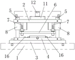
FIG. 1 is a schematic view showing the construction of the mold frame of the present invention;
FIG. 2 is a left side view of the mold frame of the present invention;
FIG. 3 is a schematic view of the structure of the trimming die of the present invention;
description of reference numerals: 1-lower template, 2-upper template, 3-cushion block, 4-female die limiting block, 5-first guide pillar component, 6-stripper, 7-second guide pillar component, 8-cylinder, 9-sensor, 10-air pipe joint, 11-backing plate, 12-guide block, 13-trimming punch, 14-stripper press plate, 15-trimming female die and 16-fixing screw.
Detailed Description
The following further describes embodiments of the present invention with reference to the drawings. It should be noted that the description of the embodiments is provided to help understanding of the present invention, but the present invention is not limited thereto. In addition, the technical features involved in the embodiments of the present invention described below may be combined with each other as long as they do not conflict with each other.
Referring to fig. 1-3, the present invention provides an automatic mechanical trimming die set for an aviation precision forging blade, comprising: the die carrier comprises a lower die plate 1 and an upper die plate 2, wherein a cushion block 3 is fixedly arranged on the lower die plate 1, a female die limiting block 4 is fixedly arranged on the cushion block 3, one side of the lower die plate 1 and one side of the upper die plate 2 are fixedly connected through a first guide pillar assembly 5, four first guide pillar assemblies 5 are arranged, one ends of the four first guide pillar assemblies 5 are respectively and fixedly connected with the upper die plate 2, one ends of the four first guide pillar assemblies 5 are respectively and fixedly connected with the lower die plate 1, a discharging plate 6 is arranged between the upper die plate 2 and the female die limiting block 4, the discharging plate 6 is fixedly connected with the upper die plate 2 through a second guide pillar assembly 7, four second guide pillar assemblies 7 are arranged, one ends of the four second guide pillar assemblies 7 are respectively and fixedly connected with the upper die plate 2, and the other ends of the four second guide pillar assemblies 7 are respectively and fixedly connected with the discharging plate 6, two ends of the stripper plate 6 are respectively connected with an air cylinder 8, and the air cylinders 8 are respectively connected with a sensor 9 and an air pipe joint 10; a backing plate 11 is arranged on the other side of the upper template 2, a guide block 12 is arranged on the backing plate 11, the backing plate 11 is fixed between the upper template 2 and the equipment by using screws and pins, and the guide pins 12 play a role in guiding the die carrier; the trimming die consists of a trimming punch 13, a discharging press plate 14 and a trimming female die 15; the trimming punch 13 is fixedly connected with the upper die plate 2, the trimming punch 13 is fixed on the upper die plate through a pin and a screw, the discharging press plate 14 is fixedly connected with the discharging plate 6, the trimming female die 15 is correspondingly fixed in the female die limiting block 4, and the trimming punch 13 is correspondingly arranged with the discharging press plate 14 and the trimming female die 15. The profile structure of the finish forging blade is complex, the requirement on the size precision is high, the design of the trimming die is considered as important, but the precision guarantee of the trimming die frame is more critical. The trimming die punch is fixed on the trimming die upper die plate 2 through the screws and the pins, the pins can be fixed well to play a role in guiding and positioning, the punch can be effectively fixed, the working consistency and precision of the punch are guaranteed, the female die limiting block 4 is provided with the fixing screws 16, the trimming female die 15 is fixedly clamped in the female die limiting block 4 through the fixing screws 16, the position of the female die can be adjusted through screwing the screws around the female die limiting block 4, the working fit clearance between the punch and the female die is guaranteed to be different from 0.05mm to 0.20mm, and the trimming clearance can be actually controlled according to the size of a blade and the thickness of a flash. The discharging pressing plate is fixed on the discharging plate 6 through screws, the discharging plate 6 is connected with the two ultrathin cylinders 8, and the discharging plate 6 can complete the flash discharging action along with the work of the cylinders 8 during trimming. The device makes through die carrier and side cut mould side cut drift 13 with side cut female die 15 precision fit realizes the good mechanical side cut of size uniformity's behind the side cut technology to through sensor 9 and cylinder 8's connection and realize the automatic purpose of producing according to the beat, the calendering before the side cut has reduced the size deformation of side cut, unloads the overlap automatically after the side cut, very big improvement side cut efficiency, and have advantages such as high accuracy, simple operation.
The technical principle is as follows: the die carrier is installed on the workstation of punch press, and cope match-plate pattern 2 is installed on punch press owner's slider, and trimming die drift 13 is installed on cope match-plate pattern 2, and the up-and-down motion of punch press slider drive cope match-plate pattern 2 and trimming die drift 13, and side cut bed die 15 is installed in bed die stopper 4, and the clamp plate 14 of unloading is installed on stripper 6. During work debugging, the trimming punch 13 is fastened on the upper die plate 2 through a screw and a positioning pin, the discharging press plate 14 is fastened in a clamping groove of the discharging plate 6 through a screw, the female die is placed in the limiting block, the trimming punch 13 slowly falls down to adjust the relative positions of the trimming female die 15 and the trimming punch 13, the trimming punch 13 falls into the trimming female die 15 to screw up eight fixing screws 16 around the female die limiting block 4 when the clearance is just suitable, and the trimming die is mounted. When the trimming operation is carried out, the punch press sliding block drives the trimming punch 13 to the upper limit top point position, a workpiece is clamped and placed on the trimming female die 15 through a robot, the two cylinders 8 are opened, and the discharging plate 6 and the discharging pressing plate 14 are arranged below the workpiece; the main sliding block of the punch press drives the trimming punch 13 and the discharging pressing plate 14 on the upper template to move downwards, and the discharging pressing plate 14 contacts the workpiece first to press the flash of the blade; at the moment, after the sensor 9 receives a signal, the cylinder 8 is closed, the discharging plate 6 drives the discharging pressure plate 14 to ascend, the trimming punch 13 enters the trimming female die 15, the blade flashes are cut off by the cutting edge, the workpiece falls on a sliding rail below the punch press and enters a material box, and the flashes are hung on the trimming punch 13; when the main sliding block of the punch rises to the upper limit vertex position, the punch drives the flash hung on the punch to rise, at the moment, the material tray connected with the flash enters the lower part of the punch, the sensor 9 outputs a signal, the cylinder 8 is opened to drive the pressing plate to unload the flash, the material tray connected with the flash is moved out of the die carrier, and the trimming process is finished. The process that the robot clamps and places the trimming female die 15, the main sliding block of the punch press drives the trimming punch 13 and the discharging press plate 14 on the upper die plate 2 to move downwards, and the discharging press plate 14 contacts the workpiece first to press the flash of the blade; after the sensor 9 receives a signal, the cylinder 8 is closed, the discharging plate 6 drives the discharging pressure plate 14 to ascend, the trimming punch 13 enters the trimming female die 15, the blade flashes are cut off by the cutting edge, a workpiece falls on a sliding rail below the punch press and enters a material box, and the flashes are hung on the trimming punch 13; when a main sliding block of the punch rises to an upper limit vertex position, the punch drives the flash hung on the punch to rise, at the moment, the material tray connected with the flash enters the lower part of the punch, the sensor 9 outputs a signal, the cylinder 8 is opened to drive the pressing plate to unload the flash, and the material tray connected with the flash is moved out of the die carrier.
Preferably, the working fit clearance between the trimming punch 13 and the trimming female die 15 is 0.05 mm-0.20 mm, and the trimming clearance can be actually controlled according to the size of the blade and the thickness of the flash.
Preferably, the discharging pressure plate 14 is fixed on the discharging plate 6 through screws, and the screws are connected to facilitate disassembly.
Preferably, the trimming punch 13 is fixed on the upper die plate 2 by screws, and the screws are connected to facilitate disassembly.
Preferably, the two air cylinders 8 are respectively and fixedly connected with the upper template 2 and used for fixing the air cylinders 8 and preventing the air cylinders 8 from moving.
The embodiments of the present invention have been described in detail with reference to the accompanying drawings, but the present invention is not limited to the described embodiments. It will be apparent to those skilled in the art that various changes, modifications, substitutions and alterations can be made in these embodiments without departing from the principles and spirit of the invention, and the scope of protection is still within the scope of the invention.
Claims (8)
1. The utility model provides an automatic mechanical side cut die carrier of aviation finish forge blade which characterized in that includes: the die carrier comprises a lower template (1) and an upper template (2), a cushion block (3) is fixedly arranged on the lower template (1), a female die limiting block (4) is fixedly arranged on the cushion block (3), the lower template (1) is fixedly connected with one side of the upper template (2) through a first guide pillar assembly (5), a discharging plate (6) is arranged between the upper template (2) and the female die limiting block (4), the discharging plate (6) is fixedly connected with the upper template (2) through a second guide pillar assembly (7), two ends of the discharging plate (6) are respectively connected with an air cylinder (8), and the air cylinder (8) is respectively connected with a sensor (9) and an air pipe joint (10); a backing plate (11) is arranged on the other side of the upper template (2), and a guide block (12) is arranged on the backing plate (11); the trimming die consists of a trimming punch (13), a discharging pressure plate (14) and a trimming female die (15); side cut drift (13) with cope match-plate pattern (2) fixed connection, unload clamp plate (14) with stripper (6) fixed connection, what side cut bed die (15) suited fixes in bed die stopper (4), side cut drift (13) unload clamp plate (14) with side cut bed die (15) suit the setting.
2. The automatic mechanical trimming die carrier for the aviation precision forging blade as claimed in claim 1, wherein: the number of the first guide pillar assemblies (5) is four, one ends of the four first guide pillar assemblies (5) are fixedly connected with the upper template (2) respectively, and one ends of the four first guide pillar assemblies (5) are fixedly connected with the lower template (1) respectively.
3. The automatic mechanical trimming die carrier for the aviation precision forging blade as claimed in claim 1, wherein: and the female die limiting block (4) is provided with a fixing screw (16), and the trimming female die (15) is fixedly clamped in the female die limiting block (4) through the fixing screw (16).
4. The automatic mechanical trimming die carrier for the aviation precision forging blade as claimed in claim 1, wherein: the working fit clearance between the trimming punch (13) and the trimming female die (15) is 0.05-0.20 mm.
5. The automatic mechanical trimming die carrier for the aviation precision forging blade as claimed in claim 1, wherein: the number of the second guide pillar assemblies (7) is four, one ends of the four second guide pillar assemblies (7) are fixedly connected with the upper template (2) respectively, and the other ends of the four second guide pillar assemblies (7) are fixedly connected with the stripper plate (6) respectively.
6. The automatic mechanical trimming die carrier for the aviation precision forging blade as claimed in claim 1, wherein: the discharging pressing plate (14) is fixed on the discharging plate (6) through screws.
7. The automatic mechanical trimming die carrier for the aviation precision forging blade as claimed in claim 1, wherein: the trimming punch (13) is fixed on the upper template (2) through screws.
8. The automatic mechanical trimming die carrier for the aviation precision forging blade as claimed in claim 1, wherein: the two air cylinders (8) are respectively and fixedly connected with the upper template (2).
Priority Applications (1)
| Application Number | Priority Date | Filing Date | Title |
|---|---|---|---|
| CN202210022212.4A CN114346054B (en) | 2022-01-10 | 2022-01-10 | Automatic mechanical trimming die carrier for aviation precision forging blade |
Applications Claiming Priority (1)
| Application Number | Priority Date | Filing Date | Title |
|---|---|---|---|
| CN202210022212.4A CN114346054B (en) | 2022-01-10 | 2022-01-10 | Automatic mechanical trimming die carrier for aviation precision forging blade |
Publications (2)
| Publication Number | Publication Date |
|---|---|
| CN114346054A true CN114346054A (en) | 2022-04-15 |
| CN114346054B CN114346054B (en) | 2023-09-01 |
Family
ID=81109470
Family Applications (1)
| Application Number | Title | Priority Date | Filing Date |
|---|---|---|---|
| CN202210022212.4A Active CN114346054B (en) | 2022-01-10 | 2022-01-10 | Automatic mechanical trimming die carrier for aviation precision forging blade |
Country Status (1)
| Country | Link |
|---|---|
| CN (1) | CN114346054B (en) |
Cited By (2)
| Publication number | Priority date | Publication date | Assignee | Title |
|---|---|---|---|---|
| CN114850370A (en) * | 2022-05-23 | 2022-08-05 | 山东豪迈精锻科技有限公司 | Automatic separation device for trimming flash of caterpillar track section |
| CN116078898A (en) * | 2022-12-05 | 2023-05-09 | 马鞍山市恒特重工科技有限公司 | Stamping structure for producing and processing wear-resistant corrosion-resistant heat-resistant parts |
Citations (6)
| Publication number | Priority date | Publication date | Assignee | Title |
|---|---|---|---|---|
| JP2002143956A (en) * | 2000-11-06 | 2002-05-21 | Seiko Epson Corp | Press slug remover, and operating method thereof |
| NL2009262C2 (en) * | 2012-08-01 | 2014-02-04 | Trioliet Holding B V | DEVICE FOR DISMANTLING FEED. |
| CN204799865U (en) * | 2015-07-17 | 2015-11-25 | 西安航空动力股份有限公司 | Modular finish forge blade side cut mould |
| CN208772253U (en) * | 2018-08-09 | 2019-04-23 | 南通恒利洋金属制品有限公司 | A kind of metal product shaving die |
| CN212042205U (en) * | 2020-03-09 | 2020-12-01 | 重庆大江杰信锻造有限公司 | Novel forge hook tail frame framework trimming mechanism |
| CN215144357U (en) * | 2021-04-29 | 2021-12-14 | 希西维轴承(盱眙)有限公司 | Precision forging stamping die |
-
2022
- 2022-01-10 CN CN202210022212.4A patent/CN114346054B/en active Active
Patent Citations (6)
| Publication number | Priority date | Publication date | Assignee | Title |
|---|---|---|---|---|
| JP2002143956A (en) * | 2000-11-06 | 2002-05-21 | Seiko Epson Corp | Press slug remover, and operating method thereof |
| NL2009262C2 (en) * | 2012-08-01 | 2014-02-04 | Trioliet Holding B V | DEVICE FOR DISMANTLING FEED. |
| CN204799865U (en) * | 2015-07-17 | 2015-11-25 | 西安航空动力股份有限公司 | Modular finish forge blade side cut mould |
| CN208772253U (en) * | 2018-08-09 | 2019-04-23 | 南通恒利洋金属制品有限公司 | A kind of metal product shaving die |
| CN212042205U (en) * | 2020-03-09 | 2020-12-01 | 重庆大江杰信锻造有限公司 | Novel forge hook tail frame framework trimming mechanism |
| CN215144357U (en) * | 2021-04-29 | 2021-12-14 | 希西维轴承(盱眙)有限公司 | Precision forging stamping die |
Cited By (2)
| Publication number | Priority date | Publication date | Assignee | Title |
|---|---|---|---|---|
| CN114850370A (en) * | 2022-05-23 | 2022-08-05 | 山东豪迈精锻科技有限公司 | Automatic separation device for trimming flash of caterpillar track section |
| CN116078898A (en) * | 2022-12-05 | 2023-05-09 | 马鞍山市恒特重工科技有限公司 | Stamping structure for producing and processing wear-resistant corrosion-resistant heat-resistant parts |
Also Published As
| Publication number | Publication date |
|---|---|
| CN114346054B (en) | 2023-09-01 |
Similar Documents
| Publication | Publication Date | Title |
|---|---|---|
| CN114346054A (en) | Automatic mechanical trimming die carrier for aviation precision forging blade | |
| CN1321785C (en) | Apparatus for blanking and processing profile notches of rubber sealing strip | |
| CN212070018U (en) | High-precision bending device for hardware machining | |
| CN206810957U (en) | Two face floating punching dies | |
| CN212944887U (en) | Modular punching die frame | |
| CN210450914U (en) | Improved pouring clamp special for precision forging blade | |
| CN110252999B (en) | Improved casting clamp special for precisely-forged blade | |
| CN111360163B (en) | Bending die for processing annular workpiece | |
| CN211516665U (en) | Stamping system for air outlet flange assembly | |
| CN210451855U (en) | Quick workpiece clamping device | |
| CN107442645B (en) | Automobile top cover floating cavity die punching die | |
| CN205587512U (en) | Progressive forward of numerical control takes shape and uses fixture device | |
| CN218193791U (en) | Milling machine fixture for processing curved surface mould pressing piece | |
| CN110936133A (en) | Flexible multi-pressure-head press-mounting device | |
| CN220698049U (en) | Inclined plane accurate side turning mechanism | |
| CN211758010U (en) | Quick forming die of turn-ups mounting | |
| CN212397827U (en) | Composite forming structure in progressive die | |
| CN1203935C (en) | Intensifying fabricating methods for finishing operation of parts | |
| CN219853129U (en) | Large R angle forming and processing device for metal parts on engineering machinery cab | |
| CN215918854U (en) | Mould positioning device for automobile covering part | |
| CN216541939U (en) | Disposable machining forming device for thin-wall thick section | |
| CN219357887U (en) | Automatic hot pressing device for producing automobile engine connecting rod | |
| CN210125681U (en) | Make things convenient for front groove forming die of height adjustment | |
| RU2776751C1 (en) | Stamp for extrusion on a two-axis press | |
| CN219130528U (en) | Digital stamping die capable of rapidly demolding |
Legal Events
| Date | Code | Title | Description |
|---|---|---|---|
| PB01 | Publication | ||
| PB01 | Publication | ||
| SE01 | Entry into force of request for substantive examination | ||
| SE01 | Entry into force of request for substantive examination | ||
| GR01 | Patent grant | ||
| GR01 | Patent grant |