CN114345197A - High-efficient agitating unit of aviation fuel oil - Google Patents
High-efficient agitating unit of aviation fuel oil Download PDFInfo
- Publication number
- CN114345197A CN114345197A CN202210062946.5A CN202210062946A CN114345197A CN 114345197 A CN114345197 A CN 114345197A CN 202210062946 A CN202210062946 A CN 202210062946A CN 114345197 A CN114345197 A CN 114345197A
- Authority
- CN
- China
- Prior art keywords
- rotating
- ring
- bevel gear
- fixedly connected
- gear
- Prior art date
- Legal status (The legal status is an assumption and is not a legal conclusion. Google has not performed a legal analysis and makes no representation as to the accuracy of the status listed.)
- Pending
Links
Images


Abstract
The invention provides an efficient aviation fuel oil stirring device, belongs to the technical field of aviation fuel production, and effectively solves the problems that an additive and fuel are not uniformly stirred, the efficiency is low, and precipitates are easy to generate in the aviation fuel production process. This technical scheme includes a high-efficient agitating unit of aviation fuel oil, including the agitator, be provided with interior swivel mount and outer swivel mount in the agitator, interior swivel mount and outer swivel mount are connected with actuating mechanism, and interior swivel mount and outer swivel mount all are provided with main stirring vane, and the agitator is inside to be communicated with the output of additive pipe, and the below that is close to additive pipe output is provided with rabbling mechanism in advance, and rabbling mechanism sets up on interior swivel mount in advance and rotatory with the cooperation of interior swivel mount. The invention has the beneficial effects that: provides a stirring device which can efficiently and fully stir aviation fuel and additives to prevent the generation of sediments.
Description
Technical Field
The invention relates to the technical field of aviation fuel production, in particular to a high-efficiency stirring device for aviation fuel oil.
Background
In the production process of aviation fuel oil, fuel mixed additives are required, in the process of adding the additives, lubricating oil is required to be stirred, the currently adopted mode is that the additives are added into fuel from the upper part of a stirring device and stirred, and the stirring process often has the defects of uneven stirring, slow stirring speed, partial precipitates, inconvenient cleaning and influence on the quality of the aviation fuel oil.
Therefore, how to solve the above technical problems becomes the subject of the present invention.
Disclosure of Invention
In order to solve the defects of the prior art, the invention provides a stirring device which can efficiently and fully stir aviation fuel and additives to prevent precipitates from being generated.
The technical scheme adopted by the invention for solving the technical problems is as follows: the invention provides an efficient aviation fuel oil stirring device which comprises a stirring barrel, wherein the top and the bottom of the stirring barrel are respectively provided with an oil inlet and an oil outlet, and the stirring barrel is arranged above a base;
an inner rotating frame and an outer rotating frame are arranged in the stirring barrel, and the inner rotating frame and the outer rotating frame are connected with a driving mechanism;
the rotating directions of the inner rotating frame and the outer rotating frame are opposite and are mutually and automatically switched in a staged manner, and the inner rotating frame and the outer rotating frame are both provided with main stirring blades;
the inside output intercommunication with the additive pipe of agitator, be close to the below of additive pipe output is provided with rabbling mechanism in advance, rabbling mechanism set up in advance on the internal rotating frame and with the cooperation of internal rotating frame is rotatory.
A central column which is superposed with the central axis of the stirring barrel and penetrates through the inner side and the outer side of the stirring barrel is arranged in the central part of the stirring barrel, and the outer rotating frame and the inner rotating frame are respectively matched with the central column in a rotating manner from top to bottom in the stirring barrel;
the outer rotating frame comprises an upper rotating ring which is coaxially sleeved on the outer side of the central column and is rotatably connected with the central column, the outer side of the upper rotating ring is uniformly and fixedly connected with a plurality of horizontally arranged upper cross rods along the radial direction, the bottom of one end, far away from the upper rotating ring, of each upper cross rod is rotatably connected with an outer rotating rod which faces downwards vertically, and a plurality of main stirring blades are uniformly and coaxially sleeved on the outer side of each outer rotating rod from top to bottom;
the inner rotating frame comprises a lower rotating ring which is coaxially sleeved on the outer side of the central column and is rotatably connected with the central column, the lower rotating ring is positioned below the upper rotating ring, the outer side of the lower rotating ring is uniformly and fixedly connected with a plurality of horizontally arranged lower cross rods along the radial direction, the bottom of one end, away from the lower rotating ring, of each lower cross rod is rotatably connected with an inner rotating rod which faces vertically downwards, and the outer side of each inner rotating rod is uniformly and coaxially sleeved with a plurality of main stirring blades from top to bottom;
the outer rotating rod is close to the inner wall of the stirring barrel, and the inner rotating rod is close to the central part of the stirring barrel.
The driving mechanism comprises a first bevel gear which is coaxially and fixedly connected to the bottom of the upper rotating ring and faces downwards and a second bevel gear which is coaxially and fixedly connected to the top of the lower rotating ring and faces upwards;
the central part of the central column between the first bevel gear and the second bevel gear is fixedly connected with a connecting rod which penetrates through two sides of the central column, the central axis of the connecting rod is vertical to the central axis of the central column, two ends of the connecting rod are respectively coaxially and rotatably connected with a third bevel gear and a fourth bevel gear which are oppositely arranged, and the upper side and the lower side of the third bevel gear and the upper side and the lower side of the fourth bevel gear are respectively and simultaneously meshed with the first bevel gear and the second bevel gear;
the top of the upper rotating ring is coaxially and fixedly connected with a driving ring, the driving ring is positioned above the stirring barrel and sleeved outside the central column, the outside of the top of the driving ring is coaxially sleeved with a driving gear, and the driving gear is connected with a power component.
The power component comprises an L-shaped rotating frame which is arranged above the driving gear and is in rotating fit with the central column, a rack is connected to the rotating frame in a sliding mode, and the rack is meshed with the driving gear;
one end of the rack is hinged with one end of a pulling rod, the other end, far away from the hinged end, of the pulling rod is provided with a lantern ring, the lantern ring is coaxially sleeved on the outer side of a vertically arranged stand column, the top of the stand column is rotatably connected to the bottom of a mounting plate arranged above the top of the stirring barrel, and the outer side of the stand column is coaxially sleeved with a first transmission disc;
the top of agitator is provided with driving motor, the coaxial fixedly connected with second transmission dish of driving motor output shaft, the second transmission dish with the cover is equipped with first drive belt between the first transmission dish.
An additive tank is arranged at the top of the stirring barrel and is communicated with an additive delivery pump, and the output end of the additive delivery pump is communicated with the input end of the additive conduit;
the drive motor is characterized in that a third drive disc is coaxially and fixedly connected with a drive rotating shaft of the agent delivery pump, a fourth drive disc is coaxially and fixedly connected with an output shaft of the drive motor, and a second drive belt is sleeved between the third drive disc and the fourth drive disc.
The additive conduit penetrates from the center of the top of the central column and penetrates below the lower rotating ring;
the pre-stirring mechanism comprises a first circular ring horizontally arranged below the output end of the additive guide pipe, the outer wall of the first circular ring is fixedly connected with the bottom of the lower rotating ring, a rotating sleeve is coaxially arranged at the center of the first circular ring, and a plurality of upper blades are uniformly and fixedly connected between the outer wall of the rotating sleeve and the inner wall of the first circular ring;
a second circular ring is coaxially arranged below the first circular ring, the rotating sleeve is rotatably connected with a rotating shaft facing downwards, and a plurality of lower blades are uniformly and fixedly connected between the bottom side of the rotating shaft and the inner wall of the second circular ring along the circumferential direction;
the outer side of the second circular ring is uniformly provided with a plurality of outer tooth blocks, the outer side of each inner rotating rod is sleeved with a first gear at the same height, and the outer tooth blocks are meshed with the first gears.
The bottom of the inner rotating rod is coaxially and fixedly connected with a second gear, and the bottom of the outer rotating rod is coaxially and fixedly connected with a third gear;
the agitator bottom is provided with cyclic annular inner rail and the outer rail of the same centre of a circle respectively, the inner rail with the outer rail inner wall all along the even a plurality of interior cogs that are provided with of ring direction, the second gear with on the inner rail interior cogs meshing, the third gear with on the outer rail interior cogs meshing.
An installation cylinder is rotatably connected between the upper rotating ring and the lower rotating ring, and the first bevel gear, the second bevel gear, the third bevel gear and the fourth bevel gear are both positioned in the installation cylinder.
And the output end of the additive guide pipe is provided with a horn-shaped spray head with a downward large opening.
When the invention is actually used: firstly, adding fuel oil into a stirring barrel through an oil inlet, adding an additive into an additive box, starting a driving motor, driving a first driving disc to rotate through a first driving belt, driving a pulling rod to rotate through the first driving disc, pulling a rack hinged with the pulling rod through the pulling rod, driving a driving gear to rotate through the rack, driving the driving gear to rotate anticlockwise through the rack when the pulling rod is pulled to one side far away from the driving gear, driving the driving gear to clockwise move through the rack when the pulling rod moves from a farthest point to one side of the driving gear, repeating the cycle, driving an outer rotating frame to synchronously rotate in the same direction through the driving gear, simultaneously driving a second bevel gear to rotate in the opposite direction through a third bevel gear and a fourth bevel gear, driving the inner rotating frame and the outer rotating frame to rotate in the opposite direction through the second bevel gear, and enabling an inner rotating rod to drive main stirring blades connected with the inner rotating frame to rotate in the opposite direction through the inner rotating frame under the matching of the second gear and an inner rail, under the coordination of the third gear and the outer rail, the outer rotating rod drives the main stirring blade connected with the outer rotating rod to rotate in the direction opposite to the rotating direction of the outer rotating frame, and the rotating direction is automatically switched along with the change of the rotating directions of the inner rotating frame and the outer rotating frame.
Drive the fourth transmission dish simultaneously after the driving motor starts and rotate and drive the inside center department that defeated agent pump pours the additive into the agitator with certain pressure through second drive belt and third transmission dish, the additive at first carries out preliminary mixing by rabbling mechanism in advance, the additive after the preliminary mixing continues to be stirred in order to reach good stirring effect by main stirring vane, prevents that the precipitate from producing, opens oil-out valve discharge after the stirring is accomplished, rabbling mechanism's working process in advance: the lower rotating ring drives the first circular ring to rotate, the first circular ring drives the upper blade to rotate, the first gear rotates under the driving of the rotation of the inner rotating rod, and the gear block which is meshed with the outer part of the second circular ring drives the second circular ring to rotate, so that the lower blade is driven to rotate to stir.
The invention has the beneficial effects that:
1. the additive and the aviation fuel can be efficiently and quickly stirred, the stirring is sufficient and uniform, the generation of precipitates is avoided, and the production quality of the aviation fuel is ensured;
2. the inner rotating frame and the outer rotating frame respectively drive the main stirring blades to rotate in opposite directions and repeatedly switch back and forth, so that the full and effective stirring process can be ensured;
3. according to the invention, the additive is injected into the fuel at a certain pressure instead of being placed on the top surface of the fuel for stirring, the pre-stirring mechanism is arranged to perform local stirring when the additive just enters the fuel, and the stirring efficiency and the stirring effect are further accelerated by utilizing the rapid dispersion and fusion of the additive;
4. the invention has reasonable structural design, the power of the main stirring blade and the pre-stirring mechanism is derived from the driving motor and is skillfully matched through the structure, thereby not only saving the cost investment of the device, but also ensuring the consistency and the coordination of the overall operation of the equipment.
Drawings
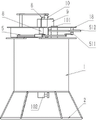
FIG. 1 is a front view of the present invention.
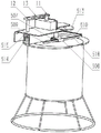
Fig. 2 is a schematic perspective view of the present invention.
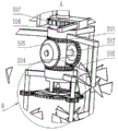
Fig. 3 is a front view of the inside of the mixing tank of the present invention.
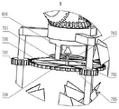
Fig. 4 is a schematic view of the internal three-dimensional structure of the mixing tank of the present invention.
Fig. 5 is an enlarged view of the area a in fig. 4.
Fig. 6 is an enlarged view of the area B of fig. 5.
Wherein the reference numerals are: 1. a stirring barrel; 101. an oil inlet; 102. an oil outlet; 2. a base; 3. an inner rotating frame; 301. a lower swivel; 302. a lower cross bar; 303. an inner rotating rod; 304. a second gear; 4. an outer rotating frame; 401. an upper swivel; 402. an upper cross bar; 403. an outer rotating rod; 404. a third gear; 5. a drive mechanism; 501. a first bevel gear; 502. a second bevel gear; 503. a connecting rod; 504. a third bevel gear; 505. A fourth bevel gear; 506. a drive ring; 507. a drive gear; 508. a rotating frame; 509. a rack; 510. pulling a rod; 511. a collar; 512. a column; 513. a first drive disk; 514. a drive motor; 515. a second drive disk; 516. a first drive belt; 6. an additive conduit; 601. a spray head; 7. a pre-stirring mechanism; 701. a first circular ring; 702. rotating the sleeve; 703. an upper blade; 704. a second circular ring; 705. a rotating shaft; 706. a lower blade; 707. a first gear; 8. A central column; 9. an additive tank; 10. a delivery pump; 11. a third rotating disk; 12. a fourth drive disk; 13. a second belt; 14. an inner rail; 15. an outer rail; 16. mounting the cylinder; 17. a main stirring blade; 18. and (7) mounting the plate.
Detailed Description
In order to clearly illustrate the technical features of the present solution, the present solution is explained below by way of specific embodiments.
Referring to fig. 1 to 6, the invention discloses a high-efficiency stirring device for aviation fuel oil, which is characterized by comprising a stirring barrel 1, wherein the top and the bottom of the stirring barrel 1 are respectively provided with an oil inlet 101 and an oil outlet 102, the stirring barrel 1 is arranged above a base 2, an inner rotating frame 3 and an outer rotating frame 4 are arranged in the stirring barrel 1, the inner rotating frame 3 and the outer rotating frame 4 are connected with a driving mechanism 5, the rotating directions of the inner rotating frame 3 and the outer rotating frame 4 are opposite and are mutually and automatically switched in a staged manner, the inner rotating frame 3 and the outer rotating frame 4 are both provided with main stirring blades 17, the inner part of the stirring barrel 1 is communicated with the output end of an additive conduit 6, a pre-stirring mechanism 7 is arranged below the output end of the additive conduit 6, and the pre-stirring mechanism 7 is arranged on the inner rotating frame 3 and rotates in a manner matched with the inner rotating frame 3.
The central part of the stirring barrel 1 is provided with a central column 8 which is superposed with the central axis of the stirring barrel 1 and penetrates through the inner side and the outer side of the stirring barrel 1, the central column 8 is positioned in the stirring barrel 1, the inner part of the central column is respectively matched with an outer rotating frame 4 and an inner rotating frame 3 in a rotating way from top to bottom, the outer rotating frame 4 comprises an upper rotating ring 401 which is coaxially sleeved outside the central column 8 and is rotationally connected with the central column, the outer side of the upper rotating ring 401 is uniformly and fixedly connected with a plurality of upper cross rods 402 which are horizontally arranged along the radial direction, the bottom of one end of each upper cross rod 402 far away from the upper rotating ring 401 is rotationally connected with an outer rotating rod 403 which faces downwards vertically, the outer side of each outer rotating rod 403 is uniformly and coaxially sleeved with a plurality of main stirring blades 17 from top to bottom, the inner rotating frame 3 comprises a lower rotating ring 301 which is coaxially sleeved outside the central column 8 and is rotationally connected with the same, the lower rotating ring 301 is positioned below the upper rotating ring 401, the outer side of the lower rotating ring 301 is uniformly and fixedly connected with a plurality of lower cross rods 302 which are horizontally arranged along the radial direction, every bottom end 302 is kept away from lower swivel 301 one end bottom and all is rotated and is connected with vertical interior bull stick 303 down, and the outside of every interior bull stick 303 from top to bottom even coaxial cup joints a plurality of main stirring vane 17, and outer bull stick 403 is close to the inner wall of agitator 1, and interior bull stick 303 is close to the central part of agitator 1. The coaxial fixedly connected with second gear 304 in interior bull 303 bottom, the equal coaxial fixedly connected with third gear 404 in outer bull 403 bottom, agitator 1 bottom is provided with annular inner rail 14 and outer rail 15 of concentric circles respectively, inner rail 14 and outer rail 15 inner wall all along the even a plurality of interior toothblocks that are provided with of ring direction, second gear 304 meshes with the interior toothblock on the inner rail 14, third gear 404 meshes with the interior toothblock on the outer rail 15.
The driving mechanism 5 comprises a first bevel gear 501 coaxially and fixedly connected to the bottom of the upper rotating ring 401 and facing downwards and a second bevel gear 502 coaxially and fixedly connected to the top of the lower rotating ring 301 and facing upwards, the central part of the central column 8 between the first bevel gear 501 and the second bevel gear 502 is fixedly connected with a connecting rod 503 penetrating through two sides of the central column 8, the central axis of the connecting rod 503 is perpendicular to the central axis of the central column 8, two ends of the connecting rod 503 are respectively and coaxially and rotatably connected with a third bevel gear 504 and a fourth bevel gear 505 which are oppositely arranged, the upper side and the lower side of the third bevel gear 504 and the fourth bevel gear 505 are respectively and simultaneously meshed with the first bevel gear 501 and the second bevel gear 502, the top of the upper rotating ring 401 is coaxially and fixedly connected with a driving ring 506, the driving ring 506 is positioned above the stirring barrel 1 and sleeved outside the central column 8, and the driving gear 507 is coaxially sleeved outside the top of the driving ring 506, the drive gear 507 is connected to a power unit. A mounting cylinder 16 is rotatably connected between the upper rotating ring 401 and the lower rotating ring 301, and a first bevel gear 501 and a second bevel gear 502, and a third bevel gear 504 and a fourth bevel gear 505 are all positioned in the mounting cylinder 16.
Power component is including setting up in drive gear 507 top and with 8 normal post rotation fit's L shape rotating turret 508, sliding connection has rack 509 on the rotating turret 508, rack 509 and drive gear 507 mesh, the one end of rack is articulated with the one end of pulling the pole, the other end that the hinged end was kept away from to the pulling pole is provided with the lantern ring, the lantern ring is coaxial to be cup jointed in the stand outside of vertical setting, the stand top is rotated and is connected in the bottom that sets up the mounting panel above the agitator top, the stand outside is coaxial to be cup jointed first drive disk, the top of agitator 1 is provided with driving motor 514, the coaxial fixedly connected with second transmission dish 515 of driving motor 514 output shaft, the cover is equipped with first drive belt 516 between second transmission dish 515 and the first drive disk 513.
An additive box 9 is arranged at the top of the stirring barrel 1, the additive box 9 is communicated with an additive delivery pump 10, the output end of the additive delivery pump 10 is communicated with the input end of the additive guide pipe 6, a third transmission disc 11 is coaxially and fixedly connected with a driving rotating shaft of the additive delivery pump 10, a fourth transmission disc 12 is coaxially and fixedly connected with an output shaft of a driving motor 514, and a second transmission belt 13 is sleeved between the third transmission disc 11 and the fourth transmission disc 12.
The additive conduit 6 penetrates from the center of the top of the central column 8 and penetrates to the lower part of the lower rotating ring 301 all the time, the pre-stirring mechanism 7 comprises a first circular ring 701 horizontally arranged below the output end of the additive conduit 6, the outer wall of the first circular ring 701 is fixedly connected with the bottom of the lower rotating ring 301, a rotating sleeve 702 is coaxially arranged at the center of the first circular ring 701, a plurality of upper blades 703 are uniformly and fixedly connected between the outer wall of the rotating sleeve 702 and the inner wall of the first circular ring 701, a second circular ring 704 is coaxially arranged below the first circular ring 701, the rotating sleeve 702 is rotatably connected with a rotating shaft 705 facing downwards, a plurality of lower blades 706 are uniformly and fixedly connected between the bottom side of the rotating shaft 705 and the inner wall of the second circular ring 704 along the circumferential direction, a plurality of outer tooth blocks are uniformly arranged on the outer side of the second circular ring 704, a first gear 707 is sleeved on the outer side of each inner rotating rod 303 at the same height, and the outer tooth blocks are meshed with the plurality of first gears 707. The output end of the additive conduit 6 is provided with a horn-shaped spray head 601 with a downward large opening.
When the invention is actually used: firstly, fuel oil is added into the stirring barrel 1 through the oil inlet 101, the additive is added into the additive tank 9, the driving motor 514 is started, the first driving disc 513 is driven to rotate through the first driving belt 516, the first driving disc 513 drives the pulling bar 510 to rotate, the pulling bar 510 pulls the rack 509 hinged with the pulling bar, the rack 509 drives the driving gear 507 to rotate, when the pulling bar 510 is pulled to the side far away from the driving gear 507, the rack 509 drives the driving gear 507 to rotate anticlockwise, when the pulling bar 510 moves to the driving gear 507 side from the farthest point, the rack 509 drives the driving gear 507 to move clockwise, so that the cycle is repeated, the driving gear 507 drives the external rotating frame 4 to synchronously rotate in the same direction, meanwhile, the first bevel gear 501 drives the second bevel gear 502 to rotate in the opposite direction through the third bevel gear 504 and the fourth bevel gear 505, and the second bevel gear 502 drives the internal rotating frame 3 and the external rotating frame 4 to rotate in the opposite direction, at the same time, the inner rotating rod 303 drives the main stirring blades 17 connected thereto to rotate in the direction opposite to the rotating direction of the inner rotating frame 3 by the cooperation of the second gear 304 and the inner rail 14, and the outer rotating rod 403 drives the main stirring blades 17 connected thereto to rotate in the direction opposite to the rotating direction of the outer rotating frame 4 by the cooperation of the third gear 404 and the outer rail 15, and the rotation direction is automatically switched according to the change of the rotating directions of the inner rotating frame 3 and the outer rotating frame 4.
After the driving motor 514 starts, it drives the fourth transmission disc 12 simultaneously and rotates and drives the internal center department that the additive pours into the agitator 1 into the additive with certain pressure through the second drive belt 13 and the third transmission disc 11, the additive is at first carried out preliminary mixing by the rabbling mechanism 7 in advance, the additive after preliminary mixing continues to be stirred by main stirring vane 17 in order to reach good stirring effect, prevent that the precipitate from producing, open oil-out 102 valve discharge after the stirring is accomplished, the working process of the rabbling mechanism 7 in advance: the lower rotating ring 301 drives the first circular ring 701 to rotate, the first circular ring 701 drives the upper blade 703 to rotate, the first gear is driven to rotate by the rotation of the rotating rod 303 in 707, and the second circular ring 704 is driven to rotate by meshing a gear block outside the second circular ring 704, namely, the lower blade 706 is driven to rotate for stirring.
The above description is only for the purpose of illustrating the preferred embodiments of the present invention and is not to be construed as limiting the invention, and any modifications, equivalents, improvements and the like that fall within the spirit and principle of the present invention are intended to be included therein.
Claims (9)
1. The high-efficiency stirring device for the aviation fuel oil is characterized by comprising a stirring barrel (1), wherein the top and the bottom of the stirring barrel (1) are respectively provided with an oil inlet (101) and an oil outlet (102), and the stirring barrel (1) is arranged above a base (2);
an inner rotating frame (3) and an outer rotating frame (4) are arranged in the stirring barrel (1), and the inner rotating frame (3) and the outer rotating frame (4) are connected with a driving mechanism (5);
the rotating directions of the inner rotating frame (3) and the outer rotating frame (4) are opposite and are mutually and automatically switched in a staged manner, and the inner rotating frame (3) and the outer rotating frame (4) are both provided with main stirring blades (17);
inside and the output intercommunication of additive pipe (6) of agitator (1), be close to the below of additive pipe (6) output is provided with rabbling mechanism (7) in advance, rabbling mechanism (7) in advance set up in on interior swivel mount (3) and with the cooperation of interior swivel mount (3) is rotatory.
2. The high-efficiency aviation fuel oil stirring device according to claim 1, wherein a central column (8) which is coincident with the central axis of the stirring barrel (1) and penetrates through the inner side and the outer side of the stirring barrel (1) is arranged in the central part of the stirring barrel (1), and the outer rotating frame (4) and the inner rotating frame (3) are respectively matched with the central column (8) in a rotating manner from top to bottom in the stirring barrel (1);
the outer rotating frame (4) comprises an upper rotating ring (401) which is coaxially sleeved on the outer side of the central column (8) and is rotatably connected with the central column, the outer side of the upper rotating ring (401) is uniformly and fixedly connected with a plurality of horizontally arranged upper cross rods (402) along the radial direction, the bottom of one end, away from the upper rotating ring (401), of each upper cross rod (402) is rotatably connected with an outer rotating rod (403) which faces downwards vertically, and the outer side of each outer rotating rod (403) is uniformly and coaxially sleeved with a plurality of main stirring blades (17) from top to bottom;
the inner rotating frame (3) comprises a lower rotating ring (301) which is coaxially sleeved on the outer side of the central column (8) and is rotatably connected with the central column, the lower rotating ring (301) is positioned below the upper rotating ring (401), the outer side of the lower rotating ring (301) is uniformly and fixedly connected with a plurality of horizontally arranged lower cross rods (302) along the radial direction, the bottom of one end, far away from the lower rotating ring (301), of each lower cross rod (302) is rotatably connected with an inner rotating rod (303) which faces downwards vertically, and the outer side of each inner rotating rod (303) is uniformly and coaxially sleeved with a plurality of main stirring blades (17) from top to bottom;
the outer rotating rod (403) is close to the inner wall of the stirring barrel (1), and the inner rotating rod (303) is close to the central part of the stirring barrel (1).
3. The high-efficiency aviation fuel oil stirring device as claimed in claim 2, wherein the driving mechanism (5) comprises a first bevel gear (501) coaxially and fixedly connected to the bottom of the upper rotating ring (401) and facing downwards and a second bevel gear (502) coaxially and fixedly connected to the top of the lower rotating ring (301) and facing upwards;
the central part of the central column (8) between the first bevel gear (501) and the second bevel gear (502) is fixedly connected with connecting rods (503) penetrating through two sides of the central column (8), the central axis of the connecting rods (503) is perpendicular to the central axis of the central column (8), two ends of each connecting rod (503) are respectively and coaxially and rotatably connected with a third bevel gear (504) and a fourth bevel gear (505) which are oppositely arranged, and the upper side and the lower side of each third bevel gear (504) and the upper side and the lower side of each fourth bevel gear (505) are respectively and simultaneously meshed with the first bevel gear (501) and the second bevel gear (502);
the top of the upper rotating ring (401) is coaxially and fixedly connected with a driving ring (506), the driving ring (506) is located above the stirring barrel (1) and sleeved on the outer side of the central column (8), the outer side of the top of the driving ring (506) is coaxially sleeved with a driving gear (507), and the driving gear (507) is connected with a power component.
4. The high-efficiency aviation fuel oil stirring device as recited in claim 3, wherein the power component comprises an L-shaped rotating frame (508) which is arranged above the driving gear (507) and is in rotating fit with the central column (8), a rack (509) is connected onto the rotating frame (508) in a sliding way, and the rack (509) is meshed with the driving gear (507);
one end of the rack (509) is hinged with one end of the pulling rod (510), the other end, far away from the hinged end, of the pulling rod (510) is provided with a lantern ring (511), the lantern ring (511) is coaxially sleeved on the outer side of a vertically arranged upright post (512), the top of the upright post (512) is rotatably connected to the bottom of a mounting plate (18) arranged above the top of the stirring barrel (1), and the outer side of the upright post (512) is coaxially sleeved with a first transmission disc (513);
the top of agitator (1) is provided with driving motor (514), the coaxial fixedly connected with second transmission dish (515) of driving motor (514) output shaft, second transmission dish (515) with the cover is equipped with first drive belt (516) between first transmission dish (513).
5. The high-efficiency aviation fuel oil stirring device according to claim 4, characterized in that an additive tank (9) is arranged at the top of the stirring barrel (1), the additive tank (9) is communicated with an additive delivery pump (10), and the output end of the additive delivery pump (10) is communicated with the input end of the additive conduit (6);
the drive shaft coaxial fixedly connected with third transmission dish (11) of defeated agent pump (10), the coaxial fixedly connected with fourth transmission dish (12) of driving motor (514) output shaft, third transmission dish (11) with the cover is equipped with second drive belt (13) between fourth transmission dish (12).
6. The high-efficiency aviation fuel oil stirring device as claimed in claim 5, wherein the additive conduit (6) penetrates from the center of the top of the central column (8) and penetrates to the position below the lower rotating ring (301);
the pre-stirring mechanism (7) comprises a first circular ring (701) horizontally arranged below the output end of the additive guide pipe (6), the outer wall of the first circular ring (701) is fixedly connected with the bottom of the lower rotating ring (301), a rotating sleeve (702) is coaxially arranged at the center of the first circular ring (701), and a plurality of upper blades (703) are uniformly and fixedly connected between the outer wall of the rotating sleeve (702) and the inner wall of the first circular ring (701);
a second circular ring (704) is coaxially arranged below the first circular ring (701), the rotating sleeve (702) is rotatably connected with a rotating shaft (705) which faces downwards, and a plurality of lower blades (706) are uniformly and fixedly connected between the bottom side of the rotating shaft (705) and the inner wall of the second circular ring (704) along the circumferential direction;
a plurality of outer tooth blocks are uniformly arranged on the outer side of the second circular ring (704), a first gear (707) is sleeved on the outer side of each inner rotating rod (303) at the same height, and the outer tooth blocks are meshed with the first gears (707).
7. The high-efficiency aviation fuel oil stirring device as claimed in claim 2, wherein a second gear (304) is coaxially and fixedly connected to the bottom of the inner rotating rod (303), and a third gear (404) is coaxially and fixedly connected to the bottom of the outer rotating rod (403);
the stirring barrel (1) bottom is provided with cyclic annular inner rail (14) and outer rail (15) of the same centre of a circle respectively, inner rail (14) with outer rail (15) inner wall all along the even a plurality of interior cogs that are provided with of ring direction, second gear (304) with on inner rail (14) interior cogs meshing, third gear (404) with on outer rail (15) interior cogs meshing.
8. The high-efficiency aviation fuel oil stirring device as claimed in claim 3, wherein a mounting cylinder (16) is rotatably connected between the upper rotating ring (401) and the lower rotating ring (301), and the first bevel gear (501) and the second bevel gear (502) and the third bevel gear (504) and the fourth bevel gear (505) are both located in the mounting cylinder (16).
9. The high-efficiency aviation fuel oil stirring device as claimed in claim 6, wherein the output end of the additive conduit (6) is provided with a horn-shaped nozzle (601) with a downward large opening.
Priority Applications (1)
| Application Number | Priority Date | Filing Date | Title |
|---|---|---|---|
| CN202210062946.5A CN114345197A (en) | 2022-01-20 | 2022-01-20 | High-efficient agitating unit of aviation fuel oil |
Applications Claiming Priority (1)
| Application Number | Priority Date | Filing Date | Title |
|---|---|---|---|
| CN202210062946.5A CN114345197A (en) | 2022-01-20 | 2022-01-20 | High-efficient agitating unit of aviation fuel oil |
Publications (1)
| Publication Number | Publication Date |
|---|---|
| CN114345197A true CN114345197A (en) | 2022-04-15 |
Family
ID=81091800
Family Applications (1)
| Application Number | Title | Priority Date | Filing Date |
|---|---|---|---|
| CN202210062946.5A Pending CN114345197A (en) | 2022-01-20 | 2022-01-20 | High-efficient agitating unit of aviation fuel oil |
Country Status (1)
| Country | Link |
|---|---|
| CN (1) | CN114345197A (en) |
Cited By (3)
| Publication number | Priority date | Publication date | Assignee | Title |
|---|---|---|---|---|
| CN114832679A (en) * | 2022-04-28 | 2022-08-02 | 江苏妙卫纸业有限公司 | Stirring equipment and application thereof in production of household paper |
| CN115282914A (en) * | 2022-08-12 | 2022-11-04 | 安徽匠星联创新材料科技有限公司 | Epoxy resin production process |
| CN115445499A (en) * | 2022-09-14 | 2022-12-09 | 浙江海正动物保健品有限公司 | Heat collection type constant temperature magnetic stirring bath with beaker fixing structure |
Citations (8)
| Publication number | Priority date | Publication date | Assignee | Title |
|---|---|---|---|---|
| CN106964279A (en) * | 2017-05-31 | 2017-07-21 | 山东新希望六和集团有限公司 | A kind of herding medicine agitating device and method |
| CN111482115A (en) * | 2020-04-29 | 2020-08-04 | 浙江李子园食品股份有限公司 | Milk mixing arrangement that can two-way reciprocal stirring |
| CN111888983A (en) * | 2020-08-11 | 2020-11-06 | 马鞍山金瓦格机械科技有限公司 | Mixed liquid stirring device for chemical production |
| WO2020255491A1 (en) * | 2019-06-20 | 2020-12-24 | 株式会社イズミフードマシナリ | Mixing blade assembly and mixing tank |
| CN213440385U (en) * | 2020-09-02 | 2021-06-15 | 芮明娟 | Material agitating unit is used in building engineering construction |
| CN214319924U (en) * | 2020-12-23 | 2021-10-01 | 福建省星源农牧科技股份有限公司 | Feed production is with mixing material device |
| CN215196609U (en) * | 2021-06-17 | 2021-12-17 | 商丘市永鼎生物科技有限公司 | Solid beverage raw material mixing device |
| CN215276926U (en) * | 2021-04-07 | 2021-12-24 | 杭州美利建印刷有限公司 | Ink mixing stirring device |
-
2022
- 2022-01-20 CN CN202210062946.5A patent/CN114345197A/en active Pending
Patent Citations (8)
| Publication number | Priority date | Publication date | Assignee | Title |
|---|---|---|---|---|
| CN106964279A (en) * | 2017-05-31 | 2017-07-21 | 山东新希望六和集团有限公司 | A kind of herding medicine agitating device and method |
| WO2020255491A1 (en) * | 2019-06-20 | 2020-12-24 | 株式会社イズミフードマシナリ | Mixing blade assembly and mixing tank |
| CN111482115A (en) * | 2020-04-29 | 2020-08-04 | 浙江李子园食品股份有限公司 | Milk mixing arrangement that can two-way reciprocal stirring |
| CN111888983A (en) * | 2020-08-11 | 2020-11-06 | 马鞍山金瓦格机械科技有限公司 | Mixed liquid stirring device for chemical production |
| CN213440385U (en) * | 2020-09-02 | 2021-06-15 | 芮明娟 | Material agitating unit is used in building engineering construction |
| CN214319924U (en) * | 2020-12-23 | 2021-10-01 | 福建省星源农牧科技股份有限公司 | Feed production is with mixing material device |
| CN215276926U (en) * | 2021-04-07 | 2021-12-24 | 杭州美利建印刷有限公司 | Ink mixing stirring device |
| CN215196609U (en) * | 2021-06-17 | 2021-12-17 | 商丘市永鼎生物科技有限公司 | Solid beverage raw material mixing device |
Cited By (4)
| Publication number | Priority date | Publication date | Assignee | Title |
|---|---|---|---|---|
| CN114832679A (en) * | 2022-04-28 | 2022-08-02 | 江苏妙卫纸业有限公司 | Stirring equipment and application thereof in production of household paper |
| CN115282914A (en) * | 2022-08-12 | 2022-11-04 | 安徽匠星联创新材料科技有限公司 | Epoxy resin production process |
| CN115445499A (en) * | 2022-09-14 | 2022-12-09 | 浙江海正动物保健品有限公司 | Heat collection type constant temperature magnetic stirring bath with beaker fixing structure |
| CN115445499B (en) * | 2022-09-14 | 2023-12-08 | 浙江海正动物保健品有限公司 | Heat collection type constant temperature magnetic stirring bath with beaker fixing structure |
Similar Documents
| Publication | Publication Date | Title |
|---|---|---|
| CN114345197A (en) | High-efficient agitating unit of aviation fuel oil | |
| CN211706616U (en) | Stirring device for processing compound food additive | |
| CN216964403U (en) | Anti-spilling stirring device for production of oilfield chemical additives | |
| CN113264705A (en) | Concrete water reducing agent and processing technology thereof | |
| CN211189967U (en) | Raw material mixing device is used in cosmetics production | |
| CN210356864U (en) | Lithium cell is mixer for raw materials processing convenient to liquid feeding | |
| CN216635110U (en) | Foam foaming machine convenient to dismantle clearance | |
| CN215586187U (en) | Proportioning device for production of medical liquid dressing | |
| CN115709031A (en) | Longxin oral liquid blending device with dispersing function | |
| CN215996632U (en) | Acylation reaction tank with heating and cooling functions | |
| CN213556610U (en) | Special spraying and mixing device for edible mushroom culture medium preparation | |
| CN213533174U (en) | Horizontal mixer is used in production of environmental protection concrete | |
| CN218962363U (en) | Lubricating oil blending device | |
| CN216879050U (en) | Agitating unit is used in production of nanometer aldehyde complexing agent that removes | |
| CN211754446U (en) | Glass water preparation equipment | |
| CN216024326U (en) | Blending and mixing kettle for injection production | |
| CN218422374U (en) | Breeding pig composite vitamin premix mixing device | |
| CN218962405U (en) | Coating mixing tank | |
| CN216704107U (en) | Conveyor is used in fire retardant production | |
| CN220609980U (en) | Oral cavity restoration material mixer capable of quantitatively discharging | |
| CN215901492U (en) | Metal powder coating production is with blending tank of misce bene | |
| CN219647215U (en) | Conductive agent production mixing equipment | |
| CN210705307U (en) | Concrete processing equipment | |
| CN220546848U (en) | Circulation mixing arrangement that petrochemical was used | |
| CN220802833U (en) | Electric automatization's agitating unit |
Legal Events
| Date | Code | Title | Description |
|---|---|---|---|
| PB01 | Publication | ||
| PB01 | Publication | ||
| SE01 | Entry into force of request for substantive examination | ||
| SE01 | Entry into force of request for substantive examination |