CN114336369A - Power distribution control management mechanism with monitoring function - Google Patents
Power distribution control management mechanism with monitoring function Download PDFInfo
- Publication number
- CN114336369A CN114336369A CN202111604909.4A CN202111604909A CN114336369A CN 114336369 A CN114336369 A CN 114336369A CN 202111604909 A CN202111604909 A CN 202111604909A CN 114336369 A CN114336369 A CN 114336369A
- Authority
- CN
- China
- Prior art keywords
- power distribution
- distribution control
- box
- management mechanism
- monitoring function
- Prior art date
- Legal status (The legal status is an assumption and is not a legal conclusion. Google has not performed a legal analysis and makes no representation as to the accuracy of the status listed.)
- Pending
Links
- 238000012544 monitoring process Methods 0.000 title claims abstract description 27
- 239000000428 dust Substances 0.000 claims description 20
- 230000001681 protective effect Effects 0.000 claims description 8
- 230000005540 biological transmission Effects 0.000 claims description 3
- 230000000694 effects Effects 0.000 abstract description 7
- 230000017525 heat dissipation Effects 0.000 abstract description 3
- 238000012806 monitoring device Methods 0.000 abstract description 2
- 238000009423 ventilation Methods 0.000 description 4
- 238000010586 diagram Methods 0.000 description 2
- 230000007547 defect Effects 0.000 description 1
- 230000002035 prolonged effect Effects 0.000 description 1
- 230000005855 radiation Effects 0.000 description 1
Images


Abstract
The invention belongs to the technical field of monitoring devices, in particular to a power distribution control management mechanism with a monitoring function, which aims at solving the problem that when the conventional power distribution control management mechanism monitors the temperature of power distribution equipment, the heat of the power distribution equipment cannot be dissipated under the condition of high temperature, workers can only be reminded in an alarm mode, and then the heat of the power distribution equipment is dissipated manually, and the service life of the power distribution equipment is influenced because the heat dissipation is not timely, the invention provides the following scheme, which comprises a box body, wherein a motor is fixedly arranged on one side of the box body, a rotating shaft is fixedly arranged on an output shaft of the motor, and device boxes are fixedly arranged on inner walls of two sides of the box body, so that the power distribution equipment can be dissipated in time when the temperature is too high by monitoring the temperature of the power distribution equipment in real time, and the invention has good dustproof effect, thereby the life of distribution equipment has effectively been improved.
Description
Technical Field
The invention relates to the technical field of monitoring devices, in particular to a power distribution control management mechanism with a monitoring function.
Background
The power distribution control management mechanism is used for being installed in the power distribution control equipment, carries out temperature monitoring to the power distribution control equipment, and the power distribution control equipment is the facility of circuit control, therefore the power distribution control equipment is in normal circular telegram operating condition always, and in long-time use, often can break down, so need carry out the control of temperature, guarantee the operational environment of power distribution control equipment and in time report when breaking down.
When current distribution control management mechanism carries out temperature monitoring to distribution equipment, under the high condition of temperature, can't dispel the heat to distribution equipment, can only remind the staff through the mode of reporting to the police, dispel the heat to distribution equipment through the manual work again, because the heat dissipation is untimely, distribution equipment damages easily to influence distribution equipment's life.
Disclosure of Invention
The invention aims to solve the defects that when the temperature of distribution equipment is monitored by the conventional distribution control management mechanism, the distribution equipment cannot be radiated under the condition of high temperature, workers can only be reminded in an alarm mode, and the distribution equipment is radiated manually, so that the service life of the distribution equipment is influenced because the distribution equipment is easy to damage due to untimely radiation, and the distribution control management mechanism with the monitoring function is provided.
In order to achieve the purpose, the invention adopts the following technical scheme:
distribution control management mechanism with monitoring function, the power distribution control management device comprises a box body, one side fixed mounting of box has the motor, fixed mounting has the axis of rotation on the output shaft of motor, equal fixed mounting has the device case, two on the both sides inner wall of box equal fixed mounting has the montant on the inner wall of device case, slidable mounting has the mounting box on the montant, the equal fixed mounting in both sides of box has the protective housing, two slidable mounting has the backup pad between the device case, the top fixed mounting of backup pad has the distribution control box, the top fixed mounting of distribution control box has the controller.
Preferably, two equal fixed mounting has the dead lever on the inner wall of mounting box, two equal rotation installs first rotation pole on the dead lever, fixed mounting has the fan on the first rotation pole, two equal fixed mounting has two L shape brush-holder stud, two at the top of mounting box and the bottom equal fixed mounting have the brush on the L shape brush-holder stud, a plurality of through-holes have all been seted up to the both sides of box.
Preferably, two equal fixed mounting has the second dwang, two on the bottom inner wall of device case equal fixed mounting has the cylinder on the second dwang, the ring channel has been seted up on the cylinder, movable mounting has the connecting block in the ring channel, connecting block and mounting box fixed connection, two the equal fixed mounting in bottom of device case has the dust collecting box, the inside of controller is equipped with temperature sensor.
Preferably, two equal rotation is installed the rotary rod on the device case, two equal fixed mounting has first conical gear, two on rotary rod and the first rotary rod first conical gear meshes mutually, two the rotary rod is telescopic link.
Preferably, the inner wall of the top of the box body is fixedly provided with two limiting rods which are rotatably connected with the rotating shaft, one side of the box body is provided with a rotating hole, and the rotating shaft is rotatably arranged in the rotating hole.
Preferably, two vertical holes are formed in one side of the device box, a dustproof net is fixedly mounted in each vertical hole, the brushes are in contact with one side of the dustproof net, and the box door is mounted on the outer side of the box body.
Preferably, fixed mounting has first belt pulley on the second dwang, fixed mounting has the second belt pulley on the rotary rod, transmission connection has same belt on first belt pulley and the second belt pulley.
Preferably, fixed mounting has two fixed blocks, two on the bottom inner wall of box the mounting groove, two has all been seted up at the top of fixed block equal fixed mounting has the spring on the bottom inner wall of mounting groove, the bottom fixed mounting of backup pad has two support columns, two the equal fixed mounting in bottom of support column has the sliding block, the top and the sliding block fixed connection of spring.
Preferably, two equal fixed mounting has two baffles on the inner wall of guard box, two the ventilation hole has all been seted up to one side of guard box.
Preferably, two second bevel gears are fixedly mounted on the rotating shaft, a third bevel gear is fixedly mounted on each of the two rotating rods, and the second bevel gears are meshed with the third bevel gears.
Compared with the prior art, the invention has the advantages that:
the scheme is characterized in that the motor, the second bevel gear, the third bevel gear, the rotary rods, the first rotary rod and the fan are arranged, the rotary shaft is driven to rotate by the motor, the two rotary rods are driven to rotate by the meshing action of the two second bevel gears and the third bevel gear, the two rotary rods are driven to rotate, the first rotary rod is driven to rotate when the two rotary rods are rotated due to the meshing of the rotation and the second bevel gear on the first rotary rod, the two fans are driven to rotate, air inside the box body is driven to circulate when the two fans rotate, so that outside air can quickly enter the box body, the air inside the box body circulates, and the distribution control box is blown, thereby monitoring the distribution control equipment, ventilating and radiating the distribution control equipment, preventing overhigh temperature and causing damage to the distribution control, the service life of the power distribution equipment is prolonged.
Because the motor, the second bevel gear, the third bevel gear, the rotary rod, the first belt pulley, the second belt pulley, the cylinder, the connecting block, the mounting box and the brush are arranged, when the motor drives the rotary shaft to rotate, the rotary rod is driven to rotate under the meshing action of the two second bevel gears and the third bevel gear, and the two second rotary rods are driven to rotate under the action of the first belt pulley, the second belt pulley and the belt, so that the cylinder rotates, when the cylinder rotates, the connecting block is driven to reciprocate up and down, so that the mounting box and the fan are driven to reciprocate, at the moment, the two brush rods fixedly arranged on the mounting box can drive the brush to reciprocate up and down, the surface of the dustproof screen is cleaned, and dust removal is realized while heat dissipation is carried out on the power distribution control equipment, the problem of dust jam dust screen, lead to the inside ventilation effect of box poor is avoided.
Owing to set up the protective housing, the ventilation hole, baffle and through-hole, through set up the baffle of two malpositions in the protective housing, when outside air enters into the protective housing inside through the ventilation hole, two baffles will play the effect that blocks most dust and rubbish piece, most dust and rubbish piece will stay in the protective housing, the air will enter into the box through the through-hole, thereby avoided the dust to get into in the box, cause the problem of damage to distribution equipment, dustproof effect has been reached simultaneously.
According to the invention, the temperature of the power distribution equipment is monitored in real time, so that the power distribution equipment can be timely cooled when the temperature is too high, and meanwhile, the dustproof effect is good, thereby effectively prolonging the service life of the power distribution equipment.
Drawings
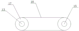
Fig. 1 is a schematic front view of a power distribution control management mechanism with a monitoring function according to the present invention;
fig. 2 is a schematic perspective view of a power distribution control management mechanism with a monitoring function according to the present invention;
FIG. 3 is a schematic top view of a first pulley, a second pulley and a belt of a power distribution control and management mechanism with monitoring function according to the present invention;
FIG. 4 is a schematic structural diagram of part A of a power distribution control and management mechanism with a monitoring function according to the present invention;
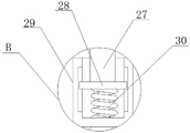
fig. 5 is a schematic structural diagram of part B of a power distribution control and management mechanism with a monitoring function according to the present invention.
In the figure: 1. a box body; 2. an electric motor; 3. a rotating shaft; 4. a device case; 5. a vertical rod; 6. mounting a box; 7. fixing the rod; 8. a first rotating lever; 9. a first bevel gear; 10. a fan; 11. a dust screen; 12. an L-shaped brush bar; 13. a second rotating lever; 14. a cylinder; 15. rotating the rod; 16. a second bevel gear; 17. a first pulley; 18. a belt; 19. connecting blocks; 20. a protective box; 21. a baffle plate; 22. a support plate; 23. a dust collection box; 24. a power distribution control box; 25. a controller; 26. a limiting rod; 27. a support pillar; 28. a slider; 29. a fixed block; 30. a spring; 31. a box door; 32. a vent hole; 33. a second pulley; 34. a third bevel gear.
Detailed Description
The technical solutions in the embodiments will be described clearly and completely with reference to the drawings in the embodiments, and it is obvious that the described embodiments are only a part of the embodiments, but not all embodiments.
Referring to fig. 1-5, distribution control management mechanism with monitoring function, including box 1, one side fixed mounting of box 1 has motor 2, fixed mounting has axis of rotation 3 on the output shaft of motor 2, equal fixed mounting has device case 4 on the both sides inner wall of box 1, equal fixed mounting has montant 5 on the inner wall of two device cases 4, slidable mounting has mounting box 6 on montant 5, the equal fixed mounting in both sides of box 1 has protective housing 20, slidable mounting has backup pad 22 between two device cases 4, the top fixed mounting of backup pad 22 has distribution control box 24, the top fixed mounting of distribution control box 24 has controller 25.
In this embodiment, equal fixed mounting has dead lever 7 on the inner wall of two mounting boxes 6, all rotates on two dead levers 7 and installs first rotation pole 8, and fixed mounting has fan 10 on the first rotation pole 8, and equal fixed mounting has two L shape brush poles 12 in the top and the bottom of two mounting boxes 6, and equal fixed mounting has the brush on two L shape brush poles 12, and a plurality of through-holes have all been seted up to the both sides of box 1.
In this embodiment, equal fixed mounting has second dwang 13 on the bottom inner wall of two device casees 4, and equal fixed mounting has cylinder 14 on two second dwang 13, has seted up the ring channel on the cylinder 14, and movable mounting has connecting block 19 in the ring channel, connecting block 19 and mounting box 6 fixed connection, and the equal fixed mounting in bottom of two device casees 4 has dust collecting box 23, and the inside of controller 25 is equipped with temperature sensor.
In this embodiment, all rotate on two device casees 4 and install rotary rod 15, and equal fixed mounting has first conical gear 9 on two rotary rods 15 and the first rotary rod 8, and two first conical gear 9 mesh mutually, and two rotary rods 15 are telescopic links.
In this embodiment, fixed mounting has two gag lever posts 26 on the top inner wall of box 1, and two gag lever posts 26 all rotate with axis of rotation 3 and are connected, and the rotation hole has been seted up to one side of box 1, and axis of rotation 3 rotates and installs in the rotation hole.
In this embodiment, vertical hole has all been seted up to one side of two device casees 4, and equal fixed mounting has dust screen 11 in two vertical holes, and two brushes all contact with one side of dust screen 11, and chamber door 31 is installed in the outside of box 1.
In this embodiment, a first belt pulley 17 is fixedly installed on the second rotating rod 13, a second belt pulley 33 is fixedly installed on the rotating rod 15, and the same belt 18 is in transmission connection with the first belt pulley 17 and the second belt pulley 33.
In this embodiment, fixed mounting has two fixed blocks 29 on the bottom inner wall of box 1, and the mounting groove has all been seted up at the top of two fixed blocks 29, and equal fixed mounting has spring 30 on the bottom inner wall of two mounting grooves, and the bottom fixed mounting of backup pad 22 has two support columns 27, and the equal fixed mounting in bottom of two support columns 27 has sliding block 28, spring 30's top and sliding block 28 fixed connection.
In this embodiment, two baffles 21 are fixedly mounted on the inner walls of the two protection boxes 20, and the vent holes 32 are formed in one sides of the two protection boxes 20.
In this embodiment, two second bevel gears 16 are fixedly mounted on the rotating shaft 3, third bevel gears 34 are fixedly mounted on both the two rotating rods 15, and the second bevel gears 16 are meshed with the third bevel gears 34.
In this embodiment, when monitoring the distribution control device, the distribution control device is monitored in real time through the temperature sensor, when the temperature of the distribution control device is too high, the temperature sensor transmits a signal to the controller 25 and the worker, when the worker receives the signal, the controller 25 controls the motor 2 to operate, the motor 2 drives the rotating shaft 3 to rotate, and the two rotating rods 15 are driven to rotate through the meshing effect of the two second bevel gears 16 and the third bevel gear 34, because the rotating rod 15 is meshed with the second bevel gear 16 on the first rotating rod 8, when the two rotating rods 15 rotate, the first rotating rod 8 is driven to rotate, and then the two fans 10 are driven to rotate, when the two fans 10 rotate, the distribution control box 24 is blown to dissipate heat, when the two rotating rods 15 rotate, through first belt pulley 17, the effect of second belt pulley 33 and belt 18, will drive two second dwang 13 and take place to rotate, make cylinder 14 take place to rotate, will drive connecting block 19 when cylinder 14 takes place to rotate and take place reciprocating motion from top to bottom, thereby it takes place reciprocating motion to drive mounting box 6 and fan 10, two L shape brush-holder stud 12 of fixed mounting on mounting box 6 will drive brush reciprocating motion from top to bottom this moment, clear up dust screen 11 surface, the dust of clearing up will fall into in dust collecting box 23, the staff only need regularly clear up the dust in the dust collecting box 23 can.
The above description is only a preferred embodiment of the present invention, but the scope of the present invention is not limited thereto, and any person skilled in the art should be considered as the technical solutions and the inventive concepts of the present invention in the technical scope of the present invention.
Claims (10)
1. Distribution control management mechanism with monitoring function, including the box, its characterized in that, one side fixed mounting of box has the motor, fixed mounting has the axis of rotation on the output shaft of motor, equal fixed mounting has the device case, two on the both sides inner wall of box equal fixed mounting has the montant on the inner wall of device case, slidable mounting has the mounting box on the montant, the equal fixed mounting in both sides of box has the protective housing, two slidable mounting has the backup pad between the device case, the top fixed mounting of backup pad has the distribution control box, the top fixed mounting of distribution control box has the controller.
2. The power distribution control and management mechanism with the monitoring function according to claim 1, wherein fixed rods are fixedly mounted on inner walls of the two mounting boxes, a first rotating rod is rotatably mounted on the two fixed rods, a fan is fixedly mounted on the first rotating rod, two L-shaped brush rods are fixedly mounted on top and bottom of the two mounting boxes, brushes are fixedly mounted on the two L-shaped brush rods, and a plurality of through holes are formed in two sides of the box body.
3. The power distribution control and management mechanism with the monitoring function according to claim 1, wherein a second rotating rod is fixedly mounted on each of the two device boxes, a cylinder is fixedly mounted on each of the two second rotating rods, an annular groove is formed in each cylinder, a connecting block is movably mounted in each annular groove, each connecting block is fixedly connected with the corresponding mounting box, a dust collecting box is fixedly mounted at each of the bottoms of the two device boxes, and a temperature sensor is arranged inside each controller.
4. The power distribution control and management mechanism with the monitoring function according to claim 3, wherein two device boxes are rotatably provided with rotating rods, two rotating rods and a first rotating rod are fixedly provided with first bevel gears, the two first bevel gears are meshed, and the two rotating rods are telescopic rods.
5. The power distribution control and management mechanism with the monitoring function according to claim 1, wherein two limiting rods are fixedly installed on an inner wall of a top of the box body, the two limiting rods are rotatably connected with a rotating shaft, a rotating hole is formed in one side of the box body, and the rotating shaft is rotatably installed in the rotating hole.
6. The power distribution control and management mechanism with the monitoring function according to claim 1, wherein vertical holes are formed in one side of each of the two device boxes, a dust screen is fixedly mounted in each of the vertical holes, the two brushes are in contact with one side of the dust screen, and a box door is mounted on the outer side of the box body.
7. The power distribution control and management mechanism with the monitoring function according to claim 4, wherein a first belt pulley is fixedly installed on the second rotating rod, a second belt pulley is fixedly installed on the rotating rod, and the same belt is in transmission connection with the first belt pulley and the second belt pulley.
8. The power distribution control and management mechanism with the monitoring function according to claim 1, wherein two fixed blocks are fixedly installed on the inner wall of the bottom of the box body, mounting grooves are formed in the tops of the two fixed blocks, springs are fixedly installed on the inner walls of the bottoms of the two mounting grooves, two supporting columns are fixedly installed at the bottom of the supporting plate, sliding blocks are fixedly installed at the bottom ends of the two supporting columns, and the top ends of the springs are fixedly connected with the sliding blocks.
9. The power distribution control and management mechanism with the monitoring function according to claim 1, wherein two baffles are fixedly mounted on the inner walls of the two protection boxes, and a vent hole is formed in one side of each of the two protection boxes.
10. The power distribution control and management mechanism with monitoring function according to claim 1, wherein two second bevel gears are fixedly mounted on the rotating shaft, a third bevel gear is fixedly mounted on each of the two rotating rods, and the second bevel gears are meshed with the third bevel gears.
Priority Applications (1)
| Application Number | Priority Date | Filing Date | Title |
|---|---|---|---|
| CN202111604909.4A CN114336369A (en) | 2021-12-25 | 2021-12-25 | Power distribution control management mechanism with monitoring function |
Applications Claiming Priority (1)
| Application Number | Priority Date | Filing Date | Title |
|---|---|---|---|
| CN202111604909.4A CN114336369A (en) | 2021-12-25 | 2021-12-25 | Power distribution control management mechanism with monitoring function |
Publications (1)
| Publication Number | Publication Date |
|---|---|
| CN114336369A true CN114336369A (en) | 2022-04-12 |
Family
ID=81013616
Family Applications (1)
| Application Number | Title | Priority Date | Filing Date |
|---|---|---|---|
| CN202111604909.4A Pending CN114336369A (en) | 2021-12-25 | 2021-12-25 | Power distribution control management mechanism with monitoring function |
Country Status (1)
| Country | Link |
|---|---|
| CN (1) | CN114336369A (en) |
Citations (3)
| Publication number | Priority date | Publication date | Assignee | Title |
|---|---|---|---|---|
| CN205489185U (en) * | 2016-03-07 | 2016-08-17 | 重庆汉嘉电气有限公司 | Alternating current low voltage distribution cabinet |
| CN108847600A (en) * | 2018-07-31 | 2018-11-20 | 河北建筑工程学院 | A kind of rotary jet radiating dustproof electrical cabinet |
| CN213938726U (en) * | 2021-01-18 | 2021-08-10 | 余立新 | Explosion-proof type electrical control box |
-
2021
- 2021-12-25 CN CN202111604909.4A patent/CN114336369A/en active Pending
Patent Citations (3)
| Publication number | Priority date | Publication date | Assignee | Title |
|---|---|---|---|---|
| CN205489185U (en) * | 2016-03-07 | 2016-08-17 | 重庆汉嘉电气有限公司 | Alternating current low voltage distribution cabinet |
| CN108847600A (en) * | 2018-07-31 | 2018-11-20 | 河北建筑工程学院 | A kind of rotary jet radiating dustproof electrical cabinet |
| CN213938726U (en) * | 2021-01-18 | 2021-08-10 | 余立新 | Explosion-proof type electrical control box |
Similar Documents
| Publication | Publication Date | Title |
|---|---|---|
| CN215817019U (en) | Internal environment monitoring device for power distribution cabinet | |
| CN211790191U (en) | Heat dissipation and ventilation device of distribution box | |
| CN114336369A (en) | Power distribution control management mechanism with monitoring function | |
| CN211580386U (en) | Road environment monitoring box | |
| CN210041003U (en) | Electric box of building that heat dispersion is good | |
| CN214798511U (en) | Workshop is with electrical apparatus switch board from taking heat radiation structure | |
| CN111935369A (en) | High-freedom-degree adjusting type mounting device for security monitoring equipment | |
| CN214381720U (en) | Remote 4G data power monitoring terminal | |
| CN215419251U (en) | High-efficient heat abstractor of switch board | |
| CN211481389U (en) | Integrated power background monitoring device for 10KV switching station | |
| CN115560170A (en) | Mobile intelligent security device and use method thereof | |
| CN213304639U (en) | Intelligent outdoor distribution power distribution device | |
| CN212162472U (en) | Equipment electric box | |
| CN210039018U (en) | Fire alarm controller | |
| CN210898016U (en) | Control cabinet for electromechanical engineering | |
| CN209358341U (en) | A kind of motor protection device being equipped with overload protective device | |
| CN109449773B (en) | Electric power cabinet with dust removal and heat dissipation functions | |
| CN112452122A (en) | Good heat dissipation's intelligent mechanical control platform | |
| CN220319408U (en) | Novel burglary-resisting door of water conservancy facility computer lab | |
| CN220754162U (en) | Switch cabinet shell with heat dissipation function | |
| CN219760425U (en) | Electric control cabinet with clamping installation structure | |
| CN217984204U (en) | High-efficient radiating electrical equipment dustproof protection case | |
| CN214706619U (en) | Dust-protection medium-voltage switch cabinet | |
| CN219871319U (en) | Wetland soil supervisory equipment | |
| CN212751443U (en) | Internet of things-based outdoor power control cabinet with built-in heat dissipation protection structure |
Legal Events
| Date | Code | Title | Description |
|---|---|---|---|
| PB01 | Publication | ||
| PB01 | Publication | ||
| SE01 | Entry into force of request for substantive examination | ||
| SE01 | Entry into force of request for substantive examination |