CN114319746B - Multifunctional energy-saving photovoltaic building roof structure - Google Patents
Multifunctional energy-saving photovoltaic building roof structure Download PDFInfo
- Publication number
- CN114319746B CN114319746B CN202210003367.3A CN202210003367A CN114319746B CN 114319746 B CN114319746 B CN 114319746B CN 202210003367 A CN202210003367 A CN 202210003367A CN 114319746 B CN114319746 B CN 114319746B
- Authority
- CN
- China
- Prior art keywords
- photovoltaic
- threaded rod
- fixedly connected
- roof structure
- building roof
- Prior art date
- Legal status (The legal status is an assumption and is not a legal conclusion. Google has not performed a legal analysis and makes no representation as to the accuracy of the status listed.)
- Active
Links
Images


Classifications
-
- Y—GENERAL TAGGING OF NEW TECHNOLOGICAL DEVELOPMENTS; GENERAL TAGGING OF CROSS-SECTIONAL TECHNOLOGIES SPANNING OVER SEVERAL SECTIONS OF THE IPC; TECHNICAL SUBJECTS COVERED BY FORMER USPC CROSS-REFERENCE ART COLLECTIONS [XRACs] AND DIGESTS
- Y02—TECHNOLOGIES OR APPLICATIONS FOR MITIGATION OR ADAPTATION AGAINST CLIMATE CHANGE
- Y02B—CLIMATE CHANGE MITIGATION TECHNOLOGIES RELATED TO BUILDINGS, e.g. HOUSING, HOUSE APPLIANCES OR RELATED END-USER APPLICATIONS
- Y02B10/00—Integration of renewable energy sources in buildings
- Y02B10/10—Photovoltaic [PV]
-
- Y—GENERAL TAGGING OF NEW TECHNOLOGICAL DEVELOPMENTS; GENERAL TAGGING OF CROSS-SECTIONAL TECHNOLOGIES SPANNING OVER SEVERAL SECTIONS OF THE IPC; TECHNICAL SUBJECTS COVERED BY FORMER USPC CROSS-REFERENCE ART COLLECTIONS [XRACs] AND DIGESTS
- Y02—TECHNOLOGIES OR APPLICATIONS FOR MITIGATION OR ADAPTATION AGAINST CLIMATE CHANGE
- Y02B—CLIMATE CHANGE MITIGATION TECHNOLOGIES RELATED TO BUILDINGS, e.g. HOUSING, HOUSE APPLIANCES OR RELATED END-USER APPLICATIONS
- Y02B10/00—Integration of renewable energy sources in buildings
- Y02B10/20—Solar thermal
-
- Y—GENERAL TAGGING OF NEW TECHNOLOGICAL DEVELOPMENTS; GENERAL TAGGING OF CROSS-SECTIONAL TECHNOLOGIES SPANNING OVER SEVERAL SECTIONS OF THE IPC; TECHNICAL SUBJECTS COVERED BY FORMER USPC CROSS-REFERENCE ART COLLECTIONS [XRACs] AND DIGESTS
- Y02—TECHNOLOGIES OR APPLICATIONS FOR MITIGATION OR ADAPTATION AGAINST CLIMATE CHANGE
- Y02E—REDUCTION OF GREENHOUSE GAS [GHG] EMISSIONS, RELATED TO ENERGY GENERATION, TRANSMISSION OR DISTRIBUTION
- Y02E10/00—Energy generation through renewable energy sources
- Y02E10/40—Solar thermal energy, e.g. solar towers
- Y02E10/47—Mountings or tracking
-
- Y—GENERAL TAGGING OF NEW TECHNOLOGICAL DEVELOPMENTS; GENERAL TAGGING OF CROSS-SECTIONAL TECHNOLOGIES SPANNING OVER SEVERAL SECTIONS OF THE IPC; TECHNICAL SUBJECTS COVERED BY FORMER USPC CROSS-REFERENCE ART COLLECTIONS [XRACs] AND DIGESTS
- Y02—TECHNOLOGIES OR APPLICATIONS FOR MITIGATION OR ADAPTATION AGAINST CLIMATE CHANGE
- Y02E—REDUCTION OF GREENHOUSE GAS [GHG] EMISSIONS, RELATED TO ENERGY GENERATION, TRANSMISSION OR DISTRIBUTION
- Y02E10/00—Energy generation through renewable energy sources
- Y02E10/50—Photovoltaic [PV] energy
Abstract
The invention relates to the technical field of buildings and discloses a multifunctional energy-saving photovoltaic building roof structure which comprises a mounting beam and photovoltaic plates, wherein the photovoltaic plates are positioned right above the mounting beam, two sides of the top end of the mounting beam are fixedly connected with L-shaped plates, the photovoltaic plates are positioned at the top ends of the L-shaped plates, and limiting fixing blocks are arranged at the top ends of the mounting beam. This kind of multi-functional energy-saving photovoltaic building roof structure, through being provided with spacing fixed block, place the top of installation roof beam with the photovoltaic board, place the both sides at the photovoltaic board with spacing fixed block, the spring exists elasticity to the card foot, it is prescribe a limit to the position of card foot under the card foot no exogenic action, the bottom of spacing fixed block is laminated with the top of installation roof beam this moment, rotate threaded rod one again, make threaded rod one at spacing fixed block internal downward movement, the inclined plane on card foot top is extruded to the bottom of threaded rod one simultaneously, make two card feet remove to both sides simultaneously, make the bottom and the L shaped plate joint of card foot.
Description
Technical Field
The invention relates to the technical field of buildings, in particular to a multifunctional energy-saving photovoltaic building roof structure.
Background
In current building construction, roof structure is various, in order to satisfy different life demands, the roof can set to light-transmitting type, heat preservation type and easy dismouting etc. and along with people's environmental awareness is constantly reinforcing, energy saving to roof structure requires more and more high, usually people set up solar energy on the roof, solar energy is one kind and obtains more general clean energy, photovoltaic board is the device of solar energy conversion of a general application, carries out the conversion of energy through absorbing heat, because traditional solar energy specification is great and be inconvenient for the installation, consequently need use solar photovoltaic board to replace the installation of traditional solar energy.
When current installation photovoltaic board on the roof, need punch the installation fixed on the photovoltaic board, cause the damage to the body of photovoltaic board, installation operation step is complicated, and work efficiency is low, does not possess waterproof nature simultaneously, and difficulty when adjusting the deflection angle of photovoltaic board.
Disclosure of Invention
Aiming at the defects of the prior art, the invention provides a multifunctional energy-saving photovoltaic building roof structure which has the advantages of convenience in installing a photovoltaic plate, waterproofness and convenience in adjusting the deflection angle of the photovoltaic plate, and solves the problems in the background art.
The invention provides the following technical scheme: a multi-functional energy-efficient photovoltaic building roof structure comprising: the photovoltaic panel is located the installation roof beam directly over, the equal fixedly connected with L shaped plate in both sides on installation roof beam top, the photovoltaic panel is located the top of L shaped plate, spacing fixed block has been placed on the top of installation roof beam, the quantity of spacing fixed block is a plurality of, and a plurality of spacing fixed block is located the both sides of photovoltaic panel respectively, threaded rod one has been pegged graft on the top screw thread of spacing fixed block, the clamp plate has been cup jointed to the surface activity of threaded rod one, the lower surface of clamp plate and the laminating of the upper surface of photovoltaic panel, the equal fixedly connected with mounting panel in bottom of installation roof beam both sides surface, the lower fixed surface of mounting panel is connected with the damping rubber pad, the mounting panel is located the top of crossbeam, the mounting panel passes through bolt and crossbeam fixed connection, the lower surface fixing at crossbeam both ends articulates the piece, two spacing hole two have been seted up to the side of articulation piece.
Preferably, the surface rotation of articulated piece is connected with the swivel post, the bottom of swivel post is through bolt fixedly connected with extension rod, two spacing hole two be the upper and lower range at the one side surface of articulated piece, the central point of crossbeam lower surface puts and rotates and be connected with the pillar.
Preferably, the mounting groove has been seted up to the bottom of spacing fixed block, the equal fixedly connected with telescopic link of both sides inslot wall surface of mounting groove, the other end fixedly connected with card foot of telescopic link, the surface activity of telescopic link has cup jointed the spring, the one end and the one side surface laminating of card foot of spring.
Preferably, the top of installation roof beam is seted up flutedly, the bottom of threaded rod one is located the mounting groove and laminates with the tank bottom surface of recess, the surface laminating of one side surface and threaded rod one of card foot, one side border on card foot top sets up for the inclined plane, the bottom and the L shaped plate joint of card foot.
Preferably, sliding holes are formed in four corners of the top end of the limiting fixing block, inserting rods are fixedly connected to four corners of the lower surface of the pressing plate, and the inserting rods slide and are inserted into the sliding holes.
Preferably, the flat cable buckles are fixedly connected to the surfaces of the two sides of the mounting beam.
Preferably, the top of clamp plate is equipped with the apron, the apron is located two photovoltaic board neighbors, the equal fixedly connected with sealing strip in both sides of apron, the bottom and the upper surface of photovoltaic board of sealing strip closely laminate.
Preferably, the surface activity of apron is pegged graft and is had threaded rod two, the bottom rotation of threaded rod two is connected with the horizontal pole, the sealing washer has been cup jointed on the surface of threaded rod two, the top of sealing washer is equipped with the nut, the nut screw cup joints on the surface of threaded rod two, the lower surface of sealing washer and the laminating of the upper surface of apron.
Preferably, the bottom of the threaded rod II is provided with a semicircular groove, the cross rod is in a fan-shaped columnar arrangement, the cross rod is identical with the semicircular groove in model and specification, and the joint of the semicircular groove and the cross rod is the center position of the cross rod.
Preferably, the lower surface fixedly connected with semicircle ring of crossbeam, semicircle ring is the semicircle form setting, a plurality of spacing hole one has been seted up to one side surface of semicircle ring, a plurality of spacing hole one is the circumference with respect to one side surface of semicircle ring and arranges, peg graft in the spacing hole one and have spacing bolt, the end of spacing bolt runs through spacing hole one and peg graft in one side surface of pillar, the bottom of pillar is through bolt fixedly connected with extension rod.
Compared with the prior art, the invention has the following beneficial effects:
1. this kind of multi-functional energy-saving photovoltaic building roof structure, through being provided with spacing fixed block, place the top of installation roof beam with the photovoltaic board, place the both sides at the photovoltaic board with spacing fixed block, there is elasticity to the card foot in the spring, the position to the card foot is prescribe a limit to under the card foot no exogenic action, the bottom of spacing fixed block and the top laminating of installation roof beam this moment, rotate threaded rod one again, make threaded rod one at spacing fixed block internal downward movement, the inclined plane on card foot top is extruded to the bottom of threaded rod one simultaneously, make two card feet remove to both sides simultaneously, make the bottom and the L shaped plate joint of card foot, can compress tightly spacing fixed block fixed mounting on the installation roof beam with threaded rod one pair of clamp plate simultaneously, make the border of clamp plate compress tightly the photovoltaic board, fix the position of photovoltaic board above the installation roof beam, avoid punching on the photovoltaic board and install fixedly, make the photovoltaic board operate simple and swiftly and can not cause the damage at the installation fixedly when the installation.
2. This kind of multi-functional energy-saving photovoltaic building roof structure, through being provided with the apron, when a plurality of photovoltaic boards splice the installation, there is the clearance between photovoltaic board and the photovoltaic board, place the apron on the clearance between photovoltaic board and photovoltaic board, the bottom of sealing strip and the upper surface laminating of photovoltaic board this moment, avoided rubbish or rainwater to flow in from the clearance of two adjacent photovoltaic boards, great improvement the rain-proof function of device, when passing threaded rod two from the round hole on apron surface, rotatable horizontal pole, make the horizontal pole be located the semicircle inslot and constitute complete cylindric, conveniently pass in the round hole on apron surface, when horizontal pole is perpendicular to threaded rod two sets up, the surface of horizontal pole and the laminating of photovoltaic board, the rotation nut simultaneously, make the horizontal pole have ascending effort, the horizontal pole is connected with light Fu Banka this moment, fix the position of two, be convenient for to cover plate fixed mounting in adjacent place.
3. This kind of multi-functional energy-saving photovoltaic building roof structure rotates on the top of pillar through the crossbeam, can pass spacing bolt simultaneously and peg graft in the pillar in spacing hole one, can adjust fixedly the contained angle of crossbeam on the pillar top, conveniently adjusts the angle of photovoltaic board, improves the suitability of device greatly, simultaneously two setting of spacing hole two splice two adjacent crossbeams, carries out fixed connection adjacent two articulated pieces, can make things convenient for a plurality of crossbeams to splice.
Drawings
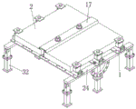
FIG. 1 is a schematic diagram of the overall structure of the device of the present invention;
FIG. 2 is a schematic view of the beam structure of the present invention;
FIG. 3 is a schematic diagram of a cover plate structure according to the present invention;
FIG. 4 is a schematic view of the mounting beam structure of the present invention;
fig. 5 is a schematic diagram of a cross-sectional structure of a limiting fixing block according to the present invention.
In the figure: 1. mounting a beam; 2. a photovoltaic panel; 3. limiting fixed blocks; 4. a mounting groove; 5. a telescopic rod; 6. a clamping foot; 7. a spring; 8. an L-shaped plate; 9. a groove; 10. a mounting plate; 11. vibration damping rubber pads; 12. a winding displacement buckle; 13. a slide hole; 14. a first threaded rod; 15. a pressing plate; 16. a rod; 17. a cover plate; 18. a second threaded rod; 19. a semicircular groove; 20. a nut; 21. a seal ring; 22. a sealing strip; 23. a cross bar; 24. a cross beam; 25. a support post; 26. a semicircular ring; 27. a first limiting hole; 28. a limit bolt; 29. a hinge block; 30. a limiting hole II; 31. a rotating column; 32. an extension rod.
Detailed Description
The following description of the embodiments of the present invention will be made clearly and completely with reference to the accompanying drawings, in which it is apparent that the embodiments described are only some embodiments of the present invention, but not all embodiments. All other embodiments, which can be made by those skilled in the art based on the embodiments of the invention without making any inventive effort, are intended to be within the scope of the invention.
Example 1
Referring to fig. 1-5, a multifunctional energy-saving photovoltaic building roof structure comprises a mounting beam 1 and a photovoltaic panel 2, wherein the photovoltaic panel 2 is positioned right above the mounting beam 1, two sides of the top end of the mounting beam 1 are fixedly connected with an L-shaped plate 8, the photovoltaic panel 2 is positioned at the top end of the L-shaped plate 8, a limit fixing block 3 is arranged at the top end of the mounting beam 1, the number of the limit fixing blocks 3 is a plurality of, the limit fixing blocks 3 are respectively positioned at two sides of the photovoltaic panel 2, the top end of the limit fixing block 3 is in threaded connection with a threaded rod 14, the surface of the threaded rod 14 is movably sleeved with a pressing plate 15, the lower surface of the pressing plate 15 is attached to the upper surface of the photovoltaic panel 2, the bottom ends of the two side surfaces of the mounting beam 1 are fixedly connected with mounting plates 10, the lower surface of the mounting plates 10 are fixedly connected with damping rubber pads 11, the mounting plates 10 are positioned above a cross beam 24, the mounting plate 10 is fixedly connected with the cross beam 24 through bolts, the lower surfaces of the two ends of the cross beam 24 are fixedly provided with hinging blocks 29, the side surfaces of the hinging blocks 29 are provided with two limiting holes II 30, the bottom end of each limiting fixed block 3 is provided with a mounting groove 4, the inner wall surfaces of the two side grooves of each mounting groove 4 are fixedly connected with a telescopic rod 5, the other end of each telescopic rod 5 is fixedly connected with a clamping foot 6, the surface of each telescopic rod 5 is movably sleeved with a spring 7, one end of each spring 7 is jointed with one side surface of each clamping foot 6, the springs 7 have elasticity on the corresponding clamping foot 6, the positions of the corresponding clamping feet 6 are limited under the action of no external force of the corresponding clamping foot 6, at the moment, the bottom ends of the limiting fixed blocks 3 are jointed with the top ends of the mounting beams 1, the top ends of the mounting beams 1 are provided with grooves 9, the bottom ends of the first 14 are positioned in the mounting grooves 4 and are jointed with the bottom surfaces of the grooves 9, one side surfaces of the corresponding threaded rods 6 are jointed with the surfaces of the threaded rods 14, one side edge of the top end of the clamping foot 6 is an inclined surface, the bottom end of the clamping foot 6 is clamped with the L-shaped plate 8, the first threaded rod 14 is rotated, the first threaded rod 14 moves downwards in the limiting fixed block 3, meanwhile, the bottom end of the first threaded rod 14 extrudes the inclined surface of the top end of the clamping foot 6, so that the two clamping feet 6 move towards two sides at the same time, the bottom end of the clamping foot 6 is clamped with the L-shaped plate 8, the limiting fixed block 3 can be fixedly arranged on the mounting beam 1, meanwhile, the first threaded rod 14 compresses the pressing plate 15, the pressing plate 15 compresses the edge of the photovoltaic plate 2, the photovoltaic plate 2 is fixed at the position above the mounting beam 1, sliding holes 13 are respectively formed in four corners of the top end of the limiting fixed block 3, inserting rods 16 are fixedly connected with the four corners of the lower surface of the pressing plate 15, the inserting rods 16 slide and are spliced with the sliding holes 13, the positions of the pressing plate 15 are limited, the two side surfaces of the mounting beam 1 are fixedly connected with flat cable buckles 12, the flat cable is convenient, the cover plate 17 is arranged above the pressing plate 15, the cover plate 17 is positioned at the adjacent position of the two photovoltaic plates 2, the two sides of the cover plate 17 are fixedly connected with the sealing strips 22, the bottom ends of the sealing strips 22 are tightly attached to the upper surfaces of the photovoltaic plates 2, garbage or rainwater is prevented from flowing in from the gap between the two adjacent photovoltaic plates 2, the rainproof function of the device is greatly improved, the surface of the cover plate 17 is movably inserted with the threaded rod II 18, the bottom end of the threaded rod II 18 is rotationally connected with the cross rod 23, the surface of the threaded rod II 18 is sheathed with the sealing ring 21, the nut 20 is arranged above the sealing ring 21, the threads of the nut 20 are sheathed on the surface of the threaded rod II 18, the lower surface of the sealing ring 21 is attached to the upper surface of the cover plate 17, the tightness is improved, the semicircular groove 19 is arranged at the bottom end of the threaded rod II 18, the cross rod 23 is in a fan-shaped columnar arrangement, the cross rod 23 is in accordance with the specification of the semicircular groove 19, the junction of semicircle groove 19 and horizontal pole 23 is the central point of horizontal pole 23, when passing threaded rod two 18 from the round hole on apron 17 surface, rotatable horizontal pole 23 makes horizontal pole 23 be arranged in semicircle groove 19 and constitutes complete cylindric, conveniently pass in the round hole on apron 17 surface, when horizontal pole 23 sets up perpendicularly about threaded rod two 18 simultaneously, the surface laminating of horizontal pole 23 and the lower surface of photovoltaic board 2, simultaneously rotate nut 20 for horizontal pole 23 has ascending effort, at this moment horizontal pole 23 and photovoltaic board 2 joint, the fixed to the position of threaded rod two 18, be convenient for to apron 17 fixed mounting in the adjacent place.
Example two
According to an embodiment one, as in fig. 1-5, comprising: the installation beam 1 and the photovoltaic panel 2, the photovoltaic panel 2 is located right above the installation beam 1, both sides of the top end of the installation beam 1 are fixedly connected with the L-shaped plate 8, the photovoltaic panel 2 is located at the top end of the L-shaped plate 8, the top end of the installation beam 1 is provided with a plurality of limit fixed blocks 3, the limit fixed blocks 3 are respectively located at both sides of the photovoltaic panel 2, the top end thread of the limit fixed block 3 is inserted with a first threaded rod 14, the surface of the first threaded rod 14 is movably sleeved with a pressing plate 15, the lower surface of the pressing plate 15 is attached to the upper surface of the photovoltaic panel 2, the bottom ends of both side surfaces of the installation beam 1 are fixedly connected with installation plates 10, the lower surface of the installation plates 10 are fixedly connected with damping rubber pads 11, the installation plates 10 are located above the cross beams 24, the installation plates 10 are fixedly connected with the cross beams 24 through bolts, the lower surfaces of both ends of the cross beams 24 are fixedly provided with hinging blocks 29, two limiting holes II 30 are formed in the side face of the hinging block 29, a rotating column 31 is rotatably connected to the surface of the hinging block 29, an extension rod 32 is fixedly connected to the bottom end of the rotating column 31 through bolts, the two limiting holes II 30 are vertically arranged on one side surface of the hinging block 29, a strut 25 is rotatably connected to the center position of the lower surface of the cross beam 24, a semicircular ring 26 is fixedly connected to the lower surface of the cross beam 24, the semicircular ring 26 is arranged in a semicircular shape, a plurality of limiting holes I27 are formed in one side surface of the semicircular ring 26, a plurality of limiting holes I27 are circumferentially arranged on one side surface of the semicircular ring 26, limiting bolts 28 are inserted into the limiting holes I27, the ends of the limiting bolts 28 are inserted into one side surface of the strut 25 through the limiting holes I27, the limiting bolts 28 are inserted into the strut 25 through the limiting holes I27, the included angle of the top end of the cross beam 24 can be adjusted and fixed, the angle of the photovoltaic panel 2 is conveniently adjusted, the suitability of the device is greatly improved, the bottom end of the support column 25 is fixedly connected with the extension rod 32 through the bolt, the height of the support column 25 is convenient to adjust, meanwhile, the two limiting holes II 30 are arranged to splice two adjacent cross beams 24, the two adjacent hinge blocks 29 are fixedly connected, and a plurality of cross beams 24 can be conveniently spliced.
Working principle: when the device is used, the photovoltaic panel 2 is placed above the mounting beam 1, the limiting fixed blocks 3 are placed on two sides of the photovoltaic panel 2, the springs 7 are used for limiting the positions of the clamping pins 6 under the action of no external force of the clamping pins 6, at the moment, the bottom ends of the limiting fixed blocks 3 are attached to the top ends of the mounting beam 1, the first threaded rod 14 is rotated, the first threaded rod 14 moves downwards in the limiting fixed blocks 3, meanwhile, the bottom ends of the first threaded rod 14 extrude the inclined surfaces at the top ends of the clamping pins 6, so that the two clamping pins 6 move towards two sides at the same time, the bottom ends of the clamping pins 6 are clamped with the L-shaped plates 8, the limiting fixed blocks 3 can be fixedly mounted on the mounting beam 1, the first threaded rod 14 compresses the pressing plates 15, the pressing plates 15 compress the edges of the photovoltaic panel 2, the photovoltaic panel 2 is fixed at the positions above the mounting beam 1, when a plurality of photovoltaic panels 2 are spliced and installed, gaps exist between the photovoltaic panels 2 and 2, the cover plate 17 is placed on the gaps between the photovoltaic panels 2 and 2, at the moment, the bottom ends of the sealing strips 22 are attached to the upper surfaces of the photovoltaic panels 2, garbage or rainwater is prevented from flowing into the gaps between the two adjacent photovoltaic panels 2, the rainproof function of the device is greatly improved, when the threaded rod II 18 passes through round holes in the surfaces of the cover plates 17, the cross rod 23 can be rotated, the cross rod 23 is positioned in the semicircular groove 19 to form a complete cylinder shape, so that the threaded rod II passes through the round holes in the surfaces of the cover plate 17 conveniently, and meanwhile, when the cross rod 23 is vertically arranged relative to the threaded rod II 18, the surfaces of the cross rod 23 are attached to the lower surfaces of the photovoltaic panels 2, and meanwhile, the nuts 20 are rotated, so that upward acting forces exist on the cross rod 23 is clamped with the photovoltaic panels 2, the position of the threaded rod II 18 is fixed, the cover plate 17 is fixedly installed, the limiting bolt 28 penetrates through the first limiting hole 27 and is inserted into the strut 25, the included angle of the cross beam 24 at the top end of the strut 25 can be adjusted and fixed, the angle of the photovoltaic panel 2 can be adjusted conveniently, and the applicability of the device is greatly improved.
It is noted that relational terms such as first and second, and the like are used solely to distinguish one entity or action from another entity or action without necessarily requiring or implying any actual such relationship or order between such entities or actions. Moreover, the terms "comprises," "comprising," or any other variation thereof, are intended to cover a non-exclusive inclusion, such that a process, method, article, or apparatus that comprises a list of elements does not include only those elements but may include other elements not expressly listed or inherent to such process, method, article, or apparatus.
Although embodiments of the present invention have been shown and described, it will be understood by those skilled in the art that various changes, modifications, substitutions and alterations can be made therein without departing from the principles and spirit of the invention, the scope of which is defined in the appended claims and their equivalents.
Claims (8)
1. A multi-functional energy-efficient photovoltaic building roof structure, comprising: the photovoltaic device comprises an installation beam (1) and a photovoltaic plate (2), wherein the photovoltaic plate (2) is positioned right above the installation beam (1), two sides of the top end of the installation beam (1) are fixedly connected with L-shaped plates (8), the photovoltaic plate (2) is positioned at the top end of the L-shaped plates (8), the top end of the installation beam (1) is provided with limiting fixed blocks (3), the number of the limiting fixed blocks (3) is a plurality of, the limiting fixed blocks (3) are respectively positioned at two sides of the photovoltaic plate (2), the top end of each limiting fixed block (3) is in threaded connection with a first threaded rod (14), the surface of each first threaded rod (14) is movably sleeved with a pressing plate (15), the lower surfaces of the pressing plates (15) are attached to the upper surfaces of the photovoltaic plate (2), the bottom ends of the two side surfaces of the installation beam (1) are fixedly connected with mounting plates (10), the lower surfaces of the mounting plates (10) are fixedly connected with rubber pads (11), the mounting plates (10) are positioned above a cross beam (24), the two end surfaces of the mounting plates (10) are fixedly connected with two cross beams (29), and two side surfaces of the cross beams (29) are fixedly hinged with two side surfaces of the cross beams (29);
the bottom end of the limiting fixed block (3) is provided with a mounting groove (4), the inner wall surfaces of grooves on two sides of the mounting groove (4) are fixedly connected with telescopic rods (5), the other ends of the telescopic rods (5) are fixedly connected with clamping feet (6), the surfaces of the telescopic rods (5) are movably sleeved with springs (7), and one ends of the springs (7) are attached to one side surface of the clamping feet (6);
the top of installation roof beam (1) is seted up flutedly (9), the bottom of threaded rod one (14) is located mounting groove (4) and laminates with the tank bottom surface of recess (9), the surface laminating of one side surface and threaded rod one (14) of card foot (6), the one side border on card foot (6) top sets up for the inclined plane, the bottom and the L shaped plate (8) joint of card foot (6).
2. A multi-functional energy efficient photovoltaic building roof structure according to claim 1, characterized in that: the surface rotation of articulated piece (29) is connected with swivel post (31), the bottom of swivel post (31) is through bolt fixedly connected with extension rod (32), two spacing hole two (30) are arranged from top to bottom in the one side surface of articulated piece (29), the central point of crossbeam (24) lower surface puts and rotates and be connected with pillar (25).
3. A multi-functional energy efficient photovoltaic building roof structure according to claim 1, characterized in that: slide holes (13) are formed in four corners of the top end of the limiting fixed block (3), inserting rods (16) are fixedly connected to four corners of the lower surface of the pressing plate (15), and the inserting rods (16) slide and are inserted into the slide holes (13).
4. A multi-functional energy efficient photovoltaic building roof structure according to claim 1, characterized in that: the two side surfaces of the mounting beam (1) are fixedly connected with flat cable buckles (12).
5. A multi-functional energy efficient photovoltaic building roof structure according to claim 1, characterized in that: the top of clamp plate (15) is equipped with apron (17), apron (17) are located two photovoltaic board (2) adjacent departments, the both sides of apron (17) are all fixedly connected with sealing strip (22), the bottom of sealing strip (22) is closely laminated with the upper surface of photovoltaic board (2).
6. The multi-functional energy-efficient photovoltaic building roof structure of claim 5, wherein: the surface activity of apron (17) is pegged graft and is had threaded rod two (18), the bottom rotation of threaded rod two (18) is connected with horizontal pole (23), sealing washer (21) have been cup jointed on the surface of threaded rod two (18), the top of sealing washer (21) is equipped with nut (20), nut (20) screw thread cup joints the surface at threaded rod two (18), the lower surface of sealing washer (21) is laminated with the upper surface of apron (17).
7. The multi-functional energy-efficient photovoltaic building roof structure of claim 6, wherein: the bottom of threaded rod two (18) has seted up semicircle groove (19), horizontal pole (23) are fan-shaped column setting, horizontal pole (23) are identical with the model specification of semicircle groove (19), the junction of semicircle groove (19) and horizontal pole (23) is the central point of horizontal pole (23).
8. A multi-functional energy efficient photovoltaic building roof structure according to claim 2, characterized in that: the lower surface fixedly connected with semicircle ring (26) of crossbeam (24), semicircle ring (26) are semicircle form setting, a plurality of spacing hole (27) have been seted up on one side surface of semicircle ring (26), a plurality of spacing hole (27) are the circumference with respect to one side surface of semicircle ring (26) and are arranged, peg graft in spacing hole (27) have spacing bolt (28), the end of spacing bolt (28) runs through spacing hole (27) and pegs graft on one side surface of pillar (25), the bottom of pillar (25) is through bolt fixedly connected with extension rod (32).
Priority Applications (1)
| Application Number | Priority Date | Filing Date | Title |
|---|---|---|---|
| CN202210003367.3A CN114319746B (en) | 2022-01-05 | 2022-01-05 | Multifunctional energy-saving photovoltaic building roof structure |
Applications Claiming Priority (1)
| Application Number | Priority Date | Filing Date | Title |
|---|---|---|---|
| CN202210003367.3A CN114319746B (en) | 2022-01-05 | 2022-01-05 | Multifunctional energy-saving photovoltaic building roof structure |
Publications (2)
| Publication Number | Publication Date |
|---|---|
| CN114319746A CN114319746A (en) | 2022-04-12 |
| CN114319746B true CN114319746B (en) | 2023-04-28 |
Family
ID=81022927
Family Applications (1)
| Application Number | Title | Priority Date | Filing Date |
|---|---|---|---|
| CN202210003367.3A Active CN114319746B (en) | 2022-01-05 | 2022-01-05 | Multifunctional energy-saving photovoltaic building roof structure |
Country Status (1)
| Country | Link |
|---|---|
| CN (1) | CN114319746B (en) |
Families Citing this family (1)
| Publication number | Priority date | Publication date | Assignee | Title |
|---|---|---|---|---|
| CN117513658B (en) * | 2024-01-04 | 2024-04-16 | 安徽华之语建筑工程有限公司 | Fixing assembly for photovoltaic integrated roof construction |
Citations (10)
| Publication number | Priority date | Publication date | Assignee | Title |
|---|---|---|---|---|
| WO2012082806A2 (en) * | 2010-12-13 | 2012-06-21 | Zep Solar, Inc. | Discrete attachment point apparatus and system for photovoltaic arrays |
| JP3191254U (en) * | 2014-04-04 | 2014-06-12 | 士勤 周 | Solar panel mounting fixing structure |
| JP2016017315A (en) * | 2014-07-08 | 2016-02-01 | 株式会社サンレール | Car port with solar power generation function |
| JP2017040065A (en) * | 2015-08-18 | 2017-02-23 | ブラスト株式会社 | Photovoltaic power generation panel attachment metal fitting |
| WO2017181305A1 (en) * | 2016-04-22 | 2017-10-26 | 宁波大智机械科技有限公司 | Roof-tile connection structure for solar photovoltaic panel |
| CN207766211U (en) * | 2018-01-06 | 2018-08-24 | 海宁川达科技有限公司 | A kind of photovoltaic board connecting equipment |
| JP2019011567A (en) * | 2017-06-29 | 2019-01-24 | 連豐 薛 | Improvement structure of solar cell roof |
| CN209748462U (en) * | 2019-04-24 | 2019-12-06 | 无锡光电宝新能源科技有限公司 | Various steel tile roof photovoltaic power plant mounting structure |
| CN217079443U (en) * | 2022-04-02 | 2022-07-29 | 江苏林江光伏设备有限公司 | Waterproof building integrated photovoltaic device |
| CN115680214A (en) * | 2022-10-28 | 2023-02-03 | 江苏华木空间结构有限公司 | Photovoltaic roof system |
Family Cites Families (8)
| Publication number | Priority date | Publication date | Assignee | Title |
|---|---|---|---|---|
| FR2915217B1 (en) * | 2007-04-20 | 2009-07-10 | Imphy Alloys Sa | STRUCTURE FOR THE MOUNTING IN A WALL OF A BATIS BUILDING FOR SUPPORTING PANELS SUCH AS PHOTOVOLTAIC PANELS |
| US10054336B2 (en) * | 2010-03-03 | 2018-08-21 | Robert M. M. Haddock | Photovoltaic module mounting assembly |
| US20150218822A1 (en) * | 2012-09-03 | 2015-08-06 | Wade Blazley | Composite solar roof |
| US9825581B2 (en) * | 2013-11-14 | 2017-11-21 | Ecolibrium Solar, Inc. | Modular sloped roof solar mounting system |
| US9985575B2 (en) * | 2014-04-07 | 2018-05-29 | Rillito River Solar, Llc | Height adjustment bracket for roof applications |
| US9806668B2 (en) * | 2014-09-23 | 2017-10-31 | Solarcity Corporation | Photovoltaic mounting system for tiled roofs |
| US10469023B2 (en) * | 2016-09-12 | 2019-11-05 | EcoFasten Solar, LLC | Roof mounting system |
| JP6775126B2 (en) * | 2016-09-30 | 2020-10-28 | パナソニックIpマネジメント株式会社 | Solar power generator |
-
2022
- 2022-01-05 CN CN202210003367.3A patent/CN114319746B/en active Active
Patent Citations (10)
| Publication number | Priority date | Publication date | Assignee | Title |
|---|---|---|---|---|
| WO2012082806A2 (en) * | 2010-12-13 | 2012-06-21 | Zep Solar, Inc. | Discrete attachment point apparatus and system for photovoltaic arrays |
| JP3191254U (en) * | 2014-04-04 | 2014-06-12 | 士勤 周 | Solar panel mounting fixing structure |
| JP2016017315A (en) * | 2014-07-08 | 2016-02-01 | 株式会社サンレール | Car port with solar power generation function |
| JP2017040065A (en) * | 2015-08-18 | 2017-02-23 | ブラスト株式会社 | Photovoltaic power generation panel attachment metal fitting |
| WO2017181305A1 (en) * | 2016-04-22 | 2017-10-26 | 宁波大智机械科技有限公司 | Roof-tile connection structure for solar photovoltaic panel |
| JP2019011567A (en) * | 2017-06-29 | 2019-01-24 | 連豐 薛 | Improvement structure of solar cell roof |
| CN207766211U (en) * | 2018-01-06 | 2018-08-24 | 海宁川达科技有限公司 | A kind of photovoltaic board connecting equipment |
| CN209748462U (en) * | 2019-04-24 | 2019-12-06 | 无锡光电宝新能源科技有限公司 | Various steel tile roof photovoltaic power plant mounting structure |
| CN217079443U (en) * | 2022-04-02 | 2022-07-29 | 江苏林江光伏设备有限公司 | Waterproof building integrated photovoltaic device |
| CN115680214A (en) * | 2022-10-28 | 2023-02-03 | 江苏华木空间结构有限公司 | Photovoltaic roof system |
Also Published As
| Publication number | Publication date |
|---|---|
| CN114319746A (en) | 2022-04-12 |
Similar Documents
| Publication | Publication Date | Title |
|---|---|---|
| CN114319746B (en) | Multifunctional energy-saving photovoltaic building roof structure | |
| CN102184982A (en) | Installation assembly and installation method for solar cell panel | |
| CN110130490B (en) | Photovoltaic pergola structure | |
| CN105827192A (en) | Easy-to-adjust photovoltaic bracket and mounting method thereof | |
| CN210518183U (en) | Connecting support of solar cell panel | |
| CN209817099U (en) | Large-span steel house room bearing structure | |
| CN111010070A (en) | Efficient support frame for solar energy | |
| CN215726012U (en) | Building engineering building site environment detects uses removal detection device | |
| CN213402903U (en) | Photovoltaic power generation device for color steel tile roof | |
| CN111648516B (en) | Large-span external-floating-eave assembled ceiling structure and construction method | |
| CN213897827U (en) | Simple trapezoidal color steel tile roof clamp | |
| CN210536562U (en) | Lightweight glass tile roof aluminum alloy photovoltaic support | |
| CN210444219U (en) | Section bar frame of borduring based on photovoltaic aluminum product installation location | |
| CN114108896A (en) | Curtain wall structure with heat insulation material | |
| CN207588764U (en) | Double V-shaped stent and solar energy roof system | |
| CN220368631U (en) | Photovoltaic panel support | |
| CN213927155U (en) | Photovoltaic power generation panel support for color steel tile roof | |
| CN215716659U (en) | Various steel tile roof photovoltaic support with angle adjustment mechanism | |
| CN210867563U (en) | Framework of various steel tile roofing photovoltaic support | |
| CN219569371U (en) | Waterproof type roof pedal and solar photovoltaic support | |
| CN220273600U (en) | Wind-resistant photovoltaic module mounting bracket | |
| CN217711399U (en) | Photovoltaic roof board for building | |
| CN215211527U (en) | Steel constructs component convenient to connect | |
| CN117394762B (en) | Waterproof construction is connected to photovoltaic roofing | |
| CN214090310U (en) | Effectual building structure of anti-wind rain |
Legal Events
| Date | Code | Title | Description |
|---|---|---|---|
| PB01 | Publication | ||
| PB01 | Publication | ||
| SE01 | Entry into force of request for substantive examination | ||
| SE01 | Entry into force of request for substantive examination | ||
| GR01 | Patent grant | ||
| GR01 | Patent grant |