CN114242535A - Manual opening and closing device of 12KV circuit breaker - Google Patents
Manual opening and closing device of 12KV circuit breaker Download PDFInfo
- Publication number
- CN114242535A CN114242535A CN202111578950.9A CN202111578950A CN114242535A CN 114242535 A CN114242535 A CN 114242535A CN 202111578950 A CN202111578950 A CN 202111578950A CN 114242535 A CN114242535 A CN 114242535A
- Authority
- CN
- China
- Prior art keywords
- closing
- connecting lever
- switching
- opening
- circuit breaker
- Prior art date
- Legal status (The legal status is an assumption and is not a legal conclusion. Google has not performed a legal analysis and makes no representation as to the accuracy of the status listed.)
- Pending
Links
- 230000007246 mechanism Effects 0.000 claims abstract description 50
- 230000005540 biological transmission Effects 0.000 claims abstract description 22
- 230000001681 protective effect Effects 0.000 claims description 9
- 238000010586 diagram Methods 0.000 description 3
- 230000033001 locomotion Effects 0.000 description 3
- 238000012423 maintenance Methods 0.000 description 3
- 238000000034 method Methods 0.000 description 3
- XEEYBQQBJWHFJM-UHFFFAOYSA-N Iron Chemical group [Fe] XEEYBQQBJWHFJM-UHFFFAOYSA-N 0.000 description 1
- 230000007547 defect Effects 0.000 description 1
- 238000005259 measurement Methods 0.000 description 1
Images


Classifications
-
- H—ELECTRICITY
- H01—ELECTRIC ELEMENTS
- H01H—ELECTRIC SWITCHES; RELAYS; SELECTORS; EMERGENCY PROTECTIVE DEVICES
- H01H71/00—Details of the protective switches or relays covered by groups H01H73/00 - H01H83/00
- H01H71/10—Operating or release mechanisms
- H01H71/50—Manual reset mechanisms which may be also used for manual release
-
- H—ELECTRICITY
- H01—ELECTRIC ELEMENTS
- H01H—ELECTRIC SWITCHES; RELAYS; SELECTORS; EMERGENCY PROTECTIVE DEVICES
- H01H33/00—High-tension or heavy-current switches with arc-extinguishing or arc-preventing means
- H01H33/60—Switches wherein the means for extinguishing or preventing the arc do not include separate means for obtaining or increasing flow of arc-extinguishing fluid
- H01H33/66—Vacuum switches
- H01H33/666—Operating arrangements
Abstract
A manual switching-on and switching-off device of a 12KV circuit breaker relates to the technical field of high-voltage switches and comprises a box body, a permanent magnet mechanism, a transmission supporting rod, a switching-on limiting groove, a switching-off limiting groove, a connecting lever, a switching-on operating handle and a switching-off operating handle, wherein the connecting lever is connected with a switching-on tooth and a switching-off tooth; a mechanism supporting plate is connected above the permanent magnetic mechanism, a closing connecting lever supporting seat is connected to the mechanism supporting plate, the middle part of the closing connecting lever is hinged to the closing connecting lever supporting seat, one end of the closing connecting lever is arranged right below a closing tooth, the other end of the closing connecting lever is hinged to a closing overturning block, a roller is connected to the closing overturning block, a circle of supporting rod boss is integrally arranged on the transmission supporting rod, and the roller is arranged below the supporting rod boss; the mechanism supporting plate is also connected with a brake separating connecting lever supporting seat, a brake separating connecting lever is hinged in the brake separating connecting lever supporting seat, one end of the brake separating connecting lever is arranged right above the brake separating teeth, and the other end of the brake separating connecting lever is arranged above the supporting rod boss. The invention realizes the manual opening and closing operation.
Description
Technical Field
The invention relates to the technical field of high-voltage switches.
Background
The 12KV outdoor intelligent vacuum circuit breaker has the functions of measurement, control, protection and the like, and the safe and stable operation of a power system is guaranteed. The traditional permanent magnet vacuum circuit breaker mainly comprises a box body and three groups of circuit breaker single-stage mechanisms, wherein each circuit breaker single-stage mechanism comprises a permanent magnet mechanism, a transmission supporting rod and a vacuum arc extinguish chamber, the lower end of the transmission supporting rod is connected with an inner iron core of the permanent magnet mechanism, the upper end of the transmission supporting rod is arranged in the vacuum arc extinguish chamber, and the arc extinguish chamber contact is closed and switched on by lifting the transmission supporting rod; when the transmission supporting rod descends to be separated from the contact of the arc extinguish chamber, the opening is realized. However, the switching-on operation of the permanent magnet operating mechanism with the structure can only be controlled by the coil, and once the situation that the secondary operating control circuit fails to supply power to the switching-on coil occurs, the mechanism cannot complete the switching-on operation, so that inconvenience is brought to the maintenance of field operation and maintenance personnel. The 12KV permanent magnet circuit breaker product in the current market still has the problem of short structure which cannot be manually switched on.
Disclosure of Invention
The invention aims to overcome the defects of the prior art and provides a manual opening and closing device of a 12KV circuit breaker, which realizes manual opening and closing operation.
The purpose of the invention is realized as follows: a manual switching-on and switching-off device of a 12KV circuit breaker comprises a box body and three groups of circuit breaker single-stage mechanisms, wherein each circuit breaker single-stage mechanism comprises a permanent magnet mechanism and a transmission supporting rod, one side of the box body is connected with a protective cover, and a switching-on limiting groove and a switching-off limiting groove are formed in the protective cover; the box body is provided with an operating connecting lever mechanism, the operating connecting lever mechanism comprises a connecting lever, a closing operation handle and an opening operation handle, the connecting lever is supported on the box body, the closing tooth and the opening tooth are connected to the connecting lever, the closing operation handle and the opening operation handle are both connected to one end of the connecting lever, the closing operation handle and the closing limiting groove are arranged correspondingly, and the opening operation handle and the opening limiting groove are arranged correspondingly; a mechanism supporting plate is connected above the permanent magnetic mechanism, a closing connecting arm supporting seat is connected to the mechanism supporting plate, a closing connecting arm is arranged in the closing connecting arm supporting seat, the middle of the closing connecting arm is hinged to the closing connecting arm supporting seat, the closing connecting arm is connected with the closing connecting arm supporting seat through a spring, one end of the closing connecting arm is arranged right below a closing tooth, the other end of the closing connecting arm is hinged to a closing overturning block, a roller is connected in the closing overturning block, a circle of supporting rod boss is integrally arranged on the transmission supporting rod, and the roller is arranged below the supporting rod boss; still connect the separating brake connecting lever supporting seat in the mechanism backup pad, articulated separating brake connecting lever in the separating brake connecting lever supporting seat, the one end setting of separating brake connecting lever is directly over the separating brake tooth, and the other end setting of separating brake connecting lever is in the top of bracing piece boss.
The invention has a set of manual opening structure, a set of manual closing structure and a set of operation structure. The manual opening and closing structure is based on the mechanism supporting plate, and the original space of the transmission supporting position of the permanent magnet mechanism is reasonably utilized. When the circuit breaker needs to be switched on, the switching-on operation of the circuit breaker can be completed only by pulling or pressing the operation connecting lever to drive the manual switching-on structure to act; when the breaker needs to be opened, the breaker can be opened only by pulling or pressing the operating crank arm to drive the manual opening structure to move.
The invention can effectively solve the problem of short plates inherent in the prior art of permanent magnet vacuum circuit breaker products, is convenient for field operation and maintenance personnel to overhaul and operate, improves the working efficiency, reduces the time range of power failure influence, and provides a design thought for manual opening and closing operation of other voltage-class permanent magnet vacuum circuit breaker products.
In order to make the closing more stable and reliable, each mechanism supporting plate is provided with two closing connecting lever supporting seats, two closing connecting levers, two closing turning blocks, two rollers and two springs, and the opening connecting lever supporting seat is arranged between the two closing connecting lever supporting seats; the circuit breaker single-stage mechanism corresponds to one opening tooth and two closing teeth, the opening tooth is arranged between the two closing teeth, and one end of each of the two closing connecting levers corresponds to the two closing teeth.
One end of the opening crank arm, which faces the support boss, is U-shaped.
The closing connecting lever is connected with the closing overturning block through the resetting spring, so that the resetting is convenient.
Drawings
FIG. 1 is a schematic structural diagram of the present invention.
Fig. 2 is a schematic structural view of the operating crank arm mechanism.
Fig. 3 is a schematic diagram of manual closing.
Fig. 4 is a perspective view of fig. 3.
Fig. 5 is a partial schematic view of fig. 4.
Fig. 6 is a schematic diagram of the manual opening.
Fig. 7 is a perspective view of fig. 6.
Fig. 8 is a partial schematic view of fig. 7.
Fig. 9 is a schematic view of the connection of the closing connecting lever, the closing turning block and the return spring.
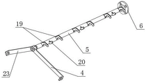
In the figure, a box body 1, an operating crank arm mechanism 2, a breaker single-stage mechanism 3, a closing operating handle 4, a crank arm 5, a shaft sleeve 6, a spring 7, a support rod boss 8, a transmission support rod 9, a permanent magnet mechanism 10, a closing crank arm support seat 11, a closing turning block 12, a closing crank arm 13, a opening crank arm 14, an opening crank arm support seat 15, a mechanism support plate 16, a protective cover 17, a limit groove 18, a closing tooth 19, a opening tooth 20, a roller 21, a opening limit groove 22, a opening operating handle 23 and a return spring 24.
Detailed Description
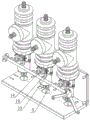
As shown in fig. 1 to 8, the 12KV circuit breaker manual switching-on and switching-off device mainly includes a box 1, an operating crank arm mechanism 2, and a three-group circuit breaker single-stage mechanism 3.
One side of the box body 1 is connected with a protective cover 17, and a closing limit groove 18 and an opening limit groove 22 are arranged on the protective cover 17.
The connecting lever mechanism 2 comprises a connecting lever 5, a shaft sleeve 6, a closing operation handle 4 and a separating operation handle 23, the connecting lever 5 is transversely supported on the box body 1, six closing teeth 19 and three separating teeth 20 are connected on the connecting lever 5, the shaft sleeve 6 is arranged at one end of the connecting lever 5 after the box body 1 is stretched out, the shaft sleeve 6 is connected with the box body 1, the closing operation handle 4 and the separating operation handle 23 are connected to the other end of the connecting lever 5, the closing operation handle 4 corresponds to the closing limiting groove 18 and is arranged, and the closing operation handle 4 rotates to the closing limiting groove 18 to be limited. The opening operating handle 23 is arranged corresponding to the opening limiting groove 22, and when the opening operating handle 23 rotates into the opening limiting groove 22, the opening is limited.
The group of circuit breaker single-stage mechanisms 3 correspond to one opening tooth 20 and two closing teeth 19, each circuit breaker single-stage mechanism 3 comprises a permanent magnet mechanism 10 and a transmission support rod 9, a mechanism supporting plate 16 is connected above the permanent magnetic mechanism 10, two closing crank arm supporting seats 11 are connected on the mechanism supporting plate 16, the automatic closing device is characterized in that a closing connecting arm 13 is arranged in each closing connecting arm supporting seat 11, the middle of each closing connecting arm 13 is hinged to the corresponding closing connecting arm supporting seat 11, each closing connecting arm supporting seat 11 is connected with the corresponding closing connecting arm 13 through a spring 7, one end of each closing connecting arm 13 is arranged under each closing tooth 19, the other end of each closing connecting arm 13 is hinged to a closing overturning block 12, each closing connecting arm 13 is connected with the corresponding closing overturning block 12 through a resetting spring 24 (shown in figure 9), each closing overturning block 12 is connected with a roller 21, a circle of supporting rod boss 8 is integrally arranged on each transmission supporting rod 9, and each roller 21 is arranged below the corresponding supporting rod boss 8.
An opening connecting lever supporting seat 15 is further connected to the mechanism supporting plate 16, the opening connecting lever supporting seat 15 is arranged between the two closing connecting lever supporting seats 11, an opening connecting lever 14 is hinged in the opening connecting lever supporting seat 15, one end of the opening connecting lever 14 is arranged right above the opening tooth 20, and the other end of the opening connecting lever 14 is U-shaped and arranged above the supporting rod boss 8.
The working principle of the invention is as follows:
firstly, a switching-on process:
firstly, when the switch is switched on, the switch operating handle 4 is pulled downwards or pressed, through transmission matching, the switch-on teeth 19 of the connecting lever 5 apply downward acting force to the switch connecting lever 13, and the support lever boss 8 of the transmission support lever 9 is pushed by the switch-on turning block 12 to carry out lifting movement.
Secondly, in the lifting process of the switch closing connecting lever 13, the supporting roller 21 in the switch closing overturning block 12 and the supporting rod boss 8 of the transmission supporting rod 9 make tangential motion, the movement crosses the zero point, and the supporting roller continues to lift, release and separate to create a brake separating space. Finally, the descending action of the operating handle 4 is limited by the closing limiting groove 18 of the protective cover 17 at the end part of the box body 1, and the circuit breaker completes the closing operation.
Secondly, a brake opening process:
firstly, when the brake is opened, the brake-opening operating handle 23 is pulled or pressed downwards, and through transmission matching, the brake-opening teeth 20 of the crank arm 5 apply upward acting force to the brake-opening crank arm 14 to push the transmission supporting rod 9 to descend to the brake-opening position. Finally, the opening limiting groove 22 of the protective cover 17 at the end part of the box body 1 limits the descending action of the opening operation handle 23, and the breaker completes opening operation.
Thirdly, resetting:
resetting the brake-separating crank arm 14: and (4) switching on, lifting the transmission support rod 9, pushing the switching-off connecting lever 14 to move upwards by the support rod boss 8, finishing the switching-on action, and returning the switching-off connecting lever 14 to the initial position.
Secondly, resetting the closing crank arm 13: and (3) switching-off operation is carried out, the transmission supporting rod 9 descends, the switching-on connecting lever 13 is lifted upwards due to the restoring tension of the spring 7, and the switching-on overturning block 12 passes through the supporting rod boss 8 and then is restored through the lower restoring spring 24. And after the switching-off action is finished, the switching-on connecting lever 13 returns to the initial position.
Claims (4)
1. The utility model provides a manual divide-shut brake device of 12KV circuit breaker, includes box and three circuit breaker single-stage mechanism of group, and circuit breaker single-stage mechanism includes permanent magnetic mechanism, transmission bracing piece, characterized by: one side of the box body is connected with a protective cover, and a closing limiting groove and a separating limiting groove are arranged on the protective cover; the box body is provided with an operating connecting lever mechanism, the operating connecting lever mechanism comprises a connecting lever, a closing operation handle and an opening operation handle, the connecting lever is supported on the box body, the closing tooth and the opening tooth are connected to the connecting lever, the closing operation handle and the opening operation handle are both connected to one end of the connecting lever, the closing operation handle and the closing limiting groove are arranged correspondingly, and the opening operation handle and the opening limiting groove are arranged correspondingly; a mechanism supporting plate is connected above the permanent magnetic mechanism, a closing connecting arm supporting seat is connected to the mechanism supporting plate, a closing connecting arm is arranged in the closing connecting arm supporting seat, the middle of the closing connecting arm is hinged to the closing connecting arm supporting seat, the closing connecting arm is connected with the closing connecting arm supporting seat through a spring, one end of the closing connecting arm is arranged right below a closing tooth, the other end of the closing connecting arm is hinged to a closing overturning block, a roller is connected in the closing overturning block, a circle of supporting rod boss is integrally arranged on the transmission supporting rod, and the roller is arranged below the supporting rod boss; still connect the separating brake connecting lever supporting seat in the mechanism backup pad, articulated separating brake connecting lever in the separating brake connecting lever supporting seat, the one end setting of separating brake connecting lever is directly over the separating brake tooth, and the other end setting of separating brake connecting lever is in the top of bracing piece boss.
2. The manual switching-on and switching-off device of the 12KV circuit breaker according to claim 1, characterized in that: each mechanism supporting plate is provided with two closing connecting lever supporting seats, two closing connecting levers, two closing turning blocks, two idler wheels and two springs, and the opening connecting lever supporting seat is arranged between the two closing connecting lever supporting seats; the circuit breaker single-stage mechanism corresponds to one opening tooth and two closing teeth, the opening tooth is arranged between the two closing teeth, and one end of each of the two closing connecting levers corresponds to the two closing teeth.
3. The manual switching-on and switching-off device of the 12KV circuit breaker according to claim 1, characterized in that: and one end of the opening crank arm facing the support boss is U-shaped.
4. The manual switching-on and switching-off device of the 12KV circuit breaker according to claim 1, characterized in that: and the closing connecting lever is connected with the closing overturning block through a resetting spring.
Priority Applications (1)
| Application Number | Priority Date | Filing Date | Title |
|---|---|---|---|
| CN202111578950.9A CN114242535A (en) | 2021-12-22 | 2021-12-22 | Manual opening and closing device of 12KV circuit breaker |
Applications Claiming Priority (1)
| Application Number | Priority Date | Filing Date | Title |
|---|---|---|---|
| CN202111578950.9A CN114242535A (en) | 2021-12-22 | 2021-12-22 | Manual opening and closing device of 12KV circuit breaker |
Publications (1)
| Publication Number | Publication Date |
|---|---|
| CN114242535A true CN114242535A (en) | 2022-03-25 |
Family
ID=80761079
Family Applications (1)
| Application Number | Title | Priority Date | Filing Date |
|---|---|---|---|
| CN202111578950.9A Pending CN114242535A (en) | 2021-12-22 | 2021-12-22 | Manual opening and closing device of 12KV circuit breaker |
Country Status (1)
| Country | Link |
|---|---|
| CN (1) | CN114242535A (en) |
Citations (6)
| Publication number | Priority date | Publication date | Assignee | Title |
|---|---|---|---|---|
| DE102012202083A1 (en) * | 2012-02-13 | 2013-08-14 | Siemens Aktiengesellschaft | Latch for electrical switching device e.g. circuit breaker, has two parallel stop surfaces arranged on latch, which are axially offset from supporting surface with respect to rotational axis, to stop rocker arm of switching device |
| CN103700549A (en) * | 2014-01-06 | 2014-04-02 | 巨邦电气集团有限公司 | Manual and electric operating mechanism of circuit breaker and reclosing circuit breaker with operating mechanism |
| CN204792595U (en) * | 2015-07-23 | 2015-11-18 | 亚洲电力设备(深圳)股份有限公司 | Permanent magnetism vacuum circuit breaker switch |
| CN106847610A (en) * | 2017-03-13 | 2017-06-13 | 张文炎 | Permanent magnetic spring actuating integral mechanism and its application method |
| CN208256602U (en) * | 2018-05-23 | 2018-12-18 | 河南森源电气股份有限公司 | Permanent-magnet breaker and its manual switching-off device |
| CN213905158U (en) * | 2020-12-22 | 2021-08-06 | 厦门华电开关有限公司 | Manual switching-on and switching-off device of circuit breaker and circuit breaker |
-
2021
- 2021-12-22 CN CN202111578950.9A patent/CN114242535A/en active Pending
Patent Citations (6)
| Publication number | Priority date | Publication date | Assignee | Title |
|---|---|---|---|---|
| DE102012202083A1 (en) * | 2012-02-13 | 2013-08-14 | Siemens Aktiengesellschaft | Latch for electrical switching device e.g. circuit breaker, has two parallel stop surfaces arranged on latch, which are axially offset from supporting surface with respect to rotational axis, to stop rocker arm of switching device |
| CN103700549A (en) * | 2014-01-06 | 2014-04-02 | 巨邦电气集团有限公司 | Manual and electric operating mechanism of circuit breaker and reclosing circuit breaker with operating mechanism |
| CN204792595U (en) * | 2015-07-23 | 2015-11-18 | 亚洲电力设备(深圳)股份有限公司 | Permanent magnetism vacuum circuit breaker switch |
| CN106847610A (en) * | 2017-03-13 | 2017-06-13 | 张文炎 | Permanent magnetic spring actuating integral mechanism and its application method |
| CN208256602U (en) * | 2018-05-23 | 2018-12-18 | 河南森源电气股份有限公司 | Permanent-magnet breaker and its manual switching-off device |
| CN213905158U (en) * | 2020-12-22 | 2021-08-06 | 厦门华电开关有限公司 | Manual switching-on and switching-off device of circuit breaker and circuit breaker |
Similar Documents
| Publication | Publication Date | Title |
|---|---|---|
| CN201364854Y (en) | Double-fracture vacuum fling-cut switch | |
| CN202034297U (en) | Outdoor high-pressure permanent-magnet vacuum circuit breaker | |
| CN201788888U (en) | Single-phase vacuum breaker with double arc-extinguishing chambers for controlling transmission mode | |
| CN205069492U (en) | Outdoor permanent magnetism vacuum circuit breaker | |
| CN2914304Y (en) | Permanent magnetism intelligent mechanism low-voltage vacuum breaker | |
| CN201084635Y (en) | A large-capacity vacuum load switch | |
| CN114242535A (en) | Manual opening and closing device of 12KV circuit breaker | |
| CN102723229B (en) | Manual operation mechanism of outdoor permanent magnetic high-voltage vacuum circuit breaker | |
| CN207217370U (en) | The rocker switch with breaking function is connected with safety | |
| CN1093329C (en) | Interlocking plug-in box for bus bar | |
| CN211628978U (en) | Modularized spring operating mechanism for outdoor high-voltage vacuum circuit breaker | |
| CN212516998U (en) | Direct control device for contact net isolating switch | |
| CN201417896Y (en) | Handcart-type 126KV composite apparatus | |
| CN207611714U (en) | Anti-mistaken interlocking device used for high-voltage switch | |
| CN105374621A (en) | Modularization spring operating mechanism for high voltage vacuum circuit breaker | |
| CN201311893Y (en) | Controlling and protecting switch electric apparatus | |
| CN201549437U (en) | Indoor fixed-sealing type permanent magnet vacuum circuit breaker | |
| CN211479967U (en) | Automatic energy storage type combined electrical apparatus | |
| CN205487932U (en) | Outdoor interchange high pressure permanent magnetism vacuum circuit breaker | |
| CN2598120Y (en) | Isolative switch mated with vacuum circuit breaker on column | |
| CN215496545U (en) | Manual brake separating device of vacuum contactor | |
| CN219476564U (en) | Indoor vacuum circuit breaker of plateau type suitable for electrified railway | |
| CN217306341U (en) | Circuit breaker zero-pressure locking opening and closing interlocking device | |
| CN213635769U (en) | Circuit breaker | |
| CN201725699U (en) | Novel circuit breaker transmission linkage mechanism |
Legal Events
| Date | Code | Title | Description |
|---|---|---|---|
| PB01 | Publication | ||
| PB01 | Publication | ||
| SE01 | Entry into force of request for substantive examination | ||
| SE01 | Entry into force of request for substantive examination |