CN1142419C - Air-pressure sensor - Google Patents
Air-pressure sensor Download PDFInfo
- Publication number
- CN1142419C CN1142419C CNB998099260A CN99809926A CN1142419C CN 1142419 C CN1142419 C CN 1142419C CN B998099260 A CNB998099260 A CN B998099260A CN 99809926 A CN99809926 A CN 99809926A CN 1142419 C CN1142419 C CN 1142419C
- Authority
- CN
- China
- Prior art keywords
- air
- bar
- limit
- pressure sensor
- mentioned
- Prior art date
- Legal status (The legal status is an assumption and is not a legal conclusion. Google has not performed a legal analysis and makes no representation as to the accuracy of the status listed.)
- Expired - Fee Related
Links
Images


Classifications
-
- G—PHYSICS
- G01—MEASURING; TESTING
- G01L—MEASURING FORCE, STRESS, TORQUE, WORK, MECHANICAL POWER, MECHANICAL EFFICIENCY, OR FLUID PRESSURE
- G01L19/00—Details of, or accessories for, apparatus for measuring steady or quasi-steady pressure of a fluent medium insofar as such details or accessories are not special to particular types of pressure gauges
-
- G—PHYSICS
- G01—MEASURING; TESTING
- G01P—MEASURING LINEAR OR ANGULAR SPEED, ACCELERATION, DECELERATION, OR SHOCK; INDICATING PRESENCE, ABSENCE, OR DIRECTION, OF MOVEMENT
- G01P13/00—Indicating or recording presence, absence, or direction, of movement
- G01P13/02—Indicating direction only, e.g. by weather vane
- G01P13/025—Indicating direction only, e.g. by weather vane indicating air data, i.e. flight variables of an aircraft, e.g. angle of attack, side slip, shear, yaw
-
- G—PHYSICS
- G01—MEASURING; TESTING
- G01P—MEASURING LINEAR OR ANGULAR SPEED, ACCELERATION, DECELERATION, OR SHOCK; INDICATING PRESENCE, ABSENCE, OR DIRECTION, OF MOVEMENT
- G01P5/00—Measuring speed of fluids, e.g. of air stream; Measuring speed of bodies relative to fluids, e.g. of ship, of aircraft
- G01P5/14—Measuring speed of fluids, e.g. of air stream; Measuring speed of bodies relative to fluids, e.g. of ship, of aircraft by measuring differences of pressure in the fluid
- G01P5/16—Measuring speed of fluids, e.g. of air stream; Measuring speed of bodies relative to fluids, e.g. of ship, of aircraft by measuring differences of pressure in the fluid using Pitot tubes, e.g. Machmeter
- G01P5/165—Arrangements or constructions of Pitot tubes
Abstract
An air-pressure head is intended for determining parameters of an air flow, flow of other gases or fluids, as well as parameters of flight of the aircraft. The air-pressure head consists of a multi-edge rod, whose edges are oriented in the rod longitudinal direction, having groups of orifices disposed between the edges on smooth lateral surfaces of the rod which are connected via pneumatic ducts to outlet nipples disposed off the air flow. Edges in the longitudinal direction are continuous and their number is n > 3. Groups of orifices are spaced from the edges at the value of a >=0.1b, where b is the distance between the edges in any cross-section of the rod. The angle between the lateral surfaces in any cross-section of the rod being gamma < 180 DEG . Sharp edges can be rounded or rendered obtuse by chamfering and also can be implemented in the form of protrusions. The rod lateral surfaces can be convex, cylindrical and tapered. The number of edges on the rod can be 4, 5 or 6. Such parameters of the air-pressure head allow: to improve accuracy of flow (flight) parameters, simplify the design and reduce its weight.
Description
The present invention relates to determining of aircraft flight parameter, other sciemtifec and technical sphere of perhaps relevant liquids and gases stream.
Gas-flow measurement is one of most significant problems in aircraft air flight mechanics and the aerodynamics.At present, that be used for measurement flight (air-flow) parameter is air-pressure sensor (APH), and it directly is contained on airframe or its other parts usually, and air-pressure sensor is measured the actual parameter near the local air flow of planar flows.The local parameter that many such APH measure air-flow generally is housed on the aircraft.Determine actual parameter according to the demarcation of carrying out in advance.Because the remarkable flying speed of flying drilling angle that enlarges and wide region (surpassing ultrasonic speed to far away) from subsonic speed slowly, flight parameter measurement to high maneuverability can aircraft be a very important job.Because altitude maneuver performance of helicopter (all around and flight up and down) and the data of utilizing the flight parameter measurement system to obtain are done the robotization flight of these patterns, this work is particularly important to helicopter.
A known air-pressure sensor comprises the shell of mast form, is provided with air admission hole along cross-sectional perimeter, and is connected (Petounin A.N. with joint by pipeline, " measure the technology and equipment of flow parameter ", Moscow machinery building publishing house, 1972, the 88-100 page or leaf, Fig. 1 .102; Glaznev V.N., Zavaroukhin S.G., " adopting of the experimental study of the cylindricality sensor of wide digital scope ", research institute of Moscow aerohydrodynamics central authorities journal, 14 4 phases of volume, nineteen eighty-three to plane and rotational symmetry eddy current).According to linking the demarcation relation of determining parameter and gaging pressure, adopt above-mentioned air-pressure sensor to measure the pressure that the air-pressure sensor windward side produces in the continuous flow district, determine flow parameter.
The APH shortcoming of the above-mentioned type is as follows:
● because known transonic speed stability phenomenon can not be measured static pressure to satisfied precision in 0.8 to 1.1 range of Mach numbers;
● in order to determine flow parameter, can not adopt and be located at the air admission hole on the leeward side in the air-pressure sensor separation bubble layer, in these holes, though be not subjected to the influence of transonic speed stability, pressure and Reynolds number, surfaceness and enter the flow perturbation degree much relations are arranged.
● also have another shortcoming, be actually the result of above shortcoming, it has obviously too much pressure measurement pipeline number, because in order to determine three parameter (stagnation pressure P
t, static pressure P
sWith angle of downwash α), this APH will establish three holes at least on the windward side in free separating layer; "ball-park" estimate has illustrated: if when determining flow parameter and keeping satisfied sensitivity in ° scope of α=0~360, at least need along equally spaced 8 or 9 air admission holes of APH cross-sectional perimeter (pitch is 45 ° or 40 °), it has caused the APH size to increase, the increase of aerodynamic drag raising, the weight of APH own and measuring equipment construction weight is because pressure transducer must be connected with each pipeline; In addition, it is more expensive that this has caused the measuring system of this APH.
Known have a kind of equipment (European patent document, publication No. 0049756B1, G01F1/46, G01L13/00, the equipment of pressure reduction " measure "; Priority number: 09.10.80 DE 3038180, holder of the patent right: IWK Regier und Kompensatoren company limited; Inventor: Fehbr, Dieter, Dr. Dipl-Phys.) is suitable for measuring pressure drop.The basic building block of this equipment is the bar of positive hexagonal prismoid shape, has a hole (the perhaps many holes that are connected with air-pressure duct) to be used for pressure survey on its each limit.When the direction of bar in air-flow makes the gas velocity vector extend through the axis of limit, bar of opening and the limit that faces toward, adopt the pressure transducer that is connected with above-mentioned hole by air-pressure duct to detect pressure near stagnation pressure.Scatter 180 the time with respect to velocity vector when the direction of bar in air-flow makes the hole on the bar, can utilize these holes to determine base pressure.Therefore, adopt such APH, can measure current rate (or stagnation pressure P according to default the demarcation
tWith static pressure P
s).Above-mentioned patent recommends to be used for the ducted P of measurement gas by two equipment that bar is formed as above-mentioned direction
tAnd P
s
But this APH or the equipment of making according to it can not really be suitable for measuring simultaneously three flow parameter (stagnation pressure P
t, static pressure P
sAnd angle of downwash (angle of attack) α), because it lacks suitable hole count, admission pressure is wanted three holes at least.In fact, known will be according to pressure P
iWith the free air angle of attack (angle of downwash) α, stagnation pressure P
tWith free air static pressure P
sBetween following predetermined relationship determine flow parameter:
P
i=f
i(α,P
t,P
s) (1)
It is measured by air-pressure sensor on i admission pressure point.For with respect to α, P
t, P
sFind the solution this system of equations, need a hole, i 〉=3, in addition, this system of equations must be fully suitable fixed.For example, be arranged in pressure balanced separating layer, then P as two hole i=1 and i=2
1≈ P
2To work in very big α scope, system of equations becomes calmly uncomfortable and can not find the solution.Therefore, when need be in ° scope of α=0~360 during the parameter of measurement plane parallel-flow, illustrated as test data analyzer, the APH body must have a hole, i 〉=4, and they will be scattered in and can realize from some hole to " conversion " in other hole.
Another shortcoming of above-mentioned prior art is that the pressure breathing hole is located on the prismatic limit.Even this has caused this APH directed a little again with respect to air-flow (as above-mentioned position), air-flow can separate from this limit.The sensitivity that this has caused loss that α is changed, promptly above-mentioned system of equations (1) intangibility that becomes.
The maximally related prior art of air-pressure sensor is the rod with equilateral triangle tee section.At the end face of bar, be provided with the superstructure of a cylindricality with the same axis of this bar, it has the side equilateral triangle tee section identical with bar cross section side, and above-mentioned triangle is with respect to angle φ=60 of rotation, bar cross section °.On the side plane of bar and superstructure, be provided with six air admission holes being connected with joint by pipeline (" air-pressure sensor ", patent No. RF N on April 8th, 1809341,1991 is priority date for Golovkin M.A., Yefremov A.A.).
The shortcoming of this APH is as follows: ● design is complicated; ● the precision of determining flight parameter is not enough, particularly when air-flow slip situation; ● too much pressure measurement pipeline number, cause APH itself and whole measuring system weight to increase.
The objective of the invention is simplified design, improve flight (air-flow) parameter measurement precision, reduce APH construction weight and whole measuring system weight.
Adopt following technology way can reach desired technical result: air-pressure sensor makes polygon rod type, the direction on limit is along the bar direction of principal axis, be provided with one group of hole on the smooth flanks of bar between each limit, the air outlet adapter outer with being located at air-flow by air-pressure duct is connected.Limit longitudinally is continuous, and its number n>3; The limit of one group of hole and the definite side a 〉=0.1b value of being separated by, b is the distance between each limit in any bar cross section here; Angle in any bar cross section between the side is γ<180 °.Simplified design thus, also improved the precision of when air-flow slides, determining flight parameter, because do not have as APH is in the situation of relevant prior art to flow out and near the division wake flow of air admission hole in two part (bar and superstructure) junction.
Adopt following setting also can reach desired technical result: but sharp edge rounding or use the chamfering rust, and above-mentioned rounding or chamfering are linking with the smooth flanks of bar on the c≤0.05b distance of two adjacent side junction.This rounding or chamfering may be exclusive technical characteristics.According to the experimental study data, in fact above-mentioned c≤0.05b value navigates to the burbling line binding district of fillet or chamfering and bar side, has guaranteed that thus measurement and Reynolds number are irrelevant.By the limit being made form at the bar upper process, in the bar cross section, measure high h≤0.1b of being and the wide e≤0.1b of being, also can reach desired technical result.Illustrated as the experimental study of having carried out, above-mentioned this shape for lugs navigates to the burbling line on the projection, and also makes measurement and Reynolds number irrelevant.In some cases, the limit of shape for lugs simplified design to a great extent.
By the bar side is that cylindricality or taper also can reach desired technical result.Simplified design thus, and its manufacturing becomes and spends less.
By the bar side between each limit is that convex also can reach desired technical result.This APH shape is allowed on the one hand and is reduced Reynolds number to tonometric influence as far as possible, has improved the sensitivity of measuring equipment on the other hand, because increased the derivative of institute's measuring pressure to angle of downwash, thereby greatly reduces measurement error value.
By selector top number be four, five or hexagon also can reach desired technical result, the number angle of attack scope required with measuring flight (air-flow) parameter in limit is relevant.Particularly, illustrated as the test of having carried out, when doing to measure in ° scope of-90 °<α<90, it is enough adopting four side rods, because always can select to α P at the APH windward side on bar
t, P
sChanging two enough responsive pressure (is P
1And P
2), and in the leeward bottom side of APH a desirable pressure (P
3).Then, illustrated as the test of having carried out, above-mentioned system of equations (1) can be with respect to α, P
t, P
sFind the solution, can reduce the number of required pressure measurement pipeline thus, thereby reduce the weight of APH itself and whole measuring system.When will to measure the required angle of attack scope of flight (air-flow) parameter be α=0~360 °, illustrated as test figure, adopt five limits or hexagon bar.
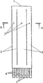
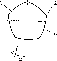
Fig. 1-3 and 4-6 have represented two embodiment of air-pressure sensor of the present invention.
Fig. 7-10 has represented the embodiment of APH of the present invention, and wherein the limit is (a) rounding (Fig. 8), and perhaps (b) uses chamfering rust (Fig. 9).
Figure 11-19 has represented the embodiment of APH of the present invention, and wherein the limit makes the form at the bar upper process.
Figure 20-22 and 23-25 have represented the embodiment of APH of the present invention, have the bar side of cylindricality and taper respectively.
Figure 26-28,29-31 and 32-34 have represented the embodiment of APH of the present invention, its king-rod has four, five and six limits respectively.
Figure 35 has represented to embody the optimal mode of rod-type APH of the present invention, and bar has the tapered side surface of plane composition and the cross section of regular polygon, and has represented to adopt the example of recommending APH in determining flight (air-flow) parameter equipment.
Figure 36 represented with respect to air-flow slide angle β=0 and β=30 °, when downwash angle α when 0 changes to 180 °, recommend the pressure ratio Cp=(P-P of APH embodiment optimal mode and prototype APH
s(wherein P is one of the APH superstructure side of maximally related prior art or recommends one of APH bar side to go up detected pressure)/q; P
sBe static pressure, q is dynamic pressure) change.This figure has adopted following symbol:
The APH of the maximally related prior art of A-in β=0 o'clock;
B-is some recommendation APH embodiment optimal mode in β=0;
The APH of relevant prior art of C-during in β=30 °;
D-recommends APH embodiment optimal mode during in β=30 °.
Figure 37 and 38 has represented to adopt and has recommended the APH embodiment optimal mode (curve D) and the APH (curve C) of relevant prior art, composition error Δ α in determining angle of downwash α and speed V and the example of Δ V, it is to determine according to the test figure under ° slow gas velocity V=15m/s of value β=30.
Figure 39 and 40 has represented to adopt recommendation APH embodiment optimal mode (curve B) and prototype APH (curve A), measuring error Δ α and Δ V in determining angle of downwash α and speed V, pressure measurement errors is the 0.5mm water column, and it is to determine according to the test figure under ° slow gas velocity V=15m/s of value β=30.
Air-pressure sensor comprises polygon bar 1, and its limit 2 directions are vertical along bar 1, and one group of hole 3 is arranged between each limit 2, is connected with joint 5 by air-pressure duct 4.Limit 2 longitudinally is continuous, and its number is n>3; One group of hole 3 is on the smooth flanks 6 that is arranged on bar 1 between the limit 2, and with the limit 2 a 〉=0.1b value of being separated by, b is the distance between each limit in any bar cross section here; Angle in any bar cross section between the side is γ<180 °.But recommend sharp edge 2 roundings among the APH or use the chamfering rust, above-mentioned rounding or chamfering from two on side junction c≤0.05b distance with smooth flanks 6 bindings of bar 1.Limit 2 can make the form at bar 1 upper process, measures high be h≤0.1b and the wide e≤0.1b of being in the bar cross section.The side 6 of bar can be cylindricality, taper or convex.Bar top 2 numbers can change according to the regulation work that will finish, are four, five or six; The bar cross section does not need complete circle.
Recommend the operation of air-pressure sensor as follows.Transmit and measured by air admission hole 3 detected pressure by measurement mechanism by air-pressure duct 4, measurement mechanism is the pressure transducer 7 (Figure 35) that is connected with joint 5 by air-pressure duct 8.According to measured force value, utilize the demarcation that is stored in advance in the device 9 with form or functional form to concern computer installation 9 calculated gas flow parameter value: α, P
t, P
sDemarcate and during the calculated gas flow parameter, utilize detected pressure in three groups of air admission holes default: two holes at leeward side, promptly are expressed as the zone of " a " and " b " in windward side and a hole among Figure 36.More detected force value arithmetic mode selecting hole group, and consider that air admission hole is corresponding to maximum pressure value down with the wind.
According to the setting of recommending APH, wherein limit longitudinally is continuous, and the bar side that is provided with air admission hole between each limit is level and smooth, recommends APH not have as in the APH prototype situation division wake flow in the outflow of two part (bar and superstructure) junction when existing air-flow to slide.Therefore error delta α and Δ V (Figure 37,38) in definite angle of downwash α and speed V when existing air-flow to slide have been reduced.
Owing to recommend the limit among the APH to count n>3, thus recommend APH facing the wind pressure ratio on the side to the derivative value α C/ δ α of angle of downwash than big (Figure 36) of the APH (n=3) of relevant prior art.When the side between each limit was convex, derivative value α C/ δ α still had bigger value.Therefore, the measuring error Δ α magnitude in determine recommending the angle of downwash of air-pressure sensor is approximately than the little twice of APH of relevant prior art, at the measuring error Δ V magnitude of determining velocity amplitude and the APH consistent (Figure 39,40) of relevant prior art.
Because recommending APH is a bar, and the APH of relevant prior art comes down to a set composite, comprises a bar and a superstructure, has therefore simplified the design of air-pressure sensor to a great extent.Recommending to adopt the limit that makes the projection form on the APH, and when the bar side of recommendation APH is cylindricality or taper, but also simplified design.Design not only becomes simpler thus, and its manufacturing becomes and spends less.
For example, select to recommend APH to have four edges to required-90 °<α<90 ° scope, when perhaps selecting to recommend APH to have five limits to α=0~360 ° scope, with the APH of the most relevant prior art relatively, can reduce required measuring channel number, in the four side rod situations of recommending APH is 2 pipelines, is 1 pipeline in the five side rod situations of recommending APH.Thus, owing to the minimizing of required pressure transducer number, can obviously reduce the weight of APH itself and whole measuring system.
Therefore, adopt to recommend air-pressure sensor can so that: simplified design, improve the precision of air-flow (flight) parameter measurement, and also reduce the weight of APH itself and whole measuring system.All these characteristics have all strengthened the competitive power of recommending APH to a great extent.
Claims (9)
1. air-pressure sensor that is used for determining flow parameter, it comprises a polygon bar, and above-mentioned bar has level and smooth side, forms a plurality of pressure channels on this side, and a plurality of air outlet adapters are linked on this pressure channel; Above-mentioned bar has the limit on it is vertical, and above-mentioned bar is provided with one group of hole on the smooth flanks of bar between each limit, and the air outlet adapter outer with being located at air-flow by pressure channel is connected, and above-mentioned air outlet adapter is linked on the pressure transducer again,
It is characterized in that bar limit longitudinally is continuous, number n>3 on limit; And one group of hole and the limit of the determining above-mentioned side a 〉=0.1b value of being separated by, b is the distance between each limit in any bar cross section here; Angle in any bar cross section between the side is γ<180 °.
2. as the air-pressure sensor in the claim 1, it is characterized in that sharp edge is a rounding and with the limit of chamfering rust, the limit of above-mentioned rounding or chamfering is linking with the smooth flanks of bar on the c≤0.05b distance of two adjacent side junction.
3. as the air-pressure sensor in the claim 1, it is characterized in that above-mentioned limit is the form at the bar upper process, this projection is measured high be h≤0.1b and the wide e≤0.1b of being in the bar cross section.
4. as 1 air-pressure sensor in the claim, it is characterized in that above-mentioned bar side is a cylindricality.
5. air-pressure sensor as claimed in claim 1 is characterized in that above-mentioned bar side is taper.
6. as 1 air-pressure sensor in the claim, it is characterized in that above-mentioned bar side is a convex.
7. as 1 air-pressure sensor in the claim, the number that it is characterized in that above-mentioned bar top is four.
8. air-pressure sensor as claimed in claim 1, the number that it is characterized in that above-mentioned bar top is five.
9. air-pressure sensor as claimed in claim 1, the number that it is characterized in that above-mentioned bar top is six.
Applications Claiming Priority (2)
| Application Number | Priority Date | Filing Date | Title |
|---|---|---|---|
| RU98112519 | 1998-07-06 | ||
| RU98112519A RU2135971C1 (en) | 1998-07-06 | 1998-07-06 | Air pressure transducer |
Publications (2)
| Publication Number | Publication Date |
|---|---|
| CN1314995A CN1314995A (en) | 2001-09-26 |
| CN1142419C true CN1142419C (en) | 2004-03-17 |
Family
ID=20207878
Family Applications (1)
| Application Number | Title | Priority Date | Filing Date |
|---|---|---|---|
| CNB998099260A Expired - Fee Related CN1142419C (en) | 1998-07-06 | 1999-07-05 | Air-pressure sensor |
Country Status (10)
| Country | Link |
|---|---|
| US (1) | US6557423B1 (en) |
| EP (1) | EP1103803B1 (en) |
| JP (1) | JP2002521648A (en) |
| KR (1) | KR100588006B1 (en) |
| CN (1) | CN1142419C (en) |
| AT (1) | ATE329270T1 (en) |
| CA (1) | CA2336765C (en) |
| DE (1) | DE69931790T2 (en) |
| RU (1) | RU2135971C1 (en) |
| WO (1) | WO2000002026A2 (en) |
Cited By (1)
| Publication number | Priority date | Publication date | Assignee | Title |
|---|---|---|---|---|
| RU213974U1 (en) * | 2022-04-26 | 2022-10-06 | Акционерное общество "Аэроприбор-Восход" | Air pressure receiver |
Families Citing this family (18)
| Publication number | Priority date | Publication date | Assignee | Title |
|---|---|---|---|---|
| CN100567909C (en) * | 2005-01-26 | 2009-12-09 | 西斯泰克控制测量及工程股份有限公司 | Dynamic pressure probe |
| US7363809B2 (en) * | 2005-07-29 | 2008-04-29 | Honeywell International Inc. | Methods and systems for providing air data parameters using mass flow and pressure sensors |
| RU2290646C1 (en) * | 2005-08-26 | 2006-12-27 | Федеральное государственное унитарное предприятие "Центральный аэрогидродинамический институт им. проф. Н.Е. Жуковского" (ФГУП "ЦАГИ") | Flight measuring air parameters system |
| US7389686B2 (en) * | 2006-03-22 | 2008-06-24 | Honeywell International Inc. | Methods and systems for determining air data parameters |
| DE102006058301B4 (en) * | 2006-12-11 | 2016-12-29 | Robert Bosch Gmbh | Air pressure sensor for side impact detection |
| US7392710B1 (en) | 2007-01-09 | 2008-07-01 | King Fahd University Of Petroleum And Minerals | Flow meter probe with force sensors |
| FR2983965B1 (en) * | 2011-12-12 | 2014-07-04 | Thales Sa | LOCAL IMPACT MEASUREMENT PROBE AND METHOD USING THE SENSOR |
| US9229458B2 (en) * | 2012-10-01 | 2016-01-05 | Emerson Process Management Regulator Technologies, Inc. | Dynamic pressure registration device for internally registered actuators and over pressure protection devices |
| RU2542791C1 (en) * | 2013-08-29 | 2015-02-27 | Федеральное государственное унитарное предприятие "Центральный аэрогидродинамический институт имени профессора Н.Е. Жуковского" (ФГУП "ЦАГИ") | Air pressure intake |
| CN106443057A (en) * | 2016-09-19 | 2017-02-22 | 王华锋 | Flow velocity pressure-sensing quantitative measuring instrument |
| CN109900919B (en) * | 2019-03-13 | 2021-03-23 | 北京强度环境研究所 | Columnar vortex-induced velocity and vibration measurement sensor |
| US10884015B2 (en) | 2019-05-01 | 2021-01-05 | Bell Textron Inc. | Multidirectional airspeed detection system |
| CN110988386A (en) * | 2019-12-12 | 2020-04-10 | 石家庄铁道大学 | Wind speed and direction testing device and testing method |
| CN111398624B (en) * | 2020-03-06 | 2022-05-27 | 清远市智慧农业研究院 | Device and method for testing penetrability of canopy of lower washing wind field |
| US11555825B1 (en) | 2020-11-24 | 2023-01-17 | Sentera, Inc. | Pitot probe assembly with replaceable tip and damping |
| EP4124867A1 (en) * | 2021-07-29 | 2023-02-01 | Rockwell Collins, Inc. | Differential pressure angle of attack sensor |
| US11579163B1 (en) | 2021-07-29 | 2023-02-14 | Rockwell Collins, Inc. | Differential pressure angle of attack sensor |
| CN114324970B (en) * | 2021-12-17 | 2023-01-10 | 华南农业大学 | Array type self-adaptive wind direction and wind speed measuring device and method |
Family Cites Families (10)
| Publication number | Priority date | Publication date | Assignee | Title |
|---|---|---|---|---|
| US3673866A (en) * | 1970-01-15 | 1972-07-04 | Viktor Borisovich Alperovich | Pitot tube probe for taking total head and static pressure of air flow |
| DE3038180A1 (en) | 1980-10-09 | 1982-05-27 | IWK Regler und Kompensatoren GmbH, 7513 Stutensee | DEVICE FOR MEASURING DIFFERENTIAL PRESSURE |
| JPS5830673A (en) * | 1981-08-18 | 1983-02-23 | Natl Aerospace Lab | Pyramidal trapesoid shaped 4-hole pitot tube type probe |
| DE3512960A1 (en) * | 1985-04-11 | 1986-10-16 | Intra-Automation GmbH Meß- und Regelinstrumente, 4053 Jüchen | DIFFERENTIAL PRESSURE FLOW PROBE |
| DE3923753A1 (en) * | 1989-07-18 | 1991-01-31 | Nord Micro Elektronik Feinmech | PROBE AND METHOD FOR MEASURING THE RELATIVE SPEED OF A FLOWING MEDIUM |
| JP2913005B2 (en) * | 1992-04-06 | 1999-06-28 | 科学技術庁航空宇宙技術研究所長 | Flight velocity vector detection system using a truncated polygonal pitot tube probe and a truncated polygonal pitot tube probe |
| US5543183A (en) * | 1995-02-17 | 1996-08-06 | General Atomics | Chromium surface treatment of nickel-based substrates |
| RU2115102C1 (en) * | 1996-08-12 | 1998-07-10 | Центральный аэрогидродинамический институт им.проф.Н.Е.Жуковского | Pitot-static tube |
| DE19640606C1 (en) * | 1996-10-01 | 1997-09-11 | Nord Micro Elektronik Feinmech | Pressure measuring device for missile |
| RU2121667C1 (en) * | 1997-01-28 | 1998-11-10 | Центральный аэрогидродинамический институт им.проф.Н.Е.Жуковского | Pitot-static tube |
-
1998
- 1998-07-06 RU RU98112519A patent/RU2135971C1/en not_active IP Right Cessation
-
1999
- 1999-07-05 AT AT99935199T patent/ATE329270T1/en not_active IP Right Cessation
- 1999-07-05 US US09/743,278 patent/US6557423B1/en not_active Expired - Fee Related
- 1999-07-05 CA CA002336765A patent/CA2336765C/en not_active Expired - Fee Related
- 1999-07-05 KR KR1020017000183A patent/KR100588006B1/en not_active IP Right Cessation
- 1999-07-05 EP EP99935199A patent/EP1103803B1/en not_active Expired - Lifetime
- 1999-07-05 JP JP2000558371A patent/JP2002521648A/en active Pending
- 1999-07-05 CN CNB998099260A patent/CN1142419C/en not_active Expired - Fee Related
- 1999-07-05 WO PCT/RU1999/000220 patent/WO2000002026A2/en active IP Right Grant
- 1999-07-05 DE DE69931790T patent/DE69931790T2/en not_active Expired - Fee Related
Cited By (1)
| Publication number | Priority date | Publication date | Assignee | Title |
|---|---|---|---|---|
| RU213974U1 (en) * | 2022-04-26 | 2022-10-06 | Акционерное общество "Аэроприбор-Восход" | Air pressure receiver |
Also Published As
| Publication number | Publication date |
|---|---|
| EP1103803A4 (en) | 2003-04-23 |
| ATE329270T1 (en) | 2006-06-15 |
| RU2135971C1 (en) | 1999-08-27 |
| CA2336765A1 (en) | 2000-01-13 |
| US6557423B1 (en) | 2003-05-06 |
| CN1314995A (en) | 2001-09-26 |
| WO2000002026A2 (en) | 2000-01-13 |
| DE69931790T2 (en) | 2007-05-16 |
| KR20010071755A (en) | 2001-07-31 |
| DE69931790D1 (en) | 2006-07-20 |
| JP2002521648A (en) | 2002-07-16 |
| EP1103803A2 (en) | 2001-05-30 |
| EP1103803B1 (en) | 2006-06-07 |
| CA2336765C (en) | 2009-05-26 |
| WO2000002026A3 (en) | 2000-05-04 |
| KR100588006B1 (en) | 2006-06-08 |
Similar Documents
| Publication | Publication Date | Title |
|---|---|---|
| CN1142419C (en) | Air-pressure sensor | |
| EP0167585B1 (en) | Pressure sensing instrument for aircraft | |
| CN103630289A (en) | Moisture resistant air data probes | |
| EP1748298B1 (en) | Methods And Systems For Providing Air Data Parameters Using Mass Flow And Pressure Sensors | |
| US20070251313A1 (en) | Methods and system for determining angles of attack and sideslip using flow sensors | |
| Schubauer et al. | The effect of turbulence on the drag of flat plates | |
| REYNOLDS et al. | Three-dimensional vortex development breakdown, and control | |
| Breitsamter et al. | Turbulent flow structure associated with vortex-induced fin buffeting | |
| RU2115102C1 (en) | Pitot-static tube | |
| Campos | On the influence of atmospheric disturbances on aircraft aerodynamics | |
| EP3179253B1 (en) | Air data probe with elliptical cross section | |
| Fisher et al. | Controlling forebody asymmetries in flight-experience with boundary layer transition strips | |
| RU2121667C1 (en) | Pitot-static tube | |
| Nebbeling et al. | Experimental investigation of the supersonic flow past a slender cone at high incidence | |
| House et al. | Wind-tunnel Investigation of Effect of Interference on Lateral-stability Characteristics of Four NACA 23012 Wings an Elliptical and a Circular Fuselage and Vertical Fins | |
| RU2260780C2 (en) | Air pressure transducer | |
| RU2257555C2 (en) | Pressure receiver | |
| RU2171456C1 (en) | Pressure transducer | |
| SMITH et al. | Laser velocimetry measurements of supersonic vortex flows on a simple razor-edged delta wing | |
| RU2237877C1 (en) | Pressure pick-up | |
| RU2237876C1 (en) | Pressure pick-up | |
| Schmidt et al. | Lift enhancement using a close-coupled oscillating canard | |
| GRIFFIN et al. | Wake characteristics and interactions of the canard/wing lifting surface configuration of the X-29 forward-swept wing flight demonstrator | |
| Bridges | Tip effects on the vortex wake of an axisymmetric body at angle of attack | |
| RU2165603C1 (en) | Pressure pick-up |
Legal Events
| Date | Code | Title | Description |
|---|---|---|---|
| C06 | Publication | ||
| C10 | Entry into substantive examination | ||
| PB01 | Publication | ||
| SE01 | Entry into force of request for substantive examination | ||
| C14 | Grant of patent or utility model | ||
| GR01 | Patent grant | ||
| C17 | Cessation of patent right | ||
| CF01 | Termination of patent right due to non-payment of annual fee |
Granted publication date: 20040317 Termination date: 20100705 |