CN114229559A - Fixed-length cutting device for cloth production - Google Patents

Fixed-length cutting device for cloth production Download PDF

Info

Publication number
CN114229559A
CN114229559A CN202010940650.XA CN202010940650A CN114229559A CN 114229559 A CN114229559 A CN 114229559A CN 202010940650 A CN202010940650 A CN 202010940650A CN 114229559 A CN114229559 A CN 114229559A
Authority
CN
China
Prior art keywords
cloth
cutting
fixed
bottom plate
block
Prior art date
Legal status (The legal status is an assumption and is not a legal conclusion. Google has not performed a legal analysis and makes no representation as to the accuracy of the status listed.)
Granted
Application number
CN202010940650.XA
Other languages
Chinese (zh)
Other versions
CN114229559B (en
Inventor
施哲峰
Current Assignee (The listed assignees may be inaccurate. Google has not performed a legal analysis and makes no representation or warranty as to the accuracy of the list.)
Anhui Youyou Fashion Technology Co ltd
Original Assignee
Anhui Youyou Fashion Technology Co ltd
Priority date (The priority date is an assumption and is not a legal conclusion. Google has not performed a legal analysis and makes no representation as to the accuracy of the date listed.)
Filing date
Publication date
Application filed by Anhui Youyou Fashion Technology Co ltd filed Critical Anhui Youyou Fashion Technology Co ltd
Priority to CN202010940650.XA priority Critical patent/CN114229559B/en
Publication of CN114229559A publication Critical patent/CN114229559A/en
Application granted granted Critical
Publication of CN114229559B publication Critical patent/CN114229559B/en
Active legal-status Critical Current
Anticipated expiration legal-status Critical

Links

Images

Classifications

    • B—PERFORMING OPERATIONS; TRANSPORTING
    • B65—CONVEYING; PACKING; STORING; HANDLING THIN OR FILAMENTARY MATERIAL
    • B65H—HANDLING THIN OR FILAMENTARY MATERIAL, e.g. SHEETS, WEBS, CABLES
    • B65H20/00—Advancing webs
    • B65H20/02—Advancing webs by friction roller
    • B—PERFORMING OPERATIONS; TRANSPORTING
    • B65—CONVEYING; PACKING; STORING; HANDLING THIN OR FILAMENTARY MATERIAL
    • B65H—HANDLING THIN OR FILAMENTARY MATERIAL, e.g. SHEETS, WEBS, CABLES
    • B65H18/00—Winding webs
    • B65H18/02—Supporting web roll
    • B65H18/028—Both ends type
    • B—PERFORMING OPERATIONS; TRANSPORTING
    • B65—CONVEYING; PACKING; STORING; HANDLING THIN OR FILAMENTARY MATERIAL
    • B65H—HANDLING THIN OR FILAMENTARY MATERIAL, e.g. SHEETS, WEBS, CABLES
    • B65H19/00—Changing the web roll
    • B65H19/22—Changing the web roll in winding mechanisms or in connection with winding operations
    • B65H19/30—Lifting, transporting, or removing the web roll; Inserting core
    • B—PERFORMING OPERATIONS; TRANSPORTING
    • B65—CONVEYING; PACKING; STORING; HANDLING THIN OR FILAMENTARY MATERIAL
    • B65H—HANDLING THIN OR FILAMENTARY MATERIAL, e.g. SHEETS, WEBS, CABLES
    • B65H23/00—Registering, tensioning, smoothing or guiding webs
    • B65H23/04—Registering, tensioning, smoothing or guiding webs longitudinally
    • B65H23/26—Registering, tensioning, smoothing or guiding webs longitudinally by transverse stationary or adjustable bars or rollers
    • B—PERFORMING OPERATIONS; TRANSPORTING
    • B65—CONVEYING; PACKING; STORING; HANDLING THIN OR FILAMENTARY MATERIAL
    • B65H—HANDLING THIN OR FILAMENTARY MATERIAL, e.g. SHEETS, WEBS, CABLES
    • B65H35/00—Delivering articles from cutting or line-perforating machines; Article or web delivery apparatus incorporating cutting or line-perforating devices, e.g. adhesive tape dispensers
    • B65H35/04—Delivering articles from cutting or line-perforating machines; Article or web delivery apparatus incorporating cutting or line-perforating devices, e.g. adhesive tape dispensers from or with transverse cutters or perforators
    • B65H35/06—Delivering articles from cutting or line-perforating machines; Article or web delivery apparatus incorporating cutting or line-perforating devices, e.g. adhesive tape dispensers from or with transverse cutters or perforators from or with blade, e.g. shear-blade, cutters or perforators
    • D—TEXTILES; PAPER
    • D06—TREATMENT OF TEXTILES OR THE LIKE; LAUNDERING; FLEXIBLE MATERIALS NOT OTHERWISE PROVIDED FOR
    • D06H—MARKING, INSPECTING, SEAMING OR SEVERING TEXTILE MATERIALS
    • D06H7/00—Apparatus or processes for cutting, or otherwise severing, specially adapted for the cutting, or otherwise severing, of textile materials
    • D06H7/02—Apparatus or processes for cutting, or otherwise severing, specially adapted for the cutting, or otherwise severing, of textile materials transversely
    • B—PERFORMING OPERATIONS; TRANSPORTING
    • B65—CONVEYING; PACKING; STORING; HANDLING THIN OR FILAMENTARY MATERIAL
    • B65H—HANDLING THIN OR FILAMENTARY MATERIAL, e.g. SHEETS, WEBS, CABLES
    • B65H2701/00—Handled material; Storage means
    • B65H2701/10—Handled articles or webs
    • B65H2701/11—Dimensional aspect of article or web
    • B65H2701/113—Size
    • B65H2701/1133—Size of webs

Landscapes

  • Engineering & Computer Science (AREA)
  • Textile Engineering (AREA)
  • Treatment Of Fiber Materials (AREA)

Abstract

本发明公开了一种布匹生产定长裁剪装置,包括底板和布匹,底板的上表面靠近左端设置有送料辊,且位于送料辊的右侧设置有裁剪机构,通过设置的两个反向转动的辊轴构成的送料辊对纺织出来的布匹进行牵引送料,并通过设置的裁剪机构和下裁剪块的相互配合实现对布匹定长裁断,并通过导料辊对裁断后的布匹进行导向输送,在通过设置的卷料机构对布匹进行收卷,使得布匹的裁剪效率更高,并且通过设置的能够转动的转动杆方便将其转动打开将卷料的卷筒套在上边然后将转动杆进行复位卡装则可实现对布匹的收卷,使得布匹收卷时的卷筒安装和卷好布匹的料卷取下更加的方便快捷。

Figure 202010940650

The invention discloses a fixed-length cutting device for cloth production, comprising a bottom plate and cloth. A feeding roller is arranged on the upper surface of the bottom plate near the left end, and a cutting mechanism is arranged on the right side of the feeding roller. The feeding roller formed by the roller shaft pulls and feeds the woven cloth, and the cloth is cut to a fixed length through the cooperation of the set cutting mechanism and the lower cutting block, and the cut cloth is guided and conveyed by the guide roller. The cloth is wound through the set reeling mechanism, so that the cutting efficiency of the cloth is higher, and it is convenient to rotate and open through the set rotatable rotating rod, put the roll of the coiled material on the top, and then reset the rotating rod. The installation can realize the winding of the cloth, which makes the installation of the roll during the winding of the cloth and the removal of the roll of the rolled cloth more convenient and quick.

Figure 202010940650

Description

Fixed-length cutting device for cloth production
Technical Field
The invention relates to the technical field of cloth production, in particular to a fixed-length cutting device for cloth production.
Background
Cloth is the fabric, "piece" originally is the ancient measurement unit of china, and 1 piece is 4 and builds, also 13.2 meters, and ancient people is used for measuring not thin clothing mostly, and the cloth is called to show the dress fabric of preparation clothing closely, and there are various materials such as dacron, cotton, numb, silk in the modern times, and various cloth that use in the life all cut out through cloth and form, and cloth often need cut out the cloth that the weaving comes out to the fixed length when production and then will cut out the cloth and carry out the rolling realization cloth's production and processing.
The applicant of the invention finds that the taking of the cut cloth is inconvenient when the cloth is rolled in the production of the existing cloth, and the cutting efficiency of the cloth is not high.
Disclosure of Invention
The invention aims to provide a fixed-length cutting device for cloth production, and aims to solve the problems that the conventional cloth production is inconvenient in taking materials when the cloth is rolled after being cut, and the cutting efficiency of the cloth is low.
The invention is realized by the following steps:
a fixed-length cutting device for cloth production comprises a bottom plate and cloth, wherein a feeding roller is arranged on the upper surface of the bottom plate close to the left end, a cutting mechanism is arranged on the right side of the feeding roller, a lower cutting block is arranged on the upper surface of the bottom plate under the cutting mechanism, two material guide rollers are arranged on the right side of the cutting mechanism, material guide frames are arranged between the two material guide rollers and on the right side of the material guide rollers, a material rolling mechanism is arranged on the upper surface of the bottom plate close to the right end, the right end of the cloth sequentially penetrates through the feeding roller, the cutting mechanism, the material guide rollers and the material rolling mechanism, supporting legs are arranged on the lower surface of the bottom plate, a traveling mechanism capable of being adjusted in a lifting mode is arranged on the lower surface of the bottom plate close to the left end and the right end, the material rolling mechanism comprises a rotating rod, the front end of the rotating rod is rotatably fixed on the rotating block, a rotating shaft is arranged at the lower end of the rotating block and is rotatably fixed on a fixed block through the rotating shaft, the fixed block is fixed on the bottom plate, the front end of the rotating rod is clamped in the hanging groove on the hanging plate, the hanging plate is provided with a locking block for limiting and blocking the rotating rod, the hanging plate is fixed on the bottom plate, the rotating rod is sleeved with a winding drum for winding cloth, the woven cloth is drawn and fed by a feeding roller consisting of two roller shafts which rotate reversely, the fixed-length cutting of the cloth is realized through the mutual matching of the arranged cutting mechanism and the lower cutting block, and the cut cloth is guided and conveyed through the guide roller, the cloth is rolled up by the arranged rolling mechanism, so that the cloth cutting efficiency is higher, the cloth can be rolled up by conveniently rotating and opening the rotary rod through the rotary rod which can rotate to sleeve the winding drum of the rolled material on the upper edge and then resetting and clamping the rotary rod, the winding drum can be mounted when the cloth is wound and the material roll with the cloth wound is taken down more conveniently and quickly.
Further, the upper surface of the lower cutting block is provided with a clamping groove, the insert is clamped on the inner side of the clamping groove, the upper surface of the insert is provided with a cutting groove, downward convex fixing edges are arranged at the front end and the rear end of the lower surface of the insert, guide edges are arranged at the left end and the right end of the lower cutting block, independent replacement can be achieved through the arranged insert, and cutting of cloth is achieved through the matching of the arranged cutting groove and the cutting mechanism.
Further, the cutting mechanism comprises a front vertical rod and a rear vertical rod which are fixed on the bottom plate, a supporting plate is arranged between the two vertical rods and close to the upper end, a guide block is arranged below the supporting plate between the two vertical rods, two cylinders are fixedly arranged on the upper surface of the supporting plate, ejector rods of the two cylinders penetrate through the supporting plate and are fixedly connected with cutters which are inserted on the guide block, the cutters are pressed downwards to be cut through the ejector rods of the cylinders, and the cutters are guided through the guide block.
Further, the cutter includes cutting board and cutting edge, and the lower extreme of cutting board is provided with the catching groove, and the upper end of cutting edge is provided with the dop with catching groove complex, and the upper end of cutting edge still is provided with the plug of inserting on the cutting board, directly changes it when convenient to the cutter maintenance through the cutting edge that sets up, reduces cost of maintenance.
Further, the guide frame is including fixing the riser on the bottom plate, and the fixed stock guide that is provided with in upper end of riser, through the direction when the stock guide flows cloth.
Furthermore, the walking mechanism comprises two vertical support rods which downwards penetrate through the bottom plate, the lower ends of the two support rods are fixedly provided with idler wheels, the upper ends of the two support rods are fixedly connected through a connecting rod, an inverted U-shaped fixing frame fixed on the bottom plate is arranged in the middle of the connecting rod, an adjusting screw for tightly pushing the connecting rod is screwed at the upper end of the fixing frame, and the idler wheels are enabled to land and support to realize position movement adjustment of the whole device by screwing the adjusting screw to push the support rods to move downwards.
Compared with the prior art, the invention has the beneficial effects that:
according to the cloth cutting device, the feeding roller consisting of the two reversely rotating roller shafts is used for drawing and feeding woven cloth, the fixed-length cutting of the cloth is realized through the mutual matching of the arranged cutting mechanism and the lower cutting block, the cut cloth is guided and conveyed through the guide roller, the cloth is wound through the arranged winding mechanism, the cutting efficiency of the cloth is higher, the rotating rod capable of rotating is convenient to rotate, the winding drum of the wound cloth is sleeved on the upper side of the winding drum, and then the rotating rod is reset and clamped, so that the winding of the cloth can be realized, and the winding drum installation during the winding of the cloth and the winding of the wound cloth are more convenient and rapid.
Drawings
In order to more clearly illustrate the technical solutions of the embodiments of the present invention, the drawings that are required to be used in the embodiments will be briefly described below, it should be understood that the following drawings only illustrate some embodiments of the present invention and therefore should not be considered as limiting the scope, and for those skilled in the art, other related drawings can be obtained according to the drawings without inventive efforts.
FIG. 1 is a perspective view of a length-fixed cutting apparatus for use in the manufacture of cloth in accordance with the present invention;
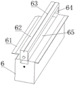
FIG. 2 is a schematic view of a lower cutting block of a web production cut-to-length apparatus of the present invention;
FIG. 3 is a schematic view of a cutting mechanism of a device for fixed length cutting in cloth production of the present invention;
FIG. 4 is a schematic view of a cutting blade of a device for cut-to-length production of cloth in accordance with the present invention;
FIG. 5 is a schematic view of a take-up mechanism of a length-fixed cutting apparatus for use in cloth production according to the present invention;
FIG. 6 is a schematic view of a material guiding frame of the device for cutting a piece of cloth to a fixed length according to the present invention;
fig. 7 is a schematic view of a running gear of the cloth production cut-to-length device of the present invention.
In the figure: 1. a cutting mechanism; 110. a cylinder; 120. a support plate; 130. a cutter; 131. a cutting board; 132. buckling grooves; 133. a blade; 134. clamping a head; 135. a plug; 140. a guide block; 150. a vertical rod; 2. a feed roller; 3. a base plate; 4. cloth; 5. a material rolling mechanism; 51. a locking block; 52. hanging the plate; 53. hanging a groove; 54. rotating the rod; 55. a reel; 56. rotating the block; 57. a rotating shaft; 58. a fixed block; 6. a lower cutting block; 61. material guiding edges; 62. an insert; 63. grooving; 64. fixing the edge; 65. a card slot; 7. a material guide roller; 8. a material guide frame; 81. a vertical plate; 82. a material guide plate; 9. a support leg; 10. a traveling mechanism; 101. a fixed mount; 102. adjusting screws; 103. a connecting rod; 104. a support bar; 105. and a roller.
Detailed Description
In order to make the objects, technical solutions and advantages of the embodiments of the present invention more apparent, the technical solutions of the embodiments of the present invention will be described clearly and completely with reference to the accompanying drawings of the embodiments of the present invention, and it is obvious that the described embodiments are some, but not all embodiments of the present invention. All other embodiments, which can be obtained by a person skilled in the art without any inventive step based on the embodiments of the present invention, are within the scope of the present invention. Thus, the following detailed description of the embodiments of the present invention, presented in the figures, is not intended to limit the scope of the invention, as claimed, but is merely representative of selected embodiments of the invention.
Embodiment 1, please refer to fig. 1 and 5 specifically, a cloth production fixed length cutting device comprises a bottom plate 3 and a cloth 4, a feeding roller 2 is arranged on the upper surface of the bottom plate 3 near the left end, a cutting mechanism 1 is arranged on the right side of the feeding roller 2, a lower cutting block 6 is arranged on the upper surface of the bottom plate 3 under the cutting mechanism 1, two material guiding rollers 7 are arranged on the right side of the cutting mechanism 1, material guiding frames 8 are arranged between the two material guiding rollers 7 and on the right side of the material guiding rollers 7, a winding mechanism 5 is arranged on the upper surface of the bottom plate 3 near the right end, the right end of the cloth 4 sequentially passes through the feeding roller 2, the cutting mechanism 1, the material guiding rollers 7 and the winding mechanism 5, supporting legs 9 are arranged on the lower surface of the bottom plate 3, traveling mechanisms 10 capable of performing lifting adjustment are arranged on the lower surface of the bottom plate 3 near the left and right ends, the winding mechanism 5 comprises a rotating rod 54, the front end of the rotating rod 54 is fixed on the rotating block 56 in a rotating way, the lower end of the rotating block 56 is provided with a rotating shaft 57, the rotating block 56 is fixed on the fixing block 58 in a rotating way through the rotating shaft 57, the fixing block 58 is fixed on the bottom plate 3, the front end of the rotating rod 54 is clamped in the hanging groove 53 on the hanging plate 52, the hanging plate 52 is provided with a locking block 51 for limiting and blocking the rotating rod 54, the hanging plate 52 is fixed on the bottom plate 3, the rotating rod 54 is sleeved with a winding drum 55 for winding the cloth 4, the spun cloth 4 is drawn and fed through the feeding roller 2 consisting of two reversely rotating roller shafts, the fixed length cutting of the cloth 4 is realized through the mutual matching of the arranged cutting mechanism 1 and the lower cutting block 6, the cut cloth is guided and conveyed through the guide roller 7, the cloth 4 is wound through the arranged rolling mechanism 5, so that the cutting efficiency of the cloth 4 is higher, and through the dwang 54 that can rotate that sets up conveniently open its rotation with the reel 55 cover of coil stock the higher authority then reset dwang 54 and clamp then can realize the rolling to cloth 4 for reel 55 installation when cloth 4 rolling and the material of having rolled up cloth 4 roll up more convenient and fast of taking off.
Specifically referring to fig. 2, a clamping groove 65 is formed in the upper surface of the lower cutting block 6, an insert 62 is clamped inside the clamping groove 65, a cutting groove 63 is formed in the upper surface of the insert 62, downward-protruding fixing edges 64 are formed in the lower surface of the insert 62 near the front end and the rear end, guide edges 61 are formed in the left end and the right end of the lower cutting block 6, the insert 62 can be replaced independently, and the cloth 4 can be cut through the matching of the cutting groove 63 and the cutting mechanism 1.
Specifically, referring to fig. 3, the cutting mechanism 1 includes a front vertical rod 150 and a rear vertical rod 150 vertically fixed on the bottom plate 3, a support plate 120 is disposed between the two vertical rods 150 near the upper end, a guide block 140 is disposed below the support plate 120 between the two vertical rods 150, two air cylinders 110 are fixedly disposed on the upper surface of the support plate 120, ejector rods of the two air cylinders 110 penetrate through the support plate 120 and are fixedly connected with the cutters 130 inserted in the guide block 140, the cutters 130 are pressed downward through the ejector rods of the air cylinders 110 for cutting, and the cutters 130 are guided by the guide block 140.
Specifically, referring to fig. 4, the cutter 130 includes a cutting plate 131 and a cutting edge 133, a fastening groove 132 is disposed at a lower end of the cutting plate 131, a chuck 134 engaged with the fastening groove 132 is disposed at an upper end of the cutting edge 133, and a plug 135 inserted into the cutting plate 132 is further disposed at an upper end of the cutting edge 133, so that the cutter 130 can be directly replaced when being maintained by the provided cutting edge 133, and the maintenance cost is reduced.
Specifically, referring to fig. 6, the material guiding frame 8 includes a vertical plate 81 fixed on the bottom plate 3, a material guiding plate 82 is fixedly disposed at an upper end of the vertical plate 81, and the material guiding plate 82 guides the cloth 4 when the cloth flows.
Specifically, referring to fig. 7, the traveling mechanism 10 includes two support rods 104 vertically penetrating through the bottom plate 3, rollers 105 are fixedly disposed at lower ends of the two support rods 104, upper ends of the two support rods 104 are fixedly connected through a connecting rod 103, an inverted U-shaped fixing frame 101 fixed on the bottom plate 3 is disposed at a middle portion of the connecting rod 103, an adjusting screw 102 for tightly pushing the connecting rod 103 is screwed at an upper end of the fixing frame 101, and the adjusting screw 102 is screwed to push the support rods 102 to move downward so that the rollers 105 are grounded and supported to realize position movement adjustment of the entire device.
The working principle is that when the cloth 4 is cut, the cloth 4 is driven to flow by two roll shafts rotating in opposite directions on the feeding roll 2, the cutter 130 is pressed down by an ejector rod of the air cylinder 110 so that the cutting edge 133 is matched with the cutting groove 63 to cut the cloth 4, the cut cloth 4 continues to flow rightwards under the driving of the guide roll 7 and is wound by the rotating winding drum 55, and after the winding is finished, the rotating rod 54 is rotated out by opening the locking block 51, so that the material roll can be taken down to finish the cutting work.
The device obtained through the design can basically meet the requirements of convenience in taking materials when the cloth is rolled after being cut in the existing cloth production process, and the device is used for cutting the cloth with high efficiency, so that a designer further improves the device based on the aim of further perfecting the function of the cloth.
The above description is only a preferred embodiment of the present invention and is not intended to limit the present invention, and various modifications and changes may be made by those skilled in the art. Any modification, equivalent replacement, or improvement made within the spirit and principle of the present invention should be included in the protection scope of the present invention.

Claims (6)

1.一种布匹生产定长裁剪装置,包括底板(3)和布匹(4),其特征在于:所述底板(3)的上表面靠近左端设置有送料辊(2),且位于送料辊(2)的右侧设置有裁剪机构(1),所述底板(3)的上表面位于裁剪机构(1)的正下方设置有下裁剪块(6),所述裁剪机构(1)的右侧设置有两个导料辊(7),且两个导料辊(7)之间以及导料辊(7)的右侧均设置有导料架(8),所述底板(3)的上表面靠近右端设置有卷料机构(5),所述布匹(4)的右端依次穿过送料辊(2)、裁剪机构(1)、导料辊(7)和卷料机构(5),所述底板(3)的下表面设置有支腿(9),且底板(3)的下表面靠近左右两端均设置有可进行升降调节的行走机构(10),所述卷料机构(5)包括转动杆(54),所述转动杆(54)的前端可转动固定在转动块(56)上,且转动块(56)的下端设置有转轴(57),所述转动块(56)通过转轴(57)可转动固定在固定块(58)上,且固定块(58)固定在底板(3)上,所述转动杆(54)的前端卡在挂板(52)上的挂槽(53)内,且挂板(52)上设置有对转动杆(54)进行限位阻拦的锁块(51),所述挂板(52)固定在底板(3)上,所述转动杆(54)的上套设有卷绕布匹(4)的卷筒(55)。1. A fixed-length cutting device for cloth production, comprising a bottom plate (3) and a cloth (4), characterized in that: the upper surface of the bottom plate (3) is provided with a feeding roller (2) near the left end, and is located at the feeding roller ( 2) the right side is provided with a cutting mechanism (1), and the upper surface of the bottom plate (3) is provided with a lower cutting block (6) just below the cutting mechanism (1), and the right side of the cutting mechanism (1) is provided with a lower cutting block (6). Two material guide rollers (7) are provided, and a material guide frame (8) is arranged between the two material guide rollers (7) and on the right side of the material guide roller (7). A winding mechanism (5) is arranged on the surface near the right end, and the right end of the cloth (4) passes through the feeding roller (2), the cutting mechanism (1), the feeding roller (7) and the winding mechanism (5) in sequence, so that the The lower surface of the bottom plate (3) is provided with outriggers (9), and the lower surface of the bottom plate (3) is provided with a walking mechanism (10) that can be adjusted up and down near the left and right ends, and the coiling mechanism (5) It includes a rotating rod (54), the front end of the rotating rod (54) is rotatably fixed on the rotating block (56), and the lower end of the rotating block (56) is provided with a rotating shaft (57), and the rotating block (56) passes through The rotating shaft (57) is rotatably fixed on the fixing block (58), and the fixing block (58) is fixed on the bottom plate (3), and the front end of the rotating rod (54) is clamped in the hanging groove (52) on the hanging plate (52). 53), and the hanging plate (52) is provided with a lock block (51) for limiting and blocking the rotating rod (54), the hanging plate (52) is fixed on the bottom plate (3), and the rotating rod ( The upper sleeve of 54) is provided with a reel (55) for winding the cloth (4). 2.根据权利要求1所述的一种布匹生产定长裁剪装置,其特征在于,所述下裁剪块(6)的上表面设置有卡槽(65),且卡槽(65)的内侧卡装有镶块(62),所述镶块(62)的上表面设置有切槽(63),且镶块(62)的下表面靠近前后两端均设置有向下凸起的固定边(64),所述下裁剪块(6)的左右两端均设置有导料边(61)。2. A kind of fabric production fixed-length cutting device according to claim 1, characterized in that, the upper surface of the lower cutting block (6) is provided with a card slot (65), and the inner side of the card slot (65) is locked An insert (62) is installed, the upper surface of the insert (62) is provided with a groove (63), and the lower surface of the insert (62) is provided with downwardly protruding fixed edges (62) near the front and rear ends. 64), the left and right ends of the lower cutting block (6) are provided with guide edges (61). 3.根据权利要求2所述的一种布匹生产定长裁剪装置,其特征在于,所述裁剪机构(1)包括前后两个竖直固定在底板(3)上的竖杆(150),两个所述的竖杆(150)之间靠近上端设置有支撑板(120),且竖杆(150)之间位于支撑板(120)的下方设置有导向块(140),所述支撑板(120)的上表面固定设置有两个气缸(110),且两个气缸(110)的顶杆穿过支撑板(120)均与穿插在导向块(140)上的切刀(130)固定连接。3. The fixed-length cutting device for fabric production according to claim 2, wherein the cutting mechanism (1) comprises two vertical rods (150) vertically fixed on the bottom plate (3) at the front and rear, and the two A support plate (120) is provided between the vertical rods (150) near the upper end, and a guide block (140) is provided between the vertical rods (150) below the support plate (120). Two air cylinders (110) are fixedly arranged on the upper surface of 120), and the top rods of the two air cylinders (110) pass through the support plate (120) and are fixedly connected with the cutter (130) inserted on the guide block (140) . 4.根据权利要求3所述的一种布匹生产定长裁剪装置,其特征在于,所述切刀(130)包括刀板(131)和刀刃(133),所述刀板(131)的下端设置有扣槽(132),所述刀刃(133)的上端设置有与扣槽(132)配合的卡头(134),且刀刃(133)的上端还设置有安插在刀板(132)上的插头(135)。The cut-to-length device for fabric production according to claim 3, wherein the cutter (130) comprises a blade (131) and a blade (133), and the lower end of the blade (131) A buckle groove (132) is provided, the upper end of the blade (133) is provided with a clamping head (134) that cooperates with the buckle groove (132), and the upper end of the blade (133) is also provided with a clip mounted on the blade (132) plug (135). 5.根据权利要求4所述的一种布匹生产定长裁剪装置,其特征在于,所述导料架(8)包括固定在底板(3)上的竖板(81),所述竖板(81)的上端固定设置有导料板(82)。5 . The cut-to-length device for fabric production according to claim 4 , wherein the guide frame ( 8 ) comprises a vertical plate ( 81 ) fixed on the bottom plate ( 3 ), and the vertical plate ( The upper end of 81) is fixedly provided with a material guide plate (82). 6.根据权利要求5所述的一种布匹生产定长裁剪装置,其特征在于,所述行走机构(10)包括两个竖直向下穿过底板(3)的支撑杆(104),两个所述的支撑杆(104)的下端固定设置有滚轮(105),且两个支撑杆(104)的上端之间通过连接杆(103)固定连接,所述连接杆(103)的中间部位设置有固定在底板(3)上的倒U型的固定架(101),且固定架(101)的上端旋拧有顶紧连接杆(103)的调节螺丝(102)。6 . The cut-to-length device for fabric production according to claim 5 , wherein the traveling mechanism ( 10 ) comprises two support rods ( 104 ) vertically downward passing through the bottom plate ( 3 ), and the two 6 . A roller (105) is fixedly arranged at the lower end of each of the support rods (104), and the upper ends of the two support rods (104) are fixedly connected by a connecting rod (103), and the middle part of the connecting rod (103) An inverted U-shaped fixing frame (101) fixed on the bottom plate (3) is provided, and the upper end of the fixing frame (101) is screwed with an adjusting screw (102) for pressing the connecting rod (103).
CN202010940650.XA 2020-09-09 2020-09-09 Fixed-length cutting device for cloth production Active CN114229559B (en)

Priority Applications (1)

Application Number Priority Date Filing Date Title
CN202010940650.XA CN114229559B (en) 2020-09-09 2020-09-09 Fixed-length cutting device for cloth production

Applications Claiming Priority (1)

Application Number Priority Date Filing Date Title
CN202010940650.XA CN114229559B (en) 2020-09-09 2020-09-09 Fixed-length cutting device for cloth production

Publications (2)

Publication Number Publication Date
CN114229559A true CN114229559A (en) 2022-03-25
CN114229559B CN114229559B (en) 2023-05-05

Family

ID=80742658

Family Applications (1)

Application Number Title Priority Date Filing Date
CN202010940650.XA Active CN114229559B (en) 2020-09-09 2020-09-09 Fixed-length cutting device for cloth production

Country Status (1)

Country Link
CN (1) CN114229559B (en)

Cited By (1)

* Cited by examiner, † Cited by third party
Publication number Priority date Publication date Assignee Title
CN117429936A (en) * 2023-12-20 2024-01-23 广州复雅机械设备有限公司 Lining paper roll paper placing machine

Citations (6)

* Cited by examiner, † Cited by third party
Publication number Priority date Publication date Assignee Title
CN110055738A (en) * 2019-05-07 2019-07-26 高峰 A kind of fabric fabric cutting collection machine
CN110407002A (en) * 2019-06-27 2019-11-05 安徽东锦服饰有限公司 A kind of clothes cloth all pointss device and its application method with draw-in and draw-off function
CN210260528U (en) * 2019-04-25 2020-04-07 浙江弘达环保科技有限公司 Rolling machine
CN210712301U (en) * 2019-06-24 2020-06-09 常州金隆益群医用卫生材料有限公司 Fabric cutting mechanism of fabric rolling machine
CN111394981A (en) * 2020-03-20 2020-07-10 刘金红 Accurate cloth cutting device and method
CN211393404U (en) * 2019-11-11 2020-09-01 绍兴如多纺织有限公司 Cloth coiling mechanism for textile production

Patent Citations (6)

* Cited by examiner, † Cited by third party
Publication number Priority date Publication date Assignee Title
CN210260528U (en) * 2019-04-25 2020-04-07 浙江弘达环保科技有限公司 Rolling machine
CN110055738A (en) * 2019-05-07 2019-07-26 高峰 A kind of fabric fabric cutting collection machine
CN210712301U (en) * 2019-06-24 2020-06-09 常州金隆益群医用卫生材料有限公司 Fabric cutting mechanism of fabric rolling machine
CN110407002A (en) * 2019-06-27 2019-11-05 安徽东锦服饰有限公司 A kind of clothes cloth all pointss device and its application method with draw-in and draw-off function
CN211393404U (en) * 2019-11-11 2020-09-01 绍兴如多纺织有限公司 Cloth coiling mechanism for textile production
CN111394981A (en) * 2020-03-20 2020-07-10 刘金红 Accurate cloth cutting device and method

Cited By (2)

* Cited by examiner, † Cited by third party
Publication number Priority date Publication date Assignee Title
CN117429936A (en) * 2023-12-20 2024-01-23 广州复雅机械设备有限公司 Lining paper roll paper placing machine
CN117429936B (en) * 2023-12-20 2024-03-29 广州复雅机械设备有限公司 Lining paper roll paper placing machine

Also Published As

Publication number Publication date
CN114229559B (en) 2023-05-05

Similar Documents

Publication Publication Date Title
CN216688788U (en) Cloth cutting device for spinning
CN108049157A (en) A kind of PLM clothes fabrication design Scissoring device
CN110884956B (en) Winding drum convenient for fixing spinning cloth and adjustable in diameter for textile machinery
CN210735775U (en) Film splitter
CN217417609U (en) Positioning mechanism is used in knitting fabrics processing
CN209428691U (en) A kind of circular knitting machine drawing spooler
CN212475500U (en) Cloth trimming device for textile production with retrieve function
CN222006864U (en) A warp drawing machine that is easy to adjust
CN114229559B (en) Fixed-length cutting device for cloth production
CN111519331B (en) Blanking structure of circular knitting machine
CN212641019U (en) Hot side cut equipment that chemical fiber cloth preparation was used
CN212000321U (en) Cutting device for papermaking felt fiber yarns
CN110510440A (en) A kind of retracting device of the chemical fibre ribbon with cutting structure
CN218263204U (en) Cloth cutting device for textile
CN218579240U (en) Non-woven fabric production equipment with adjusting structure
CN213232945U (en) Cloth slitting device
CN212292293U (en) Coiling mechanism for cotton yarn cone winder
CN211003759U (en) Automatic cloth rolling device of textile machinery
CN209890946U (en) Tailoring and cutting device
CN223149888U (en) Cloth placing device for production of working clothes
CN217786014U (en) Knit mark and roll over auxiliary device for hypotenuse
CN216945519U (en) Clothing cloth cutting device
CN220643411U (en) A loom with waste edge cutting mechanism
CN223620588U (en) Quick cutting device is used in meshbelt processing
CN220057330U (en) Shearing machine with fixed length cutting function

Legal Events

Date Code Title Description
PB01 Publication
PB01 Publication
SE01 Entry into force of request for substantive examination
GR01 Patent grant
GR01 Patent grant
PE01 Entry into force of the registration of the contract for pledge of patent right

Denomination of invention: A fixed length cutting device for fabric production

Granted publication date: 20230505

Pledgee: Merchants Bank Fuyang branch of Limited by Share Ltd. Yingshang

Pledgor: ANHUI YOUYOU FASHION TECHNOLOGY Co.,Ltd.

Registration number: Y2024980058951

PE01 Entry into force of the registration of the contract for pledge of patent right
PP01 Preservation of patent right

Effective date of registration: 20260528

Granted publication date: 20230505

PP01 Preservation of patent right