CN114222911A - Optical nanostructure suppressor for integrated devices and methods thereof - Google Patents
Optical nanostructure suppressor for integrated devices and methods thereof Download PDFInfo
- Publication number
- CN114222911A CN114222911A CN202080056842.2A CN202080056842A CN114222911A CN 114222911 A CN114222911 A CN 114222911A CN 202080056842 A CN202080056842 A CN 202080056842A CN 114222911 A CN114222911 A CN 114222911A
- Authority
- CN
- China
- Prior art keywords
- optical
- radiation
- integrated device
- nanostructure
- reaction chamber
- Prior art date
- Legal status (The legal status is an assumption and is not a legal conclusion. Google has not performed a legal analysis and makes no representation as to the accuracy of the status listed.)
- Pending
Links
- 230000003287 optical effect Effects 0.000 title claims abstract description 301
- 239000002086 nanomaterial Substances 0.000 title claims abstract description 182
- 238000000034 method Methods 0.000 title claims abstract description 64
- 230000005855 radiation Effects 0.000 claims abstract description 164
- 230000000737 periodic effect Effects 0.000 claims abstract description 33
- 239000000463 material Substances 0.000 claims description 175
- 230000005284 excitation Effects 0.000 claims description 127
- 238000006243 chemical reaction Methods 0.000 claims description 119
- 239000000758 substrate Substances 0.000 claims description 61
- 239000003989 dielectric material Substances 0.000 claims description 40
- 239000012528 membrane Substances 0.000 claims description 20
- 230000004044 response Effects 0.000 claims description 13
- 238000010168 coupling process Methods 0.000 claims description 11
- 238000005859 coupling reaction Methods 0.000 claims description 11
- 230000008878 coupling Effects 0.000 claims description 10
- 230000008859 change Effects 0.000 claims description 8
- 238000000059 patterning Methods 0.000 claims description 7
- 239000011800 void material Substances 0.000 claims description 3
- 238000011049 filling Methods 0.000 claims description 2
- 230000005540 biological transmission Effects 0.000 abstract description 16
- 239000010410 layer Substances 0.000 description 162
- 125000003729 nucleotide group Chemical group 0.000 description 39
- 239000000523 sample Substances 0.000 description 34
- XUIMIQQOPSSXEZ-UHFFFAOYSA-N Silicon Chemical compound [Si] XUIMIQQOPSSXEZ-UHFFFAOYSA-N 0.000 description 32
- 229910052710 silicon Inorganic materials 0.000 description 32
- 239000010703 silicon Substances 0.000 description 32
- 238000004458 analytical method Methods 0.000 description 31
- 150000004767 nitrides Chemical class 0.000 description 26
- 239000000969 carrier Substances 0.000 description 25
- 239000002773 nucleotide Substances 0.000 description 24
- 229920002120 photoresistant polymer Polymers 0.000 description 19
- 239000004065 semiconductor Substances 0.000 description 19
- 229910052581 Si3N4 Inorganic materials 0.000 description 15
- VYPSYNLAJGMNEJ-UHFFFAOYSA-N Silicium dioxide Chemical compound O=[Si]=O VYPSYNLAJGMNEJ-UHFFFAOYSA-N 0.000 description 15
- HQVNEWCFYHHQES-UHFFFAOYSA-N silicon nitride Chemical compound N12[Si]34N5[Si]62N3[Si]51N64 HQVNEWCFYHHQES-UHFFFAOYSA-N 0.000 description 15
- 238000001514 detection method Methods 0.000 description 14
- 230000008569 process Effects 0.000 description 14
- 238000003860 storage Methods 0.000 description 14
- 230000003595 spectral effect Effects 0.000 description 13
- 238000009825 accumulation Methods 0.000 description 11
- 229910052814 silicon oxide Inorganic materials 0.000 description 11
- 230000005684 electric field Effects 0.000 description 10
- 230000005693 optoelectronics Effects 0.000 description 10
- 108020004414 DNA Proteins 0.000 description 9
- 238000000623 plasma-assisted chemical vapour deposition Methods 0.000 description 9
- 238000010521 absorption reaction Methods 0.000 description 8
- 230000008033 biological extinction Effects 0.000 description 8
- 238000000926 separation method Methods 0.000 description 8
- 239000012491 analyte Substances 0.000 description 7
- 238000012545 processing Methods 0.000 description 7
- 239000002356 single layer Substances 0.000 description 7
- 230000008901 benefit Effects 0.000 description 6
- 210000004027 cell Anatomy 0.000 description 6
- 238000005530 etching Methods 0.000 description 6
- 238000004519 manufacturing process Methods 0.000 description 6
- 108020004707 nucleic acids Proteins 0.000 description 6
- 150000007523 nucleic acids Chemical class 0.000 description 6
- 102000039446 nucleic acids Human genes 0.000 description 6
- GWEVSGVZZGPLCZ-UHFFFAOYSA-N Titan oxide Chemical compound O=[Ti]=O GWEVSGVZZGPLCZ-UHFFFAOYSA-N 0.000 description 5
- 238000004891 communication Methods 0.000 description 5
- 239000004020 conductor Substances 0.000 description 5
- 238000010586 diagram Methods 0.000 description 5
- 230000006870 function Effects 0.000 description 5
- 238000010348 incorporation Methods 0.000 description 5
- 238000005240 physical vapour deposition Methods 0.000 description 5
- 238000012163 sequencing technique Methods 0.000 description 5
- 238000004088 simulation Methods 0.000 description 5
- 210000000352 storage cell Anatomy 0.000 description 5
- 230000001629 suppression Effects 0.000 description 5
- OGIDPMRJRNCKJF-UHFFFAOYSA-N titanium oxide Inorganic materials [Ti]=O OGIDPMRJRNCKJF-UHFFFAOYSA-N 0.000 description 5
- 239000006096 absorbing agent Substances 0.000 description 4
- 238000000576 coating method Methods 0.000 description 4
- 230000000295 complement effect Effects 0.000 description 4
- 238000009833 condensation Methods 0.000 description 4
- 230000005494 condensation Effects 0.000 description 4
- 238000011161 development Methods 0.000 description 4
- 239000007850 fluorescent dye Substances 0.000 description 4
- 229910052751 metal Inorganic materials 0.000 description 4
- 239000002184 metal Substances 0.000 description 4
- 238000012986 modification Methods 0.000 description 4
- 230000004048 modification Effects 0.000 description 4
- 238000002294 plasma sputter deposition Methods 0.000 description 4
- 229920000642 polymer Polymers 0.000 description 4
- 108090000623 proteins and genes Proteins 0.000 description 4
- 238000003491 array Methods 0.000 description 3
- 238000000429 assembly Methods 0.000 description 3
- 230000000712 assembly Effects 0.000 description 3
- 238000013461 design Methods 0.000 description 3
- 238000010304 firing Methods 0.000 description 3
- 238000007493 shaping process Methods 0.000 description 3
- 230000002123 temporal effect Effects 0.000 description 3
- 230000009471 action Effects 0.000 description 2
- 230000004075 alteration Effects 0.000 description 2
- 229910021417 amorphous silicon Inorganic materials 0.000 description 2
- 239000011248 coating agent Substances 0.000 description 2
- 239000013078 crystal Substances 0.000 description 2
- 230000009977 dual effect Effects 0.000 description 2
- 230000000694 effects Effects 0.000 description 2
- 238000003384 imaging method Methods 0.000 description 2
- 230000006872 improvement Effects 0.000 description 2
- 238000001459 lithography Methods 0.000 description 2
- 238000001465 metallisation Methods 0.000 description 2
- 239000000203 mixture Substances 0.000 description 2
- 238000012634 optical imaging Methods 0.000 description 2
- -1 periodicity Substances 0.000 description 2
- 235000012239 silicon dioxide Nutrition 0.000 description 2
- 239000000377 silicon dioxide Substances 0.000 description 2
- 239000007787 solid Substances 0.000 description 2
- 239000000126 substance Substances 0.000 description 2
- 229910052715 tantalum Inorganic materials 0.000 description 2
- GUVRBAGPIYLISA-UHFFFAOYSA-N tantalum atom Chemical compound [Ta] GUVRBAGPIYLISA-UHFFFAOYSA-N 0.000 description 2
- 235000012431 wafers Nutrition 0.000 description 2
- 239000012114 Alexa Fluor 647 Substances 0.000 description 1
- RYGMFSIKBFXOCR-UHFFFAOYSA-N Copper Chemical compound [Cu] RYGMFSIKBFXOCR-UHFFFAOYSA-N 0.000 description 1
- 108091028043 Nucleic acid sequence Proteins 0.000 description 1
- NRTOMJZYCJJWKI-UHFFFAOYSA-N Titanium nitride Chemical compound [Ti]#N NRTOMJZYCJJWKI-UHFFFAOYSA-N 0.000 description 1
- 230000002411 adverse Effects 0.000 description 1
- 239000003570 air Substances 0.000 description 1
- 229910052782 aluminium Inorganic materials 0.000 description 1
- XAGFODPZIPBFFR-UHFFFAOYSA-N aluminium Chemical compound [Al] XAGFODPZIPBFFR-UHFFFAOYSA-N 0.000 description 1
- 230000003321 amplification Effects 0.000 description 1
- 238000013459 approach Methods 0.000 description 1
- 230000002238 attenuated effect Effects 0.000 description 1
- 238000011953 bioanalysis Methods 0.000 description 1
- 239000012472 biological sample Substances 0.000 description 1
- 230000015572 biosynthetic process Effects 0.000 description 1
- 239000008280 blood Substances 0.000 description 1
- 210000004369 blood Anatomy 0.000 description 1
- 238000004820 blood count Methods 0.000 description 1
- 239000006227 byproduct Substances 0.000 description 1
- 239000000919 ceramic Substances 0.000 description 1
- 231100000481 chemical toxicant Toxicity 0.000 description 1
- 238000005253 cladding Methods 0.000 description 1
- 238000004140 cleaning Methods 0.000 description 1
- 238000002485 combustion reaction Methods 0.000 description 1
- 239000012141 concentrate Substances 0.000 description 1
- 229910052802 copper Inorganic materials 0.000 description 1
- 239000010949 copper Substances 0.000 description 1
- 230000007547 defect Effects 0.000 description 1
- 238000000151 deposition Methods 0.000 description 1
- 230000008021 deposition Effects 0.000 description 1
- 238000005137 deposition process Methods 0.000 description 1
- 230000005672 electromagnetic field Effects 0.000 description 1
- 235000013305 food Nutrition 0.000 description 1
- 229910052732 germanium Inorganic materials 0.000 description 1
- GNPVGFCGXDBREM-UHFFFAOYSA-N germanium atom Chemical compound [Ge] GNPVGFCGXDBREM-UHFFFAOYSA-N 0.000 description 1
- 230000005764 inhibitory process Effects 0.000 description 1
- 230000003993 interaction Effects 0.000 description 1
- 230000001788 irregular Effects 0.000 description 1
- 239000007788 liquid Substances 0.000 description 1
- 238000003199 nucleic acid amplification method Methods 0.000 description 1
- 238000000206 photolithography Methods 0.000 description 1
- 230000010287 polarization Effects 0.000 description 1
- 238000005498 polishing Methods 0.000 description 1
- 150000003071 polychlorinated biphenyls Chemical class 0.000 description 1
- 238000007781 pre-processing Methods 0.000 description 1
- 230000001902 propagating effect Effects 0.000 description 1
- 238000010791 quenching Methods 0.000 description 1
- 238000011084 recovery Methods 0.000 description 1
- 230000009467 reduction Effects 0.000 description 1
- HBMJWWWQQXIZIP-UHFFFAOYSA-N silicon carbide Chemical compound [Si+]#[C-] HBMJWWWQQXIZIP-UHFFFAOYSA-N 0.000 description 1
- 229910010271 silicon carbide Inorganic materials 0.000 description 1
- 238000001228 spectrum Methods 0.000 description 1
- 239000003440 toxic substance Substances 0.000 description 1
- 238000012546 transfer Methods 0.000 description 1
- 238000002834 transmittance Methods 0.000 description 1
- WFKWXMTUELFFGS-UHFFFAOYSA-N tungsten Chemical compound [W] WFKWXMTUELFFGS-UHFFFAOYSA-N 0.000 description 1
- 229910052721 tungsten Inorganic materials 0.000 description 1
- 239000010937 tungsten Substances 0.000 description 1
- 210000002700 urine Anatomy 0.000 description 1
- XLYOFNOQVPJJNP-UHFFFAOYSA-N water Substances O XLYOFNOQVPJJNP-UHFFFAOYSA-N 0.000 description 1
Images


Classifications
-
- G—PHYSICS
- G01—MEASURING; TESTING
- G01N—INVESTIGATING OR ANALYSING MATERIALS BY DETERMINING THEIR CHEMICAL OR PHYSICAL PROPERTIES
- G01N21/00—Investigating or analysing materials by the use of optical means, i.e. using sub-millimetre waves, infrared, visible or ultraviolet light
- G01N21/62—Systems in which the material investigated is excited whereby it emits light or causes a change in wavelength of the incident light
- G01N21/63—Systems in which the material investigated is excited whereby it emits light or causes a change in wavelength of the incident light optically excited
- G01N21/64—Fluorescence; Phosphorescence
- G01N21/645—Specially adapted constructive features of fluorimeters
- G01N21/648—Specially adapted constructive features of fluorimeters using evanescent coupling or surface plasmon coupling for the excitation of fluorescence
-
- B—PERFORMING OPERATIONS; TRANSPORTING
- B82—NANOTECHNOLOGY
- B82Y—SPECIFIC USES OR APPLICATIONS OF NANOSTRUCTURES; MEASUREMENT OR ANALYSIS OF NANOSTRUCTURES; MANUFACTURE OR TREATMENT OF NANOSTRUCTURES
- B82Y20/00—Nanooptics, e.g. quantum optics or photonic crystals
-
- C—CHEMISTRY; METALLURGY
- C12—BIOCHEMISTRY; BEER; SPIRITS; WINE; VINEGAR; MICROBIOLOGY; ENZYMOLOGY; MUTATION OR GENETIC ENGINEERING
- C12Q—MEASURING OR TESTING PROCESSES INVOLVING ENZYMES, NUCLEIC ACIDS OR MICROORGANISMS; COMPOSITIONS OR TEST PAPERS THEREFOR; PROCESSES OF PREPARING SUCH COMPOSITIONS; CONDITION-RESPONSIVE CONTROL IN MICROBIOLOGICAL OR ENZYMOLOGICAL PROCESSES
- C12Q1/00—Measuring or testing processes involving enzymes, nucleic acids or microorganisms; Compositions therefor; Processes of preparing such compositions
- C12Q1/68—Measuring or testing processes involving enzymes, nucleic acids or microorganisms; Compositions therefor; Processes of preparing such compositions involving nucleic acids
- C12Q1/6869—Methods for sequencing
-
- G—PHYSICS
- G01—MEASURING; TESTING
- G01N—INVESTIGATING OR ANALYSING MATERIALS BY DETERMINING THEIR CHEMICAL OR PHYSICAL PROPERTIES
- G01N21/00—Investigating or analysing materials by the use of optical means, i.e. using sub-millimetre waves, infrared, visible or ultraviolet light
- G01N21/62—Systems in which the material investigated is excited whereby it emits light or causes a change in wavelength of the incident light
- G01N21/63—Systems in which the material investigated is excited whereby it emits light or causes a change in wavelength of the incident light optically excited
- G01N21/64—Fluorescence; Phosphorescence
- G01N21/6402—Atomic fluorescence; Laser induced fluorescence
-
- G—PHYSICS
- G01—MEASURING; TESTING
- G01N—INVESTIGATING OR ANALYSING MATERIALS BY DETERMINING THEIR CHEMICAL OR PHYSICAL PROPERTIES
- G01N21/00—Investigating or analysing materials by the use of optical means, i.e. using sub-millimetre waves, infrared, visible or ultraviolet light
- G01N21/62—Systems in which the material investigated is excited whereby it emits light or causes a change in wavelength of the incident light
- G01N21/63—Systems in which the material investigated is excited whereby it emits light or causes a change in wavelength of the incident light optically excited
- G01N21/64—Fluorescence; Phosphorescence
- G01N21/6408—Fluorescence; Phosphorescence with measurement of decay time, time resolved fluorescence
-
- G—PHYSICS
- G01—MEASURING; TESTING
- G01N—INVESTIGATING OR ANALYSING MATERIALS BY DETERMINING THEIR CHEMICAL OR PHYSICAL PROPERTIES
- G01N21/00—Investigating or analysing materials by the use of optical means, i.e. using sub-millimetre waves, infrared, visible or ultraviolet light
- G01N21/62—Systems in which the material investigated is excited whereby it emits light or causes a change in wavelength of the incident light
- G01N21/63—Systems in which the material investigated is excited whereby it emits light or causes a change in wavelength of the incident light optically excited
- G01N21/64—Fluorescence; Phosphorescence
- G01N21/6428—Measuring fluorescence of fluorescent products of reactions or of fluorochrome labelled reactive substances, e.g. measuring quenching effects, using measuring "optrodes"
-
- G—PHYSICS
- G01—MEASURING; TESTING
- G01N—INVESTIGATING OR ANALYSING MATERIALS BY DETERMINING THEIR CHEMICAL OR PHYSICAL PROPERTIES
- G01N21/00—Investigating or analysing materials by the use of optical means, i.e. using sub-millimetre waves, infrared, visible or ultraviolet light
- G01N21/62—Systems in which the material investigated is excited whereby it emits light or causes a change in wavelength of the incident light
- G01N21/63—Systems in which the material investigated is excited whereby it emits light or causes a change in wavelength of the incident light optically excited
- G01N21/64—Fluorescence; Phosphorescence
- G01N21/645—Specially adapted constructive features of fluorimeters
- G01N21/6452—Individual samples arranged in a regular 2D-array, e.g. multiwell plates
- G01N21/6454—Individual samples arranged in a regular 2D-array, e.g. multiwell plates using an integrated detector array
-
- G—PHYSICS
- G01—MEASURING; TESTING
- G01N—INVESTIGATING OR ANALYSING MATERIALS BY DETERMINING THEIR CHEMICAL OR PHYSICAL PROPERTIES
- G01N21/00—Investigating or analysing materials by the use of optical means, i.e. using sub-millimetre waves, infrared, visible or ultraviolet light
- G01N21/75—Systems in which material is subjected to a chemical reaction, the progress or the result of the reaction being investigated
- G01N21/77—Systems in which material is subjected to a chemical reaction, the progress or the result of the reaction being investigated by observing the effect on a chemical indicator
- G01N21/7703—Systems in which material is subjected to a chemical reaction, the progress or the result of the reaction being investigated by observing the effect on a chemical indicator using reagent-clad optical fibres or optical waveguides
-
- G—PHYSICS
- G02—OPTICS
- G02B—OPTICAL ELEMENTS, SYSTEMS OR APPARATUS
- G02B1/00—Optical elements characterised by the material of which they are made; Optical coatings for optical elements
- G02B1/002—Optical elements characterised by the material of which they are made; Optical coatings for optical elements made of materials engineered to provide properties not available in nature, e.g. metamaterials
- G02B1/005—Optical elements characterised by the material of which they are made; Optical coatings for optical elements made of materials engineered to provide properties not available in nature, e.g. metamaterials made of photonic crystals or photonic band gap materials
-
- G—PHYSICS
- G02—OPTICS
- G02B—OPTICAL ELEMENTS, SYSTEMS OR APPARATUS
- G02B5/00—Optical elements other than lenses
- G02B5/20—Filters
- G02B5/28—Interference filters
- G02B5/285—Interference filters comprising deposited thin solid films
-
- G—PHYSICS
- G02—OPTICS
- G02B—OPTICAL ELEMENTS, SYSTEMS OR APPARATUS
- G02B6/00—Light guides; Structural details of arrangements comprising light guides and other optical elements, e.g. couplings
- G02B6/10—Light guides; Structural details of arrangements comprising light guides and other optical elements, e.g. couplings of the optical waveguide type
- G02B6/12—Light guides; Structural details of arrangements comprising light guides and other optical elements, e.g. couplings of the optical waveguide type of the integrated circuit kind
- G02B6/122—Basic optical elements, e.g. light-guiding paths
- G02B6/1225—Basic optical elements, e.g. light-guiding paths comprising photonic band-gap structures or photonic lattices
-
- H—ELECTRICITY
- H01—ELECTRIC ELEMENTS
- H01L—SEMICONDUCTOR DEVICES NOT COVERED BY CLASS H10
- H01L27/00—Devices consisting of a plurality of semiconductor or other solid-state components formed in or on a common substrate
- H01L27/14—Devices consisting of a plurality of semiconductor or other solid-state components formed in or on a common substrate including semiconductor components sensitive to infrared radiation, light, electromagnetic radiation of shorter wavelength or corpuscular radiation and specially adapted either for the conversion of the energy of such radiation into electrical energy or for the control of electrical energy by such radiation
- H01L27/144—Devices controlled by radiation
- H01L27/146—Imager structures
- H01L27/14601—Structural or functional details thereof
- H01L27/1462—Coatings
- H01L27/14621—Colour filter arrangements
-
- H—ELECTRICITY
- H01—ELECTRIC ELEMENTS
- H01L—SEMICONDUCTOR DEVICES NOT COVERED BY CLASS H10
- H01L27/00—Devices consisting of a plurality of semiconductor or other solid-state components formed in or on a common substrate
- H01L27/14—Devices consisting of a plurality of semiconductor or other solid-state components formed in or on a common substrate including semiconductor components sensitive to infrared radiation, light, electromagnetic radiation of shorter wavelength or corpuscular radiation and specially adapted either for the conversion of the energy of such radiation into electrical energy or for the control of electrical energy by such radiation
- H01L27/144—Devices controlled by radiation
- H01L27/146—Imager structures
- H01L27/14601—Structural or functional details thereof
- H01L27/14625—Optical elements or arrangements associated with the device
-
- H—ELECTRICITY
- H01—ELECTRIC ELEMENTS
- H01L—SEMICONDUCTOR DEVICES NOT COVERED BY CLASS H10
- H01L27/00—Devices consisting of a plurality of semiconductor or other solid-state components formed in or on a common substrate
- H01L27/14—Devices consisting of a plurality of semiconductor or other solid-state components formed in or on a common substrate including semiconductor components sensitive to infrared radiation, light, electromagnetic radiation of shorter wavelength or corpuscular radiation and specially adapted either for the conversion of the energy of such radiation into electrical energy or for the control of electrical energy by such radiation
- H01L27/144—Devices controlled by radiation
- H01L27/146—Imager structures
- H01L27/14601—Structural or functional details thereof
- H01L27/14636—Interconnect structures
-
- H—ELECTRICITY
- H01—ELECTRIC ELEMENTS
- H01L—SEMICONDUCTOR DEVICES NOT COVERED BY CLASS H10
- H01L27/00—Devices consisting of a plurality of semiconductor or other solid-state components formed in or on a common substrate
- H01L27/14—Devices consisting of a plurality of semiconductor or other solid-state components formed in or on a common substrate including semiconductor components sensitive to infrared radiation, light, electromagnetic radiation of shorter wavelength or corpuscular radiation and specially adapted either for the conversion of the energy of such radiation into electrical energy or for the control of electrical energy by such radiation
- H01L27/144—Devices controlled by radiation
- H01L27/146—Imager structures
- H01L27/14683—Processes or apparatus peculiar to the manufacture or treatment of these devices or parts thereof
- H01L27/14685—Process for coatings or optical elements
-
- G—PHYSICS
- G01—MEASURING; TESTING
- G01N—INVESTIGATING OR ANALYSING MATERIALS BY DETERMINING THEIR CHEMICAL OR PHYSICAL PROPERTIES
- G01N21/00—Investigating or analysing materials by the use of optical means, i.e. using sub-millimetre waves, infrared, visible or ultraviolet light
- G01N21/62—Systems in which the material investigated is excited whereby it emits light or causes a change in wavelength of the incident light
- G01N21/63—Systems in which the material investigated is excited whereby it emits light or causes a change in wavelength of the incident light optically excited
- G01N21/64—Fluorescence; Phosphorescence
- G01N21/6428—Measuring fluorescence of fluorescent products of reactions or of fluorochrome labelled reactive substances, e.g. measuring quenching effects, using measuring "optrodes"
- G01N2021/6439—Measuring fluorescence of fluorescent products of reactions or of fluorochrome labelled reactive substances, e.g. measuring quenching effects, using measuring "optrodes" with indicators, stains, dyes, tags, labels, marks
-
- G—PHYSICS
- G01—MEASURING; TESTING
- G01N—INVESTIGATING OR ANALYSING MATERIALS BY DETERMINING THEIR CHEMICAL OR PHYSICAL PROPERTIES
- G01N21/00—Investigating or analysing materials by the use of optical means, i.e. using sub-millimetre waves, infrared, visible or ultraviolet light
- G01N21/62—Systems in which the material investigated is excited whereby it emits light or causes a change in wavelength of the incident light
- G01N21/63—Systems in which the material investigated is excited whereby it emits light or causes a change in wavelength of the incident light optically excited
- G01N21/64—Fluorescence; Phosphorescence
- G01N21/645—Specially adapted constructive features of fluorimeters
- G01N2021/6463—Optics
- G01N2021/6471—Special filters, filter wheel
-
- G—PHYSICS
- G01—MEASURING; TESTING
- G01N—INVESTIGATING OR ANALYSING MATERIALS BY DETERMINING THEIR CHEMICAL OR PHYSICAL PROPERTIES
- G01N21/00—Investigating or analysing materials by the use of optical means, i.e. using sub-millimetre waves, infrared, visible or ultraviolet light
- G01N21/75—Systems in which material is subjected to a chemical reaction, the progress or the result of the reaction being investigated
- G01N21/77—Systems in which material is subjected to a chemical reaction, the progress or the result of the reaction being investigated by observing the effect on a chemical indicator
- G01N2021/7769—Measurement method of reaction-produced change in sensor
- G01N2021/7786—Fluorescence
-
- G—PHYSICS
- G01—MEASURING; TESTING
- G01N—INVESTIGATING OR ANALYSING MATERIALS BY DETERMINING THEIR CHEMICAL OR PHYSICAL PROPERTIES
- G01N2201/00—Features of devices classified in G01N21/00
- G01N2201/06—Illumination; Optics
- G01N2201/061—Sources
- G01N2201/06113—Coherent sources; lasers
-
- G—PHYSICS
- G01—MEASURING; TESTING
- G01N—INVESTIGATING OR ANALYSING MATERIALS BY DETERMINING THEIR CHEMICAL OR PHYSICAL PROPERTIES
- G01N2201/00—Features of devices classified in G01N21/00
- G01N2201/06—Illumination; Optics
- G01N2201/063—Illuminating optical parts
Abstract
Apparatus and methods relating to photonic band gap optical nanostructures are described. Such optical nanostructures may exhibit forbidden photonic bandgaps or allowed photonic bandgaps, and may be used to suppress (e.g., block or attenuate) radiation at a first wavelength while allowing transmission of radiation at a second wavelength. Examples of photonic band gap optical nanostructures include periodic and quasi-periodic structures having periodicity or quasiperiodicity in one, two, or three dimensions and structural variations in at least two dimensions. Such photonic band gap optical nanostructures may be formed in an integrated device comprising a photodiode and CMOS circuitry arranged to analyze radiation received by the photodiode.
Description
Cross Reference to Related Applications
This application claims priority from U.S. provisional patent application No. 62/863,635 entitled "OPTICAL nano systems recovery FOR AN INTEGRATED DEVICE AND RELATED METHODS" filed on attorney docket No. R0708.70061US00, 6/19/2019, according to 35 u.s.c. 119(e), which is hereby incorporated herein by reference in its entirety.
Technical Field
The present invention relates to reducing unwanted radiation in integrated devices (integrated devices) with optical nanostructures.
Background
In the area of instruments used for analyzing samples, microchips can be used for the parallel analysis of a large number of analytes or samples (contained in one or more samples). In some cases, the optical excitation radiation is delivered to a plurality of discrete sites on the chip where separate analyses are performed. The excitation radiation may excite the sample at each site, fluorophores attached to the sample, or fluorophores that have participated in the interaction with the sample. In response to the excitation, radiation may be emitted from the site and the emitted radiation may be detected by the sensor. Information obtained from or lacking emitted radiation for a site may be used to determine characteristics of a specimen at the site.
Disclosure of Invention
Apparatus and methods related to photonic band gap optical nanostructures are described. The optical nanostructure may exhibit a forbidden photonic bandgap or an allowed photonic bandgap, and may be used to suppress radiation at a first wavelength (e.g., block or attenuate a substantial portion of the radiation) while allowing transmission of radiation at a second wavelength. Examples of photonic band gap optical nanostructures include periodic and quasi-periodic structures having structural variations in two or three dimensions and periodic or quasi-periodic in one, two, or three dimensions. The photonic band gap optical nanostructures may be formed in an integrated device that includes an optical sensor, such as a photodiode, a CCD photodiode array, a CMOS photodiode array, an image sensor array, a fluorescence sensor array, and the like. In an example embodiment, the photonic band gap optical nanostructure can be used in conjunction with an instrument for analyzing a sample, wherein optical detection is used to analyze radiation emitted by the sample in response to optical excitation delivered to the sample. Photonic band gap optical nanostructures may be useful in such cases to reduce certain radiation in one or more wavelength bands that contribute to background noise, while allowing transmission of radiation in wavelength bands containing useful signals, thereby improving signal-to-noise ratio (signal-to-noise ratio).
Some embodiments relate to an integrated device including a substrate having a first surface and a plurality of pixels formed on the substrate. At least some of the plurality of pixels include: a reaction chamber configured to receive a sample; a sensor configured to detect radiation emitted from the reaction chamber; a waveguide configured to couple excitation radiation to the reaction chamber; and an optical nanostructure disposed between the waveguide and the sensor. The optical nanostructure is patterned to include a structural change in a plane parallel to the first surface of the substrate and to suppress at least a portion of excitation radiation incident on the optical nanostructure in a direction perpendicular to the first surface.
In some embodiments, the structural variation is periodic or quasi-periodic in at least one dimension of the plane.
In some embodiments, the optical nanostructure exhibits a photonic band gap.
In some embodiments, the structural variation is periodic or quasi-periodic in two dimensions of the plane.
In some embodiments, the structural variation exhibits a periodicity between 150nm and 500 nm.
In some embodiments, the optical nanostructure has no missing or significantly different periodic elements within the structural variation.
In some embodiments, the optical nanostructure includes a first plurality of discrete regions of a dielectric material having a first refractive index.
In some embodiments, the first plurality of discrete regions of the dielectric material exhibit a width in the plane between 100nm and 300 nm.
In some embodiments, the optical nanostructure comprises a second plurality of discrete regions of the dielectric material, the first and second discrete regions of the dielectric material being spaced apart from each other along a direction perpendicular to the first surface of the substrate.
In some embodiments, the first and second discrete regions of dielectric material are interleaved with each other along a direction parallel to the plane.
In some embodiments, the first plurality of discrete regions of dielectric material are separated by regions of material having a second refractive index different from the first refractive index.
In some embodiments, the first plurality of discrete regions of dielectric material extend in a direction perpendicular to the plane.
In some embodiments, the first plurality of discrete regions of dielectric material exhibit a height along a direction perpendicular to the first surface of the substrate of between 100nm and 300 nm.
In some embodiments, the integrated device further comprises a diaphragm disposed between the reaction chamber and the sensor.
In some embodiments, the integrated device further comprises an optical component disposed between the reaction chamber and the sensor, the optical component increasing the concentration of the emitted radiation onto the sensor.
In some embodiments, the optical assembly comprises a disk of dielectric material having a first refractive index different from a second refractive index of the material surrounding the disk for the same wavelength of emitted radiation.
Some embodiments relate to a method of operating an integrated device. The method includes coupling, by a waveguide formed on a substrate, excitation radiation to a reaction chamber formed adjacent to the waveguide, the excitation radiation having a first wavelength; passing emitted radiation from the reaction chamber through the optical nanostructure to a sensor, wherein the optical nanostructure is patterned to include a structural change in a plane parallel to the first surface of the substrate, and wherein the emitted radiation has a second wavelength different from the first wavelength and is generated in response to excitation of at least one emitter in the reaction chamber by the excitation radiation; and suppressing at least a portion of the excitation radiation using the optical nanostructure.
In some embodiments, the method also includes detecting at least a portion of the emitted radiation that passes through the optical nanostructure with a sensor formed on the substrate.
In some embodiments, suppressing a portion of the excitation radiation includes causing the portion of the excitation radiation to reflect from the optical nanostructure.
In some embodiments, the first wavelength is within a photonic bandgap of the optical nanostructure.
In some embodiments, the second wavelength is outside the photonic band gap of the optical nanostructure.
In some embodiments, the structural variation is periodic or quasi-periodic in at least one dimension of the plane.
In some embodiments, the structural variation is periodic or quasi-periodic in two dimensions of the plane.
In some embodiments, the method further comprises passing the emitted radiation from the reaction chamber through a membrane.
In some embodiments, the method further comprises suppressing the excitation radiation using a diaphragm.
In some embodiments, the method further comprises concentrating the emitted radiation with a dielectric disk positioned between the reaction chamber and the optical nanostructure.
Some embodiments relate to a method for manufacturing an integrated device. The method includes forming a plurality of pixels on a substrate having a first surface such that at least some of the plurality of pixels include a reaction chamber and a sensor; forming a waveguide in at least some of the plurality of pixels; and forming an optical nanostructure in at least some of the plurality of pixels between the waveguide and the sensor. Forming the optical nanostructure includes patterning the first dielectric material to include a structural change in a plane parallel to the first surface of the substrate.
In some embodiments, patterning the first dielectric material comprises forming a periodic or quasi-periodic pattern in the first dielectric material.
In some embodiments, patterning the first dielectric material to include the structural change comprises etching the first dielectric material to form a void in the first dielectric material.
In some embodiments, the method further comprises filling the void with a second dielectric material different from the first dielectric material.
In some embodiments, the method further comprises performing a planarization process step prior to forming the waveguide in at least some of the plurality of pixels.
In some embodiments, forming the waveguide includes forming the waveguide using the same material as the first dielectric material.
The foregoing and other aspects, implementations, actions, functions, features and embodiments of the present teachings can be more fully understood from the following description in conjunction with the accompanying drawings.
Drawings
Those skilled in the art will appreciate that the drawings described herein are for illustration purposes only. It is to be understood that in some instances various aspects of the invention may be shown exaggerated or enlarged to facilitate an understanding of the invention. In the drawings, like reference numbers generally refer to like features, functionally similar, and/or structurally similar components throughout the various views. The drawings are not necessarily to scale, emphasis instead being placed upon illustrating the principles of the teachings. The drawings are not intended to limit the scope of the present teachings in any way.
Fig. 1-1 is a schematic diagram illustrating an example of a structure of a pixel at an integrated device, according to some embodiments.
Fig. 1-2 are graphs illustrating spectral responses of example optical nanostructures, according to some embodiments.
Fig. 1-3A are top views illustrating examples of optical nanostructures that are periodic in one dimension (x-direction) and have structural variations in at least two dimensions (x and z), according to some embodiments.
Fig. 1-3B are front views illustrating examples of optical nanostructures including multiple layers, according to some embodiments.
Fig. 1-3C are top views illustrating examples of optical nanostructures that are periodic in two dimensions, according to some embodiments.
Fig. 1-3D are perspective views illustrating another example of an optical nanostructure that is periodic in two dimensions, according to some embodiments.
Fig. 1-3E are top views illustrating examples of optical nanostructures that are quasi-periodic in one dimension, according to some embodiments.
Fig. 1-3F are top views illustrating examples of optical nanostructures that are quasi-periodic in two dimensions, according to some embodiments.
1-4A are graphs illustrating example electric fields of excitation radiation in the structures of FIGS. 1-1, calculated at a first wavelength, according to some embodiments.
1-4B are graphs illustrating example electric fields of emitted radiation that may be emitted from reaction chambers in the structures of FIGS. 1-1, calculated at a second wavelength, according to some embodiments.
Fig. 1-5 are graphs illustrating optical suppression as a function of angle of incidence for two types of optical nanostructures, in accordance with some embodiments.
Fig. 2-1 is a schematic diagram illustrating another example of a structure at a pixel of an integrated device, according to some embodiments.
Fig. 2-2 depicts the structure of fig. 2-1 and includes radiation-emitting rays in accordance with some embodiments.
Fig. 2-3 are schematic diagrams illustrating another example of a structure at a pixel of an integrated device, according to some embodiments.
Fig. 3 depicts a cross-sectional view of an example structure of an integrated device according to some embodiments.
Fig. 4-1A-4-1J depict structures associated with example methods for fabricating optical nanostructures, according to some embodiments.
Fig. 4-2A-4-2J depict structures associated with example methods for fabricating optical nanostructures, according to some embodiments.
Fig. 5-1A is a block diagram depiction of an analytical instrument including a compact mode-locked laser module according to some embodiments.
Fig. 5-1B depicts a compact mode-locked laser module incorporated into an analytical instrument according to some embodiments.
Fig. 5-2 depicts a series of optical pulses according to some embodiments.
Fig. 5-3 depict examples of parallel reaction chambers that may be optically excited by a pulsed laser via one or more waveguides according to some embodiments and further illustrate corresponding detectors for each chamber.
5-4 illustrate optical excitation of a reaction chamber from a waveguide according to some embodiments.
Fig. 5-5 depict additional details of integrated reaction chambers, optical waveguides, and time-binning photodetectors according to some embodiments.
Fig. 5-6 depict examples of biological reactions that may occur within a reaction chamber according to some embodiments.
Fig. 5-7 depict emission probability curves for two different fluorophores with different decay characteristics.
Fig. 5-8 depict time-binning detection of fluorescence emissions according to some embodiments.
Fig. 5-9 depict time-binning light detectors according to some embodiments.
Fig. 5-10A depict pulsed excitation and time-binning detection of fluorescence emissions from a sample according to some embodiments.
Fig. 5-10B depict histograms of accumulated fluorescence photon counts in various time bins after repeated pulsed excitation of a sample, according to some embodiments.
Fig. 5-11A through 5-11D depict different histograms that may correspond to four nucleotides (T, A, C, G) or nucleotide analogs according to some embodiments.
Fig. 6-1A depicts refractive index and extinction coefficient versus wavelength graphs for a first exemplary silicon-rich nitride material for designing optical nanostructures, according to some embodiments.
Fig. 6-1B depicts refractive index and extinction coefficient versus wavelength graphs for a second exemplary silicon-rich nitride material for designing optical nanostructures, in accordance with some embodiments.
The features and advantages of the present invention will become more apparent from the detailed description set forth below when taken in conjunction with the drawings. In describing embodiments with reference to the drawings, directional references ("above.," below., "" top "," bottom "," left "," right "," (horizontal) "," (vertical) ", etc. may be used. Such references are intended merely as an aid to the reader in viewing the drawings in their normal orientation. Such directional references are not intended to describe preferred or exclusive orientations of the features of the implementing device. Other orientations may be used to implement the device.
Detailed Description
I. Integrated device with optical nanostructure suppressor
Embodiments of optical nanostructure suppressors are described below primarily in connection with instruments that analyze samples. However, the inventive embodiments are not limited to only instruments that analyze samples. The optical nanostructure suppressor may be suitable for other applications, such as optical imaging devices, optical sensors, semiconductor lasers or light emitting diodes, etc.
Instruments for analyzing samples are continually improved and may incorporate micro devices (e.g., electronic chips, optoelectronic chips, microfluidic chips, etc.), which may help reduce the overall size of the instrument. The sample to be analyzed may include air (e.g., to sense harmful gas leaks, combustion byproducts, or toxic chemical components), water or other ingestible liquids, food samples, and biological samples (blood, urine, etc.) obtained from an individual. In some instances, it is desirable to have a portable handheld instrument for analyzing samples so that a technician or medical personnel can easily carry the instrument to a site requiring service and quickly and accurately analyze the sample. In a clinical setting, a desktop-sized instrument for more complex sample analysis (such as sequencing of human genes) or complete blood count analysis may be required.
In advanced analytical instruments, such as those described in U.S. patent application publication No. 2015/0141267 and U.S. patent No. 9,617,594, both of which are incorporated herein by reference, disposable integrated devices (also referred to as "chips" and "disposable chips") can be used to perform massively parallel sample analysis. The integrated device may comprise a packaged biophotonic chip on which a large number of pixels with reaction chambers arranged for parallel analysis of one sample or different samples may be present. For example, the number of pixels having reaction chambers on the biophotonic chip may be between about 10,000 and about 10,000,000. In some embodiments, the disposable chip may be mounted into a socket of an advanced analytical instrument and interface with optical and electronic components in the instrument. The disposable chip can be easily replaced by the user for each new sample analysis.
Fig. 1-1 is a simplified diagram depicting some of the components that may be included in a pixel, such as a bio-optoelectronic chip. In a sample analysis device, a pixel may include a reaction chamber 1-130, an optical waveguide 1-115, an optical nanostructure 1-135, and a sensor 1-122 formed on a substrate 1-105. The waveguides 1-115 can transmit light energy from a remote optical source to the pixels and provide excitation radiation to the reaction chambers 1-130. In some embodiments, the excitation radiation transmitted by the waveguide 1-115 can be coupled to the reaction chamber 1-130 via evanescent coupling. Arrows 1-140 depict the coupling of excitation radiation from waveguides 1-115 to reaction chambers 1-130. The excitation radiation may excite one or more analytes present in the reaction chambers 1-130. The emitted radiation from the analyte may be detected by sensors 1-122. Arrows 1-142 depict emitted radiation propagating in a downstream direction (although the emitted rays may be emitted at other angles). According to some embodiments, the signal from sensor 1-122, or lack thereof, may provide information regarding the presence or absence of an analyte in reaction chamber 1-130. In some embodiments, signals from sensors 1-122 can identify the type of analyte present in the reaction chamber.
For sample analysis, a sample containing one or more analytes can be deposited over the reaction chambers 1-130. For example, the sample may be disposed in a reservoir or microfluidic channel above the reaction chambers 1-130 such that the sample comes into contact with the reaction chambers. In some cases, the sample may be printed in the form of droplets on the treated surface comprising reaction chambers 1-130. During sample analysis, at least one analyte from a sample to be analyzed may enter the reaction chamber 1-130. In some embodiments, the analyte itself may fluoresce when excited by excitation radiation 1-140 delivered from the waveguide 1-115. In some cases, the analyte itself may carry one or more attached fluorescent molecules. In still other cases, the analyte can quench fluorophores already present in the reaction chambers 1-130. When a fluorescent entity enters the reaction chamber and is excited by excitation radiation, the fluorescent entity may emit radiation at a different wavelength than the excitation radiation detected by sensors 1-122.
The inventors have recognized and appreciated that a portion of the excitation radiation traveling along waveguides 1-115 may radiate away from waveguides 1-115, and in some cases may be received and detected by sensors 1-122 (whether directly by the waveguides or upon reflection and/or scattering). The detection of the excitation radiation may interfere with the detection of the emission radiation and reduce the signal-to-noise ratio. This in turn can adversely affect the ability of the device to analyze or identify the sample.
The radiation of excitation energy (indicated by arrows 1-144) away from the waveguides 1-115 may result from scattering of the waveguides themselves, which may be caused by roughness of the waveguide sidewalls or the presence of other defects in the waveguides, interfaces of the waveguides with adjacent materials, or adjacent materials. Additionally or alternatively, the excitation energy may radiate away from the waveguide due to the fact that the difference between the refractive index of the waveguide core and the refractive index of the waveguide cladding is finite, thereby generating an evanescent field extending towards the sensors 1-122.
The inventors have recognized and appreciated that by interposing an optical suppressor, such as an optical nanostructure 1-135, between the waveguide 1-115 and the sensor 1-122, detection of excitation radiation may be reduced, thereby improving signal-to-noise ratio. The optical nanostructure may be configured to distinguish between signal and noise based on a difference in characteristic wavelengths between the excitation radiation and the emission radiation. The optical nanostructure may be designed to suppress (e.g., block or attenuate a substantial portion of) excitation radiation 1-144 while allowing emission radiation 1-142 to pass through to sensors 1-122. In some cases, a majority of the emitted radiation 1-142 incident on the optical nanostructure 1-135 and traveling toward the sensor 1-122 is transmitted through the optical nanostructure. In some embodiments, the optical nanostructure may include an optical nanostructure designed to exhibit at least one photonic bandgap, thereby suppressing light energy incident on the optical nanostructure 1-135 and having a wavelength within the photonic bandgap.
The present inventors have recognized and appreciated that photonic band gap optical suppressors can be achieved by forming periodic (or quasi-periodic) optical nanostructures having periodicity in one, two, or three dimensions and structural variations in at least two dimensions. In some embodiments, the periodicity (or quasi-periodicity) may produce spectral bands (photonic bandgaps) in which light propagation is prohibited. The characteristic is similar to a Bloch wave (Bloch wave) with a certain wavelength, which is forbidden inside a periodic solid crystal. Within the forbidden band gap, radiation incident on the optical nanostructure interferes destructively and is therefore suppressed. In some embodiments, the optical nanostructure may be designed such that the wavelength of the excitation radiation falls within the forbidden photonic band gap, while the wavelength of the emission radiation falls outside the forbidden photonic band gap. Thus, the emission radiation is transmitted and the excitation radiation is reflected. In some embodiments, a majority of the emitted radiation is transmitted and a majority of the excitation radiation is reflected. In some implementations, between 75% and 95% of the emitted radiation is transmitted and between 75% and 95% of the excitation radiation is reflected. In some implementations, between 85% and 99% of the emitted radiation is transmitted and between 85% and 99% of the excitation radiation is reflected.
According to some embodiments, the opposite performance may be obtained, whereby the optical nanostructure is designed to exhibit allowed subbands (rather than forbidden photonic band gaps). In such embodiments, wavelengths within the allowed photon band are transmitted while wavelengths outside the allowed band are suppressed. In some such embodiments, the optical nanostructure may be designed such that the wavelength of the excitation radiation falls outside of the allowed photon band, while the wavelength of the emission radiation falls within the allowed photon band. Thus, the emitted radiation is (at least partially) transmitted and the excitation radiation is (at least partially) reflected according to the quantities described above in connection with the photonic band gap optical nanostructure.
As mentioned above, optical nanostructures of the type described herein are not limited to use only in connection with integrated devices having the structures described in fig. 1-1. More generally, embodiments of optical nanostructures described herein may be used in applications where it is desirable to suppress one or more wavelengths or one or more wavelength ranges and it is desirable to permit transmission of one or more wavelengths or one or more wavelength ranges. In other possible scenarios, the optical nanostructures described herein may be used in conjunction with optical communication systems, optical imaging systems, laser systems (Lidar systems), and the like.
Fig. 1-2 are graphs illustrating simulated spectral responses of example optical nanostructures, according to some embodiments. In particular, FIGS. 1-2 depict the reflectance (1-202), transmittance (1-204), and absorption coefficients (1-206) as a function of wavelength associated with an example optical nanostructure. The reflection coefficient represents the ratio between the power of the reflected radiation and the power of the incident radiation. The transmission coefficient represents the ratio between the power of the transmitted radiation and the power of the incident radiation. The absorption coefficient represents the ratio between the absorbed power and the power of the incident radiation. As illustrated in fig. 1-2, this optical nanostructure exhibits a forbidden photonic bandgap (1-201) between about 515nm and about 550 nm. For wavelengths within forbidden photonic bandgaps 1-201, transmission coefficients 1-204 are less than 0.1, indicating less than 10% of the incident power passes through the optical nanostructure. Reflecting or absorbing the remaining power. In this case, 50% to 80% of the incident power is reflected, and the rest of the power is absorbed. Details of example optical nanostructures are provided below.
For wavelengths outside of forbidden photonic bandgaps 1-201, a greater amount of incident power can be transmitted through the optical nanostructure. For example, at wavelengths greater than 570nm, 50% or more of the incident power may be transmitted. At wavelengths greater than 600nm, 90% or more of the incident power may be transmitted. In some embodiments, the optical nanostructure can be designed such that the wavelength of the excitation radiation falls within photonic band gaps 1-201 and the wavelength of the emission radiation falls outside of photonic band gaps 1-201. In one particular example of such a nanostructure, the excitation radiation may have a wavelength between 510nm and 550nm and the emission wavelength may be between 560nm and 700 nm. Other values of excitation and emission wavelengths are also possible for optical nanostructures designed to have photonic bandgaps at different wavelength ranges. The photonic bandgap may have a finite bandwidth. The bandwidth may be, for example, less than 150nm, less than 100nm, less than 50nm, or less than 30 nm.
For the results plotted in fig. 1-2, the example nanostructure is a two-dimensional periodic optical nanostructure (an example of which is depicted in fig. 1-3D). The nanostructures are arranged as a cubic structure of silicon nitride pillars formed in a single layer of silicon oxide material. The periodicity p3 of the pillars was 250nm and the pillar width w3 was 140 nm. The thickness of the layer was 125 nm.
The spectral positions of photonic bandgaps 1-201 and the coefficient values within and outside of the photonic bandgaps may depend on different structural features of the nanostructure (e.g., periodicity, material, pillar width or line width, pillar shape, etc.) as will be described further below. In some embodiments, the characteristics of the optical nanostructure may be adjusted according to the type of sample to be analyzed and/or the types of excitation sources and emitters available. In some embodiments, the structural features may be tuned such that incident radiation within a photonic bandgap of between 25% and 15%, inclusive, in some embodiments between 15% and 10%, inclusive, in some embodiments between 10% and 5%, inclusive, and in some embodiments between 5% and 1%, inclusive, is transmitted through the nanostructure. In some cases, less than 1% of incident radiation within the photonic bandgap is transmitted through the nanostructure. In some embodiments, the structural features may be tuned such that incident radiation outside of the photonic bandgap is transmitted through the optical nanostructure in some embodiments between 50% and 75% (inclusive), in some embodiments between 75% and 90% (inclusive), in some embodiments between 90% and 95% (inclusive), and in some embodiments between 95% and 99% (inclusive). In some cases, greater than 99% of incident radiation outside of the photonic band gap is transmitted through the optical nanostructure.
The spectral response of fig. 1-2 relates to an optical nanostructure designed to exhibit a forbidden photonic bandgap, thereby suppressing radiation having wavelengths within the photonic bandgap and transmitting radiation having wavelengths outside the photonic bandgap. Alternatively, the optical nanostructure may be designed to exhibit an allowed photonic band, thereby transmitting radiation having wavelengths within the allowed photonic band and suppressing radiation having wavelengths outside the allowed photonic band. The spectral response of one such nanostructure (not illustrated in fig. 1-2) may exhibit a high transmission coefficient (e.g., between 50% and 75%, inclusive, in some embodiments between 75% and 90%, inclusive, in some embodiments between 90% and 95%, inclusive, and in some embodiments between 95% and 99%, inclusive) within the allowed photon band, and a low transmission coefficient (e.g., between 25% and 15%, inclusive, in some embodiments between 15% and 10%, inclusive, in some embodiments between 10% and 5%, inclusive, and in some embodiments between 5% and 1%, inclusive) outside the allowed photon band. Such optical nanostructures may be designed such that the wavelength of the excitation radiation falls outside of the allowed photon band and the wavelength of the emission radiation falls within the allowed photon band.
Referring back to fig. 1-1, the reaction chambers 1-130 can be formed as transparent or translucent layers 1-110. According to some embodiments, the reaction chamber may have a depth of between 50nm and 1 μm. In some embodiments, the reaction chamber 1-130 minimum diameter can be between 50nm and 300 nm. If the reaction chamber 1-130 is formed as a zero mode waveguide, the minimum diameter may in some cases even be less than 50 nm. If large analytes are to be analyzed, the minimum diameter may be greater than 300 nm. The reaction chamber may be located above the optical waveguides 1-115 such that the bottom of the reaction chamber may be at most 500nm above the top of the waveguides 1-115. According to some embodiments, the transparent or translucent layers 1-110 may be formed of an oxide or nitride such that, for example, excitation radiation from the optical waveguides 1-115 and emission radiation from the reaction chambers 1-130 will pass through the transparent or translucent layers 1-110 without being attenuated by more than 10%.
In some implementations, there may be one or more additional transparent or translucent layers 1-137 formed on the substrates 1-105 and located between the substrates and the optical waveguides 1-115. In some implementations, these additional layers may be formed of oxide or nitride, and may be of the same type of material as the transparent or translucent layers 1-110. For example, optical nanostructures 1-135 may be formed within these additional layers 1-137 between waveguides 1-115 and sensors 1-122. The distance from the bottom of the optical waveguides 1-115 to the sensors 1-122 may be between 500nm and 10 μm.
In various embodiments, the substrates 1-105 may comprise semiconductor substrates, such as silicon. However, in some embodiments, other semiconductor materials may be used. The sensors 1-122 may include semiconductor photodiodes patterned and formed on the substrates 1-105. The sensors 1-122 may be connected to other complementary metal-oxide-semiconductor (CMOS) circuitry on the substrate via interconnects 1-170.
The optical nanostructures 1-135 may be arranged to exhibit forbidden photonic band gaps or allowed photonic bands. As described above, the spectral positions of the photonic band gaps or allowed bands may be selected to suppress excitation radiation and allow emission radiation to pass through the nanostructure to the sensors 1-122. In some embodiments, the optical nanostructures 1-135 are patterned to include structural variations and periodicity in a plane (xy-plane in fig. 1-1) parallel to a surface of the substrate (e.g., surfaces 1-107). In some embodiments, the optical nanostructures 1-135 may have structural variations that are periodic (or quasi-periodic) in the xy plane. The structural variation may be periodic (or quasi-periodic) in one dimension (such as along the x-axis or the y-axis) or in two dimensions (such as along the x-axis and the y-axis). In some embodiments, the structural change may involve two or more materials of different refractive index.
An example of an optical nanostructure having periodicity in one dimension and structural variations in at least two dimensions is depicted in fig. 1-3A, according to some embodiments. In the one-dimensional structure implemented, the rods may extend in the y-direction a finite distance much greater than the periodicity or pitch P1. In some embodiments, the distance extending in the y-direction is much greater than the region of interest (e.g., the diameter of the reaction chamber 1-130, the width of the waveguide 1-115, or the diameter of the sensor 1-122). Fig. 1-3A illustrate optical nanostructures that are periodic along an axis (the x-axis in this example) that is parallel or substantially parallel to the surfaces 1-107 of the substrates 1-105. In this example, the optical nanostructure 1-135 comprises two materials (1-302 and 1-304) alternating along the x-axis in a periodic manner. Materials 1-302 and 1-304 have different refractive indices at the wavelength of the emission radiation and/or different refractive indices at the wavelength of the excitation radiation. In some embodiments, the optical nanostructure has no missing or significantly different periodic elements within the structural variation. It will be appreciated that in some embodiments, more than two materials may be used and may be arranged in a periodic pattern (e.g., alternating two materials or periodically adding a third material to the pattern shown).
Any suitable materials 1-302 and 1-304 may be used to form the optical nanostructure according to embodiments described herein. Example materials include, but are not limited to, one or both of dielectric materials and conductive materials. Examples of such dielectric and conductive materials include silicon (amorphous, nanocrystalline, microcrystalline, single or polycrystalline, doped or undoped), silicon nitride, silicon carbide, silicon oxide and blends or mixtures thereof (including silicon-rich nitride and/or nitrogen-doped silicon and others), air, polymer, aluminum, copper, titanium nitride, tungsten, titanium oxide, germanium, tantalum, and the like. In one example, materials 1-302 include silicon and materials 1-304 include silicon nitride. In another example, materials 1-302 include silicon and materials 1-304 include silicon oxide. In another example, materials 1-302 include silicon and materials 1-304 include a polymer. In another example, materials 1-302 include silicon nitride and materials 1-304 include silicon oxide. In another example, materials 1-302 include silicon nitride and materials 1-304 include air. Other combinations are also possible.
The inventors have discovered that certain materials may be used in the design of optical nanostructures 1-135 to optimize performance, including silicon-rich nitride materials having specific n (refractive index) and k (extinction coefficient) values. For example, such materials may be used as filters in the design of optical nanostructures 1-135, or as materials for forming optical nanostructures 1-135 as described herein. Non-limiting examples of such materials include silicon-rich nitride materials. The characteristics of two examples of silicon-rich nitride materials (silicon-rich nitride I and silicon-rich nitride II) are shown in the graphs of fig. 6-1A and 6-1B, respectively. Shown in each graph are the n and k values of the material versus wavelength.
In the illustrated example of FIGS. 1-3A, the optical nanostructures 1-135 comprise unit cells that repeat periodically along the x-axis. The periodicity in which the unit cell repeats (P1) may be between 150nm and 2 μm in some embodiments, between 150nm and 1 μm in some embodiments, between 150nm and 500nm in some embodiments, between 150nm and 400nm in some embodiments, between 150nm and 300nm in some embodiments, between 200nm and 300nm in some embodiments, between 230nm and 270nm in some embodiments, or between 240nm and 260nm in some embodiments. Other ranges are also possible. The width (W1) of the first material 1-302 along the x-axis may be between 50nm and 1 μm in some embodiments, between 50nm and 500nm in some embodiments, between 100nm and 300nm in some embodiments, between 150nm and 300nm in some embodiments, between 100nm and 250nm in some embodiments, between 150nm and 250nm in some embodiments, between 100nm and 150nm in some embodiments, between 150nm and 200nm in some embodiments, between 130nm and 150nm in some embodiments, or between 130nm and 140nm in some embodiments. In some embodiments, the periodicity P1 and the width W1 may be selected such that the spectral response of the resulting optical nanostructure suppresses excitation radiation and allows emission radiation to pass through. For example, P1 and W1 may be selected such that the characteristic wavelength of the selected excitation radiation falls within the forbidden photonic band gap and the characteristic wavelength of the resulting emitted radiation falls outside the forbidden photonic band gap, or such that the wavelength of the emitted radiation falls within the allowed photonic band and the wavelength of the excitation radiation falls outside the allowed photonic band.
Materials 1-302 and 1-304 may be formed into optical nanostructures in any suitable manner, such as using the fabrication processes discussed below in connection with fig. 4-1A-4-1J. In some embodiments, the materials 1-302 and 1-304 may be patterned via one or more lithography steps, such as by using an appropriately designed reticle and photolithography process. In some embodiments, as shown in the example of fig. 1-3A, the material 1-302 includes a plurality of rods extending along the y-axis, although different shapes and orientations are possible.
In some embodiments, the optical nanostructures 1-135 may include a plurality of material layers arranged in a periodic or quasi-periodic manner. In some embodiments, having multiple layers may improve the transmission and/or reflection coefficient of the optical nanostructure. For example, having multiple layers may cause an increase in the reflection coefficient within the forbidden photonic band gap and an increase in the transmission coefficient outside the forbidden photonic band gap, or may cause an increase in the transmission coefficient within the allowed photonic band and an increase in the reflection coefficient outside the allowed photonic band.
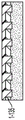
Fig. 1-3B illustrate example elevation views of a nanostructure having multiple material layers arranged in a periodic manner, according to some embodiments. This example illustrates an optical nanostructure having four layers stacked in the z-direction, but any other suitable number of layers may be used. In a multilayer optical nanostructure, layers may be formed at different locations along an axis perpendicular to the surfaces 1-107 of the substrates 1-105 (e.g., along the z-axis). In some cases, the layers may include patterned materials 1-302, 1-304 that are periodic in one dimension (as shown, for example, in fig. 1-3A) or periodic in two dimensions (e.g., along the x-axis and y-axis). The optical nanostructure of fig. 1-3B includes a first plurality of discrete regions (1-302) of a first material (e.g., a dielectric material or a conductive material) and a second plurality of discrete regions (1-304) of a second material (dielectric material, conductive material, or air) having a different refractive index.
In some embodiments, the discrete regions of one layer are staggered relative to the discrete regions of another layer. For example, in the example optical nanostructure of fig. 1-3B, each of the first and third layers is staggered along the x-axis relative to the second and fourth layers.
The height (H1) or thickness of each layer of the multilayer optical nanostructure may be between 50nm and 1 μm in some embodiments, between 50nm and 500nm in some embodiments, between 100nm and 300nm in some embodiments, between 150nm and 300nm in some embodiments, between 100nm and 250nm in some embodiments, between 150nm and 250nm in some embodiments, between 100nm and 150nm in some embodiments, between 150nm and 200nm in some embodiments, between 120nm and 150nm in some embodiments, between 120nm and 140nm in some embodiments, between 120nm and 130nm in some embodiments, or between 130nm and 140nm in some embodiments. Other ranges are also possible. The different layers may have different heights. Alternatively, all layers may have substantially the same height.
In some embodiments, the optical nanostructure may have structural variations that are periodic or quasi-periodic in two dimensions within a plane. Examples of optical nanostructures with structural variations in two dimensions within a plane are depicted in fig. 1-3C and fig. 1-3D. In the example of fig. 1-3C, the columns of second material 1-314 are separated from each other by regions of first material 1-312. The first and second materials 1-312, 1-314 may be any of the materials described above with respect to materials 1-302, 1-304. In the example of fig. 1-3C, the second material 1-314 may have a lower refractive index value than the first material 1-312. In the example of fig. 1-3D, columns of first material 1-322 are separated from each other by regions of second material 1-324. The first and second materials 1-322, 1-324 may be any of the materials described above with respect to materials 1-302, 1-304. In the example of fig. 1-3D, the second material 1-324 may have a higher refractive index value than the first material 1-322.
For the examples depicted in fig. 1-3C and 1-3D, the periodicity along the x-axis (P2 and P3) may have values in any of the ranges described above in connection with fig. 1-3A. Similarly, the periodicity along the y-axis may have values in any of the ranges described above in connection with fig. 1-3A. The features formed from one material within a unit cell of a planar two-dimensional optical nanostructure may have any suitable shape, such as square, rectangular, polygonal, triangular, circular, or irregular. The widths of the structural features along the x-axis (W2 and W3) may have values in any of the ranges described above in connection with fig. 1-3A. Similarly, the width of the structural feature along the y-axis may have a value in any of the ranges described above in connection with fig. 1-3A. In some embodiments, multiple layers of a planar two-dimensional optical nanostructure, such as those shown in fig. 1-3C or fig. 1-3D, can be formed along the z-axis in a stacked fashion. The layers may be interleaved similar to the configuration of fig. 1-3B. The height of each layer (H3) may have a value in any of the ranges described above in connection with fig. 1-3B.
Those periodicities in two or three dimensions provide additional design parameters compared to the optical nanostructure periodicity in one dimension. Thus, the periodicity of the optical nanostructure in two or three dimensions provides greater flexibility to engineer a desired spectral response. For example, in some embodiments, the optical nanostructure in two or three dimensions periodically has a flatter spectral response within the photonic band gap or allowed photonic band and/or has steeper attenuation at the edges of the photonic band gap or allowed photonic band. Steeper attenuation may result in greater differences between the transmission and reflection coefficients of excitation and emission wavelengths near the photonic band gap or edge of the allowed band.
The examples described in connection with fig. 1-3A, 1-3B, 1-3C, and 1-3D exhibit periodicity in one or two dimensions. Additionally or alternatively, quasi-periodic optical nanostructures may be used to achieve spectral responses characterized by forbidden photonic band gaps or allowed photonic bands. According to some embodiments, a quasi-periodic optical nanostructure of the type described therein may comprise two or more alternating building blocks. Examples of quasi-periodic optical nanostructures include one-dimensional photonic structures based on Fibonacci sequences (Fibonacci sequences) (shown in fig. 1-3E), two-dimensional photonic structures based on Penrose structures (shown in fig. 1-3F), three-dimensional photonic structures with icosahedral quasicrystalline structures, one-dimensional, two-dimensional, or three-dimensional photonic structures based on Thue-Morse sequences, one-dimensional, two-dimensional, or three-dimensional photonic structures based on period-doubling sequences, one-dimensional, two-dimensional, or three-dimensional photonic structures based on ludin-Shapiro sequences, one-dimensional, two-dimensional, or three-dimensional photonic structures based on cantotor sequences, and others. Some such structures may produce a spectral response having a photonic band gap or an allowed band, even if they do not have translational symmetry. Quasi-periodic structures of the type described herein may be explicitly aperiodic.
Referring back to fig. 1-1, the presence of the optical nanostructure between the waveguide 1-115 and the sensor 1-122 can cause suppression of the excitation radiation 1-144 while allowing transmission of the emission energy 1-142. The excitation radiation 1-144 may be scattered directly from the waveguides 1-115 and/or by other surfaces of the device. The inventors have recognized and appreciated that the optical nanostructures of the present embodiments may be more effective in reducing the transmission of excitation radiation 1-144 from a wide range of angles than, for example, multilayer dielectric interference filters.
1-4A and 1-4B depict example electric field patterns calculated for an integrated device having an example structure similar to that depicted in FIG. 1-1. However, a microdisk is included in the simulation and is located between the waveguide 1-115 and the optical nanostructure 1-135. The microdisk is further described below and helps to focus the emitted radiation onto the sensors 1-122. For this simulation, the waveguides 1-115 and the optical nanostructure comprised silicon nitride surrounded by silicon oxide. The optical nanostructure is formed as a single-layer, planar, two-dimensional nanostructure having cubic crystals as shown in fig. 1-3D. The first material 1-322 is formed of silicon nitride and the second material 1-324 is formed of silicon oxide. For this example, pitch P3 was 260nm, width W3 was 160nm, and the thickness of layer H3 was 125 nm.
For this example simulation, the excitation radiation has a characteristic wavelength of 532nm (λ ═ λ)Excitation) And the emitted radiation has a characteristic wavelength of 572nm (λ ═ λ)Launching). Other optical nanostructure parameters (periodicity, width, thickness, etc.) and/or other wavelengths (including, for example, excitation wavelengths in the range of 500nm-540nm to produce emission wavelengths in the range of 620nm-650 nm) may be used in other embodiments. The electric field pattern is calculated with software that solves Maxwell's equations (e.g., using finite-difference time-domain analysis) in the simulation domain with initial conditions with the following excitation and emission radiation: 1) changing λ to λExcitationCoupling of radiation from an external source into the single-mode waveguide 1-115, and 2) generating λ ═ λ in the reaction chamber 1-130LaunchingAnd (3) radiation.
E.g. for λ ═ λExcitationAs illustrated in fig. 1-4A, a substantial portion of the electric field is confined to the delivery of excitation radiation into the waveguides 1-115 of the reaction chambers 1-130. However, an appreciable amount of the electric field of the excitation radiation extends below the waveguides 1-115 due to evanescent fields associated with the waveguides and scattering from waveguide walls and other structures within the pixel that includes the reaction chamber. The optical nanostructures 1-135 may reflect a large portion of the excitation electric field back into the waveguide. Without the optical nanostructures 1-135, the electric field can reach the sensors 1-122 and cause background noise. This result would be undesirable because it could reduce the signal-to-noise ratio of the detection system. The use of optical nanostructures between the waveguides 1-115 and the sensors 1-122 results in a substantial reduction in the magnitude of the electric field in the region adjacent to the sensors 1-122. Thus, the amount of excitation energy detected is significantly reduced.
As illustrated in fig. 1-4B, where λ ═ λLaunchingThe emission radiation traveling down from the reaction chamber 1-130 towards the sensor is mostly transmitted through the optical nanostructure 1-135 and may travelTo sensors 1-122. As mentioned above, the microdisk 145 helps to concentrate or condense the emitted radiation onto the sensors 1-122.
The inventors have further recognized that excitation radiation may, in some cases, impinge on the optical nanostructures 1-135 at different angles of incidence. This may be due to, among other possible reasons, multiple reflections of the excitation radiation before impinging on the optical nanostructure and scattering out of the structures within the pixel. Recognizing this problem, the inventors have appreciated that an advantageous feature of optical nanostructures such as the present embodiment is the ability to suppress radiation over a wider range of incidence angles than multilayer interference filters.
Optical nanostructures of the type described herein provide optical suppression over a wide range of incident angles, as compared to other types of optical suppressors. For monolayer optical nanostructures, this behavior is due to the presence of periodic or quasi-periodic structural variations (in one or two dimensions) in the xy plane. Fig. 1-5 are graphs illustrating the rejection ratio associated with two different optical structures at the wavelength of interest, plotted as a function of incident angle (horizontal axis). The suppression ratio is the ratio of the amount of emission radiation transmitted through the optical structure at the characteristic emission wavelength (572 nm in this example) divided by the amount of excitation radiation transmitted through the optical structure at the characteristic excitation wavelength (532 nm in this example). The same amount of power is incident on the optical structure for the emission radiation and the excitation radiation. The angle of incidence is measured relative to a normal to the planar surface of the optical structure.
First rejection ratio curves 1-501 are drawn for multilayer interference filters having 23 layers (although any other number of layers may be used, such as between 10 and 50 layers, between 10 and 40 layers, between 20 and 50 layers, or between 20 and 40 layers, among others) with alternating refractive indices along the z-axis. This optical structure exhibits no structural variation in the xy plane. Therefore, the refractive index is uniform in each xy plane. The rejection ratio of this optical structure is relatively high below 20 °, but drops significantly for incident angles greater than 20 °. This drop means that an appreciable amount of excitation radiation impinging on the optical structure at an angle greater than about 22 ° is transmitted through the optical structure and may generate a background signal at sensors 1-122.
Second inhibition ratio curves 1-502 were drawn for the example monolayer optical nanostructure of the present embodiment having in-plane structural variations. An example optical nanostructure has a cubic lattice in which substantially square silicon nitride pillars are embedded in silicon oxide. The pillars have a width of 140nm and the periodicity in both the x-direction and the y-direction is 250 nm. The thickness of the layer was 125 nm. As illustrated in fig. 1-5, the rejection ratio is greater than about 10 for all angles below 45 °. Thus, the optical nanostructure can provide better suppression of excitation radiation over a wider range of incident angles than a multilayer interference filter.
Another example of an optical structure that may be included at a pixel of an integrated device is shown in fig. 2-1. According to some embodiments, one or more membrane layers 2-110 may be formed over sensors 1-122. The film layers 2-110 may include openings or apertures 2-112 through a light-reducing material. The matting material may comprise a metal, polymer, semiconductor, or any material that suppresses (e.g., absorbs and/or reflects) a substantial portion of the excitation radiation incident on the membrane layers 2-110. In some cases, the luminescent material may also suppress emitted radiation. The apertures 2-112 may allow emissions from the reaction chambers 1-130 to pass through the membrane layers 2-110 and reach the sensors 1-122 while the luminescent material blocks or attenuates radiation from other directions (e.g., from adjacent pixels or from scattered excitation radiation). For example, the membrane layers 2-110 may block or attenuate scattered excitation radiation at wide angles of incidence from impinging on the sensors 1-122 and causing background noise. In some embodiments, the membrane layers 2-110 may be formed of a conductive material and provide a potential reference plane or ground plane to circuitry formed on or over the substrates 1-105. In some embodiments, the membrane layers 2-110 may be formed of a dielectric material. The apertures 2-112 in the membrane layer may be shaped in any suitable manner, such as square, rectangular, circular, oval, polygonal, and the like.
In the example of fig. 2-1, two membrane layers 2-110 are included. A membrane layer is disposed between the waveguide 1-115 and the optical nanostructure 1-135. Another membrane layer is disposed between the optical nanostructure 1-135 and the sensor 1-122. However, it should be understood that any other suitable number of membrane layers and locations may be used. In some cases, a single membrane layer may be used and may be located between reaction chamber 1-130 and optical nanostructure 1-135 or between optical nanostructure 1-135 and sensor 1-122.
In some embodiments, the collection optics assembly 2-160 may be used to collect the emitted radiation emitted from the reaction chamber onto the sensor. In the example of FIG. 2-1, the light collection optics 2-160 are located between the reaction chamber 1-130 and the optical nanostructure 1-135, but other locations are possible. According to some embodiments, the concentrator optical component 2-160 may be made of one or more materials that are transparent at the wavelength of the emitted radiation and have a refractive index that is different from (e.g., greater than) the refractive index of the material surrounding the concentrator optical component 2-160. In this way, the concentrating optical assemblies 2-160 may provide some focusing of the emitted radiation from the reaction chambers 1-130. In some embodiments, the optical components 2-160 may be shaped as a disk (e.g., a microdisk), thereby providing rotational symmetry. The optical assemblies 2-160 may be positioned such that the center of the disk is aligned with the center of the reaction chambers 1-130 along the z-axis. In some embodiments, reaction chambers 1-130, optical assemblies 2-160, diaphragms 2-112, and sensors 1-122 may be aligned with each other along the z-axis.
According to some embodiments, devices of the type described herein may be fabricated by successive steps of material deposition and patterning to create multiple levels in the chip of an integrated device. In some implementations, a chip for an integrated device can be obtained by bonding two substrates or wafers to each other. For example, an integrated device (with example structures at the pixels depicted in fig. 2-1) may be formed from bio-optical substrates 1-100 that may be aligned and bonded to CMOS substrates 1-101. An exemplary bio-optical substrate 1-100 can include a number of pixels, each pixel having a reaction chamber 1-130, a waveguide 1-115, an optical nanostructure 1-135 and optionally one or more membrane layers 2-110 and one or more optical components 2-160. An example CMOS substrate 1-101 may include a number of corresponding pixels with sensors 1-122 (e.g., one sensor per pixel) and circuitry for processing signals generated by the sensors. Layers 2-202 represent conductive or semiconductor layers that may be used to route and/or process signals.
The effect of a pair of membrane layers 2-110 and a light concentrating optical component 2-160 is depicted in fig. 2-2, according to some embodiments. As illustrated, radiation emitted substantially parallel to the z-axis passes directly through the opening in the membrane layer. Radiation emitted at angles substantially off the z-axis is suppressed by one of the membrane layers 2-110. Rays emitted at small angles are focused by the optical assembly 2-160. Thus, radiation emitted from reaction chambers 1-130 is focused onto sensors 1-122, thereby increasing the signal-to-noise ratio.
Another example of a structure that may be included at a pixel of an integrated device is shown in fig. 2-3. According to some embodiments, one or more condensation layers 2-150 may be formed over layers 1-110, and reaction chambers 1-130 may be formed in layers 1-110. The light condensation layer 2-150 may be formed from one or more metal layers. In some cases, the condensation layer 2-150 may include a semiconductor and/or an oxide layer. The light condensing layer 2-150 may reduce or prevent excitation radiation from the light guide 1-115 from traveling into the sample above the reaction chamber 1-130 and exciting fluorophores within the sample. In addition, the light condensing layer 2-150 can prevent external radiation from above the reaction chamber from passing through to the sensor 1-122. Emissions from outside the chamber can cause unwanted background radiation and signal noise. The condensation layers 2-150 may be used in conjunction with any of the embodiments described herein.
An example disposable chip structure 3-100 is shown in fig. 3, according to some embodiments. The disposable chip structure 3-100 may include a bio-optoelectronic chip 3-110 having a semiconductor substrate 3-105 and including a plurality of pixels 3-140 formed on the substrate. Each pixel 3-140 may have the structure and embodiments of the optical nanostructure as described above in connection with fig. 1-2-3. In some embodiments, there may be rows (or columns) of waveguides 3-115 providing excitation radiation to rows (or columns) of pixels 3-140. In some embodiments, waveguides 1-115 of fig. 1-1 can be used as any of these waveguides. The excitation radiation may be coupled into the waveguide, for example, via optical ports 3-150. In some embodiments, a grating coupler may be formed on the surface of the bio-optoelectronic chip 3-110 to couple excitation radiation from the focused beam into one or more receive waveguides connected to the plurality of waveguides 3-115.
The disposable chip structure 3-100 may further include walls 3-120 formed around the pixel regions on the chip 3-110. The walls 3-120 may be part of a plastic or ceramic housing that supports the chip. The walls 3-120 may form at least one reservoir 3-130, wherein at least one sample may be placed and brought into direct contact with the reaction chamber 1-130 on the surface of the biophotonic chip 3-110. For example, the walls 3-120 may prevent the sample in the reservoirs 3-130 from flowing into the region containing the optical ports 3-150 and the grating coupler. In some embodiments, the disposable chip structure 3-100 may further include electrical contacts on the outer surface of the disposable chip and interconnects within the package so that electrical connections can be made between circuitry on the bio-optoelectronic chip 3-110 and circuitry in the instrument in which the chip is mounted.
As mentioned above, the optical nanostructures 1-135 are not limited to the disposable chip structures 3-100 as depicted in FIG. 3. Example embodiments of optical nanostructures 1-135 may be included in other chips, such as imaging chips with photosensor arrays. These imaging chips can be used in cameras, video cameras, smart phones, and optical sensing arrays.
The method for manufacturing optical nanostructures
Fig. 4-1A-4-1J illustrate example structures related to a method for fabricating an optical nanostructure, such as any of the optical nanostructures described above. In the process step depicted in fig. 4-1A, a substrate 4-100 is provided or obtained on which a lithography step may be performed. The substrates 4-100 may include some structures that have been formed on the substrates 4-100. For example, the substrate 4-100 may include a portion of the structure shown in FIG. 1-1 or FIG. 2-1 below the optical nanostructure 1-135. In some embodiments, substrates 4-100 may comprise bulk semiconductor substrates, although other types of bulk substrates may be used in some embodiments.
According to some embodiments, a first material layer 4-102 may be deposited or grown on the substrate 4-100, as depicted in FIG. 4-1B. The first material layer 4-102 may be deposited, for example, by Physical Vapor Deposition (PVD), Plasma Enhanced Chemical Vapor Deposition (PECVD), High Density Plasma (HDP) PECVD or sputtering. The first material layers 4-102 may comprise amorphous silicon, silicon nitride, titanium oxide, and other possible materials described above for the optical nanostructures 1-135, including, for example, silicon-rich nitride materials having particular n (refractive index) and k (extinction coefficient) values, such as silicon-rich nitride I and silicon-rich nitride II. Subsequently, a photoresist layer 4-104 may be deposited on the first material layer 4-102 and patterned using a photolithographic exposure and development process, as depicted in fig. 4-1C. By using the patterned photoresist layer 4-104 as an etch mask, the first material layer 4-102 may be etched in areas where the photoresist has been removed to form voids in the first material layer 4-102, as depicted in fig. 4-1D. The remaining photoresist may be removed from the substrate in a cleaning step. The resulting structure of the etched first material layer 4-102 may comprise a plurality of material regions 4-106, which material regions 4-106 may be configured, for example, according to one of the single layer structures described above in connection with fig. 1-3A-1-3F. For example, material regions 4-106 may form columns of optical nanostructures 1-135.
In some embodiments, a second layer of material 4-108 (having a different index of refraction than the first layer of material) may be deposited over the material regions 4-106, as depicted in FIGS. 4-1E. The second material layer 4-108 may be deposited by any suitable deposition process, such as PVD, PECVD, HDP PECVD or sputtering. The second material layers 4-108 may comprise silicon oxide, silicon nitride, titanium oxide, and other possible materials described above for the optical nanostructures 1-135, including, for example, silicon-rich nitride materials having particular n (refractive index) and k (extinction coefficient) values, such as silicon-rich nitride I and silicon-rich nitride II. In some cases, second material layer 4-108 fills the area between material regions 4-106. According to some embodiments, the second material layer 4-108 may be planarized, for example via Chemical Mechanical Polishing (CMP), resulting in a planar surface as depicted in fig. 4-1F. However, in some cases, one or more layers may be deposited on the second material layers 4-108 without performing a planarization step of the second material layers 4-108. In some embodiments, the structure depicted in FIGS. 4-1F may form an optical nanostructure 1-135, and be configured, for example, according to one of the single-layer structures described above in connection with FIGS. 1-3A-1-3F.
Optionally, one or more additional layers may be added to the optical nanostructure, resulting in an arrangement such as that of fig. 1-3B. Fig. 4-1G-4-1J depict structures associated with steps for forming a second nanostructure layer, according to some embodiments. Similar steps can be used to form additional layers. In some embodiments, a third material layer 4-110 may be deposited or grown on the second material layer 4-108, as depicted in fig. 4-1G. The third material layer 4-110 may be deposited, for example, by PVD, PECVD, HDP PECVD or sputtering. The third material layers 4-110 may comprise amorphous silicon, silicon nitride, titanium oxide, and other possible materials described above for the optical nanostructures 1-135, including, for example, silicon-rich nitride materials having particular n (refractive index) and k (extinction coefficient) values, such as silicon-rich nitride I and silicon-rich nitride II. In some embodiments, the third material layer 4-110 may be the same material as the first material layer 4-102. According to some embodiments, a photoresist layer 4-112 may be deposited on the third material layer 4-110 and patterned using a photolithographic exposure and development process. By using the patterned photoresist layer 4-112 as an etch mask, the third material layer 4-110 may be etched in the areas where the photoresist has been removed, as depicted in fig. 4-1H. The residual photoresist may be removed from the substrate after etching. The resulting structure includes a plurality of material regions 4-114.
Subsequently, a fourth material layer 4-116 may be deposited on the material regions 4-114, for example, by PVD, PECVD, HDP PECVD or sputtering. In some cases, the fourth material layer 4-116 fills the area between material regions 4-114, as depicted in FIG. 4-1I. According to some embodiments, the fourth material layer 4-116 may be made of a material having a refractive index different from the refractive index of the third material layer 4-110. The fourth material layers 4-116 may comprise silicon oxide, silicon nitride, titanium oxide, and other possible materials described above for the optical nanostructures 1-135, including, for example, silicon-rich nitride materials having particular n (refractive index) and k (extinction coefficient) values, such as silicon-rich nitride I and silicon-rich nitride II. In some cases, the fourth material layer 4-116 may be the same material as the second material layer 4-108. According to some embodiments, the fourth material layer 4-116 may be planarized, for example using a CMP process step, resulting in a planar surface as depicted in fig. 4-1J. In other embodiments, one or more layers may be deposited on the fourth material layers 4-116 without planarizing the fourth material layers.
Additional examples of structures associated with another example method for fabricating an optical nanostructure are depicted in fig. 4-2A through 4-2J. This fabrication method is similar in some respects to the fabrication method of fig. 4-1A through 4-1J. However, unlike the fabrication method of FIGS. 4-1A through 4-1J, the dual mask layers 4-104/4-103 and 4-112/4-111 serve as etch masks for forming the material regions. The substrates 4-100 and layers 4-102, 4-104, 4-106, 4-108, 4-110, 4-112, 4-114, and 4-116 may have the same features as those described in connection with fig. 4-1A through 4-1J. In some cases, a dual mask layer (sometimes referred to as a bilayer resist) may provide improved etch selectivity or improved patterning fidelity compared to a single photoresist layer. In some embodiments, one of the mask layers (e.g., 4-103, 4-111) may comprise a so-called "hard mask" formed, for example, of a metal, oxide, nitride, or semiconductor.
An exemplary method of forming an optical nanostructure 1-135 can include obtaining a substrate 4-100 as depicted in fig. 4-2A. As mentioned above in connection with fig. 4-1A, the substrate may include patterned structures. As described above, a first material layer 4-102 may be deposited or grown on the substrate 4-100. Additionally, a first resist layer 4-103 may be deposited on the first material layer 4-102, as depicted in FIG. 4-2B. The first resist layers 4-103 may be a hard material rather than a polymer. For example, the first resist layers 4-103 may comprise silicon oxide, silicon nitride or tantalum, among other possible materials, including, for example, silicon-rich nitride materials having particular n (refractive index) and k (extinction coefficient) values, such as silicon-rich nitride I and silicon-rich nitride II. According to one example, the first material layer 4-102 may be silicon nitride and the first resist layer 4-103 may be silicon oxide, although other material combinations may be used. A photoresist layer 4-104 (second resist layer) may then be deposited over the first resist layer 4-103 and patterned using a photolithographic exposure and development process to produce the structure depicted in fig. 4-2C. Using the patterned photoresist layer 4-104 as a first etch mask, the first resist layer 4-103 may be etched in the areas where the photoresist has been removed to transfer the pattern from the photoresist to the first resist layer 4-103, as depicted in fig. 4-2D. The photoresist layers 4-104 may be removed during and/or after this etching step.
Using the first resist layer 4-103 as an etch mask, the first material layer 4-102 may be etched in the areas where the first resist layer 4-103 has been removed to form voids in the first material layer 4-102. The etching process retains the material regions 4-106 as depicted in fig. 4-2E. In some cases, the remaining first resist layer 4-103 may be removed from the substrate. In other cases, the remaining first resist layer may remain on the material regions 4-106 as illustrated in FIGS. 4-2E. In some cases, the first resist layer may be much thinner than the first material layer 4-102 and the second material layer 4-108 and does not significantly affect the performance of the optical nanostructures 4-135. In some embodiments, the first resist layer 4-103 may be the same material as the second material layer 4-108. After etching to form the material regions 4-106, a second material layer 4-108 may be deposited on the material regions 4-106, as depicted in fig. 4-2F. The second layer of material may fill the area between material regions 4-106. In some cases, the second material layers 4-108 may be planarized, for example via CMP. The structure of fig. 4-2F may form a single layer optical nanostructure 1-135 described above in connection with fig. 1-3A-1-3F.
Optionally, one or more additional layers may be added to the optical nanostructure, resulting in an arrangement such as that of fig. 1-3B. Fig. 4-2G-4-2J depict structures associated with steps for forming a second nanostructure layer, according to some embodiments. Similar steps can be used to form additional layers. For example, a third material layer 4-110 may be deposited or grown on the second material layer 4-108, as depicted in FIGS. 4-2G. Subsequently, a first resist layer 4-111 may be deposited on the third material layer 4-110, and a photoresist layer 4-112 may be deposited on the first resist layer 4-111. The photoresist layer may be patterned using a photolithographic exposure and development process. The photoresist layer 4-112 may provide an etch mask to etch the first resist layer 4-111 in the areas where the photoresist has been removed, and the first resist layer may provide an etch mask to etch the third material layer 4-110, as described above and depicted in fig. 4-2H. The residual photoresist layer 4-112 may be removed during or after etching the third material layer 4-110. The third material layer 4-110 is etched to form material regions 4-114. A fourth material layer 4-116 may be deposited on the material regions 4-114 and may fill the gaps between the material regions 4-114, as depicted in fig. 4-2I. According to some embodiments, the fourth material layer 4-116 may be planarized, as depicted in fig. 4-2J.
The illustrations in fig. 4-1H and 4-2H indicate that second material regions 4-114 are formed over first material regions 4-106 such that the bottoms of second material regions 4-114 are vertically spaced from the tops of first material regions 4-106 with a uniform layer of second material layer 4-108 between such bottoms and tops. However, in some implementations, there may not be a space between such bottoms and tops. For example, the step of planarizing the second material layer may remove most or all of the second material layer 4-108 above the top of the first material regions 4-106 such that the bottom of the second material regions 4-114 are substantially at the same height as the top of the first material regions 4-106.
Example bioanalytical applications
An example bio-analysis application is described in which integrated semiconductors may be used to improve detection of radiation emitted from reaction chambers on disposable chips used in advanced analytical instruments. When installed in the socket of the instrument, the disposable chip may be in optical and electrical communication with the optical and electronic equipment within the advanced analytical instrument. The instrument may include hardware for an external interface so that data from the chip may be communicated to an external network. In embodiments, the term "optical" may refer to ultraviolet, visible, near-infrared, and short wavelength infrared spectral bands. Although various types of analysis can be performed on various samples, the following explanation describes gene sequencing. However, the present invention is not limited to an instrument configured for gene sequencing.
In summary and referring to fig. 5-1A, a portable advanced analysis instrument 5-100 may include one or more pulsed optical sources 5-108 mounted as replaceable modules within instrument 5-100 or otherwise coupled to instrument 5-100. The portable analyzer 5-100 may include an optical coupling system 5-115 and an analysis system 5-160. The optical coupling systems 5-115 may include some combination of optical components (which may, for example, not include any of the following components, including one or more than one of the following components: lenses, mirrors, filters, attenuators, beam steering components, beam shaping components) and are configured to operate on and/or couple the output optical pulses 5-122 from the pulsed optical sources 5-108 to the analysis systems 5-160. The analysis system 5-160 may include a plurality of components arranged to direct optical pulses to at least one reaction chamber for sample analysis, receive one or more optical signals (e.g., fluorescence, backscattered radiation) from the at least one reaction chamber, and generate one or more electrical signals representative of the received optical signals. In some embodiments, the analysis systems 5-160 may include one or more light detectors and may also include signal processing electronics (e.g., one or more microcontrollers, one or more field programmable gate arrays, one or more microprocessors, one or more digital signal processors, logic gates, etc.) configured to process electrical signals from the light detectors. The analysis systems 5-160 may also include data transmission hardware configured to transmit data to and receive data from external devices (e.g., one or more external devices on a network to which the instruments 5-100 may be connected via one or more data communication links). In some embodiments, the analysis system 5-160 may be configured to receive a bio-optoelectronic chip 5-140 holding one or more samples to be analyzed.
Fig. 5-1B depicts another detailed example of a portable analytical instrument 5-100 including a compact pulsed optical source 5-108. In this example, the pulsed optical source 5-108 comprises a compact passively mode-locked laser module 5-110. Passively mode-locked lasers can autonomously generate optical pulses without the application of external pulse signals. In some embodiments, the module may be mounted to the instrument chassis or frame 5-102 and may be located inside the outer housing of the instrument. According to some embodiments, the pulsed optical sources 5-108 may include additional components that may be used to operate the optical sources and operate on the output beams from the optical sources 5-108. The mode-locked lasers 5-110 may include components in or coupled to the laser cavity (e.g., saturable absorbers, acousto-optic modulators, Kerr lenses) that induce phase locking of the laser longitudinal frequency mode. The laser cavity may be defined in part by cavity end mirrors 5-111, 5-119. Such locking of the frequency mode causes pulsed operation of the laser (e.g., intracavity pulses 5-120 bounce back and forth between the cavity end mirrors) and produces a train of partially transmitted output optical pulses 5-122 from one end mirror 5-111.
In some cases, the analytical instrument 5-100 is configured to receive a removable packaged bio-optoelectronic or optoelectronic chip 5-140 (also referred to as a "disposable chip"). The disposable chip may comprise a bio-optoelectronic chip 3-110, as depicted in fig. 4, for example comprising a plurality of reaction chambers, an integrated optical component arranged to deliver optical excitation energy to the reaction chambers, and an integrated light detector arranged to detect fluorescence emissions from the reaction chambers. In some embodiments, the chip 5-140 may be discarded after a single use, while in other embodiments, the chip 5-140 may be reused two or more times. When received by the instrument 5-100, the chip 5-140 may be in electrical and optical communication with the pulsed optical source 5-108 and with equipment in the analysis system 5-160. For example, electrical communication may be via electrical contacts on the chip package.
In some embodiments and referring to fig. 5-1B, the disposable chip 5-140 may be mounted (e.g., connected via a socket) on an electronic circuit board 5-130, such as a Printed Circuit Board (PCB) that may include additional instrument electronics. For example, the PCB 5-130 may include circuitry configured to provide electrical power, one or more frequency signals, and control signals to the optoelectronic chip 5-140, and signal processing circuitry arranged to receive signals representative of fluorescent emissions detected from the reaction chamber. In some embodiments, the data returned from the optoelectronic chip may be partially or fully processed by electronics on the instrument 5-100, although the data may be transmitted to one or more remote data processors via a network connection. The PCB 5-130 may also include circuitry configured to receive feedback signals from the chip related to the optical coupling and power level of the optical pulses 5-122 coupled into the waveguide of the optoelectronic chip 5-140. Feedback signals may be provided to one or both of the pulsed optical sources 5-108 and the optical systems 5-115 to control one or more parameters of the output beams of the optical pulses 5-122. In some cases, the PCBs 5-130 may provide or route power to the pulsed optical sources 5-108 for operating the optical sources and associated circuitry in the optical sources 5-108.
According to some embodiments, the pulsed optical source 5-108 comprises a compact mode-locked laser module 5-110. The mode locked laser may include a gain medium 5-105 (which may be a solid state material in some embodiments), an output coupler 5-111, and a laser cavity end mirror 5-119. The optical cavity of the mode-locked laser may be constrained by output coupler 5-111 and end mirror 5-119. The optical axis 5-125 of the laser cavity may have one or more folds (turns) to increase the length of the laser cavity and provide a desired pulse repetition rate. The pulse repetition rate is determined by the length of the laser cavity (e.g., the time for the optical pulse to round trip within the laser cavity).
In some embodiments, additional optical components for beam shaping, wavelength selection, and/or pulse formation may be present in the laser cavity (not shown in fig. 5-1B). In some cases, end mirrors 5-119 include saturable-absorber mirrors (SAMs) that induce passive mode locking of longitudinal cavity modes and cause pulsed operation of mode-locked lasers. The mode-locked laser module 5-110 may further include a pump source (e.g., a laser diode, not shown in fig. 5-1B) for exciting the gain medium 5-105. Additional details of Mode-Locked Laser modules 5-110 can be found in U.S. patent application No. 15/844,469 entitled "Compact Mode-Locked Laser Module," filed on 2017, 12, 15, which is incorporated herein by reference.
When the laser 5-110 is mode-locked, the intra-cavity pulse 5-120 may be cycled between the end mirror 5-119 and the output coupler 5-111, and a portion of the intra-cavity pulse may be transmitted as an output pulse 5-122 via the output coupler 5-111. Thus, when the intra-cavity pulse 5-120 bounces between the output coupler 5-111 and the end mirror 5-119 in the laser cavity, a series of output pulses 5-122 as depicted in the graph of fig. 5-2 can be detected at the output coupler.
FIG. 5-2 depicts temporal intensity of output pulses 5-122The curves, but the icons are not drawn to scale. In some embodiments, the peak intensity values of the transmitted pulses may be approximately equal, and the curve may have a gaussian time curve, such as, but not limited to, sech2Other curves of the curve may be possible. In some cases, the pulses may not have a symmetric time profile and may have other temporal shapes. The duration of each pulse may be characterized by a full-width-half-maximum (FWHM) value, as indicated in FIG. 5-2. According to some embodiments of mode-locked lasers, the ultrashort optical pulses may have a FWHM value of less than 100 picoseconds (ps). In some cases, the FWHM value may be between about 5ps and about 30 ps.
The output pulses 5-122 may be separated by regular intervals T. For example, T may be determined by the round-trip travel time between the output coupler 5-111 and the cavity end mirror 5-119. According to some embodiments, the pulse separation interval T may be between about 1ns and about 30 ns. In some cases, the pulse separation interval T may be between about 5ns and about 20ns, corresponding to a laser cavity length (approximate length of the optical axis 5-125 within the laser cavity) of between about 0.7 meters and about 3 meters. In an embodiment, the pulse separation interval corresponds to a round trip travel time in the laser cavity, such that a cavity length of 3 meters (6 meters round trip distance) provides a pulse separation interval T of about 20 ns.
According to some embodiments, the desired pulse separation interval T and laser cavity length may be determined by a combination of the number of reaction chambers on the chip 5-140, the fluorescence emission characteristics, and the speed of the data processing circuitry used to read data from the optoelectronic chip 5-140. In embodiments, different fluorophores can be distinguished by their different fluorescence decay rates or characteristic lifetimes. Thus, there needs to be sufficient pulse separation interval T to collect appropriate statistics of the selected fluorophores to distinguish between their different decay rates. In addition, if the pulse separation interval T is too short, the data processing circuitry cannot keep up with the large amount of data being collected by the large number of chambers. A pulse separation interval T of between about 5ns and about 20ns is suitable for fluorophores having a decay rate of at most about 2ns and for processing data from between about 60,000 and 10,000,000 reaction chambers.
According to some implementations, the beam steering modules 5-150 may receive output pulses from the pulsed optical sources 5-108 and be configured to adjust at least a position and an angle of incidence of the optical pulses on an optical coupler (e.g., a grating coupler) of the optoelectronic chips 5-140. In some cases, the output pulses 5-122 from the pulsed optical sources 5-108 may be operated by the beam steering modules 5-150 to additionally or alternatively change the beam shape and/or beam rotation at the optical couplers on the optoelectronic chips 5-140. In some implementations, the beam steering modules 5-150 can further provide focusing and/or polarization adjustment of the output pulsed light beam onto the optical coupler. One example of a beam steering module is described in U.S. patent application No. 15/161,088 entitled "Pulsed Laser and biological System," filed on 5/20/2016, which is incorporated herein by reference. Another example of a Beam Steering module is described in independent U.S. patent application No. 62/435,679, entitled Compact Beam Shaping and Steering Assembly, filed on Ser. No. 12/16 2016, which is incorporated herein by reference.
For example, referring to FIGS. 5-3, output pulses 5-122 from a pulsed optical source may be coupled into one or more optical waveguides 5-312 on the bio-optoelectronic chip 5-140. In some embodiments, the optical pulses may be coupled to one or more waveguides via grating couplers 5-310, although coupling to the ends of one or more optical waveguides on an optoelectronic chip may be used in some embodiments. According to some embodiments, the quad detector 5-320 may be located on a semiconductor substrate 5-305 (e.g., a silicon substrate) for assisting in aligning the beam of the optical pulse 5-122 to the grating coupler 5-310. The one or more waveguides 5-312 and the one or more reaction chambers 5-330 may be integrated on the same semiconductor substrate together with an intermediate dielectric layer (e.g. a silicon dioxide layer) between the substrate, the waveguides, the reaction chambers and the photodetectors 5-322.
Each waveguide 5-312 may include a tapered portion 5-315 below the reaction chamber 5-330 to equalize the optical power coupled into the reaction chamber along the waveguide. Reducing the wedge can force more light energy outside the core of the waveguide, thereby increasing coupling with the reaction chamber and compensating for optical losses along the waveguide, including light losses coupled into the reaction chamber. A second grating coupler 5-317 may be located at the end of each waveguide to direct the light energy to the integrated photodiode 5-324. For example, the integrated photodiode may detect an amount of power coupled down the waveguide and provide the detected signal to feedback circuitry that controls the beam steering modules 5-150.
Reaction chamber 5-330 or reaction chamber 5-330 may be aligned with the tapered portion 5-315 of the waveguide and recessed in slot 5-340. There may be a light detector 5-322 located on the semiconductor substrate 5-305 for each reaction chamber 5-330. In some embodiments, a semiconductor absorber (shown in fig. 5-5 as optical filter 5-530) may be located between the waveguide at each pixel and the optical detector 5-322. Metal coatings and/or multilayer coatings 5-350 can be formed around the reaction chamber and over the waveguide to prevent optical excitation of fluorophores that are not in the reaction chamber (e.g., dispersed in a solution over the reaction chamber). The metallic coating and/or multilayer coating 5-350 may be raised above the edges of the slots 5-340 to reduce absorptive losses of the optical energy in the waveguides 5-312 at the input and output ends of each waveguide.
There may be multiple rows of waveguides, reaction chambers, and time-binning photodetectors on the optoelectronic chips 5-140. For example, in some embodiments, there may be 128 rows of 512 reaction chambers each for a total of 65,536 reaction chambers. Other embodiments may include fewer or more reaction chambers, and may include other layout configurations. The optical power from the pulsed optical source 5-108 may be distributed to the plurality of waveguides via one or more star couplers or multi-mode interference couplers, or by any other means located between the optical coupler 5-310 and the plurality of waveguides 5-312 of the chip 5-140.
FIG. 5-4 illustrates the coupling of optical energy from the optical pulse 5-122 in the wedge-shaped portion 5-315 of the waveguide to the reaction chamber 5-330. The pattern has been generated by electromagnetic field simulations of optical waves, taking into account the waveguide dimensions, the chamber dimensions, the optical properties of the different materials and the distance of the tapered portion of the waveguide 5-315 from the reaction chamber 5-330. For example, the waveguide may be formed of silicon nitride in the surrounding dielectric 5-410 of silicon dioxide. The waveguides, surrounding medium and reaction chambers can be formed by microfabrication processes described in U.S. patent application No. 14/821,688 entitled "Integrated Device for binding, Detecting and Analyzing Molecules" filed on 8/7/2015. According to some embodiments, the evanescent optical field 5-420 couples optical energy transmitted by the waveguide to the reaction chamber 5-330.
Non-limiting examples of biological reactions occurring in reaction chambers 5-330 are depicted in FIGS. 5-5. The examples depict sequential incorporation of nucleotides or nucleotide analogs into a growing strand complementary to a target nucleic acid. Sequential incorporation can occur in the reaction chamber 5-330, and can be detected by advanced analytical instruments to sequence the DNA. The reaction chamber may have a depth of between about 150nm and about 250nm and a diameter of between about 80nm and about 160 nm. Metallization layers 5-540 (e.g., metallization for electrical reference potentials) may be patterned over the photodetectors 5-322 to provide an aperture or diaphragm that suppresses stray radiation from adjacent reaction chambers and other unwanted light sources. According to some embodiments, the polymerase 5-520 may be located within the reaction chamber 5-330 (e.g., attached to a substrate of the chamber). The polymerase may dissolve the target nucleic acid 5-510 (e.g., a portion of the nucleic acid derived from DNA) and sequence the growing strand of complementary nucleic acid to produce a DNA growing strand 5-512. Nucleotides or nucleotide analogs labeled with different fluorophores can be dispersed in the solution above and within the reaction chamber.
As depicted in FIGS. 5-6, when the labeled nucleotide or nucleotide analog 5-610 is incorporated into a complementary nucleic acid growth strand, one or more of the linked fluorophores 5-630 can be repeatedly excited by pulses of light energy coupled from the waveguide 5-315 into the reaction chamber 5-330. In some embodiments, one or more fluorophores 5-630 can be linked to one or more nucleotides or nucleotide analogs 5-610 using any suitable linker 5-620. The incorporation event may last for a period of up to about 100 ms. During this time, a fluorescence emission pulse generated by excitation of the fluorophore by a pulse from the mode-locked laser may be detected, for example, with a time-binning photodetector 5-322. In some embodiments, there may be one or more additional integrated electronics 5-323 at each pixel for signal processing (e.g., amplification, readout, routing, signal pre-processing, etc.). According to some embodiments, each pixel may include at least one optical filter 5-530 (e.g., a semiconductor absorber) that passes fluorescent emissions and reduces radiation transmission from the excitation pulse. Some embodiments may not use optical filters 5-530. By linking fluorophores with different emission characteristics (e.g., fluorescence decay rate, intensity, fluorescence wavelength) to different nucleotides (A, C, G, T), the different emission characteristics are detected and distinguished when the DNA strands 5-512 are nucleic acids and the genetic sequence of the DNA growing strands can be determined.
According to some embodiments, an advanced analysis instrument 5-100 configured to analyze a sample based on fluorescence emission characteristics may detect differences in fluorescence lifetime and/or intensity between different fluorescent molecules, and/or differences between lifetime and/or intensity of the same fluorescent molecule in different environments. By way of explanation, FIGS. 5-7 plot two different fluorescence emission probability curves (A and B), which may represent, for example, fluorescence emissions from two different fluorescent molecules. With reference to curve A (dashed line), the probability p of fluorescence emission from the first molecule after excitation by a short or ultrashort optical pulseA(t) may decay over time as depicted. In some cases, the decrease in probability of a photon being emitted over time may be due to an exponential decay function Is represented by the formula, wherein PAoIs the initial emission probability and1is a time parameter associated with the first fluorescent molecule that characterizes the emission decay probability. Tau is1May be referred to as the "fluorescence lifetime", "emission lifetime" or "lifetime" of the first fluorescent molecule. In some cases, τ can be altered by the local environment of the fluorescent molecule1The value is obtained. Other fluorescent molecules may have emission characteristics different from those shown in curve a. For example, another fluorescent molecule may have a different decay curve than a single exponential decay, and its lifetime may be characterized by a half-life value or some other measure.
The second fluorescent molecule may have an exponential decay curve pB(t), but with measurably different lifetimes τ 2, as depicted by curve B in FIGS. 5-7. In the illustrated example, the lifetime of the second fluorescent molecule of curve B is longer than the lifetime of curve AShort lifetime and earlier emission probability p after excitation of the second moleculeBThe higher the emission probability of (t) than curve a. In some embodiments, the different fluorescent molecules may have a lifetime or half-life value ranging from about 0.1ns to about 20 ns.
Differences in fluorescence emission lifetimes may be used to distinguish between the presence or absence of different fluorescent molecules and/or to distinguish between different environments or conditions to which fluorescent molecules are subjected. In some cases, distinguishing fluorescent molecules based on lifetime (rather than, for example, emission wavelength) may simplify aspects of the analytical instrument 5-100. As an example, when discriminating fluorescent molecules based on lifetime, wavelength discrimination optics (such as wavelength filters, dedicated detectors for each wavelength, dedicated pulsed optical sources and/or diffractive optics at different wavelengths) may be reduced in number or eliminated. In some cases, a single pulsed optical source operating at a single characteristic wavelength may be used to excite different fluorescent molecules that emit within the same wavelength range of the spectrum but have measurably different lifetimes. An analysis system that uses a single pulsed optical source rather than multiple sources operating at different wavelengths to excite and discriminate between different fluorescent molecules emitting in the same wavelength range may be less complex to operate and maintain, more compact, and may be manufactured at lower cost.
While analysis systems based on fluorescence lifetime analysis may have certain benefits, the amount of information obtained by the analysis system and/or the accuracy of detection may be increased by allowing additional detection techniques. For example, some biological analysis systems 5-160 may additionally be configured to identify one or more characteristics of the sample based on the fluorescence wavelength and/or fluorescence intensity.
Referring again to fig. 5-7, according to some embodiments, the different fluorescence lifetimes may be distinguished with a photodetector configured to time-bin the fluorescence emission events after excitation of the fluorescent molecules. Time binning may occur during a single charge accumulation cycle of the photodetector. The charge accumulation cycle is the interval between readout events during which photo-generated carriers (photogenerated carriers) are accumulated in the bins of a time-binning photodetector. Is launched by a pairThe concept of time binning of the pieces to determine fluorescence lifetime is graphically incorporated in fig. 5-8. When time t iseOnly at t1The fluorescent molecules or a subset of fluorescent molecules of the same type (e.g., the type corresponding to curve B of fig. 5-7) are excited by a short or ultrashort optical pulse. For larger subsets, the emission intensity may have a time curve similar to curve B, as depicted in fig. 5-8.
However, for a single molecule or a few molecules, for this example, the emission of fluorescence photons occurs according to the statistical data of curve B in fig. 5-7. The time-binning photodetectors 5-322 may accumulate carriers generated by emission events into discrete time bins. Three bins are indicated in fig. 5-8, but fewer or more bins may be used in embodiments. Excitation time t relative to fluorescent moleculeseThe bins are resolved temporally. For example, the first bin may accumulate at time t1And t2Carriers generated during the interval in between, which occurs after the excitation event at time te. The second bin may accumulate at time t2And t3Carriers generated during the interval therebetween, and the third cell may accumulate at time t3And t4Carriers generated during the interval therebetween. When a large number of emission events are summed, carriers accumulated in the time bins may approach the decay intensity curves shown in fig. 5-8, and the binned signals may be used to distinguish between different fluorescent molecules or different environments in which the fluorescent molecules are located.
Examples of time Binning photodetectors 5-322 are described in U.S. patent application No. 14/821,656 entitled "Integrated Device for Temporal Binning of Received Photons" filed on 8/7/2015 and in U.S. patent application No. 15/852,571 entitled "Integrated photon with Direct Pixel" filed on 12/22/2017, which are all incorporated herein by reference in their entirety. For purposes of explanation, non-limiting embodiments of time-binning light detectors are depicted in fig. 5-9. The single time-binning light detector 5-322 may comprise a photon absorption/carrier generation region 5-902, a carrier discharge channel 5-906 and a plurality of carrier storage bins 5-908a, 5-908b all formed on a semiconductor substrate. The carrier transport channels 5-907 may be connected between the photon absorption/carrier generation regions 5-902 and the carrier storage divisions 5-908a, 5-908 b. In the illustrated example, two carrier storage bins are shown, but there may be more or fewer. There may be readout channels 5-910 connected to the carrier storage cells. Photon absorption/carrier generation regions 5-902, carrier discharge channels 5-906, carrier storage bins 5-908a, 5-908b, and readout channels 5-910 may be formed by locally doping the semiconductor and/or forming adjacent insulating regions to provide photodetection capability, confinement, and transport of carriers. The time-binning optical detector 5-322 may also comprise a plurality of electrodes 5-920, 5-921, 5-922, 5-923, 5-924 formed on the substrate, the electrodes being configured to generate an electric field in the device for transporting carriers through the device.
In operation, a portion of the excitation pulse 5-122 from the pulsed optical source 5-108 (e.g., a mode-locked laser) is delivered to the reaction chamber 5-330 above the time-binning optical detector 5-322. Initially, some excitation radiation photons 5-901 may reach the photon absorption/carrier generation region 5-902 and generate carriers (shown as light shaded circles). There may also be some fluorescence emitting photons 5-903 which arrive with the excitation radiation photons 5-901 and generate corresponding carriers (shown as dark shaded circles). Initially, the number of carriers generated by the excitation radiation may be too large compared to the number of carriers generated by fluorescence emission. Time interval te-t1The initial carriers generated during l can be suppressed by gating them into the carrier discharge channels 5-906, for example, with the first electrodes 5-920.
Later, most of the fluorescence emitting photons 5-903 reach the photon absorption/carrier generation region 5-902 and generate carriers (indicating dark shaded circles) that provide a useful and detectable signal representative of the fluorescence emission from the reaction chamber 5-330. According to some detection methods, the second electrode 5-921 and the third electrode 5-923 may be gated later on to be later on (e.g., at a second time interval | t |)1-t2During | period) generated carriers are guided to the first carrier storage lattices 5 to 908 a. Then, later (e.g., at a third time interval | t)2-t3During) the fourth electrodes 5-922 and the fifth electrodes 5-924 may be gated to direct carriers to the second carrier storage cells 5-908 b. For a large number of fire pulses, charge accumulation may continue after a fire pulse in such a way as to accumulate a significant number of carriers and signal levels in each carrier storage cell 5-908a, 5-908 b. Later, the signal may be read out from the bins. In some embodiments, the time intervals corresponding to each storage bin are in units of sub-nanosecond time scales, although in some embodiments (e.g., in embodiments where the fluorophore has a longer decay time) a longer time scale may be used.
The process of generating and time-binning carriers after an excitation event (e.g., an excitation pulse from a pulsed optical source) may occur once after a single excitation pulse or repeated multiple times after multiple excitation pulses during a single charge accumulation cycle of time-binning photodetectors 5-322. After charge accumulation is complete, carriers may be read out of the storage bins via readout channels 5-910. For example, a sequence of appropriate biases may be applied to electrodes 5-923, 5-924 and at least to electrodes 5-940 to remove carriers from storage cells 5-908a, 5-908 b. The charge accumulation and readout process can occur in massively parallel operations on the photo chips 5-140, creating a data frame.
Although the examples described in connection with fig. 5-9 include multiple charge storage bins 5-908a, 5-908b, in some cases a single charge storage bin may actually be used. For example, only bin 1 may be present in time-bin light detectors 5-322. In this case, a single storage bin 5-908a may be operated in a variable time-gated manner to look at different time intervals after different firing events. For example, after a pulse in the first series of excitation pulses, the electrodes for storage bins 5-908a may be gated to collect data during a first time interval (e.g., at a second time interval | t 1-t)2During | and) the generated carriers, and the accumulated signal may be read out after a first predetermined number of pulses. Following a pulse in a subsequent series of excitation pulses in the same chamber, the same electrode used to store bins 5-908a may be gated to collect inDuring different intervals (e.g. at a third time interval | t)2-t3During | and) the generated carriers, and the accumulated signal may be read out after a second predetermined number of pulses. If desired, carriers can be collected in a similar manner during subsequent time intervals. In this way, a single carrier storage bin may be used to generate signal levels corresponding to fluorescent emission during different time periods after the excitation pulse reaches the reaction chamber.
Regardless of the manner in which charge accumulation is performed for different time intervals after excitation, the readout signal may provide a histogram representing, for example, bins of fluorescence emission decay characteristics. An example process is illustrated in fig. 5-10A and 5-10B, where two charge storage bins are used to acquire fluorescent emission from the reaction chamber. The bins of the histogram may indicate the number of photons detected during each time interval after excitation of the fluorophores in the reaction chamber 5-330. In some embodiments, the signals for binning will be accumulated after a large number of fire pulses, as depicted in fig. 5-10A. The excitation pulses may be separated by a pulse interval time T at a time Te1、te2、te3、…、teNThis occurs. In some cases, there may be between 105 and 107 excitation pulses 5-122 (or portions thereof) applied to the reaction chamber during signal accumulation in the electron reservoir bin for a single event observed in the reaction chamber (e.g., a single nucleotide incorporation event in a DNA analysis). In some embodiments, one bin (bin 0) may be configured to detect the amplitude of the excitation energy delivered with each optical pulse, and may be used as a reference signal (e.g., to normalize the data). In other cases, the excitation pulse amplitude may be stable, determined one or more times during signal acquisition, and not determined after each excitation pulse, such that there is no bin 0 signal acquisition after each excitation pulse. In such cases, carriers generated by the excitation pulse may be suppressed and dumped as photon absorption/carrier generation region 5-902 described above in connection with fig. 5-9.
In some embodiments, only a single photon may be emitted from the fluorophore after the excitation event, as depicted in fig. 5-10A. At the time ofTime te1After the first firing event of (c), time tf1May be within a first time interval (e.g., at time t)1And t2In between) occurs such that the resulting electronic signal accumulates in the first electron storage cell (contributing to cell 1). At time te2In the following firing event, time tf2May be within a second time interval (e.g., at time t)2And t3In between) occurs such that the resulting electrical signal contributes to cell 2. At time te3May occur within a first time interval at a time tf3And (4) transmitting.
In some embodiments, the fluorescent photons emitted and/or detected after each excitation pulse received at reaction chambers 5-330 may be absent. In some cases, there may be as few as one fluorescence photon detected at the reaction chamber for every 10,000 excitation pulses delivered to the reaction chamber. One advantage of implementing the mode-locked laser 5-110 as a pulsed excitation source 5-108 is that the mode-locked laser can produce short optical pulses with high intensity and fast off-time at high pulse repetition rates (e.g., between 50MHz and 250 MHz). With such high pulse repetition rates, the number of excitation pulses within a 10 millisecond charge accumulation interval can be 50,000 to 250,000, such that detectable signals can be accumulated.
After a number of excitation events and carrier accumulation, the carrier storage bins of the time-binning optical detectors 5-322 may be read out to provide a multi-valued signal (e.g., a histogram of two or more values, an N-dimensional vector, etc.) to the reaction chamber. The signal value of each bin may depend on the rate of decay of the fluorophore. For example, and referring again to fig. 5-8, the signal for the fluorophore with decay curve B in bins 1-2 will be higher than for the fluorophore with decay curve a. The values from the bins can be analyzed and compared to calibration values and/or to each other to determine the particular fluorophore present. For sequencing applications, identifying a fluorophore can identify a nucleotide or nucleotide analog incorporated into, for example, a growing strand of DNA. For other applications, identifying a fluorophore may determine the identity of a molecule or sample of interest that may be attached to the fluorophore.
To further aid in understanding the signal analysis, the accumulated multi-bin values may be plotted as a histogram, for example as depicted in fig. 5-10B, or may be recorded as a vector or position in an N-dimensional space. A calibration round can be performed separately to acquire calibration values (e.g., calibration histograms) of multivalued signals of four different fluorophores connected to four nucleotides or nucleotide analogs. As an example, the calibration histogram can be presented as depicted in FIGS. 5-11A (fluorescent label associated with T nucleotide), 5-11B (fluorescent label associated with A nucleotide), 5-11C (fluorescent label associated with C nucleotide), and 5-11D (fluorescent label associated with G nucleotide). Comparison of the measured multivalued signal (corresponding to the histograms of FIGS. 5-10B) with the calibration multivalued signal can determine the identity "T" of the nucleotide or nucleotide analog incorporated into the growing strand of DNA (FIGS. 5-11A).
In some embodiments, fluorescence intensity may additionally or alternatively be used to distinguish between different fluorophores. For example, some fluorophores may emit at significantly different intensities, or even though their decay rates may be similar, their excitation probabilities may have significant differences (e.g., differences of at least about 35%). By referencing the binned signal (bin 5-3) with the measured excitation energy and/or other acquired signals, different fluorophores can be distinguished based on intensity level.
In some embodiments, a different number of fluorophores of the same type can be attached to different nucleotides or nucleotide analogs, such that the nucleotides can be identified based on fluorophore intensity. For example, two fluorophores can be attached to a first nucleotide (e.g., "C") or nucleotide analog, and four or more fluorophores can be attached to a second nucleotide (e.g., "T") or nucleotide analog. Due to the different number of fluorophores, there may be different excitation and fluorophore emission probabilities associated with different nucleotides. For example, there may be more emission events of "T" nucleotides or nucleotide analogs during the signal accumulation interval, such that the apparent intensity of the bins is significantly higher than for "C" nucleotides or nucleotide analogs.
Distinguishing between nucleotides or any other biological or chemical sample based on the fluorophore decay rate and/or fluorophore intensity enables simplification of the optical excitation and detection system in the analysis instrument 5-100. For example, optical excitation may be performed with a single wavelength source (e.g., a source that produces one characteristic wavelength rather than multiple sources or a source operating at multiple different characteristic wavelengths). In addition, wavelength discrimination optics and filters may not be required in the detection system to distinguish between fluorophores of different wavelengths. In addition, a single photodetector may be used for each reaction chamber to detect emissions from different fluorophores.
The phrase "characteristic wavelength" or "wavelength" is used to refer to a center or dominant wavelength within a limited bandwidth of radiation (e.g., a center or peak wavelength within a 20nm bandwidth output by a pulsed optical source). In some cases, "characteristic wavelength" or "wavelength" may be used to refer to a peak wavelength within the total radiation bandwidth output by the source.
Fluorophores with emission wavelengths in the range between about 560nm and about 900nm may provide a sufficient amount of fluorescence for detection by time-binning photodetectors (which may be fabricated using CMOS processes on silicon wafers). Such fluorophores can be attached to biomolecules of interest, such as nucleotides or nucleotide analogs for gene sequencing applications. Fluorescence emission in this wavelength range can be detected with higher responsivity than fluorescence at longer wavelengths in silicon-based photodetectors. In addition, fluorophores and associated connectors in this wavelength range may not interfere with incorporation of nucleotides or nucleotide analogs into the DNA growth strand. In some embodiments, fluorophores that emit at wavelengths in the range between about 560nm and about 660nm may be optically excited by a single wavelength source. An exemplary fluorophore in this range is Alexa Fluor 647, which is available from Thermo Fisher Scientific Inc. of Waltham, Massachusetts. Excitation energy at shorter wavelengths (e.g., between about 500nm and about 650 nm) may be used to excite fluorophores that emit at wavelengths between about 560nm and about 900 nm. In some embodiments, a time-binning photodetector may be effective to detect longer wavelength emissions from the reaction chamber, for example, by incorporating other materials (such as Ge) into the photodetector active region.
Conclusion IV
Having thus described several aspects of several embodiments of system architectures for advanced analysis systems 5-100, it should be apparent that various alterations, modifications, and improvements will readily occur to those skilled in the art. Such alterations, modifications, and improvements are intended to be part of this disclosure, and are intended to be within the spirit and scope of the invention. While the present teachings have been described in connection with various embodiments and examples, it is not intended that the present teachings be limited to such embodiments or examples. On the contrary, the present teachings encompass various alternatives, modifications, and equivalents, as will be appreciated by those of skill in the art.
While various inventive embodiments have been described and illustrated, those of ordinary skill in the art will readily envision a variety of other means and/or structures for performing the function and/or obtaining the results and/or one or more of the advantages described, and each of such variables and/or modifications is deemed to be within the scope of the described inventive embodiments. More generally, those skilled in the art will readily appreciate that all parameters, dimensions, materials, and configurations described are meant to be exemplary and that the actual parameters, dimensions, materials, and/or configurations will depend upon the specific application or applications for which the inventive teachings is/are used. Those skilled in the art will recognize, or be able to ascertain using no more than routine experimentation, many equivalents to the specific inventive embodiments described. It is, therefore, to be understood that the foregoing embodiments are presented by way of example only and that, within the scope of the appended claims and equivalents thereto, inventive embodiments may be practiced otherwise than as specifically described and claimed. Inventive embodiments of the present invention may be directed to individual features, systems, system upgrades, and/or methods described. In addition, any combination of two or more such features, systems and/or methods, if such features, systems, system upgrades and/or methods are not mutually inconsistent, is included within the inventive scope of the present invention.
Moreover, while some advantages of the invention may be indicated, it is to be understood that not every embodiment of the invention will include every described advantage. Some embodiments may not implement any features described as advantageous. Accordingly, the foregoing description and drawings are by way of example only.
All documents and similar materials cited in this application, including but not limited to patents, patent applications, articles, books, treatises, and web pages, are expressly incorporated by reference in their entirety, regardless of the format in which they are presented. In the event that one or more of the incorporated documents and similar materials differ or contradict this application, including but not limited to the defined terms, usage of terms, described techniques, or the like, this application controls.
The section headings used are for organizational purposes only and are not to be construed as limiting the object described in any way.
Further, the described techniques may be implemented as a method, which has provided at least one example. The actions performed as part of the method may be ordered in any suitable way. Thus, the following embodiments can be constructed: where acts are performed in an order different than illustrated, which may include performing some acts concurrently, even though such acts are shown as sequential acts in the illustrative embodiments.
All definitions, as defined and used, should be understood to be within the ordinary meaning of the dictionary definition, the definition in the incorporated by reference document, and/or the defined term.
Numerical values and ranges may be described as approximate or exact values or ranges in the specification and claims. For example, in some cases, the terms "about," "approximately," and "substantially" may be used with respect to a value. Such references are intended to encompass reference values and reasonable deviations in adding and subtracting such values. For example, the phrase "between about 10 and about 20" is intended to mean "between exactly 10 and exactly 20" in some embodiments, and "between 10 ± δ 1 and 20 ± δ 2" in some embodiments. The amount of the variable δ 1, δ 2 of the value may be less than 5% of the value in some embodiments, less than 10% of the value in some embodiments, and again less than 20% of the value in some embodiments. In embodiments where a larger range of values is given (e.g., a range comprising two or more orders of magnitude), the amount of the variables δ 1, δ 2 of the values may be as high as 50%. For example, if the operable range extends from 2 to 200, "about 80" may cover a value between 40 and 120, and the range may be as large as between 1 and 300. Where an accurate value is required, the term "accurate" is used, e.g., "between accurate 2 and accurate 200".
The term "adjacent" may refer to two components being configured in close proximity to one another (e.g., within a distance of less than about one-fifth of the lateral or vertical dimension of the larger of the two components). In some cases, there may be intermediate structures or layers between adjacent components. In some cases, adjacent components may be immediately adjacent to one another without intervening structures or components.
The indefinite article "a" or "an" as used in this specification and in the claims should be understood to mean "at least one" unless clearly indicated to the contrary.
As used in this specification and the claims, the phrase "and/or" should be understood to mean "either or both" of the elements so combined, i.e., elements that are present in combination in some cases and not present in combination in other cases. The use of "and/or" listed components should be construed in the same way, that is, "one or more" of the components so combined. There may optionally be additional components other than the components specifically identified by the "and/or" clause, whether related or unrelated to those components specifically identified. Thus, as a non-limiting example, reference to "a and/or B" when used in conjunction with open language such as "comprising" may refer in one embodiment to only a (optionally including components other than B); in another embodiment, to B only (optionally including components other than a); in yet another embodiment to both a and B (including other components as appropriate); and the like.
As used in this specification and the claims, "or" should be understood to have the same meaning as "and/or" as defined above. For example, when items in a list are separated, "or" and/or "should be interpreted as being inclusive, i.e., including at least one (but also including more than one) of the plurality or series of elements, and optionally additional unlisted items. To the contrary, terms such as "only one of" or "exactly one of" or (as used in the claims) "consisting of …" are intended to mean to include exactly one of a plurality or series of components. In general, when preceding an exclusive term, such as "any," "one of," "only one of," or "exactly one of," the term "or" as used should be interpreted merely as indicating an exclusive alternative (i.e., "one or the other, but not both"). "consisting essentially of …" when used in the claims shall have its ordinary meaning as used in the patent and legal arts.
As used in this specification and the claims, the phrase "at least one" in reference to a list of one or more components should be understood to mean at least one component selected from any one or more of the components in the list of components, but not necessarily including at least one of each and every component specifically listed within the list of components, and not excluding any combinations of components in the list of components. This definition also allows for the optional presence of components other than the specifically identified components within the list of components to which the phrase "at least one" refers, whether related or unrelated to those components specifically identified. Thus, as a non-limiting example, "at least one of a and B" (or, equivalently, "at least one of a or B," or, equivalently "at least one of a and/or B") can refer in one embodiment to at least one (optionally including more than one) a and no B (and optionally including components other than B); in another embodiment to at least one (optionally including more than one) B without a (and optionally including components other than a); in yet another embodiment to at least one (optionally including more than one) a and at least one (optionally including more than one) B (and optionally including other components); and the like.
In the claims hereof, as well as in the foregoing specification, all transitional phrases such as "comprising," including, "" carrying, "" having, "" containing, "" involving, "" possessing, "" consisting of …, and the like are to be understood to be open-ended, i.e., to mean including but not limited to. The transitional phrases "consisting of …" and "consisting essentially of …" shall be closed or semi-closed transitional phrases, respectively.
The claims should not be read as limited to the described order or elements unless stated to that effect. It will be understood by those of ordinary skill in the art that various changes in form and details may be made therein without departing from the spirit and scope of the appended claims. All embodiments that come within the spirit and scope of the following claims and equivalents thereto are claimed.
Claims (30)
1. An integrated device, comprising:
a substrate having a first surface; and
a plurality of pixels formed on the substrate, at least some of the plurality of pixels comprising:
a reaction chamber configured to receive a sample;
a sensor configured to detect emission radiation emitted from the reaction chamber;
a waveguide configured to couple excitation radiation to the reaction chamber; and
an optical nanostructure disposed between the waveguide and the sensor, wherein the optical nanostructure is patterned to include a structural change in a plane substantially parallel to a first surface of the substrate and to suppress at least a portion of the excitation radiation incident on the optical nanostructure in a direction substantially perpendicular to the first surface.
2. The integrated device of claim 1, wherein the structural variation is periodic or quasi-periodic in at least one dimension of the plane.
3. The integrated device of claim 1 or claim 2, wherein the optical nanostructure exhibits a photonic band gap.
4. The integrated device of any one of claims 1 to 3, wherein the structural variation is periodic or quasi-periodic in two dimensions of the plane.
5. The integrated device of any one of claims 1-4, wherein the structural variation exhibits a periodicity of between 150nm and 500 nm.
6. The integrated device of any one of claims 1-5, wherein the optical nanostructure has no missing or significantly different periodic components within the structural variation.
7. The integrated device of any one of claims 1-6, wherein the optical nanostructure comprises a first plurality of discrete regions of dielectric material having a first refractive index.
8. The integrated device of claim 7, wherein the first plurality of discrete regions of dielectric material exhibit a width in the plane between 100nm and 300 nm.
9. The integrated device of claim 7 or claim 8, wherein the optical nanostructure comprises a second plurality of discrete regions of the dielectric material, the first and second discrete regions of dielectric material being spaced apart from each other along a direction perpendicular to the first surface of the substrate.
10. The integrated device of claim 9, wherein the first and second discrete regions of dielectric material are interleaved with each other along a direction parallel to the plane.
11. The integrated device of any one of claims 7-10, wherein the first plurality of discrete regions of dielectric material are separated by regions of material having a second index of refraction different from the first index of refraction.
12. The integrated device of any one of claims 7 to 11, wherein the first plurality of discrete regions of dielectric material extend in a direction perpendicular to the plane.
13. The integrated device of claim 12, wherein the first plurality of discrete regions of dielectric material exhibit a height along a direction perpendicular to the first surface of the substrate of between 100nm and 300 nm.
14. The integrated device of any one of claims 1 to 13, further comprising a membrane disposed between the reaction chamber and the sensor.
15. The integrated device of any one of claims 1 to 14, further comprising an optical component disposed between the reaction chamber and the sensor, the optical component increasing the concentration of the emitted radiation onto the sensor.
16. The integrated device of claim 15, wherein the optical component comprises a disk of dielectric material having a first refractive index for the same wavelength of emitted radiation that is different from a second refractive index of the material surrounding the disk.
17. A method of operating an integrated device, the method comprising:
coupling, by a waveguide formed on a substrate, excitation radiation to a reaction chamber formed adjacent to the waveguide, the excitation radiation having a first wavelength;
passing emitted radiation from the reaction chamber through an optical nanostructure to a sensor, wherein the optical nanostructure is patterned to include a structural change in a plane substantially parallel to a first surface of the substrate, and wherein the emitted radiation has a second wavelength different from the first wavelength and is generated in response to excitation of at least one emitter in the reaction chamber by the excitation radiation; and
suppressing at least a portion of the excitation radiation using the optical nanostructure.
18. The method of claim 17, further comprising detecting at least a portion of the emitted radiation that passes through the optical nanostructure using a sensor formed on a substrate.
19. The method of claim 17 or claim 18, wherein suppressing a portion of the excitation radiation comprises: causing the portion of the excitation radiation to reflect from the optical nanostructure.
20. The method of any one of claims 17-19, wherein the first wavelength is within a photonic bandgap of an optical nanostructure.
21. The method of claim 20, wherein the second wavelength is outside a photonic band gap of an optical nanostructure.
22. The method of any one of claims 17 to 21, wherein the structural variation is periodic or quasi-periodic in at least one dimension of the plane.
23. The method of any one of claims 17 to 22, wherein the structural variation is periodic or quasi-periodic in two dimensions of the plane.
24. The method of any one of claims 17 to 23, further comprising passing the emitted radiation from the reaction chamber through a membrane.
25. The method of claim 24, further comprising suppressing the excitation radiation using the membrane.
26. The method of any one of claims 17-25, further comprising concentrating the emitted radiation using a dielectric disc positioned between a reaction chamber and an optical nanostructure.
27. A method for fabricating an integrated device, the method comprising:
forming a plurality of pixels on a substrate having a first surface such that at least some of the plurality of pixels include a reaction chamber and a sensor;
forming a waveguide in at least some of the plurality of pixels; and
forming an optical nanostructure in at least some of the plurality of pixels between the waveguide and the sensor, wherein forming the optical nanostructure includes:
the first dielectric material is patterned to include structural variations in a plane substantially parallel to the first surface of the substrate.
28. The method of claim 27, wherein patterning a first dielectric material comprises: a periodic or quasi-periodic pattern is formed in the first dielectric material.
29. The method of claim 27 or claim 28, wherein patterning a first dielectric material to include structural variations comprises: a first dielectric material is etched to form voids in the first dielectric material.
30. The method of claim 29, further comprising filling the void with a second dielectric material different from the first dielectric material.
Applications Claiming Priority (3)
| Application Number | Priority Date | Filing Date | Title |
|---|---|---|---|
| US201962863635P | 2019-06-19 | 2019-06-19 | |
| US62/863,635 | 2019-06-19 | ||
| PCT/US2020/038415 WO2020257445A1 (en) | 2019-06-19 | 2020-06-18 | Optical nanostructure rejecter for an integrated device and related methods |
Publications (1)
| Publication Number | Publication Date |
|---|---|
| CN114222911A true CN114222911A (en) | 2022-03-22 |
Family
ID=71527981
Family Applications (1)
| Application Number | Title | Priority Date | Filing Date |
|---|---|---|---|
| CN202080056842.2A Pending CN114222911A (en) | 2019-06-19 | 2020-06-18 | Optical nanostructure suppressor for integrated devices and methods thereof |
Country Status (12)
| Country | Link |
|---|---|
| US (1) | US11692938B2 (en) |
| EP (1) | EP3980755A1 (en) |
| JP (1) | JP2022537813A (en) |
| KR (1) | KR20220024702A (en) |
| CN (1) | CN114222911A (en) |
| AU (1) | AU2020297509A1 (en) |
| BR (1) | BR112021025529A2 (en) |
| CA (1) | CA3144003A1 (en) |
| IL (1) | IL289003A (en) |
| MX (1) | MX2021015773A (en) |
| TW (1) | TW202115382A (en) |
| WO (1) | WO2020257445A1 (en) |
Families Citing this family (4)
| Publication number | Priority date | Publication date | Assignee | Title |
|---|---|---|---|---|
| MX2021015773A (en) * | 2019-06-19 | 2022-04-12 | Quantum Si Inc | Optical nanostructure rejecter for an integrated device and related methods. |
| US11309347B2 (en) * | 2020-02-11 | 2022-04-19 | Taiwan Semiconductor Manufacturing Co., Ltd. | Integrated circuit photodetector |
| US11683573B2 (en) | 2020-09-02 | 2023-06-20 | Samsung Electronics Co., Ltd. | Folded optic for multicamera device and multicamera device including the same |
| WO2023064190A1 (en) * | 2021-10-11 | 2023-04-20 | Quantum-Si Incorporated | Light coupling device |
Family Cites Families (32)
| Publication number | Priority date | Publication date | Assignee | Title |
|---|---|---|---|---|
| US5814565A (en) | 1995-02-23 | 1998-09-29 | University Of Utah Research Foundation | Integrated optic waveguide immunosensor |
| US6787308B2 (en) | 1998-07-30 | 2004-09-07 | Solexa Ltd. | Arrayed biomolecules and their use in sequencing |
| WO2001084197A1 (en) | 2000-04-28 | 2001-11-08 | Edgelight Biosciences, Inc. | Micro-array evanescent wave fluorescence detection device |
| US6917726B2 (en) | 2001-09-27 | 2005-07-12 | Cornell Research Foundation, Inc. | Zero-mode clad waveguides for performing spectroscopy with confined effective observation volumes |
| FR2813121A1 (en) | 2000-08-21 | 2002-02-22 | Claude Weisbuch | PERFECTED DEVICE FOR SUPPORTING CHROMOPHORIC ELEMENTS |
| US7738086B2 (en) | 2005-05-09 | 2010-06-15 | The Trustees Of Columbia University In The City Of New York | Active CMOS biosensor chip for fluorescent-based detection |
| US7426322B2 (en) | 2005-07-20 | 2008-09-16 | Searete Llc. | Plasmon photocatalysis |
| US20160355869A1 (en) * | 2005-08-02 | 2016-12-08 | University Of Utah Research Foundation | Biosensors including metallic nanocavities |
| US8975216B2 (en) | 2006-03-30 | 2015-03-10 | Pacific Biosciences Of California | Articles having localized molecules disposed thereon and methods of producing same |
| US8207509B2 (en) | 2006-09-01 | 2012-06-26 | Pacific Biosciences Of California, Inc. | Substrates, systems and methods for analyzing materials |
| AU2007289057C1 (en) | 2006-09-01 | 2014-01-16 | Pacific Biosciences Of California, Inc. | Substrates, systems and methods for analyzing materials |
| FR2908888B1 (en) | 2006-11-21 | 2012-08-03 | Centre Nat Rech Scient | DEVICE FOR EXACTLY DETECTING THE EMISSION OF A TARGET PARTICLE |
| WO2009082706A1 (en) | 2007-12-21 | 2009-07-02 | The Trustees Of Columbia University In The City Of New York | Active cmos sensor array for electrochemical biomolecular detection |
| AU2009292629B2 (en) | 2008-09-16 | 2014-03-20 | Pacific Biosciences Of California, Inc. | Substrates and optical systems and methods of use thereof |
| US8278728B2 (en) | 2009-10-17 | 2012-10-02 | Florida Institute Of Technology | Array of concentric CMOS photodiodes for detection and de-multiplexing of spatially modulated optical channels |
| AU2011217862B9 (en) | 2010-02-19 | 2014-07-10 | Pacific Biosciences Of California, Inc. | Integrated analytical system and method |
| US8865078B2 (en) | 2010-06-11 | 2014-10-21 | Industrial Technology Research Institute | Apparatus for single-molecule detection |
| WO2012138915A1 (en) * | 2011-04-05 | 2012-10-11 | Integrated Plasmonics Corporation | Integrated plasmonic sensing device and apparatus |
| EP3305400A3 (en) | 2011-10-28 | 2018-06-06 | Illumina, Inc. | Microarray fabrication system and method |
| US9606060B2 (en) | 2012-01-13 | 2017-03-28 | California Institute Of Technology | Filterless time-domain detection of one or more fluorophores |
| US9372308B1 (en) | 2012-06-17 | 2016-06-21 | Pacific Biosciences Of California, Inc. | Arrays of integrated analytical devices and methods for production |
| US9223084B2 (en) | 2012-12-18 | 2015-12-29 | Pacific Biosciences Of California, Inc. | Illumination of optical analytical devices |
| WO2015074001A1 (en) * | 2013-11-17 | 2015-05-21 | Quantum-Si Incorporated | Optical system and assay chip for probing, detecting and analyzing molecules |
| EP2884261B1 (en) | 2013-12-14 | 2016-09-21 | IMEC vzw | Integrated fluorescence detection |
| US9765395B2 (en) | 2014-04-28 | 2017-09-19 | Nanomedical Diagnostics, Inc. | System and method for DNA sequencing and blood chemistry analysis |
| AU2015300778B2 (en) * | 2014-08-08 | 2021-02-25 | Quantum-Si Incorporated | Optical system and assay chip for probing, detecting, and analyzing molecules |
| MX2017001808A (en) * | 2014-08-08 | 2018-02-08 | Quantum Si Inc | Integrated device with external light source for probing, detecting, and analyzing molecules. |
| US9666748B2 (en) | 2015-01-14 | 2017-05-30 | International Business Machines Corporation | Integrated on chip detector and zero waveguide module structure for use in DNA sequencing |
| WO2016149397A1 (en) | 2015-03-16 | 2016-09-22 | Pacific Biosciences Of California, Inc. | Integrated devices and systems for free-space optical coupling |
| US10246742B2 (en) | 2015-05-20 | 2019-04-02 | Quantum-Si Incorporated | Pulsed laser and bioanalytic system |
| US10533941B2 (en) * | 2016-08-23 | 2020-01-14 | Case Western Reserve University | Optical sensor platform employing hyperbolic metamaterials |
| MX2021015773A (en) * | 2019-06-19 | 2022-04-12 | Quantum Si Inc | Optical nanostructure rejecter for an integrated device and related methods. |
-
2020
- 2020-06-18 MX MX2021015773A patent/MX2021015773A/en unknown
- 2020-06-18 CN CN202080056842.2A patent/CN114222911A/en active Pending
- 2020-06-18 JP JP2021575305A patent/JP2022537813A/en not_active Withdrawn
- 2020-06-18 US US16/905,350 patent/US11692938B2/en active Active
- 2020-06-18 TW TW109120670A patent/TW202115382A/en unknown
- 2020-06-18 KR KR1020227001807A patent/KR20220024702A/en unknown
- 2020-06-18 BR BR112021025529A patent/BR112021025529A2/en not_active Application Discontinuation
- 2020-06-18 AU AU2020297509A patent/AU2020297509A1/en active Pending
- 2020-06-18 WO PCT/US2020/038415 patent/WO2020257445A1/en unknown
- 2020-06-18 CA CA3144003A patent/CA3144003A1/en active Pending
- 2020-06-18 EP EP20737711.0A patent/EP3980755A1/en active Pending
-
2021
- 2021-12-14 IL IL289003A patent/IL289003A/en unknown
Also Published As
| Publication number | Publication date |
|---|---|
| MX2021015773A (en) | 2022-04-12 |
| JP2022537813A (en) | 2022-08-30 |
| IL289003A (en) | 2022-02-01 |
| TW202115382A (en) | 2021-04-16 |
| EP3980755A1 (en) | 2022-04-13 |
| KR20220024702A (en) | 2022-03-03 |
| US20200400568A1 (en) | 2020-12-24 |
| CA3144003A1 (en) | 2020-12-24 |
| AU2020297509A1 (en) | 2022-01-27 |
| BR112021025529A2 (en) | 2022-04-12 |
| WO2020257445A8 (en) | 2021-01-28 |
| WO2020257445A1 (en) | 2020-12-24 |
| US11692938B2 (en) | 2023-07-04 |
Similar Documents
| Publication | Publication Date | Title |
|---|---|---|
| US11237326B2 (en) | Optical rejection photonic structures using two spatial filters | |
| CN114222911A (en) | Optical nanostructure suppressor for integrated devices and methods thereof | |
| TW202323893A (en) | Optical coupler and waveguide system | |
| US20200408690A1 (en) | Optical and electrical secondary path rejection | |
| CN114303082A (en) | Segmented grating coupler with enhanced beam alignment sensitivity | |
| US20220011486A1 (en) | Optical absorption filter for an integrated device | |
| KR20220140523A (en) | Sensors for lifetime plus spectral characterization | |
| US20240142378A1 (en) | Optical nanostructure rejecter for an integrated device and related methods | |
| TW202232745A (en) | Integrated circuit with improved charge transfer efficiency and associated techniques |
Legal Events
| Date | Code | Title | Description |
|---|---|---|---|
| PB01 | Publication | ||
| PB01 | Publication | ||
| SE01 | Entry into force of request for substantive examination | ||
| SE01 | Entry into force of request for substantive examination |