CN114199552B - Device and method for testing reciprocating motion friction force and assembly force of sealing ring - Google Patents
Device and method for testing reciprocating motion friction force and assembly force of sealing ring Download PDFInfo
- Publication number
- CN114199552B CN114199552B CN202111532201.2A CN202111532201A CN114199552B CN 114199552 B CN114199552 B CN 114199552B CN 202111532201 A CN202111532201 A CN 202111532201A CN 114199552 B CN114199552 B CN 114199552B
- Authority
- CN
- China
- Prior art keywords
- sliding shaft
- cylinder
- ring
- sliding
- tension
- Prior art date
- Legal status (The legal status is an assumption and is not a legal conclusion. Google has not performed a legal analysis and makes no representation as to the accuracy of the status listed.)
- Active
Links
Images


Classifications
-
- G—PHYSICS
- G01—MEASURING; TESTING
- G01M—TESTING STATIC OR DYNAMIC BALANCE OF MACHINES OR STRUCTURES; TESTING OF STRUCTURES OR APPARATUS, NOT OTHERWISE PROVIDED FOR
- G01M13/00—Testing of machine parts
- G01M13/005—Sealing rings
-
- G—PHYSICS
- G01—MEASURING; TESTING
- G01L—MEASURING FORCE, STRESS, TORQUE, WORK, MECHANICAL POWER, MECHANICAL EFFICIENCY, OR FLUID PRESSURE
- G01L5/00—Apparatus for, or methods of, measuring force, work, mechanical power, or torque, specially adapted for specific purposes
- G01L5/0028—Force sensors associated with force applying means
-
- G—PHYSICS
- G01—MEASURING; TESTING
- G01N—INVESTIGATING OR ANALYSING MATERIALS BY DETERMINING THEIR CHEMICAL OR PHYSICAL PROPERTIES
- G01N3/00—Investigating strength properties of solid materials by application of mechanical stress
- G01N3/08—Investigating strength properties of solid materials by application of mechanical stress by applying steady tensile or compressive forces
- G01N3/18—Performing tests at high or low temperatures
-
- G—PHYSICS
- G01—MEASURING; TESTING
- G01N—INVESTIGATING OR ANALYSING MATERIALS BY DETERMINING THEIR CHEMICAL OR PHYSICAL PROPERTIES
- G01N2203/00—Investigating strength properties of solid materials by application of mechanical stress
- G01N2203/0058—Kind of property studied
- G01N2203/0069—Fatigue, creep, strain-stress relations or elastic constants
Landscapes
- Physics & Mathematics (AREA)
- General Physics & Mathematics (AREA)
- Chemical & Material Sciences (AREA)
- Analytical Chemistry (AREA)
- Health & Medical Sciences (AREA)
- Life Sciences & Earth Sciences (AREA)
- Biochemistry (AREA)
- General Health & Medical Sciences (AREA)
- Immunology (AREA)
- Pathology (AREA)
- Testing Of Devices, Machine Parts, Or Other Structures Thereof (AREA)
Abstract
本发明涉及密封材料测量技术,旨在提供一种密封圈往复运动摩擦力及装配力的测试装置及方法。包括温度控制系统,包括电源、控制端电脑和恒温箱;运动控制及拉压力测量系统包括电机、丝杠和拉压力传感器,丝杠一端与电机输出端相连,另一端通过拉压力传感器与高压舱系统相连;高压舱系统包括中空的筒体,筒体中活动安装与之配合的滑轴组件;两个第一滑轴将第二滑轴固定夹持在中间共同组成滑轴组件,滑轴组件外壁上分别设置环形槽并嵌套设置O形密封圈;所述运动控制及拉压力测量系统、高压舱系统均安置在恒温箱中。本发明能得到模拟深海环境下的密封圈轴向运动摩擦力和轴向装配力,为驱动机构设计提供密封圈材料和设备材料的选择依据。

The invention relates to a sealing material measurement technology, and aims to provide a test device and method for reciprocating friction force and assembly force of a sealing ring. Including temperature control system, including power supply, control terminal computer and incubator; motion control and tension pressure measurement system includes motor, screw and tension pressure sensor, one end of the screw is connected to the output end of the motor, and the other end is connected to the hyperbaric chamber The system is connected; the hyperbaric chamber system includes a hollow cylinder, and a sliding shaft assembly matched with it is movably installed in the cylinder; two first sliding shafts clamp the second sliding shaft in the middle to form a sliding shaft assembly, and the sliding shaft assembly Annular grooves and O-rings are nested on the outer walls; the motion control, tension and pressure measurement systems, and hyperbaric chamber systems are all placed in a constant temperature box. The invention can obtain the axial motion friction force and axial assembly force of the sealing ring in the simulated deep sea environment, and provide the selection basis for the sealing ring material and equipment material for the design of the driving mechanism.
Description
技术领域technical field
本发明涉及密封材料测量技术,特别涉及一种在高压低温环境下密封圈往复运动摩擦力及装配力的测试装置及方法。The invention relates to a sealing material measurement technology, in particular to a test device and method for reciprocating friction and assembly force of a sealing ring in a high-pressure and low-temperature environment.
背景技术Background technique
橡胶O型密封圈是海洋工程装备密封设计中不可或缺的部件。其动密封主要分为往复运动密封和旋转运动密封。在一些取样器中,需要驱动机构驱动带有密封圈的活塞在活塞缸中往复运动实现预定功能,也有一些需要将活塞从外部推入活塞缸,这类似于一个装配的过程。橡胶是一种超弹性材料,准确计算其与金属表面的相对运动引起的摩擦是一个复杂的过程,目前尚无定量研究用于计算这种摩擦力的计算方法。尤其在深海环境下,高压会导致橡胶圈被压缩,低温会导致一些橡胶结晶,硬度变大,这会使得这一过程更加复杂。Rubber O-rings are an indispensable component in the sealing design of marine engineering equipment. Its dynamic seal is mainly divided into reciprocating motion seal and rotary motion seal. In some samplers, the driving mechanism is required to drive the piston with the sealing ring to reciprocate in the piston cylinder to achieve the predetermined function, and some need to push the piston into the piston cylinder from the outside, which is similar to an assembly process. Rubber is a hyperelastic material, and it is a complicated process to accurately calculate the friction caused by its relative motion with the metal surface, and there is no quantitative research on the calculation method for calculating this friction force. Especially in the deep sea environment, high pressure will cause the rubber ring to be compressed, and low temperature will cause some rubber to crystallize and become harder, which will make this process more complicated.
目前还没有适合的测量技术,能够用于实现高压低温环境下密封圈往复运动摩擦力及装配力的测试。At present, there is no suitable measurement technology that can be used to test the reciprocating friction force and assembly force of the sealing ring in a high-pressure and low-temperature environment.
发明内容Contents of the invention
本发明要解决的技术问题是,克服现有技术中的不足,提供一种适于高压低温环境下的密封圈往复运动摩擦力及装配力的测试装置及方法。The technical problem to be solved by the present invention is to overcome the deficiencies in the prior art and provide a test device and method suitable for testing the reciprocating friction force and assembly force of sealing rings under high pressure and low temperature environment.
为解决技术问题,本发明的解决方案是:For solving technical problem, solution of the present invention is:
提供一种密封圈往复运动摩擦力及装配力的测试装置,包括:温度控制系统,包括电源、控制端电脑和恒温箱;运动控制及拉压力测量系统,包括电机、丝杠和拉压力传感器,丝杠一端与电机输出端相连,另一端通过拉压力传感器与高压舱系统相连;高压舱系统,包括中空的筒体,筒体中活动安装一个与之配合的滑轴组件;两个第一滑轴将第二滑轴固定夹持在中间,共同组成滑轴组件;第二滑轴的直径小于第一滑轴,两个第一滑轴的相对端部、第二滑轴外表面和筒体内壁共同围合形成加压水腔;在筒体上设有连接加压水腔的进水通道和排水通道,在加压水腔中的筒体内壁上设有与第二滑轴配合的环形台阶;在第一滑轴和第二滑轴的外壁上分别设置环形槽,在各环形槽中分别嵌套设置O形密封圈;所述运动控制及拉压力测量系统、高压舱系统均安置在恒温箱中。Provide a testing device for reciprocating motion friction force and assembly force of sealing ring, including: temperature control system, including power supply, control terminal computer and thermostat box; motion control and tension pressure measurement system, including motor, lead screw and tension pressure sensor, One end of the screw is connected to the output end of the motor, and the other end is connected to the hyperbaric chamber system through a tension sensor; the hyperbaric chamber system includes a hollow cylinder, and a sliding shaft assembly matching it is movably installed in the cylinder; two first sliding shafts The shaft clamps the second sliding shaft in the middle to form a sliding shaft assembly; the diameter of the second sliding shaft is smaller than that of the first sliding shaft, and the opposite ends of the two first sliding shafts, the outer surface of the second sliding shaft and the inside of the cylinder The walls are enclosed together to form a pressurized water chamber; the cylinder body is provided with a water inlet channel and a drainage channel connected to the pressurized water chamber, and the inner wall of the cylinder in the pressurized water chamber is provided with an annular ring that cooperates with the second sliding shaft. Steps; annular grooves are respectively set on the outer walls of the first sliding shaft and the second sliding shaft, and O-ring sealing rings are respectively nested in each annular groove; the motion control and tension pressure measurement system and the hyperbaric chamber system are all arranged in the thermostat.
作为本发明的优选方案,所述电机设有电源接口和速度控制器,分别通过线缆连接电源和控制端电脑。As a preferred solution of the present invention, the motor is provided with a power interface and a speed controller, which are respectively connected to the power supply and the control terminal computer through cables.
作为本发明的优选方案,所述第一滑轴的外侧端部设置法兰端面并由螺钉实现固定,所述拉压力传感器与法兰端面固定连接。As a preferred solution of the present invention, the outer end of the first sliding shaft is provided with a flange end surface and fixed by screws, and the tension pressure sensor is fixedly connected to the flange end surface.
作为本发明的优选方案,所述筒体外侧设有至少两个抱箍,抱箍的底座通过螺钉固定在恒温箱底部。As a preferred solution of the present invention, at least two hoops are provided on the outer side of the cylinder, and the base of the hoops is fixed to the bottom of the incubator by screws.
作为本发明的优选方案,所述第一滑轴与筒体之间、第二滑轴与环形台阶之间均为过盈配合。As a preferred solution of the present invention, interference fit is provided between the first sliding shaft and the barrel, and between the second sliding shaft and the annular step.
作为本发明的优选方案,所述各环形槽中还嵌套装有与O形密封圈并列的挡圈。As a preferred solution of the present invention, a retaining ring parallel to the O-ring is nested in each annular groove.
作为本发明的优选方案,所述进水通道和排水通道呈T形布局,包括相连的横向贯通环形台阶和沿径向布置的两部分通道,后者与设于筒体外壁上的进水接口或排水接口相连。As a preferred solution of the present invention, the water inlet channel and the drainage channel are in a T-shaped layout, including connected transversely penetrating annular steps and two parts of channels arranged in the radial direction, the latter is connected to the water inlet port on the outer wall of the cylinder or drain connection.
作为本发明的优选方案,所述第一滑轴的端部设置螺孔,第二滑轴的端部设置外螺纹,两者以螺接方式实现固定安装。As a preferred solution of the present invention, the end of the first sliding shaft is provided with a screw hole, and the end of the second sliding shaft is provided with an external thread, and the two are fixedly installed by screwing.
作为本发明的优选方案,所述恒温箱内部设有温度探头,恒温箱内的温度调控范围为0-50摄氏度,温度调控精度为0.1摄氏度。As a preferred solution of the present invention, a temperature probe is provided inside the incubator, the temperature control range in the incubator is 0-50 degrees Celsius, and the temperature regulation accuracy is 0.1 degrees Celsius.
本发明进一步提供了一种密封圈往复运动摩擦力及装配力的测试方法,包括以下步骤:The present invention further provides a test method for reciprocating friction and assembly force of a seal ring, comprising the following steps:
(1)利用外部的增压泵向加压水腔中注水并增压,以模拟需要的海底水深压力;(1) Use an external booster pump to inject water into the pressurized water chamber and pressurize it to simulate the required seabed water depth pressure;
(2)通过控制端电脑调节恒温箱内的温度,使高压舱系统降至模拟的海底温度;(2) Adjust the temperature in the constant temperature box through the computer at the control end, so that the hyperbaric chamber system drops to the simulated seabed temperature;
(3)利用电机驱动丝杠,带动第一滑轴向一侧位移,获得拉压力传感器的稳定读数;该数值由两个第一滑轴上的O型密封圈与筒体之间的摩擦阻力F、以及第二滑轴上的O型密封与环形台阶之间的摩擦阻力f1组成,表示为:2F+f1;(3) Use the motor to drive the lead screw to drive the first sliding shaft to move to one side to obtain a stable reading of the tension and pressure sensor; the value is determined by the frictional resistance between the O-rings on the two first sliding shafts and the cylinder F, and the friction resistance f1 between the O-shaped seal on the second sliding shaft and the annular step, expressed as: 2F+ f1 ;
(4)继续驱动第一滑轴向同侧位移,使第二滑轴上的O型密封圈与环形台阶脱离接触后,获得拉压力传感器的稳定读数;该数值由两个第一滑轴上的O型密封圈与筒体之间的摩擦阻力F组成,表示为:2F;(4) Continue to drive the first sliding shaft to displace on the same side, and after the O-ring on the second sliding shaft is out of contact with the annular step, a stable reading of the tension and pressure sensor is obtained; the value is determined by the two first sliding shafts The friction resistance F between the O-ring and the cylinder is composed of, expressed as: 2F;
(5)根据步骤(3)、(4),求解得到两种O型密封圈的摩擦阻力F、f1的数值;(5) according to steps (3), (4), solve the numerical value that obtains the frictional resistance F, f of two kinds of O-shaped sealing rings;
(6)利用电机反向驱动丝杠,带动第一滑轴反向位移,使第二滑轴上的O型密封圈从与环形台阶刚好接触继续运动到与其形成密封配合,获得该过程中拉压力传感器的最大读数;该数值由两个第一滑轴上的O型密封圈与筒体之间的摩擦阻力F、以及第二滑轴上的O型密封与环形台阶之间的装配力f2组成,表示为:2F+f2;(6) Utilize the motor to reversely drive the screw to drive the reverse displacement of the first sliding shaft, so that the O-shaped sealing ring on the second sliding shaft continues to move from just in contact with the annular step to form a sealing fit with it, and the pull in the process is obtained The maximum reading of the pressure sensor; this value is composed of the frictional resistance F between the O-ring on the first sliding shaft and the cylinder, and the assembly force f between the O-ring on the second sliding shaft and the annular step 2 composition, expressed as: 2F+f 2 ;
(7)利用步骤(5)的计算结果和步骤(6)的测量结果,求解得到第二滑轴上的O型密封与环形台阶之间的装配力f2的数值。(7) Using the calculation result of step (5) and the measurement result of step (6), solve to obtain the value of the assembly force f2 between the O-ring seal on the second sliding shaft and the annular step.
与现有技术相比,本发明的有益效果是:Compared with prior art, the beneficial effect of the present invention is:
(1)本发明提出一种模拟高压低温环境下密封圈往复运动摩擦力及装配力的测试装置及方法,不仅可以得到模拟深海环境下的密封圈轴向运动摩擦力,也可得到其轴向装配力,可以为需要实现同类运动的深海装备的驱动机构设计提供密封圈材料和设备材料的选择依据。(1) The present invention proposes a test device and method for simulating the reciprocating motion friction force and assembly force of the sealing ring in a high-pressure and low-temperature environment, which can not only obtain the axial friction force of the sealing ring in the simulated deep sea environment, but also obtain its axial The assembly force can provide the basis for the selection of sealing ring materials and equipment materials for the design of the driving mechanism of deep-sea equipment that needs to achieve similar movements.
(2)本发明提供了使用O型密封圈径向密封设备上轴孔相对运动时O型密封密封圈阻力的测量方法及设备,具体包括滑动摩擦阻力的测量以及O型密封圈刚进入孔被压缩时阻力的测量;因此可以用于深入研究密封圈材料在海底使用环境下的耐久性与疲劳演变过程。(2) The present invention provides a method and equipment for measuring the resistance of the O-shaped sealing ring when the axial hole on the O-shaped sealing ring radial seal equipment moves relative to each other, specifically including the measurement of sliding friction resistance and the O-shaped sealing ring just entering the hole. Measurement of resistance in compression; thus can be used for in-depth study of the durability and fatigue evolution of sealing ring materials in subsea environments.
附图说明Description of drawings
图1是本发明整体结构示意图;Fig. 1 is a schematic diagram of the overall structure of the present invention;
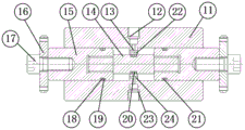
图2是图1中高压舱体部分的剖面示意图;Fig. 2 is a schematic sectional view of the hyperbaric cabin part in Fig. 1;
图3是测量相对运动时摩擦力的工作状态图;Fig. 3 is a working state diagram of friction force when measuring relative motion;
图4是测量相对运动时装配力的工作状态图。Figure 4 is a working state diagram of the assembly force when measuring relative motion.
图中:1电源;2控制端电脑;3恒温箱;4电源接口;5电机;6丝杠;7拉压力传感器;8抱箍;9高压舱系统;10速度控制器;11筒体;12排水接口;13排水通道;14第二滑轴;15第一滑轴;16法兰端面;17螺钉;18挡圈;19O型密封圈;20O型密封圈;21O型密封圈;22环形台阶;23进水接口;24进水通道。In the figure: 1 power supply; 2 control terminal computer; 3 constant temperature box; 4 power supply interface; 5 motor; Drainage interface; 13 drainage channel; 14 second sliding shaft; 15 first sliding shaft; 16 flange end face; 17 screw; 18 retaining ring; 19O sealing ring; 20O sealing ring; 21O sealing ring; 23 water inlet interface; 24 water inlet channel.
具体实施方式Detailed ways
以下的实施例可以使本专业技术领域的技术人员更全面的了解本发明,但不以任何方式限制本发明。The following examples can make those skilled in the technical field understand the present invention more comprehensively, but do not limit the present invention in any way.
本申请中为部件所编序号本身,例如“第一”、“第二”等,仅用于区分所描述的对象,不具有任何顺序或技术含义。而本申请所说“连接”、“联接”,如无特别说明,均包括直接和间接连接(联接)。在本申请的描述中,需要理解的是,术语“上”、“下”、“前”、“后”、“左”、“右”、“竖直”、“水平”、“顶”、“底”、“内”、“外”、“顺时针”、“逆时针”等指示的方位或位置关系为基于附图所示的方位或位置关系,仅是为了便于描述本申请和简化描述,而不是指示或暗示所指的装置或元件必须具有特定的方位、以特定的方位构造和操作,因此不能理解为对本申请的限制。The serial numbers for components in this application, such as "first", "second", etc., are only used to distinguish the described objects, and do not have any order or technical meaning. The "connection" and "connection" mentioned in this application all include direct and indirect connection (connection) unless otherwise specified. In the description of this application, it should be understood that the terms "upper", "lower", "front", "rear", "left", "right", "vertical", "horizontal", "top", The orientation or positional relationship indicated by "bottom", "inner", "outer", "clockwise", "counterclockwise", etc. is based on the orientation or positional relationship shown in the drawings, and is only for the convenience of describing the present application and simplifying the description , rather than indicating or implying that the device or element referred to must have a particular orientation, be constructed and operate in a particular orientation, and thus should not be construed as limiting the application.
在本申请中,除非另有明确的规定和限定,第一特征在第二特征“上”或“下”可以是第一和第二特征直接接触,或第一和第二特征通过中间媒介间接接触。而且,第一特征在第二特征“之上”、“上方”和“上面”可是第一特征在第二特征正上方或斜上方,或仅仅表示第一特征水平高度高于第二特征。第一特征在第二特征“之下”、“下方”和“下面”可以是第一特征在第二特征正下方或斜下方,或仅仅表示第一特征水平高度小于第二特征。In the present application, unless otherwise clearly specified and limited, a first feature being "on" or "under" a second feature may mean that the first and second features are in direct contact, or that the first and second features are indirect through an intermediary. touch. Moreover, "above", "above" and "above" the first feature on the second feature may mean that the first feature is directly above or obliquely above the second feature, or simply means that the first feature is higher in level than the second feature. "Below", "beneath" and "beneath" the first feature may mean that the first feature is directly below or obliquely below the second feature, or simply means that the first feature is less horizontally than the second feature.
本发明中,电源、控制端电脑、电机、丝杠、O型密封圈、拉压力传感器可以从市售产品里采购。抱箍、第一滑轴、第二滑轴、高压舱筒体等部件则可以按照实际需要进行加工即可。In the present invention, the power supply, the control terminal computer, the motor, the lead screw, the O-shaped sealing ring, and the tension and pressure sensor can be purchased from commercially available products. The hoop, first sliding shaft, second sliding shaft, hyperbaric chamber cylinder and other components can be processed according to actual needs.
如图1至4所示,本发明所述密封圈往复运动摩擦力及装配力的测试装置,包括温度控制系统、运动控制及拉压力测量系统、高压舱系统。其中,温度控制系统包括电源1、控制端电脑2和恒温箱3。运动控制及拉压力测量系统包括电机5、丝杠6和拉压力传感器7。电机5设有电源接口4和速度控制器10,分别通过线缆连接电源1和控制端电脑2。控制端电脑2通过调节电机5的转速来调节丝杆6往复直线运动的速度。丝杠6一端与电机输出端相连,另一端通过拉压力传感器7与高压舱系统9相连。运动控制及拉压力测量系统、高压舱系统9均安置在恒温箱3中。恒温箱3内部设有温度探头,恒温箱3的温度调控范围为0-50摄氏度,温度调控精度为0.1摄氏度。As shown in Figures 1 to 4, the test device for the reciprocating motion friction and assembly force of the sealing ring according to the present invention includes a temperature control system, a motion control and tension pressure measurement system, and a hyperbaric chamber system. Wherein, the temperature control system includes a
高压舱系统9包括中空的筒体11,筒体11中活动安装一个与之配合的滑轴组件;两个第一滑轴15将第二滑轴14固定夹持在中间,共同组成滑轴组件;在第一滑轴15的端部设置螺孔,在第二滑轴14的端部设置外螺纹,两者以螺接方式实现固定安装。第一滑轴15的外侧端部设置法兰端面16并由螺钉17实现固定,拉压力传感器7与法兰端面16固定连接。筒体11外侧设有至少两个抱箍8,抱箍8的底座通过螺钉固定在恒温箱3的底部。The
第二滑轴14的直径小于第一滑轴15,两个第一滑轴15的相对端部、第二滑轴外表面和筒体内壁共同围合形成加压水腔;在筒体11上设有连接加压水腔的进水通道24和排水通道13,在加压水腔中的筒体内壁上设有与第二滑轴14配合的环形台阶22;进水通道24和排水通道13呈T形布局,包括相连的横向贯通环形台阶22和沿径向布置的两部分通道,后者与设于筒体外壁上的进水接口23或排水接口12相连。The diameter of the second sliding
在第一滑轴15和第二滑轴14的外壁上分别设置环形槽,在各环形槽中分别嵌套设置O形密封圈19、21和20;各环形槽中还嵌套装有与O形密封圈并列的挡圈18。第一滑轴15与筒体11之间、第二滑轴14与环形台阶22之间均为过盈配合。On the outer walls of the first sliding
基于上述测试装置,本发明的密封圈往复运动摩擦力及装配力的测试方法,包括以下步骤:Based on the above-mentioned testing device, the test method of the sealing ring reciprocating motion friction force and assembly force of the present invention comprises the following steps:
(1)利用外部的增压泵向加压水腔中注水并增压,以模拟需要的海底水深压力;(1) Use an external booster pump to inject water into the pressurized water chamber and pressurize it to simulate the required seabed water depth pressure;
(2)通过控制端电脑2调节恒温箱3内的温度,使高压舱系统9降至模拟的海底温度;(2) adjust the temperature in the
(3)利用电机5驱动丝杠6,带动第一滑轴15向一侧位移,获得拉压力传感器7的稳定读数;该数值由两个第一滑轴15上的O型密封圈19、21与筒体11之间的摩擦阻力F、以及第二滑轴14上的O型密封20与环形台阶22之间的摩擦阻力f组成,表示为:2F+f1;(3) Utilize
(4)继续驱动第一滑轴15向同侧位移,使第二滑轴14上的O型密封圈与环形台阶22脱离接触后,获得拉压力传感器7的稳定读数;该数值由两个第一滑轴15上的O型密封圈19、21与筒体之间的摩擦阻力F组成,表示为:2F;(4) Continue to drive the first sliding
(5)根据步骤(3)、(4),求解得到两种O型密封圈的摩擦阻力F、f1的数值;(5) according to steps (3), (4), solve the numerical value that obtains the frictional resistance F, f of two kinds of O-shaped sealing rings;
(6)利用电机5反向驱动丝杠6,带动第一滑轴15反向位移,使第二滑轴14上的O型密封圈20从与环形台阶22刚好接触继续运动到与其形成密封配合,获得该过程中拉压力传感器7的最大读数;该数值由两个第一滑轴15上的O型密封圈19、21与筒体11之间的摩擦阻力F、以及第二滑轴14上的O型密封20与环形台阶22之间的装配力f2组成,表示为:2F+f2;(6) Utilize the
(7)利用步骤(5)的计算结果和步骤(6)的测量结果,求解得到第二滑轴14上的O型密封20与环形台阶22之间的装配力f2的数值。(7) Using the calculation result of step (5) and the measurement result of step (6), solve to obtain the numerical value of the assembly force f 2 between the O-
更为详细的示例如下:A more detailed example follows:
首先将电机5的电源接口4与电源2相连,速度控制器10与控制端电脑2连接。通过控制端电脑2使电机5转动并带动丝杆6做直线运动,丝杆6带动滑轴组件做直线运动。控制丝杆6的位移,将第二滑轴14及第一滑轴15居中放置,如图2所示。此时第二滑轴14的O型密封圈20与环形台阶22接触。将外部的增压泵连接到进水接口23,其增压范围为0-120MPa。在排水接口12处连接针阀并打开,启动增压泵给加压水腔充水,当排水接口12处有水溢出时,关闭针阀。继续通过增压泵提升加压水腔的内部压力,直至达到需要模拟的水深压力。First, connect the
高压舱系统整体置于恒温箱3中,并通过控制端电脑2调节温度至需要模拟水深的温度,其温度调节范围为0-50摄氏度,温度调控精度为0.1摄氏度。高压舱系统在恒温箱3中放置12小时以上,保证其任意部分达到均一的温度。The hyperbaric chamber system is placed in the
启动电机5,丝杠6推动滑轴组件向左移动,拉压力传感器7稳定时的数值由两个O型密封圈19、21与筒体11之间的摩擦阻力F、以及O型密封20与环形台阶22之间的摩擦阻力f1组成,故拉压力传感器7稳定时的数值表示为式(1):Start the
2F+f1(1)2F+f 1 (1)
丝杠6继续推动滑轴组件向左运动,当O型密封圈20与环形台阶22脱离接触后,如图3所示,拉压力传感器7测得稳定时的数值由O型密封圈19、21与筒体11之间的摩擦阻力F组成,故拉压力传感器稳定时的数值表示为式(2)Lead
2F(2)2F(2)
式(1)与式(2)构成封闭的方程组,此时可求出O型密封圈19或21与耐筒体11之间的摩擦阻力F以及小直径O型密封圈20与台阶22之间的摩擦阻力f1。Formula (1) and formula (2) form a closed equation group. At this time, the frictional resistance F between the O-
反向运转电机5,丝杠6推动滑轴组件向右移动,使O型密封圈20从加压水腔(图3所示)运动到与环形台阶22刚好接触(图4所示),并继续运动到与环形台阶22形成密封配合(图2所示)。该过程中拉压力传感器7数值的最大值由O型密封圈一19、21与筒体11之间的摩擦阻力F以及O型密封圈20与环形台阶22之间装配力f2组成,故拉压力传感器最大值为式(3)Rotate the
2F+f2(3)2F+f 2 (3)
结合式(2)以及式(3),可求得O型密封圈20与环形台阶22之间装配力f2。Combining formula (2) and formula (3), the assembly force f 2 between the O-
最后,需要注意的是,以上列举的仅是本发明的具体实施例。显然,本发明不限于以上实施例,还可以有很多变形。可以通过对O型密封圈材料和线径的调整以及加工不同材料、直径的滑轴组件和筒体,来实现多不同型号O型密封圈的摩擦阻力及装配阻力的测量。本领域的普通技术人员能从本发明公开的内容中直接导出或联想到的所有变形,均应认为是本发明的保护范围。Finally, it should be noted that what is listed above are only specific embodiments of the present invention. Obviously, the present invention is not limited to the above embodiments, and many modifications are possible. The measurement of friction resistance and assembly resistance of many different types of O-rings can be realized by adjusting the material and wire diameter of the O-rings and processing sliding shaft assemblies and cylinders of different materials and diameters. All deformations that can be directly derived or associated by those skilled in the art from the content disclosed in the present invention should be considered as the protection scope of the present invention.
Claims (10)
Priority Applications (1)
| Application Number | Priority Date | Filing Date | Title |
|---|---|---|---|
| CN202111532201.2A CN114199552B (en) | 2021-12-14 | 2021-12-14 | Device and method for testing reciprocating motion friction force and assembly force of sealing ring |
Applications Claiming Priority (1)
| Application Number | Priority Date | Filing Date | Title |
|---|---|---|---|
| CN202111532201.2A CN114199552B (en) | 2021-12-14 | 2021-12-14 | Device and method for testing reciprocating motion friction force and assembly force of sealing ring |
Publications (2)
| Publication Number | Publication Date |
|---|---|
| CN114199552A CN114199552A (en) | 2022-03-18 |
| CN114199552B true CN114199552B (en) | 2023-03-31 |
Family
ID=80653968
Family Applications (1)
| Application Number | Title | Priority Date | Filing Date |
|---|---|---|---|
| CN202111532201.2A Active CN114199552B (en) | 2021-12-14 | 2021-12-14 | Device and method for testing reciprocating motion friction force and assembly force of sealing ring |
Country Status (1)
| Country | Link |
|---|---|
| CN (1) | CN114199552B (en) |
Family Cites Families (7)
| Publication number | Priority date | Publication date | Assignee | Title |
|---|---|---|---|---|
| CN101963534A (en) * | 2010-09-07 | 2011-02-02 | 青岛开世密封工业有限公司 | Tension test system and method for testing press-in force and pull-out force of skeleton sealing ring thereof |
| CN104535243B (en) * | 2015-01-08 | 2017-01-18 | 清华大学 | Reciprocating seal experiment table for measuring friction feature of single seal ring |
| CN106353080B (en) * | 2016-08-30 | 2019-02-15 | 中国海洋大学 | A kind of experimental device and experimental method for linear dynamic sealing characteristics of sealing ring |
| CN110044532B (en) * | 2019-04-20 | 2020-04-28 | 清华大学 | A reciprocating sealing experimental cylinder structure that can measure the friction force of a single sealing ring |
| CN110296829A (en) * | 2019-07-03 | 2019-10-01 | 清华大学 | A kind of high-voltage high-speed reciprocation sealing experiment test platform |
| CN110514338B (en) * | 2019-09-05 | 2020-09-15 | 清华大学 | A high-pressure and high-speed reciprocating sealing experimental test platform with floating cylinder |
| CN112683522A (en) * | 2020-11-18 | 2021-04-20 | 南京航空航天大学 | Device and method for measuring friction force of sealing ring under given pressure |
-
2021
- 2021-12-14 CN CN202111532201.2A patent/CN114199552B/en active Active
Also Published As
| Publication number | Publication date |
|---|---|
| CN114199552A (en) | 2022-03-18 |
Similar Documents
| Publication | Publication Date | Title |
|---|---|---|
| Pan et al. | Experimental investigation of friction behaviors for double-acting hydraulic actuators with different reciprocating seals | |
| CN104132805B (en) | A kind of Multifunctional pneumatic power reciprocation sealing performance test stand | |
| CN112924300A (en) | Deep ultra-deep rock high temperature-seepage-stress-chemical coupling test system | |
| CN109870349A (en) | A high temperature and high pressure hydraulic fracturing holder and its test method | |
| CN105241809A (en) | O-shaped ring friction experiment apparatus | |
| CN102135478A (en) | Triaxial test device for testing transubstantiation of sediments of gas hydrate | |
| CN208999037U (en) | Products air tightness detection device and its detection system | |
| CN111174985A (en) | Filler sealing performance detection device | |
| CN113295540A (en) | Triaxial test device containing natural gas hydrate sediment | |
| CN105628364B (en) | Controllable flexible sealing performance detection test device | |
| CN114199552B (en) | Device and method for testing reciprocating motion friction force and assembly force of sealing ring | |
| CN206804196U (en) | A kind of fired state lower piston component and cylinder sleeve friction testing device | |
| CN114739563B (en) | A mechanical seal radial film pressure distribution testing device with a movable static ring | |
| CN2896257Y (en) | Multi-parameter measurable and controllable high-speed mechanical seal performance test device | |
| CN108398325A (en) | Test the acoustic response experimental rig of rock | |
| CN108869457B (en) | A reciprocating sealing device to study the effect of piston rod eccentricity on the performance of seals | |
| CN103760095A (en) | Sliding-table bushing abrasion machine | |
| CN101782092B (en) | Test method of lowest starting pressure of hydraulic executing component | |
| US12480852B2 (en) | Pretension and tensile impact test apparatus capable of simulating full-sea-depth environment | |
| CN203163968U (en) | Non-metal O-shaped ring performance testing device | |
| CN112213027A (en) | Rapid calibrating device and calibrating method for pressure sensor | |
| CN116124338A (en) | Device and method for measuring axial force of sealing element | |
| CN108332959A (en) | A kind of high/low temperature sealing test experimental bench | |
| CN209164244U (en) | A reciprocating sealing device to study the effect of piston rod eccentricity on the performance of seals | |
| US3930403A (en) | Piston assembly |
Legal Events
| Date | Code | Title | Description |
|---|---|---|---|
| PB01 | Publication | ||
| PB01 | Publication | ||
| SE01 | Entry into force of request for substantive examination | ||
| SE01 | Entry into force of request for substantive examination | ||
| GR01 | Patent grant | ||
| GR01 | Patent grant |