CN114195295B - Oily wastewater treatment device of coking emptying tower - Google Patents
Oily wastewater treatment device of coking emptying tower Download PDFInfo
- Publication number
- CN114195295B CN114195295B CN202210141929.0A CN202210141929A CN114195295B CN 114195295 B CN114195295 B CN 114195295B CN 202210141929 A CN202210141929 A CN 202210141929A CN 114195295 B CN114195295 B CN 114195295B
- Authority
- CN
- China
- Prior art keywords
- wall
- pipe
- settling tank
- stirring
- fixed mounting
- Prior art date
- Legal status (The legal status is an assumption and is not a legal conclusion. Google has not performed a legal analysis and makes no representation as to the accuracy of the status listed.)
- Active
Links
Images


Classifications
-
- C—CHEMISTRY; METALLURGY
- C02—TREATMENT OF WATER, WASTE WATER, SEWAGE, OR SLUDGE
- C02F—TREATMENT OF WATER, WASTE WATER, SEWAGE, OR SLUDGE
- C02F9/00—Multistage treatment of water, waste water or sewage
-
- C—CHEMISTRY; METALLURGY
- C02—TREATMENT OF WATER, WASTE WATER, SEWAGE, OR SLUDGE
- C02F—TREATMENT OF WATER, WASTE WATER, SEWAGE, OR SLUDGE
- C02F1/00—Treatment of water, waste water, or sewage
- C02F1/001—Processes for the treatment of water whereby the filtration technique is of importance
-
- C—CHEMISTRY; METALLURGY
- C02—TREATMENT OF WATER, WASTE WATER, SEWAGE, OR SLUDGE
- C02F—TREATMENT OF WATER, WASTE WATER, SEWAGE, OR SLUDGE
- C02F1/00—Treatment of water, waste water, or sewage
- C02F1/40—Devices for separating or removing fatty or oily substances or similar floating material
-
- C—CHEMISTRY; METALLURGY
- C02—TREATMENT OF WATER, WASTE WATER, SEWAGE, OR SLUDGE
- C02F—TREATMENT OF WATER, WASTE WATER, SEWAGE, OR SLUDGE
- C02F1/00—Treatment of water, waste water, or sewage
- C02F1/52—Treatment of water, waste water, or sewage by flocculation or precipitation of suspended impurities
- C02F1/5281—Installations for water purification using chemical agents
-
- C—CHEMISTRY; METALLURGY
- C02—TREATMENT OF WATER, WASTE WATER, SEWAGE, OR SLUDGE
- C02F—TREATMENT OF WATER, WASTE WATER, SEWAGE, OR SLUDGE
- C02F2209/00—Controlling or monitoring parameters in water treatment
- C02F2209/11—Turbidity
-
- C—CHEMISTRY; METALLURGY
- C02—TREATMENT OF WATER, WASTE WATER, SEWAGE, OR SLUDGE
- C02F—TREATMENT OF WATER, WASTE WATER, SEWAGE, OR SLUDGE
- C02F2303/00—Specific treatment goals
- C02F2303/16—Regeneration of sorbents, filters
-
- Y—GENERAL TAGGING OF NEW TECHNOLOGICAL DEVELOPMENTS; GENERAL TAGGING OF CROSS-SECTIONAL TECHNOLOGIES SPANNING OVER SEVERAL SECTIONS OF THE IPC; TECHNICAL SUBJECTS COVERED BY FORMER USPC CROSS-REFERENCE ART COLLECTIONS [XRACs] AND DIGESTS
- Y02—TECHNOLOGIES OR APPLICATIONS FOR MITIGATION OR ADAPTATION AGAINST CLIMATE CHANGE
- Y02W—CLIMATE CHANGE MITIGATION TECHNOLOGIES RELATED TO WASTEWATER TREATMENT OR WASTE MANAGEMENT
- Y02W10/00—Technologies for wastewater treatment
- Y02W10/10—Biological treatment of water, waste water, or sewage
Abstract
The invention relates to the technical field of emptying tower sump oil recycling, in particular to a coking emptying tower oily wastewater treatment device, which comprises a settling tank, wherein the outer wall of a filter plate is provided with a cleaning mechanism, the top end of an output shaft of a stirring motor is provided with a stirring mechanism, the stirring mechanism is arranged on the inner wall of a flocculation tank, and the top of the settling tank is provided with a grading mechanism. Thereby improving the flocculation effect.
Description
Technical Field
The invention relates to the technical field of sump oil recycling of an emptying tower, in particular to an oily wastewater treatment device of a coking emptying tower.
Background
In order to ensure the safe operation of the recycled sump oil and the stable production of coking, part of the sump oil produced by a company needs to be recycled in a coking emptying tower, the device is needed to be used for treating the oily wastewater of the coking emptying tower, the oily wastewater of the coking emptying tower mainly refers to blowing condensed water and small feed water coke cooling water, is rich in various malodorous gases which are easy to volatilize, the wastewater is one of the most difficult-to-treat coking oily wastewater in refineries, the delayed coking device is a main processing device for improving the yield of light oil and producing petroleum coke in refineries and is also one of the main devices for deeply processing residual oil and heavy oil at present, as the prior art has the methods for treating the oily wastewater including a gravity separation method, a filtration method, an air floatation method, a microbiological method, a cyclone separation method and the like, although these methods have a certain treatment effect, it is difficult to satisfy the economic and technical requirements of the deep purification treatment.
The Chinese patent publication for solving the problems is as follows: the patent of CN109081479A provides a device and a method for treating oily wastewater in a coking emptying tower, which comprises a raw water storage tank, a coalescer, a membrane separator, a micro-electrolysis reactor and a settling tank, can realize the purification treatment of the oily wastewater and the sufficient collection of recovered oil products, and the oily wastewater in the coking emptying tower can be used as cold coke water of small feed water for recycling after fine oil removal and can also be used or discharged into a sewage treatment plant after acid stripping.
However, the following problems still exist in the prior art:
(1) the existing settling tank for treating the oily wastewater performs flocculation settling on the sewage through a flocculating agent, but most flocculating agents generally require about 1 hour of stirring time to fully dissolve powder, if the flocculating agents are not fully mixed or agglomerate, the performance of the flocculating agents can be influenced, and even sedimentation and blockage of pipelines and pumps can be generated, the ideal rotating speed of the stirring speed during the dissolving of the flocculating agents is 200-400 revolutions per minute, if the stirring speed is too high, molecules of the flocculating agents can be damaged, the existing device has a single step of dissolving the flocculating agents, the stirring degree can not be regulated according to the flocculation condition, the flocculation effect of the settling tank is influenced, and certain limitations exist;
(2) when the clear water after the prior art will be handled is taken out, the bottom position that the clear water was taken out the pipe can not be adjusted, and can not keep the clear water to take out the bottom position that the pipe just is located the high water layer that clear water layer turbidity is minimum, leads to the clear water turbidity of finally taking out higher, has reduced the holistic hierarchical effect of device.
Disclosure of Invention
The invention aims to provide a device for treating oily wastewater of a coking emptying tower, which solves the problems in the background technology.
The technical scheme of the invention is as follows: a coking emptying tower oily wastewater treatment device comprises a settling tank, wherein a flocculation tank is fixedly arranged on the inner wall of the settling tank, an opening is formed in the bottom of the flocculation tank, a filter plate is fixedly arranged between the outer wall of the flocculation tank and the inner wall of the settling tank, a cleaning mechanism is arranged on the outer wall of the filter plate, a secondary filtering extraction pipe, a water inlet pipe and a clear water extraction pipe are sleeved on the outer wall of the top of the settling tank, a mounting frame is fixedly arranged on the outer wall of the top of the settling tank, a stirring motor is fixedly arranged on the outer wall of the bottom of the mounting frame, a stirring mechanism is arranged at the top end of an output shaft of the stirring motor and is arranged on the inner wall of the flocculation tank, a grading mechanism is arranged at the top of the settling tank, a flocculating agent injection pipe is sleeved on the top of the settling tank, an auxiliary blanking mechanism is arranged on the inner wall of the flocculating agent injection pipe, and a turbidity detection component is arranged on the inner circumferential wall of the settling tank, the turbidity detection component comprises a turbidity sensor, and a slag discharge pipe is arranged at the bottom of the settling tank.
Preferably, turbidity detects the part including fixed mounting in the curb plate of settling tank circumference outer wall one side, the mounting hole has been seted up to the outer wall of curb plate and settling tank, turbidity sensor fixed mounting is in the inner wall of mounting hole, turbidity sensor is provided with a plurality ofly, and is a plurality of turbidity sensor is circumference array distribution, circumference outer wall one side of settling tank is provided with display panel, the controller is installed to one side outer wall of display panel, the controller passes through electric connection with turbidity sensor.
Preferably, the middle of the clean water pumping pipe is disconnected and provided with a hose, one end of the clean water pumping pipe is fixedly provided with a fixed plate, one side of the fixed plate is inserted into the inner wall of the circumference of the settling box in a sliding manner, the outer wall of the top of the fixed plate is provided with a threaded hole, the inner wall of the threaded hole is connected with a lead screw through a thread, the outer wall of the top of the settling box is fixedly provided with a height adjusting motor, the top end of an output shaft of the height adjusting motor is fixedly connected with the top end of the lead screw, and the height adjusting motor is electrically connected with the controller.
Preferably, rabbling mechanism sets up in the dead eye of settling tank top outer wall, and the inner wall of dead eye is connected with the ratchet cover through the bearing, the bottom of ratchet cover is provided with the fluted disc, agitator motor's output shaft fixed mounting has the pivot, the pivot cup joints in the inner wall of ratchet cover, and the outer wall of pivot and the inner wall meshing of ratchet cover, the outer wall fixed mounting of pivot has the mounting panel, the outer wall rotation of mounting panel is connected with the worm, the top of worm is provided with the pinion, the outer wall of pinion and the outer wall meshing of fluted disc, the circumference outer wall of pivot rotates and is connected with the turbine, one side outer wall fixed mounting of turbine has a plurality of puddlers, and is a plurality of fixed mounting has the stirring board between the puddler, the rabbling mechanism sets up the inner wall that is located the flocculation tank.
Preferably, the grading mechanism comprises an adjusting ratchet wheel fixedly mounted on the top end of the outer wall of the ratchet sleeve, the outer wall of the top of the settling box is fixedly mounted with a grading motor, the top end of an output shaft of the grading motor is fixedly mounted with a large gear, and the large gear is meshed with the adjusting ratchet wheel.
Preferably, supplementary unloading mechanism is including setting up the spiral delivery sheet that is located flocculating agent notes pipe inner wall, the top inner wall fixed mounting of setting bin has the support, the top outer wall of support rotates and is connected with thin axle, thin axle runs through with the support, spiral delivery sheet fixed mounting is in the outer wall of thin axle, the bottom fixed mounting of thin axle has drive fan blade.
Preferably, the bottom of secondary filter extraction pipe is provided with flexible pipe, and the pipe that absorbs water that is flat shape has been cup jointed to flexible pipe's bottom, the pipe that absorbs water be provided with two water inlets, the outer wall that absorbs water the pipe is provided with the foam blanket, and the one side outer wall fixed mounting who absorbs water the pipe has the slide, the slide opening that runs through is seted up to the top outer wall of slide, the inner wall of slide opening slides and pegs graft there is the slide bar, and one side of slide slides and pegs graft in the inner wall of setting chest, the both ends of slide bar are fixed mounting respectively in the bottom inner wall of setting chest and the circumference inner wall one side of setting chest.
Preferably, the cleaning mechanism includes the scraper blade, the outer wall of scraper blade is provided with the brush hair that distributes evenly, the scraper blade is provided with two, the bottom fixed mounting of pivot has the connecting rod, two the equal fixed mounting of scraper blade is in the bottom of connecting rod, the cleaning mechanism sets up in the bottom of filter.
Preferably, the bottom end of the water inlet pipe is connected with a spiral pipe, and the spiral pipe is downward in a spiral shape.
The invention provides a coking emptying tower oily wastewater treatment device through improvement, and compared with the prior art, the coking emptying tower oily wastewater treatment device has the following improvements and advantages:
one is as follows: according to the invention, the large gear is driven to rotate by starting the level-adjusting motor, so that the adjusting ratchet is driven to rotate, the ratchet sleeve arranged on the inner wall of the adjusting ratchet rotates, the worm is driven to rotate by meshing of the fluted disc and the small gear, the worm drives the turbine to rotate by meshing of the worm and the turbine, and further the inclination angles of the stirring rod and the stirring plate are changed, so that the impact and cutting effects on sewage are changed, the stirring rod and the stirring plate can be adjusted to the optimal inclination angle in time according to the flocculation condition, the flocculant molecules can be prevented from being damaged due to too large stirring amplitude, the situation that the flocculant is dissolved insufficiently due to too small stirring amplitude can be prevented, and the flocculation effect is effectively improved;
the second step is as follows: the multiple turbidity sensors can monitor the sewage turbidity in the area between the inner wall of the settling tank and the outer wall of the flocculation tank, and the water pumping end of the clear water pumping pipe is adjusted to the depth of the water layer for pumping according to the monitoring results of the turbidity sensors at different positions, so that the clear water can be pumped out to the maximum extent, the untreated sewage is prevented from being pumped out, and the grading treatment effect of the device is improved;
and thirdly: when the water in the flocculation tank is disturbed, the water flow drives the driving fan blades to rotate, so that the thin shaft rotates at the moment, the spiral feeding plate rotates, the flocculant in the flocculant injection pipe can be conveyed downwards, the situation that the flocculant is blocked due to the fact that the sewage splashes at the outlet of the flocculant injection pipe when being stirred is avoided, and the interference on the discharging process of the flocculant is avoided;
fourthly, the method comprises the following steps: the bottom end of the water inlet pipe is connected with the spiral pipe, the spiral pipe is in a spiral shape downward, so that the entering sewage generates a rotating centrifugal force, the rotating direction of the spiral pipe is opposite to that of the stirring rod and the stirring plate, and the entering sewage and the flowing sewage on the inner wall of the flocculation box generate an impact effect, so that the fusion effect of a flocculating agent and the sewage is further improved, and the sewage treatment effect of the flocculating agent is further improved;
and fifthly: according to the invention, the foam layer arranged on the outer wall of the water suction pipe can enable the water suction port of the water suction pipe to be always kept at the top of the sewage liquid level, and the water suction pipe slides along the outer wall of the sliding rod through the sliding plate, so that fine oil stains and impurities floating on the liquid level can be pumped away through the water suction pipe, the fine oil stains are collected, and then the sewage is pumped into the filtering device again through the secondary filtering and pumping pipe for retreatment.
Drawings
The invention is further explained below with reference to the figures and examples:
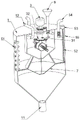
FIG. 1 is a first perspective view of the present invention;
FIG. 2 is a perspective view of the present invention from a second perspective;
FIG. 3 is a perspective view of a first cross-sectional view of the present invention;
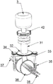
FIG. 4 is a perspective view of a portion of the stirring mechanism of the present invention;
figure 5 is a perspective view of the internal structure of the settling tank of the present invention;
FIG. 6 is a perspective view of the internal structure of a flocculant injection pipe of the present invention;
FIG. 7 is a perspective view of a second cross-sectional view of the present invention;
FIG. 8 is a perspective view of a third cross-sectional view of the present invention.
Description of reference numerals:
1. a settling tank; 2. a mounting frame; 3. a stirring motor; 31. a ratchet sleeve; 32. a fluted disc; 33. mounting a plate; 34. a pinion gear; 35. a worm; 36. a turbine; 37. a stirring rod; 38. a stirring plate; 4. a step-adjusting motor; 41. a bull gear; 42. adjusting the ratchet wheel; 5. a side plate; 51. a turbidity sensor; 52. a screw rod; 53. a height adjustment motor; 54. pumping out clean water; 55. a fixing plate; 6. secondary filtering and pipe drawing; 61. a suction pipe; 62. a slide plate; 63. a slide bar; 7. a squeegee; 71. a connecting rod; 8. a filter plate; 9. injecting a flocculating agent; 91. a support; 92. a thin shaft; 93. a screw feeding plate; 94. driving the fan blades; 10. a display panel; 11. a slag discharge pipe; 12. a water inlet pipe; 13. and a flocculation box.
Detailed Description
The present invention is described in detail below, and technical solutions in the embodiments of the present invention are clearly and completely described, and it is obvious that the described embodiments are only a part of the embodiments of the present invention, and not all of the embodiments. All other embodiments, which can be derived by a person skilled in the art from the embodiments given herein without making any creative effort, shall fall within the protection scope of the present invention.
The invention provides a device for treating oily wastewater of a coking emptying tower by improvement, which adopts the technical scheme that:
as shown in figures 1-8, a coking emptying tower oily wastewater treatment device comprises a settling tank 1, a flocculation tank 13 is fixedly installed on the inner wall of the settling tank 1, an opening is formed in the bottom of the flocculation tank 13, a filter plate 8 is fixedly installed between the outer wall of the flocculation tank 13 and the inner wall of the settling tank 1, a cleaning mechanism is arranged on the outer wall of the filter plate 8, a secondary filtering extraction pipe 6, a water inlet pipe 12 and a clear water extraction pipe 54 are sleeved on the outer wall of the top of the settling tank 1, a mounting frame 2 is fixedly installed on the outer wall of the top of the settling tank 1, a stirring motor 3 is fixedly installed on the outer wall of the bottom of the mounting frame 2, a stirring mechanism is arranged at the top end of an output shaft of the stirring motor 3 and is arranged on the inner wall of the flocculation tank 13, a grading mechanism is arranged on the top of the settling tank 1, a flocculating agent injection pipe 9 is sleeved on the top of the settling tank 1, and an auxiliary blanking mechanism is arranged on the inner wall of the flocculating agent injection pipe 9, the circumference inner wall that subsides case 1 is provided with turbidity detection part, and turbidity detection part includes turbidity sensor 51, and the bottom that subsides case 1 is provided with row sediment pipe 11, and the lump form impurity after the flocculation flows out flocculation case 13, finally discharges from row sediment pipe 11.
Further, the turbidity detection part comprises a side plate 5 fixedly installed on one side of the outer wall of the circumference of the settling tank 1, the side plate 5 and the outer wall of the settling tank 1 are provided with installation holes, a plurality of turbidity sensors 51 are fixedly installed on the inner wall of the installation holes, the turbidity sensors 51 are arranged, the plurality of turbidity sensors 51 are distributed in a circumferential array, one side of the outer wall of the circumference of the settling tank 1 is provided with a display panel 10, one side of the outer wall of the display panel 10 is provided with a controller, the controller is electrically connected with the turbidity sensors 51, the plurality of turbidity sensors 51 can monitor the sewage turbidity in the area between the inner wall of the settling tank 1 and the outer wall of the flocculation tank 13, according to the monitoring results of the turbidity sensors 51 at different positions, the water pumping end of the clear water pumping pipe 54 is adjusted to the depth of the water layer for pumping, the clear water can be pumped out to the maximum extent, and the untreated sewage is prevented from being pumped out, the grading treatment effect of the device is improved.
Further, the centre disconnection of clear water exhaust pipe 54 and be provided with the hose, the one end fixed mounting of clear water exhaust pipe 54 has fixed plate 55, one side of fixed plate 55 slides and pegs graft in the circumference inner wall of setting tank 1, the top outer wall of fixed plate 55 sets up threaded hole, the inner wall of threaded hole has lead screw 52 through threaded connection, the top outer wall fixed mounting of setting tank 1 has height adjusting motor 53, height adjusting motor 53's output shaft top and the top fixed connection of lead screw 52, height adjusting motor 53 and controller electric connection, the controller can each position turbidity sensor 51's of automatic analysis numerical value then starts height adjusting motor 53 and drives lead screw 52 and rotate, finally, the rotation through lead screw 52 drives fixed plate 55 and slides to the minimum turbid water layer position.
Furthermore, the stirring mechanism is arranged in a bearing hole formed in the outer wall of the top of the settling tank 1, the inner wall of the bearing hole is connected with a ratchet sleeve 31 through a bearing, a fluted disc 32 is arranged at the bottom end of the ratchet sleeve 31, a rotating shaft is fixedly arranged on an output shaft of the stirring motor 3, the rotating shaft is sleeved on the inner wall of the ratchet sleeve 31, the outer wall of the rotating shaft is meshed with the inner wall of the ratchet sleeve 31, a mounting plate 33 is fixedly arranged on the outer wall of the rotating shaft, a worm 35 is rotatably connected with the outer wall of the mounting plate 33, a pinion 34 is arranged at the top of the worm 35, the outer wall of the pinion 34 is meshed with the outer wall of the fluted disc 32, a turbine 36 is rotatably connected with the outer wall of the circumference of the rotating shaft, a plurality of stirring rods 37 are fixedly arranged on the outer wall of one side of the turbine 36, a stirring plate 38 is fixedly arranged among the plurality of stirring rods 37, the stirring mechanism is arranged on the inner wall of the flocculation tank 13, the stirring motor 3 is started to drive the rotating shaft to rotate, and further drive the stirring rods 37 and the stirring plate 38 to rotate around the rotating shaft as a center, at this moment, the turbine 36 does not rotate, the rotating shaft rotates while driving the ratchet sleeve 31 to rotate, relative rotation between the worm 35 and the turbine 36 can be avoided, meanwhile, the worm 35 can lock the turbine 36, the inclination angles of the stirring rod 37 and the stirring plate 38 are fixed, the inclination angles of the stirring rod 37 and the stirring plate 38 are prevented from being changed under water flow impact, and the flocculant can be stirred by the stirring rod 37 and the stirring plate 38 to accelerate the dissolution of the flocculant when the flocculant is filled.
Furthermore, the grading mechanism comprises an adjusting ratchet wheel 42 fixedly mounted on the top end of the outer wall of the ratchet sleeve 31, a grading motor 4 is fixedly mounted on the outer wall of the top of the settling tank 1, a large gear 41 is fixedly mounted on the top end of an output shaft of the grading motor 4, the large gear 41 is meshed with the adjusting ratchet wheel 42, the grading motor 4 is started to drive the large gear 41 to rotate, and further drive the adjusting ratchet wheel 42 to rotate, the ratchet sleeve 31 arranged on the inner wall of the adjusting ratchet wheel 42 rotates, the worm 35 is driven to rotate through the meshing of the fluted disc 32 and the small gear 34, the worm 35 drives the turbine 36 to rotate through the meshing of the turbine 36, and further the inclination angles of the stirring rod 37 and the stirring plate 38 are changed, so that the impact and cutting effects on the sewage are changed, the regulation can be timely performed according to the flocculation condition, and the stirring rod 37 and the stirring plate 38 can be regulated to the optimal inclination angle, can avoid stirring range too big destruction flocculating agent molecule, can prevent again that the too little condition that leads to the flocculating agent to dissolve insufficient emergence of stirring range, and then effectual promotion flocculation effect.
Further, supplementary unloading mechanism is including setting up the spiral delivery sheet 93 that is located 9 inner walls of flocculating agent notes pipe, the top inner wall fixed mounting of setting box 1 has support 91, the top outer wall of support 91 rotates and is connected with thin axle 92, thin axle 92 runs through with support 91, spiral delivery sheet 93 fixed mounting is in the outer wall of thin axle 92, the bottom fixed mounting of thin axle 92 has drive flabellum 94, when the water in flocculation box 13 takes place the disturbance, rivers drive flabellum 94 and rotate, make thin axle 92 of this moment take place to rotate, thereby make spiral delivery sheet 93 rotate, can downwards carry the flocculating agent in the flocculating agent notes pipe 9, the condition of splashing in the exit of flocculating agent notes pipe 9 when avoiding because sewage stirs causes the flocculating agent to block up takes place, avoid causing the interference to the unloading process of flocculating agent.
Furthermore, the bottom end of the secondary filtering suction pipe 6 is provided with an extension pipe, the bottom end of the extension pipe is sleeved with a flat-shaped water suction pipe 61, the water suction pipe 61 is provided with two water inlets, the outer wall of the water suction pipe 61 is provided with a foam layer, the outer wall of one side of the water suction pipe 61 is fixedly provided with a sliding plate 62, the outer wall of the top of the sliding plate 62 is provided with a through sliding hole, the inner wall of the sliding hole is slidably inserted with a sliding rod 63, one side of the sliding plate 62 is slidably inserted in the inner wall of the settling box 1, two ends of the sliding rod 63 are respectively and fixedly arranged on the inner wall of the bottom of the settling box 1 and one side of the inner wall of the circumference of the settling box 1, the foam layer can enable the water suction port of the water suction pipe 61 to be always kept at the top of the sewage liquid level, the water suction pipe 61 slides along the outer wall of the sliding rod 63 through the sliding plate 62, so that fine oil stains and impurities floating on the liquid level can be sucked through the water suction pipe 61, and the fine oil stains can be collected, then the sewage is pumped into the filtering device again through the secondary filtering pumping pipe 6 for treatment again.
Further, clearance mechanism includes scraper blade 7, the outer wall of scraper blade 7 is provided with the even brush hair of distribution, scraper blade 7 is provided with two, the bottom fixed mounting of pivot has connecting rod 71, the equal fixed mounting of two scraper blades 7 in connecting rod 71's bottom, clearance mechanism sets up in filter 8's bottom, in-process at flocculation treatment, can drive connecting rod 71 through the pivot and rotate, and then the brush that drives scraper blade 7 outer wall scrapes the outer wall of filter 8, avoid impurity, the lump after the flocculation plugs up the mesh of filter 8, make the flocculation step can be long-time going on continuously, reduce the maintenance time, promote the operating efficiency.
Further, the bottom of inlet tube 12 is connected with the spiral pipe, and the shape of spiral pipe is for being the downward this shape design of spiral shape for the sewage that gets into produces pivoted centrifugal force, and this direction is opposite with the rotation direction of puddler 37 and stirring board 38, and the sewage that gets into this moment and the sewage of the flow of flocculation case 13 inner wall produce the effect of striking, thereby further promote the integration effect of flocculating agent and sewage, and then promote the treatment effect to the flocculating agent to sewage.
The working principle is as follows: when the oily wastewater in the coking emptying tower is treated, the wastewater enters the settling tank 1 through the water inlet pipe 12 after being subjected to multistage filtration, at the moment, a prepared flocculating agent is filled through the flocculating agent filling pipe 9, the stirring motor 3 is started to drive the rotating shaft to rotate at the same time, the stirring rod 37 and the stirring plate 38 are driven to rotate circularly around the rotating shaft as the center, the turbine 36 does not rotate at the moment, the ratchet sleeve 31 is driven to rotate while the rotating shaft rotates, so that the relative rotation between the worm 35 and the turbine 36 can be avoided, meanwhile, the worm 35 can lock the turbine 36, the inclination angles of the stirring rod 37 and the stirring plate 38 are fixed, the inclination angles of the stirring rod 37 and the stirring plate 38 are prevented from being changed under the impact of water flow, the dissolving of the flocculating agent can be accelerated through the stirring generated by the stirring rod 37 and the stirring plate 38 when the flocculating agent is filled, and the grading motor 4 can be started to drive the large gear 41 to rotate, and then drive the regulation ratchet 42 and rotate, the ratchet cover 31 that the inner wall of this moment of regulation ratchet 42 set up rotates, the meshing through fluted disc 32 and pinion 34 drives worm 35 to rotate, worm 35 drives turbine 36 rotation through the meshing with turbine 36 this moment, and then make the inclination of puddler 37 and stirring board 38 change, thereby make the impact and the cutting effect to sewage change, can in time adjust according to the condition of flocculation, make puddler 37 and stirring board 38 can adjust to the best inclination, can avoid stirring the too big flocculating agent molecule of destroying of range, can prevent that stirring range undersize from leading to the flocculating agent to dissolve insufficient condition to take place, and then effectual promotion flocculation effect, and when the water in flocculation case 13 takes place the disturbance, rivers drive the rotation of flabellum 94, make fine axle 92 at this moment take place to rotate, thereby make spiral feeding board 93 rotate, can downwards convey the flocculating agent in the flocculating agent injection pipe 9, avoid causing the condition of flocculating agent jam in the exit of the flocculating agent injection pipe 9 because of splashing when sewage stirs, avoid causing interference to the unloading process of the flocculating agent, the spiral pipe shape that is connected with the bottom of the inlet tube 12 is downward for being spiral shape, make the sewage that gets into produce pivoted centrifugal force, and this direction is opposite with the rotation direction of puddler 37 and stirring board 38, the sewage that gets into this moment and the sewage of the flow of flocculation case 13 inner wall produce the effect of striking, thereby further promote the amalgamation effect of flocculating agent and sewage, and then promote the treatment effect to the flocculating agent to sewage, the setting tank 1 and flocculation case 13 that set up make sewage treatment produce the differentiation of inner tube and urceolus, the sewage of inner tube is rocking constantly, and the range of rocking is big, the sewage of urceolus part is calm relatively, the flocculated lump-shaped impurities flow out of the flocculation tank 13 and are finally discharged from the residue discharge pipe 11, clear water and fine impurities pass through the filter plate 8 and enter an area above the filter plate 8, a foam layer arranged on the outer wall of the water suction pipe 61 can enable a water suction port of the water suction pipe 61 to be always kept at the top of a sewage liquid level, the water suction pipe 61 slides along the outer wall of the sliding rod 63 through the sliding plate 62, fine oil stains and impurities floating on the liquid level can be sucked away through the water suction pipe 61, the fine oil stains are collected, then the sewage is sucked into the filtering device again through the secondary filtering and pumping pipe 6 for retreatment, the arranged turbidity sensors 51 can monitor the sewage turbidity in the area between the inner wall of the sedimentation tank 1 and the outer wall of the flocculation tank 13, the water pumping end of the clear water pumping pipe 54 is adjusted to the depth of the water layer for suction according to the monitoring results of the turbidity sensors 51 at different positions, can guarantee furthest's the clear water of taking out, avoid taking untreated sewage out, promote the device's stage treatment effect, at flocculation treatment's in-process, can drive connecting rod 71 through the pivot and rotate, and then the brush that drives 7 outer walls of scraper blade scrapes the washing to the outer wall of filter 8, avoid impurity, the lump after the flocculation to plug up filter 8's mesh for flocculation step can be long-time going on continuously, reduce the maintenance time, promote the operating efficiency.
The previous description is provided to enable any person skilled in the art to make or use the present invention. Various modifications to these embodiments will be readily apparent to those skilled in the art, and the generic principles defined herein may be applied to other embodiments without departing from the spirit or scope of the invention. Thus, the present invention is not intended to be limited to the embodiments shown herein but is to be accorded the widest scope consistent with the principles and novel features disclosed herein.
Claims (4)
1. The utility model provides a coking vent tower oily effluent treatment plant which characterized in that: comprises a settling tank (1), a flocculation tank (13) is fixedly arranged on the inner wall of the settling tank (1), an opening is formed in the bottom of the flocculation tank (13), a filter plate (8) is fixedly arranged between the outer wall of the flocculation tank (13) and the inner wall of the settling tank (1), a cleaning mechanism is arranged on the outer wall of the filter plate (8), a secondary filtering extraction pipe (6), a water inlet pipe (12) and a clear water extraction pipe (54) are sleeved on the outer wall of the top of the settling tank (1), a mounting frame (2) is fixedly arranged on the outer wall of the top of the settling tank (1), a stirring motor (3) is fixedly arranged on the outer wall of the bottom of the mounting frame (2), a stirring mechanism is arranged on the top end of an output shaft of the stirring motor (3), the stirring mechanism is arranged on the inner wall of the flocculation tank (13), and a grading mechanism is arranged on the top of the settling tank (1), a flocculating agent injection pipe (9) is sleeved and mounted at the top of the settling tank (1), an auxiliary blanking mechanism is arranged on the inner wall of the flocculating agent injection pipe (9), a turbidity detection part is arranged on the inner wall of the circumference of the settling tank (1), the turbidity detection part comprises a turbidity sensor (51), and a slag discharge pipe (11) is arranged at the bottom of the settling tank (1);
the dead eye of settling tank (1) top outer wall is seted up to rabbling mechanism, and the inner wall of dead eye is connected with ratchet cover (31) through the bearing, the bottom of ratchet cover (31) is provided with fluted disc (32), the output shaft fixed mounting of agitator motor (3) has the pivot, the pivot cup joints in the inner wall of ratchet cover (31), and the outer wall of pivot meshes with the inner wall of ratchet cover (31), the outer wall fixed mounting of pivot has mounting panel (33), the outer wall rotation of mounting panel (33) is connected with worm (35), the top of worm (35) is provided with pinion (34), the outer wall of pinion (34) meshes with the outer wall of fluted disc (32), the circumference outer wall rotation of pivot is connected with turbine (36), one side outer wall fixed mounting of turbine (36) has a plurality of puddlers (37), and is a plurality of fixed mounting has stirring board (38) between puddler (37), the stirring mechanism is arranged on the inner wall of the flocculation box (13);
the grading mechanism comprises a regulating ratchet wheel (42) fixedly mounted at the top end of the outer wall of a ratchet wheel sleeve (31), a grading motor (4) is fixedly mounted on the outer wall of the top of the settling box (1), a large gear (41) is fixedly mounted at the top end of an output shaft of the grading motor (4), and the large gear (41) is meshed with the regulating ratchet wheel (42);
the middle of the clear water pumping pipe (54) is disconnected and provided with a hose, one end of the clear water pumping pipe (54) is fixedly provided with a fixing plate (55), one side of the fixing plate (55) is inserted into the circumferential inner wall of the settling box (1) in a sliding manner, the outer wall of the top of the fixing plate (55) is provided with a threaded hole, the inner wall of the threaded hole is connected with a screw rod (52) through threads, the outer wall of the top of the settling box (1) is fixedly provided with a height adjusting motor (53), the top end of an output shaft of the height adjusting motor (53) is fixedly connected with the top end of the screw rod (52), and the height adjusting motor (53) is electrically connected with a controller;
the auxiliary blanking mechanism comprises a spiral feeding plate (93) arranged on the inner wall of the flocculating agent injection pipe (9), a support (91) is fixedly arranged on the inner wall of the top of the settling box (1), the outer wall of the top of the support (91) is rotatably connected with a thin shaft (92), the thin shaft (92) penetrates through the support (91), the spiral feeding plate (93) is fixedly arranged on the outer wall of the thin shaft (92), and a driving fan blade (94) is fixedly arranged at the bottom end of the thin shaft (92);
the bottom of secondary filter extraction pipe (6) is provided with flexible pipe, and the bottom of flexible pipe has cup jointed the pipe that absorbs water (61) that is flat shape, the pipe that absorbs water (61) be provided with two water inlets, the outer wall of the pipe that absorbs water (61) is provided with the foam blanket, and one side outer wall fixed mounting who absorbs water pipe (61) has slide (62), the slide opening that runs through is seted up to the top outer wall of slide (62), the inner wall slip grafting of slide opening has slide bar (63), and one side slip grafting of slide (62) in the inner wall of setting chest (1), the both ends of slide bar (63) are fixed mounting respectively in the bottom inner wall of setting chest (1) and circumference inner wall one side of setting chest (1).
2. The oily wastewater treatment device of the coking emptying tower as claimed in claim 1, characterized in that: turbidity detects parts includes curb plate (5) of fixed mounting in settling tank (1) circumference outer wall one side, the mounting hole has been seted up to curb plate (5) and the outer wall of settling tank (1), turbidity sensor (51) fixed mounting is in the inner wall of mounting hole, turbidity sensor (51) are provided with a plurality ofly, and are a plurality of turbidity sensor (51) are circumference array distribution, settling tank (1) circumference outer wall one side is provided with display panel (10), the controller is installed to one side outer wall of display panel (10), the controller passes through electric connection with turbidity sensor (51).
3. The oily wastewater treatment device of the coking emptying tower as claimed in claim 1, characterized in that: the cleaning mechanism comprises a scraper (7), the outer wall of the scraper (7) is provided with bristles which are uniformly distributed, the number of the scrapers (7) is two, the bottom end of the rotating shaft is fixedly provided with a connecting rod (71), the number of the scrapers (7) is two, the scrapers are fixedly arranged at the bottom end of the connecting rod (71), and the cleaning mechanism is arranged at the bottom of the filter plate (8).
4. The oily wastewater treatment device of the coking emptying tower as claimed in claim 1, characterized in that: the bottom of inlet tube (12) is connected with the spiral pipe, the shape of spiral pipe is spiral shape downwards.
Priority Applications (1)
| Application Number | Priority Date | Filing Date | Title |
|---|---|---|---|
| CN202210141929.0A CN114195295B (en) | 2022-02-16 | 2022-02-16 | Oily wastewater treatment device of coking emptying tower |
Applications Claiming Priority (1)
| Application Number | Priority Date | Filing Date | Title |
|---|---|---|---|
| CN202210141929.0A CN114195295B (en) | 2022-02-16 | 2022-02-16 | Oily wastewater treatment device of coking emptying tower |
Publications (2)
| Publication Number | Publication Date |
|---|---|
| CN114195295A CN114195295A (en) | 2022-03-18 |
| CN114195295B true CN114195295B (en) | 2022-06-03 |
Family
ID=80645482
Family Applications (1)
| Application Number | Title | Priority Date | Filing Date |
|---|---|---|---|
| CN202210141929.0A Active CN114195295B (en) | 2022-02-16 | 2022-02-16 | Oily wastewater treatment device of coking emptying tower |
Country Status (1)
| Country | Link |
|---|---|
| CN (1) | CN114195295B (en) |
Family Cites Families (9)
| Publication number | Priority date | Publication date | Assignee | Title |
|---|---|---|---|---|
| CN108793357A (en) * | 2018-06-26 | 2018-11-13 | 深圳市安思科电子科技有限公司 | A kind of sewage-treatment plant using coagulant sedimentation |
| CN110255751A (en) * | 2019-05-06 | 2019-09-20 | 东营秀春劳保用品有限公司 | A kind of wastewater treatment equipment |
| CN111689612A (en) * | 2020-06-23 | 2020-09-22 | 陈振辉 | Coking wastewater advanced water treatment equipment |
| CN213652125U (en) * | 2020-10-31 | 2021-07-09 | 陈悦强 | Can promote effluent treatment plant of flocculation efficiency |
| CN214270503U (en) * | 2020-12-31 | 2021-09-24 | 上海化淘化工科技有限公司 | High-efficient decoloration filter equipment is used in sewage treatment with circulating filtration function |
| CN113402040A (en) * | 2021-05-11 | 2021-09-17 | 唐友慧 | Sewage treatment equipment with flocculation treatment mechanism |
| CN215855519U (en) * | 2021-09-14 | 2022-02-18 | 河南众创建设工程有限公司 | Fiber bundle sewage filter |
| CN113910449A (en) * | 2021-10-13 | 2022-01-11 | 安徽福苗建设有限公司 | Stirring device for hydraulic and hydroelectric engineering building and using method |
| CN114014426A (en) * | 2021-11-27 | 2022-02-08 | 叶其胜 | Municipal administration environmental protection sewage settlement treatment device |
-
2022
- 2022-02-16 CN CN202210141929.0A patent/CN114195295B/en active Active
Also Published As
| Publication number | Publication date |
|---|---|
| CN114195295A (en) | 2022-03-18 |
Similar Documents
| Publication | Publication Date | Title |
|---|---|---|
| CN113402066B (en) | Integrated form floating oil processing apparatus | |
| CN114477400A (en) | Community recycles device with environment-friendly sewage treatment | |
| CN114195295B (en) | Oily wastewater treatment device of coking emptying tower | |
| CN216549772U (en) | Sewage treatment tank convenient to maintain | |
| CN219585886U (en) | Sedimentation tank for wastewater treatment | |
| CN201049282Y (en) | Belt type flocculating ultrafiltration machine | |
| KR100753874B1 (en) | Flocculator having a scum discharging part | |
| CN114524554A (en) | Chemical wastewater treatment device and treatment method capable of performing solid-liquid separation | |
| CN210229263U (en) | Automatic coarse residue separating device in waste water treated by kitchen waste treatment machine | |
| CN210065369U (en) | Dissolved air flotation and precipitation integrated machine | |
| CN113440899A (en) | Dross agitating unit and dross remove device in sewage | |
| CN112933688A (en) | Sewage treatment plant for construction | |
| CN220245731U (en) | Desulfurization waste water treatment device of thermal power plant | |
| CN218709812U (en) | Landfill leachate membrane filtration concentrated solution treatment device | |
| CN116789244B (en) | Recycling device of lithium extraction wastewater system | |
| CN205461360U (en) | Double entry plain boiled water filter | |
| CN219481667U (en) | Sedimentation type and wall-sticking-preventing liquid-solid separator | |
| CN219646823U (en) | Waste water treatment system for plastic recovery | |
| CN220695935U (en) | Advection sedimentation tank of high-efficient row mud | |
| CN219469857U (en) | Sewage treatment ware that ore production used | |
| CN217593918U (en) | Novel suction dredge | |
| CN216614275U (en) | Reclaimed water recycling equipment | |
| CN220558603U (en) | Multistage sedimentation tank | |
| CN220317513U (en) | Integrated wastewater treatment device | |
| CN219950636U (en) | Softening equipment for high-density pond of industrial wastewater by double-alkali method |
Legal Events
| Date | Code | Title | Description |
|---|---|---|---|
| PB01 | Publication | ||
| PB01 | Publication | ||
| SE01 | Entry into force of request for substantive examination | ||
| SE01 | Entry into force of request for substantive examination | ||
| GR01 | Patent grant | ||
| GR01 | Patent grant |