CN114184055A - Cement kiln bypass air discharge waste heat boiler - Google Patents
Cement kiln bypass air discharge waste heat boiler Download PDFInfo
- Publication number
- CN114184055A CN114184055A CN202111538688.5A CN202111538688A CN114184055A CN 114184055 A CN114184055 A CN 114184055A CN 202111538688 A CN202111538688 A CN 202111538688A CN 114184055 A CN114184055 A CN 114184055A
- Authority
- CN
- China
- Prior art keywords
- water
- cooling
- settling chamber
- cooled
- pipe
- Prior art date
- Legal status (The legal status is an assumption and is not a legal conclusion. Google has not performed a legal analysis and makes no representation as to the accuracy of the status listed.)
- Pending
Links
Images


Classifications
-
- F—MECHANICAL ENGINEERING; LIGHTING; HEATING; WEAPONS; BLASTING
- F27—FURNACES; KILNS; OVENS; RETORTS
- F27D—DETAILS OR ACCESSORIES OF FURNACES, KILNS, OVENS, OR RETORTS, IN SO FAR AS THEY ARE OF KINDS OCCURRING IN MORE THAN ONE KIND OF FURNACE
- F27D17/00—Arrangements for using waste heat; Arrangements for using, or disposing of, waste gases
- F27D17/004—Systems for reclaiming waste heat
-
- F—MECHANICAL ENGINEERING; LIGHTING; HEATING; WEAPONS; BLASTING
- F22—STEAM GENERATION
- F22B—METHODS OF STEAM GENERATION; STEAM BOILERS
- F22B1/00—Methods of steam generation characterised by form of heating method
- F22B1/02—Methods of steam generation characterised by form of heating method by exploitation of the heat content of hot heat carriers
- F22B1/18—Methods of steam generation characterised by form of heating method by exploitation of the heat content of hot heat carriers the heat carrier being a hot gas, e.g. waste gas such as exhaust gas of internal-combustion engines
- F22B1/1892—Systems therefor not provided for in F22B1/1807 - F22B1/1861
-
- F—MECHANICAL ENGINEERING; LIGHTING; HEATING; WEAPONS; BLASTING
- F23—COMBUSTION APPARATUS; COMBUSTION PROCESSES
- F23J—REMOVAL OR TREATMENT OF COMBUSTION PRODUCTS OR COMBUSTION RESIDUES; FLUES
- F23J3/00—Removing solid residues from passages or chambers beyond the fire, e.g. from flues by soot blowers
- F23J3/02—Cleaning furnace tubes; Cleaning flues or chimneys
-
- F—MECHANICAL ENGINEERING; LIGHTING; HEATING; WEAPONS; BLASTING
- F27—FURNACES; KILNS; OVENS; RETORTS
- F27D—DETAILS OR ACCESSORIES OF FURNACES, KILNS, OVENS, OR RETORTS, IN SO FAR AS THEY ARE OF KINDS OCCURRING IN MORE THAN ONE KIND OF FURNACE
- F27D17/00—Arrangements for using waste heat; Arrangements for using, or disposing of, waste gases
- F27D17/004—Systems for reclaiming waste heat
- F27D2017/006—Systems for reclaiming waste heat using a boiler
-
- Y—GENERAL TAGGING OF NEW TECHNOLOGICAL DEVELOPMENTS; GENERAL TAGGING OF CROSS-SECTIONAL TECHNOLOGIES SPANNING OVER SEVERAL SECTIONS OF THE IPC; TECHNICAL SUBJECTS COVERED BY FORMER USPC CROSS-REFERENCE ART COLLECTIONS [XRACs] AND DIGESTS
- Y02—TECHNOLOGIES OR APPLICATIONS FOR MITIGATION OR ADAPTATION AGAINST CLIMATE CHANGE
- Y02P—CLIMATE CHANGE MITIGATION TECHNOLOGIES IN THE PRODUCTION OR PROCESSING OF GOODS
- Y02P10/00—Technologies related to metal processing
- Y02P10/25—Process efficiency
Abstract
The invention provides a cement kiln bypass air-bleeding waste heat boiler, and relates to the technical field of cement kiln production processes. This cement kiln bypass exhaust waste heat boiler includes: the device comprises a flue gas inlet, a first water-cooling settling chamber, a second water-cooling settling chamber, a third water-cooling settling chamber, a first full water-cooling ash bucket, a second full water-cooling ash bucket, a high-temperature expansion joint, a high-efficiency cyclone separator, a steering flue, a tail vertical steel flue, a superheater, an evaporator, an economizer, a pulse shock wave ash blower, a flue gas outlet, a boiler barrel, a first water-cooling auger, a second water-cooling auger, a main water supply pipeline, a water supply connecting pipe, a first descending pipe, a first ascending pipe, a second descending pipe, a second ascending pipe and a saturated steam connecting pipe. Aiming at the bypass air-bleeding flue gas characteristic of a cement kiln production line for cooperatively treating solid waste and derived fuel (RDF), the cement kiln bypass air-bleeding preheating boiler solves the problem of dust deposition and blockage in the heat exchange process of a waste heat boiler, and realizes long-term stable waste heat recovery.
Description
Technical Field
The invention relates to the technical field of cement kiln production processes, in particular to a cement kiln bypass air discharging waste heat boiler.
Background
In the production process of cement kiln, in order to solve the problems of ring formation in the kiln, kiln tail smoke chamber and cyclone cone crusting, etc., the content of volatile components in hot raw materials entering the kiln is generally reduced by using a bypass air release technology. The waste heat boiler in the bypass air discharge technology can realize the power generation by the waste heat of high-temperature waste gas, thereby greatly reducing the heat consumption and the power consumption in the cement production process. However, because the content of alkali metal in the volatile components of the bypass air-bleeding flue gas is high, when the temperature of the flue gas is lower than the thermal desorption temperature of the alkali metal, the alkali metal is condensed on the surfaces of the fly ash particles, so that the caking property of the fly ash particles is greatly enhanced, and the problem of serious ash blockage in the convection heat exchange area of the traditional bypass air-bleeding waste heat boiler is caused.
In recent years, cement kiln production processes for cooperatively treating solid waste and derived fuel (RDF) thereof are gradually popularized, the content of alkali metal volatile components in flue gas generated by various waste fuels is higher, the traditional bypass air-bleeding waste heat boiler cannot well deal with the problems of adhesion of fly ash particles and blockage of a heating surface, operation accidents such as pipe explosion of the heating surface are easily caused, the normal operation of a cement line and a waste heat power generation system is directly influenced, and a new solving technology is urgently needed in the industry.
Disclosure of Invention
Aiming at the problems in the prior art, the invention aims to provide a cement kiln bypass air-bleeding waste heat boiler, which solves the problem of dust deposition and blockage in the heat exchange process of the waste heat boiler and realizes long-term stable waste heat recovery aiming at the characteristic of bypass air-bleeding flue gas of a cement kiln production line for cooperatively treating solid waste and derived fuel (RDF).
In order to achieve the technical purpose, the invention adopts the following technical scheme: a cement kiln bypass air discharge waste heat boiler comprises: the device comprises a flue gas inlet, a first water-cooling settling chamber, a second water-cooling settling chamber, a third water-cooling settling chamber, a first full water-cooling ash bucket, a second full water-cooling ash bucket, a high-temperature expansion joint, a high-efficiency cyclone separator, a steering flue, a tail vertical steel flue, a superheater, an evaporator, an economizer, a pulse shock wave ash blower, a flue gas outlet, a boiler barrel, a first water-cooling auger, a second water-cooling auger, a main water supply pipeline, a water supply connecting pipe, a first descending pipe, a first ascending pipe, a second descending pipe, a second ascending pipe and a saturated steam connecting pipe, wherein the flue gas inlet is arranged at the lower part of the first water-cooling settling chamber, the first full water-cooling ash bucket is arranged at the bottom of the first water-cooling settling chamber, the first water-cooling auger is arranged at the ash outlet of the first full water-cooling ash bucket, the outlet of the first water-cooling settling chamber is connected with the inlet of the second water-cooling settling chamber, the outlet of the second water-cooling settling chamber is connected with the inlet of the third water-cooling settling chamber, the second water-cooling settling chamber and the third water-cooling settling chamber are connected with a second full water-cooling ash bucket, saturated water in the boiler barrel is respectively connected with the first water-cooling settling chamber, the second water-cooling settling chamber, the third water-cooling settling chamber, the first full water-cooling ash bucket and the second full water-cooling ash bucket through a first descending pipe, saturated vapor water in the first water-cooling settling chamber, the second water-cooling settling chamber and the third water-cooling settling chamber is connected with the boiler barrel through a first ascending pipe, an ash outlet of the second full water-cooling ash bucket is provided with a second water-cooling auger, inlets of the first water-cooling auger and the second water-cooling auger are connected with a main water supply pipeline, outlets of the first water-cooling auger and the second water-cooling auger are connected with an inlet of an economizer through a main water supply pipeline, an outlet of the third water-cooling settling chamber is connected with an inlet of a high-efficiency cyclone separator through a high-temperature expansion joint, and an outlet of the high-efficiency cyclone separator is connected with an inlet of a steering cyclone flue, the outlet of the turning flue is connected with the inlet of a tail vertical steel flue, the outlet of the tail vertical steel flue is connected with a flue gas outlet, the superheater, the evaporator and the economizer are sequentially arranged in the tail vertical steel flue from top to bottom, and pulse shock wave soot blowers are uniformly arranged on each layer of convection heating surface tube bundle of the superheater, the evaporator and the economizer; the outlet of the economizer is connected with the boiler barrel through a water supply connecting pipe; the boiler barrel is connected with water inlets of the first water-cooling settling chamber, the second water-cooling settling chamber, the third water-cooling settling chamber, the first full water-cooling ash bucket and the second full water-cooling ash bucket through a first descending pipe and returns to the boiler barrel through a first ascending pipe; the boiler barrel is connected with a water inlet of the evaporator through a second descending pipe, and an outlet of the evaporator is connected with the boiler barrel through a second ascending pipe; and saturated steam in the drum is connected with an inlet of the superheater through a saturated steam connecting pipe.
Furthermore, the first water-cooling settling chamber is arranged by adopting a water-cooling membrane wall hollow flue and consists of a front wall water-cooling wall, two side wall water-cooling walls and a front partition wall water-cooling wall.
Furthermore, the second water-cooling settling chamber is arranged by adopting a water-cooling membrane wall hollow flue and consists of a front partition wall water-cooling wall, two side wall water-cooling walls and a rear partition wall water-cooling wall.
Furthermore, the third water-cooling settling chamber is arranged by adopting a water-cooling membrane wall hollow flue and consists of a rear partition wall water-cooling wall, two side wall water-cooling walls and a rear wall water-cooling wall.
Further, first water-cooling settling chamber is the type of falling U with the second water-cooling settling chamber and arranges, the second water-cooling settling chamber is the type of U with the third water-cooling settling chamber and arranges.
Furthermore, a collision type inertia separator is arranged in the second full water-cooling ash bucket.
Furthermore, the high-temperature expansion joint and the high-efficiency cyclone separator are connected in a mode of inclining 0-30 degrees to the right downwards in the vertical direction.
Further, a group of hearth soot blowing pipe systems are arranged in the first water-cooling settling chamber.
Further, the furnace lance tube system comprises: the hearth soot blowing device comprises a hearth soot blowing main pipe, hearth soot blowing branch pipes and a fixed support, wherein a plurality of hearth soot blowing branch pipes are arranged on the hearth soot blowing main pipe, soot blowing holes of two adjacent rows of hearth soot blowing branch pipes are arranged in a crossed mode, and the hearth soot blowing main pipe is fixedly connected with a first water-cooling settling chamber through the fixed support.
Furthermore, one soot blowing hole of the hearth soot blowing branch pipe is provided with two soot blowing angles which are respectively 15-20 degrees and 30-40 degrees.
Compared with the prior art, the invention has the following beneficial effects: according to the cement kiln bypass air-bleeding waste heat boiler, the self-sedimentation ash removal of the waste heat boiler is realized through the first water-cooling settling chamber, the second water-cooling settling chamber and the third water-cooling settling chamber, and more than 95% of fly ash particles in smoke are captured in front of the convection heating surface at the tail part after the high-efficiency cyclone separator is arranged in a matching manner, so that the problems of ash accumulation blockage or furnace shutdown and short operation period of the convection heating surface of the traditional bypass air-bleeding waste heat boiler are solved, and the long-term stable operation of the heating surface at the tail part is effectively guaranteed.
Drawings
FIG. 1 is a schematic structural diagram of a bypass air-bleeding waste heat boiler of a cement kiln;
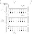
FIG. 2 is a schematic structural view of a furnace sootblower system of the present invention;
FIG. 3 is a side view of the arrangement of the furnace sootblower system of the present invention;
FIG. 4 is a top view of the arrangement of the furnace sootblower system of the present invention;
FIG. 5 is a schematic view of the opening angle of the soot blowing holes of the furnace soot blowing branch pipe according to the present invention;
in the drawings: 1. the system comprises a flue gas inlet, 2 parts of a first water-cooled settling chamber, 3 parts of a second water-cooled settling chamber, 4 parts of a third water-cooled settling chamber, 5 parts of a first full water-cooled ash bucket, 6 parts of a second full water-cooled ash bucket, 7 parts of a high-temperature expansion joint, 8 parts of a high-efficiency cyclone separator, 9 parts of a turning flue, 10 parts of a tail vertical steel flue, 11 parts of a superheater, 12 parts of an evaporator, 13 parts of an economizer, 14 parts of a pulse shock wave ash blower, 15 parts of a flue gas outlet, 16 parts of a boiler barrel, 17 parts of a first water-cooled packing auger, 18 parts of a second water-cooled packing auger, 19 parts of a collision type inertial separator, 20 parts of a main water supply pipeline, 21 parts of a water supply connecting pipe, 22 parts of a first descending pipe, 23 parts of a first ascending pipe, 24 parts of a second descending pipe, 25 parts of a second ascending pipe, 26 parts of a saturated steam connecting pipe, 27 parts of a main steam pipeline, 28 parts of a front wall water-cooled wall, 29 parts of two side wall walls, 30 parts of a front partition wall, 31 parts of a rear partition wall, 32. The furnace soot blowing system comprises a rear wall water-cooled wall, 33 furnace soot blowing pipe systems, 34 furnace soot blowing main pipes, 35 furnace soot blowing branch pipes and 36 fixed supports.
Detailed Description
The technical solution of the present invention is further explained below with reference to the accompanying drawings.
Fig. 1 is a schematic structural diagram of a cement kiln bypass air-bleeding waste heat boiler of the invention, which comprises: a flue gas inlet 1, a first water-cooled settling chamber 2, a second water-cooled settling chamber 3, a third water-cooled settling chamber 4, a first full water-cooled ash bucket 5, a second full water-cooled ash bucket 6, a high-temperature expansion joint 7, a high-efficiency cyclone separator 8, a turning flue 9, a tail vertical steel flue 10, a superheater 11, an evaporator 12, an economizer 13, a pulse shock wave soot blower 14, a flue gas outlet 15, a boiler barrel 16, a first water-cooled auger 17, a second water-cooled auger 18, a main water supply pipeline 20, a water supply connecting pipe 21, a first descending pipe 22, a first ascending pipe 23, a second descending pipe 24, a second ascending pipe 25 and a saturated steam connecting pipe 26, wherein the lower part of the first water-cooled settling chamber 2 is provided with the flue gas inlet 1, the bottom of the first water-cooled settling chamber 2 is provided with the first full water-cooled ash bucket 5, the first full water-cooled ash bucket 5 is used for collecting part of high-temperature fly ash particles, the ash outlet of the first full water-cooled ash bucket 5 is provided with the first water-cooled auger 17, the first water-cooled packing auger 17 of the invention continuously operates when the boiler is used, so that the collected fly ash particles are continuously discharged. The outlet of the first water-cooling settling chamber 2 is connected with the inlet of the second water-cooling settling chamber 3, the outlet of the second water-cooling settling chamber 3 is connected with the inlet of the third water-cooling settling chamber 4, so that the first water-cooling settling chamber 2 and the second water-cooling settling chamber 3 are arranged in an inverted U shape, the second water-cooling settling chamber 3 and the third water-cooling settling chamber 4 are arranged in a U shape, on one hand, the floor area of the cement kiln bypass air-release waste heat boiler is saved, on the other hand, the first water-cooling settling chamber 2, the second water-cooling settling chamber 3 and the third water-cooling settling chamber 4 provide large high-temperature flue gas circulation cross sections, the flow speed of the control flue gas is less than or equal to 2m/s, and the settling separation efficiency of high-temperature fly ash particles is improved. The second water-cooled settling chamber 3 and the third water-cooled settling chamber 4 are both connected with a second full water-cooled ash bucket 6, the first full water-cooled ash bucket 5 and the second full water-cooled ash bucket 6 are both composed of membrane wall tube banks, and water in the tube banks absorbs heat of high-temperature flue gas and fly ash to generate saturated steam-water mixture, so that the temperature of the collected high-temperature fly ash is reduced. Saturated water in the boiler barrel 16 is respectively connected with the first water-cooling settling chamber 2, the second water-cooling settling chamber 3, the third water-cooling settling chamber 4, the first full water-cooling ash bucket 5 and the second full water-cooling ash bucket 6 through the first descending pipe 22, so that the saturated water enters the first water-cooling settling chamber 2, the second water-cooling settling chamber 3, the third water-cooling settling chamber 4, the first full water-cooling ash bucket 5 and the second full water-cooling ash bucket 6, and a saturated steam-water mixture is introduced into the boiler barrel 16 for separation and then is overheated by the superheater 11. The step distribution of a flue gas temperature field is realized through a first water-cooled settling chamber 2, a second water-cooled settling chamber 3, a third water-cooled settling chamber 4, a first full water-cooled ash bucket 5 and a second full water-cooled ash bucket 6, the flue gas temperature is reduced to 650 ℃ through the first water-cooled settling chamber 3 and the second water-cooled settling chamber 4, and when the temperature is higher than the condensation temperature of alkali metal volatile matters, part of high-temperature fly ash particles are settled, separated and collected; the temperature of the flue gas is reduced to 500 ℃ after radiation heat exchange in the third water-cooled settling chamber 3, which is beneficial to arranging a high-efficiency cyclone separator 8 behind the third water-cooled settling chamber 3. Saturated steam-water mixtures generated in the first water-cooled settling chamber 2, the second water-cooled settling chamber 3 and the third water-cooled settling chamber 4 enter the drum 16 through the first ascending pipe 23, so that the generated saturated steam-water mixtures naturally circulate to enter the drum 16; the ash outlet of the second full water-cooling ash bucket 6 is provided with a second water-cooling auger 18, the second water-cooling auger 18 in the invention continuously runs when the boiler is used, the fly ash particles in the water-cooling ash bucket are continuously discharged in a mechanical stirring ash discharge mode, and simultaneously, the feed water is adopted to cool the high-temperature fly ash particles, thereby improving the boiler efficiency; and a collision type inertia separator 19 is arranged in the second full water-cooled ash bucket 6 and is used for further improving the self-cleaning ash separation efficiency of the waste heat boiler for fly ash particles in high-temperature flue gas. The inlets of the first water-cooling packing auger 17 and the second water-cooling packing auger 18 are both connected with the main water supply pipeline 20, the high-temperature fly ash particles in the first water-cooling packing auger 17 and the second water-cooling packing auger 18 are cooled through boiler feed water in the main water supply pipeline 20, and the outlets of the first water-cooling packing auger 17 and the second water-cooling packing auger 18 are connected with the inlet of the economizer 13, so that the boiler feed water for cooling the high-temperature fly ash particles flows into the economizer 13. The outlet of the third water-cooled settling chamber 4 is connected with the inlet of the high-efficiency cyclone separator 8 through the high-temperature expansion joint 7, and the high-temperature expansion joint 7 and the high-efficiency cyclone separator 8 are connected in a way of inclining by 0-30 degrees in the right-lower direction in the vertical direction, so that the separation efficiency of the high-efficiency cyclone separator 8 can be improved; the outlet of the high-efficiency cyclone separator 8 is connected with the inlet of the diversion flue 9, and the separated medium-temperature fly ash particles are discharged out of the furnace from the lower part of the high-efficiency cyclone separator 8. The outlet of the turning flue 9 is connected with the inlet of the tail vertical steel flue 10, the outlet of the tail vertical steel flue 10 is connected with the flue gas outlet 15, the superheater 11, the evaporator 12 and the economizer 13 are sequentially arranged in the tail vertical steel flue 10 from top to bottom, and pulse shock wave soot blowers 14 are uniformly arranged on each layer of convection heating surface tube bundle of the superheater 11, the evaporator 12 and the economizer 13, so that the accumulated dust on the outer wall of the convection heating surface tube is periodically removed, the heat exchange efficiency of the heating surface tube is improved, and the long-period stable operation of the boiler is realized; the outlet of the economizer 13 is connected with the drum 16 through a feed water connecting pipe 21, feed water enters the drum 16 after being heated by absorbing low-quality flue gas heat through the economizer 13, so that the heat absorption of the feed water in an evaporation heating surface can be reduced, and the heat efficiency of the waste heat boiler is improved. The drum 16 is connected with the water inlets of the first water-cooled settling chamber 2, the second water-cooled settling chamber 3, the third water-cooled settling chamber 4, the first full water-cooled ash bucket 5 and the second full water-cooled ash bucket 6 through a first descending pipe 22, generates a saturated steam-water mixture through heat exchange, returns to the drum 16 through a first ascending pipe 23, and returns saturated steam in the saturated steam-water mixture to the drum 16; the drum 16 is connected with the water inlet of the evaporator 12 through a second downcomer 24, and the outlet of the evaporator 12 is connected with the drum 16 through a second riser 25, so as to form a complete natural circulation loop. The saturated steam in the drum 16 is connected to the inlet of the superheater 11 through a saturated steam connection pipe 26, and superheated steam heated to a rated temperature and pressure by the saturated steam is sent to the steam turbine through a main steam pipe 27.
In the invention, the connection modes of the first water-cooled settling chamber 2, the second water-cooled settling chamber 3, the third water-cooled settling chamber 4, the first full water-cooled ash bucket 5, the second full water-cooled ash bucket 6, the superheater 11, the evaporator 12, the economizer 13, the drum 16, the first water-cooled packing auger 17, the second water-cooled packing auger 18 and other parts are connected by a steam-water connection pipeline system if not particularly described.
The first water-cooled settling chamber 2, the second water-cooled settling chamber 3 and the third water-cooled settling chamber 4 are used as a radiation heating surface to generate a saturated steam-water mixture and simultaneously reduce the temperature of high-temperature dust-containing flue gas, along with the reduction of the temperature of the flue gas, the flow velocity of the flue gas is gradually reduced on one hand, and the settling and capturing of fly ash particles in the flue gas are realized by combining a steering structure at the joint of each water-cooled settling chamber, and on the other hand, alkali metal compounds and the like in the gaseous state due to high temperature are separated out and solidified along with the temperature reduction, so that conditions are created for capturing the fly ash particles by the high-efficiency cyclone separator 8.
The first water-cooling settling chamber 2, the second water-cooling settling chamber 3 and the third water-cooling settling chamber 4 are all arranged by adopting water-cooling film wall hollow flues, and long-term operation under high fly ash concentration is guaranteed. The first water-cooled settling chamber 2 consists of a front wall water-cooled wall 28, two side wall water-cooled walls 29 and a front partition wall water-cooled wall 30; the second water-cooled settling chamber 3 consists of a front partition wall water-cooled wall 30, two side wall water-cooled walls 29 and a rear partition wall water-cooled wall 31; the third water-cooled settling chamber 4 consists of a rear partition wall water-cooled wall 31, two side wall water-cooled walls 29 and a rear wall water-cooled wall 32. The front wall water-cooled wall 28, the two side wall water-cooled walls 29, the front partition wall water-cooled wall 30, the rear partition wall water-cooled wall 31 and the rear wall water-cooled wall 32 in the invention are all composed of a lower header, a membrane wall and an upper header.
Referring to fig. 2-5, in the present invention, a group of furnace soot blower systems 33 are disposed in the first water-cooled settling chamber 2 for timely purging the fly ash particles adhered to the inner wall of the first water-cooled settling chamber 2. The furnace sootblower system 33 of the present invention comprises: the hearth soot blowing device comprises a hearth soot blowing main pipe 34, hearth soot blowing branch pipes 35 and a fixing support 36, wherein a plurality of hearth soot blowing branch pipes 35 are arranged on the hearth soot blowing main pipe 34, soot blowing holes of two adjacent rows of the hearth soot blowing branch pipes 35 are arranged in a crossed mode, the hearth soot blowing main pipe 34 is fixedly connected with a first water-cooling settling chamber 2 through the fixing support 36, and the hearth soot blowing main pipe 34 and the hearth soot blowing branch pipes 35 can be made of high-temperature corrosion resistant materials. And a plurality of gas source inlets are arranged on the side wall of the first water-cooled settling chamber 2, and saturated steam or compressed air sweeps bonded fly ash particles towards the inner wall of the first water-cooled settling chamber 2 through the soot blowing holes of the hearth soot blowing branch pipes 35. Two soot blowing angles are arranged on one soot blowing hole of the hearth soot blowing branch pipe 35, wherein the two soot blowing angles are respectively 15-20 degrees and 30-40 degrees, so that the condition that a soot blowing medium vertically acts on the outer wall of the water wall pipe to cause local thinning of the pipe wall can be avoided, the blowing range is expanded, and the blowing effect is obviously improved.
The working principle and the process of the cement kiln bypass air-bleeding waste heat boiler are as follows:
the flue gas flow is as follows: dust-containing flue gas at 950-500 ℃ in a cement process production line enters a first water-cooled settling chamber 2 through a flue gas inlet 1, and fly ash particles separated by settling are cooled and collected through a first full water-cooled ash bucket 5 and then are continuously discharged out of the furnace through a first water-cooled auger 17; then, the flue gas is deposited and separated in a second water-cooled settling chamber 3, a third water-cooled settling chamber 4, a second full water-cooled ash bucket 6 and an impact type inertial separator 19, and part of fly ash particles below 500 ℃ are continuously discharged out of the furnace through a second water-cooled auger 18; then, the flue gas enters a high-efficiency cyclone separator 8 through a high-temperature expansion joint 7, fly ash particles below 500 ℃ are further finely separated, and the fly ash particles are discharged out of the furnace through an ash outlet at the lower part of the high-efficiency cyclone separator 8; the flue gas enters a tail vertical steel flue 10 through a turning flue 9, and exchanges heat with a convection heating surface such as a superheater 11, an evaporator 12, an economizer 13 and the like in sequence, meanwhile, a pulse shock wave soot blower 14 performs soot cleaning, and collected fly ash particles are discharged out of the furnace through a lower ash hopper of a flue gas outlet 15.
The steam-water flow is as follows: the water supply of the waste heat boiler enters a first water-cooling auger 17 and a second water-cooling auger 18 respectively through a main water supply pipeline 20 to cool high-temperature fly ash particles, then the high-temperature fly ash particles are connected into an economizer 13, and the high-temperature fly ash particles are heated to hot water with certain pressure and temperature in the economizer 13 and then enter a boiler barrel 16 through a water supply connecting pipe 21; saturated water in the boiler barrel 16 respectively enters a first water-cooling settling chamber 2, a second water-cooling settling chamber 3, a third water-cooling settling chamber 4, a first full water-cooling ash bucket 5 and a second full water-cooling ash bucket 6 through a first descending pipe 22, enters the evaporator 12 through a second descending pipe 24, and is heated in the water-cooling settling chamber, the water-cooling ash bucket and the evaporator to generate a saturated steam-water mixture, and the saturated steam-water mixture returns to the boiler barrel 16 through a first ascending pipe 23 and a second ascending pipe 24; the saturated steam separated from the drum 16 enters the superheater 11 through a saturated steam outlet pipe 26 for heat convection, and superheated steam reaching a rated temperature and pressure is generated and sent to a steam turbine through a main steam pipeline 27.
The cement kiln bypass air discharge waste heat boiler disclosed by the invention adopts the three-flue water-cooled settling chamber to realize the separation and collection of high-temperature fly ash particles in a flue gas temperature range of 950-500 ℃, so that the content of the fly ash particles in high-temperature flue gas is reduced, the miniaturization of the subsequent arrangement of the high-efficiency cyclone separator 8 is facilitated, and the risk of fly ash adhesion and blockage in the high-efficiency cyclone separator 8 is reduced; the separation of the intermediate temperature fly ash particles is realized by adopting the high-efficiency cyclone separator in the temperature range of the flue gas below 500 ℃, the content of the fly ash particles in the intermediate temperature flue gas is greatly reduced, the subsequent heat exchange of a convection heating surface in a vertical flue is facilitated, and the problems of pipe explosion and other operation accidents caused by fly ash adhesion and blockage of a convection heating surface pipe are solved.
The above is only a preferred embodiment of the present invention, and the scope of the present invention is not limited to the above embodiment, and any technical solutions that fall under the spirit of the present invention fall within the scope of the present invention. It should be noted that modifications and embellishments within the scope of the invention may be made by those skilled in the art without departing from the principle of the invention.
Claims (10)
1. The utility model provides a cement kiln bypass air bleed exhaust heat boiler which characterized in that includes: a flue gas inlet (1), a first water-cooling settling chamber (2), a second water-cooling settling chamber (3), a third water-cooling settling chamber (4), a first full water-cooling ash bucket (5), a second full water-cooling ash bucket (6), a high-temperature expansion joint (7), a high-efficiency cyclone separator (8), a steering flue (9), a tail vertical steel flue (10), a superheater (11), an evaporator (12), an economizer (13), a pulse shock wave ash blower (14), a flue gas outlet (15), a boiler barrel (16), a first water-cooling auger (17), a second water-cooling auger (18), a main water supply pipeline (20), a water supply connecting pipe (21), a first descending pipe (22), a first ascending pipe (23), a second descending pipe (24), a second ascending pipe (25) and a saturated steam connecting pipe (26), wherein the flue gas inlet (1) is arranged at the lower part of the first water-cooling settling chamber (2), the bottom of first water-cooling deposit room (2) is equipped with first full water-cooling ash bucket (5), the ash hole of first full water-cooling ash bucket (5) is equipped with first water-cooling auger (17), the export of first water-cooling deposit room (2) and the entry linkage of second water-cooling deposit room (3), the export of second water-cooling deposit room (3) and the entry linkage of third water-cooling deposit room (4), second water-cooling deposit room (3) and third water-cooling deposit room (4) all are connected with second full water-cooling ash bucket (6), saturated water in boiler barrel (16) is connected with first water-cooling deposit room (2), second water-cooling deposit room (3), third water-cooling deposit room (4), first full water-cooling ash bucket (5), second full water-cooling ash bucket (6) respectively through first downtake (22), first water-cooling deposit room (2), second water-cooling deposit room (3), Saturated vapor water in the third water-cooling settling chamber (4) is connected with a boiler barrel (16) through a first ascending pipe (23), an ash outlet of a second full water-cooling ash bucket (6) is provided with a second water-cooling packing auger (18), inlets of the first water-cooling packing auger (17) and the second water-cooling packing auger (18) are connected with a main water supply pipeline (20), outlets of the first water-cooling packing auger (17) and the second water-cooling packing auger (18) are connected with an inlet of an economizer (13) through the main water supply pipeline (20), an outlet of the third water-cooling settling chamber (4) is connected with an inlet of a high-efficiency cyclone separator (8) through a high-temperature expansion joint (7), an outlet of the high-efficiency cyclone separator (8) is connected with an inlet of a steering flue (9), an outlet of the steering flue (9) is connected with an inlet of a tail vertical steel flue (10), an outlet of the tail vertical steel flue (10) is connected with a flue gas outlet (15), the superheater (11), the evaporator (12) and the economizer (13) are sequentially arranged in the tail vertical steel flue (10) from top to bottom, and pulse shock wave soot blowers (14) are uniformly arranged on each layer of convection heating surface tube bundle of the superheater (11), the evaporator (12) and the economizer (13); the outlet of the economizer (13) is connected with the boiler barrel (16) through a water supply connecting pipe (21); the boiler barrel (16) is connected with water inlets of the first water-cooling settling chamber (2), the second water-cooling settling chamber (3), the third water-cooling settling chamber (4), the first full water-cooling ash bucket (5) and the second full water-cooling ash bucket (6) through a first descending pipe (22) and returns to the boiler barrel (16) through a first ascending pipe (23); the boiler barrel (16) is connected with a water inlet of the evaporator (12) through a second descending pipe (24), and an outlet of the evaporator (12) is connected with the boiler barrel (16) through a second ascending pipe (25); the saturated steam in the drum (16) is connected with the inlet of the superheater (11) through a saturated steam connecting pipe (26).
2. The cement kiln bypass air-bleeding waste heat boiler according to claim 1, characterized in that the first water-cooled settling chamber (2) is arranged by adopting a water-cooled membrane wall hollow flue, and consists of a front wall water-cooled wall (28), two side wall water-cooled walls (29) and a front partition wall water-cooled wall (30).
3. The cement kiln bypass air-bleeding waste heat boiler according to claim 1, characterized in that the second water-cooled settling chamber (3) is arranged by adopting a water-cooled membrane wall hollow flue, and consists of a front partition wall water-cooled wall (30), two side wall water-cooled walls (29) and a rear partition wall water-cooled wall (31).
4. The cement kiln bypass air-bleeding waste heat boiler according to claim 1, characterized in that the third water-cooled settling chamber (4) is arranged by adopting a water-cooled membrane wall hollow flue, and consists of a rear partition wall water-cooled wall (31), two side wall water-cooled walls (29) and a rear wall water-cooled wall (32).
5. The cement kiln bypass air-release waste heat boiler according to claim 1, characterized in that the first water-cooled settling chamber (2) and the second water-cooled settling chamber (3) are arranged in an inverted U shape, and the second water-cooled settling chamber (3) and the third water-cooled settling chamber (3) are arranged in a U shape.
6. The cement kiln bypass air-bleeding waste heat boiler according to claim 1, characterized in that an impact type inertia separator (19) is arranged in the second full water-cooled ash bucket (6).
7. The cement kiln bypass air-bleeding waste heat boiler according to claim 1, characterized in that the high temperature expansion joint (7) and the high efficiency cyclone separator (8) are connected in a manner of inclining 0-30 degrees to the right and downwards in the vertical direction.
8. The cement kiln bypass air-bleeding waste heat boiler according to claim 1, characterized in that a group of hearth soot-blowing pipe systems (33) are arranged in the first water-cooled settling chamber (2).
9. The cement kiln bypass air discharge waste heat boiler according to claim 1, wherein the furnace soot blowing pipe system (33) comprises: the hearth soot blowing device comprises a hearth soot blowing main pipe (34), hearth soot blowing branch pipes (35) and a fixing support (36), wherein a plurality of hearth soot blowing branch pipes (35) are arranged on the hearth soot blowing main pipe (34), soot blowing holes of two adjacent upper and lower rows of hearth soot blowing branch pipes (35) are arranged in a crossed mode, and the hearth soot blowing main pipe (34) is fixedly connected with a first water-cooling settling chamber (2) through the fixing support (36).
10. The cement kiln bypass air-bleeding waste heat boiler as claimed in claim 9, characterized in that one soot-blowing hole of the furnace soot-blowing branch pipe (35) has two soot-blowing angles, respectively 15-20 ° and 30-40 °.
Priority Applications (1)
| Application Number | Priority Date | Filing Date | Title |
|---|---|---|---|
| CN202111538688.5A CN114184055A (en) | 2021-12-16 | 2021-12-16 | Cement kiln bypass air discharge waste heat boiler |
Applications Claiming Priority (1)
| Application Number | Priority Date | Filing Date | Title |
|---|---|---|---|
| CN202111538688.5A CN114184055A (en) | 2021-12-16 | 2021-12-16 | Cement kiln bypass air discharge waste heat boiler |
Publications (1)
| Publication Number | Publication Date |
|---|---|
| CN114184055A true CN114184055A (en) | 2022-03-15 |
Family
ID=80544036
Family Applications (1)
| Application Number | Title | Priority Date | Filing Date |
|---|---|---|---|
| CN202111538688.5A Pending CN114184055A (en) | 2021-12-16 | 2021-12-16 | Cement kiln bypass air discharge waste heat boiler |
Country Status (1)
| Country | Link |
|---|---|
| CN (1) | CN114184055A (en) |
Cited By (1)
| Publication number | Priority date | Publication date | Assignee | Title |
|---|---|---|---|---|
| CN114777505A (en) * | 2022-04-15 | 2022-07-22 | 湖南长宏锅炉科技股份有限公司 | Three-chamber rare earth recovery waste heat furnace |
Citations (9)
| Publication number | Priority date | Publication date | Assignee | Title |
|---|---|---|---|---|
| CN202012897U (en) * | 2011-01-24 | 2011-10-19 | 大连易世达新能源发展股份有限公司 | Cement kiln tail bypass wind discharging exhaust-heat boiler |
| CN102748742A (en) * | 2012-07-31 | 2012-10-24 | 太原锅炉集团有限公司 | Vertical single-drum refuse-incinerating waste heat boiler |
| CN202747313U (en) * | 2012-07-31 | 2013-02-20 | 山东华源锅炉有限公司 | Waste heat boiler for comprehensive utilization of industrial waste in aluminum factory |
| CN203656886U (en) * | 2013-11-29 | 2014-06-18 | 郑州锅炉股份有限公司 | Rotary cement kiln tail bypass exhaust air waste heat boiler |
| CN204460149U (en) * | 2015-01-12 | 2015-07-08 | 杭州伯勒计算机技术有限公司 | A kind of all-oxygen combustion glass furnace high-temperature residual heat boiler |
| CN106287631A (en) * | 2016-09-30 | 2017-01-04 | 四川东华锅炉工程技术有限公司 | Energy-saving dedusting horizontal revolving kiln waste heat boiler |
| CN205878107U (en) * | 2016-03-07 | 2017-01-11 | 自贡东方热电配套有限公司 | Waste incineration exhaust -heat boiler |
| CN208720185U (en) * | 2018-07-19 | 2019-04-09 | 南通万达锅炉有限公司 | A kind of cement kiln tertiary air joint overheat waste heat boiler |
| CN211119279U (en) * | 2019-08-14 | 2020-07-28 | 江苏东九重工股份有限公司 | Cement kiln handles solid waste bypass exhaust-heat boiler in coordination |
-
2021
- 2021-12-16 CN CN202111538688.5A patent/CN114184055A/en active Pending
Patent Citations (9)
| Publication number | Priority date | Publication date | Assignee | Title |
|---|---|---|---|---|
| CN202012897U (en) * | 2011-01-24 | 2011-10-19 | 大连易世达新能源发展股份有限公司 | Cement kiln tail bypass wind discharging exhaust-heat boiler |
| CN102748742A (en) * | 2012-07-31 | 2012-10-24 | 太原锅炉集团有限公司 | Vertical single-drum refuse-incinerating waste heat boiler |
| CN202747313U (en) * | 2012-07-31 | 2013-02-20 | 山东华源锅炉有限公司 | Waste heat boiler for comprehensive utilization of industrial waste in aluminum factory |
| CN203656886U (en) * | 2013-11-29 | 2014-06-18 | 郑州锅炉股份有限公司 | Rotary cement kiln tail bypass exhaust air waste heat boiler |
| CN204460149U (en) * | 2015-01-12 | 2015-07-08 | 杭州伯勒计算机技术有限公司 | A kind of all-oxygen combustion glass furnace high-temperature residual heat boiler |
| CN205878107U (en) * | 2016-03-07 | 2017-01-11 | 自贡东方热电配套有限公司 | Waste incineration exhaust -heat boiler |
| CN106287631A (en) * | 2016-09-30 | 2017-01-04 | 四川东华锅炉工程技术有限公司 | Energy-saving dedusting horizontal revolving kiln waste heat boiler |
| CN208720185U (en) * | 2018-07-19 | 2019-04-09 | 南通万达锅炉有限公司 | A kind of cement kiln tertiary air joint overheat waste heat boiler |
| CN211119279U (en) * | 2019-08-14 | 2020-07-28 | 江苏东九重工股份有限公司 | Cement kiln handles solid waste bypass exhaust-heat boiler in coordination |
Cited By (1)
| Publication number | Priority date | Publication date | Assignee | Title |
|---|---|---|---|---|
| CN114777505A (en) * | 2022-04-15 | 2022-07-22 | 湖南长宏锅炉科技股份有限公司 | Three-chamber rare earth recovery waste heat furnace |
Similar Documents
| Publication | Publication Date | Title |
|---|---|---|
| WO2015124007A1 (en) | Fluidized bed boiler with integration of multifunctional inertial gravity separators and multiple types of furnaces | |
| WO2021109324A1 (en) | Modularized natural convection boiler system for recovering waste heat of liquid slag | |
| CN102425787A (en) | Liquid slag trapping biomass combustion device and method | |
| CN101724728A (en) | Waste heat recovery and bag-type dust removal system | |
| CN204986938U (en) | Energy -conserving dust removal troilite exhaust -heat boiler | |
| CN101979951B (en) | Dry dedusting and sensible heat recovery system for electric furnace flue gas | |
| CN114184055A (en) | Cement kiln bypass air discharge waste heat boiler | |
| CN101893385A (en) | Device for power generation from waste heat of metallic silicon smelting electric furnace and process flow thereof | |
| CN111578723A (en) | Metallurgical high temperature dust-containing waste gas treatment system | |
| CN201811226U (en) | Gas and air device of condensation type circulating fluidized-bed boiler | |
| CN215982491U (en) | Pipe frame type waste heat recovery boiler matched with garbage pyrolysis incineration system | |
| CN206112887U (en) | Energy -conserving horizontal rotary kiln waste heat boiler that removes dust | |
| CN115950266A (en) | Vertical exhaust-heat boiler is arranged to dislocation segmentation to hot stove flue gas in ore deposit | |
| CN201688717U (en) | Afterheat generating device of metallic silicon electric melting furnace | |
| CN112283681A (en) | Angle tube boiler with tail quenching heating surface | |
| CN101893388A (en) | Electric furnace double dust collection and waste heat recovery system and method | |
| CN101713542B (en) | Refuse incinerator of circulating fluid bed for burning out ash by radiation | |
| CN212132406U (en) | Pulverized coal fired boiler capable of preventing convection heating surface from being contaminated and slagging | |
| CN106195968A (en) | Flue gas processing device and rotary hearth furnace high-temperature high dust smoke processing system | |
| CN211853961U (en) | Bagasse boiler | |
| CN106287631A (en) | Energy-saving dedusting horizontal revolving kiln waste heat boiler | |
| CN213930861U (en) | Angle tube boiler with tail quenching heating surface | |
| CN212566916U (en) | Metallurgical high temperature dust-containing waste gas treatment system | |
| CN207230501U (en) | A kind of waste heat boiler | |
| CN205535709U (en) | Flue waste heat utilization system |
Legal Events
| Date | Code | Title | Description |
|---|---|---|---|
| PB01 | Publication | ||
| PB01 | Publication | ||
| SE01 | Entry into force of request for substantive examination | ||
| SE01 | Entry into force of request for substantive examination | ||
| RJ01 | Rejection of invention patent application after publication |
Application publication date: 20220315 |
|
| RJ01 | Rejection of invention patent application after publication |