CN114164772A - Rhombic hanging basket for viaduct cantilever pouring construction and mounting method - Google Patents
Rhombic hanging basket for viaduct cantilever pouring construction and mounting method Download PDFInfo
- Publication number
- CN114164772A CN114164772A CN202111486911.6A CN202111486911A CN114164772A CN 114164772 A CN114164772 A CN 114164772A CN 202111486911 A CN202111486911 A CN 202111486911A CN 114164772 A CN114164772 A CN 114164772A
- Authority
- CN
- China
- Prior art keywords
- basket
- box girder
- truss
- sliding block
- slide rail
- Prior art date
- Legal status (The legal status is an assumption and is not a legal conclusion. Google has not performed a legal analysis and makes no representation as to the accuracy of the status listed.)
- Pending
Links
Images


Classifications
-
- E—FIXED CONSTRUCTIONS
- E01—CONSTRUCTION OF ROADS, RAILWAYS, OR BRIDGES
- E01D—CONSTRUCTION OF BRIDGES, ELEVATED ROADWAYS OR VIADUCTS; ASSEMBLY OF BRIDGES
- E01D21/00—Methods or apparatus specially adapted for erecting or assembling bridges
- E01D21/10—Cantilevered erection
Abstract
The invention discloses a rhombic hanging basket for pouring of a cantilever of a viaduct and an installation method, and belongs to the field of hanging baskets for viaducts. The utility model provides a basket is hung with rhombus to overpass cantilever pouring construction, includes: the hanging basket traveling system comprises sliding rails, sliding rail anchor rods, steel sleepers and limiting assemblies, wherein the steel sleepers are laid on the top of the box girder at equal intervals, three transverse sliding rails are arranged on the steel sleepers, each sliding rail is fixed on the top of the box girder through the sliding rail anchor rods, and the limiting assemblies are mounted at the left ends of the sliding rails; the main truss, the main truss is equipped with threely, and the bottom sliding connection of main truss is at the left end of slide rail, and the middle part of three main truss is connected through well portal, and the box girder was kept away from to one side top of three main truss is connected through the entablature. This basket is hung with rhombus to overpass cantilever construction, the extension slide rail is convenient, and demolising of follow-up slide rail is convenient, and to hanging the promotion of basket convenient stable, the main truss can not break away from the slide rail, can improve the building efficiency of overpass.
Description
Technical Field
The invention relates to the technical field of hanging baskets for viaducts, in particular to a rhombic hanging basket for cantilever pouring construction of a viaduct and an installation method.
Background
The rhombic hanging basket is widely applied to the segmented suspension casting construction of a large-span continuous beam bridge and a continuous steel bridge, mainly comprises a bearing system, a traveling system, a suspension system and an anchoring device, and is used for hanging a hanging basket template by using the hanging basket for casting the bridge when the bridge is constructed;
hang the basket kind among the prior art and have a lot of varieties, wherein the rhombus is hung the basket and is more common, utilize the rhombus support frame of bridge both sides to prop up the front beam, use suspension system fixed end basket, a mold for the installation, help is pour, the basket is hung to current rhombus need to hang the basket and move forward after having pour one end case roof beam of being under construction, then generally can connect new track forward before the removal and connect original track, current welding track process is inefficient, it is troublesome subsequently demolishs, and because it is heavier to hang the basket, be difficult to promote forward.
Disclosure of Invention
The invention aims to solve the problems that in the prior art, when in actual use, a track is lengthened by welding, the efficiency is low, the follow-up dismantling is troublesome, and a hanging basket is heavy and is not easy to push forwards, and provides a rhombic hanging basket for pouring construction of a viaduct cantilever and an installation method.
In order to achieve the purpose, the invention adopts the following technical scheme:
the utility model provides a basket is hung with rhombus to overpass cantilever pouring construction, includes:
the hanging basket traveling system comprises sliding rails, sliding rail anchor rods, steel sleepers and limiting assemblies, wherein the steel sleepers are laid on the top of the box girder at equal intervals, three transverse sliding rails are arranged on the steel sleepers, each sliding rail is fixed on the top of the box girder through the sliding rail anchor rods, and the limiting assemblies are mounted at the left ends of the sliding rails;
the three main trusses are arranged, the bottoms of the main trusses are connected to the left end of the sliding rail in a sliding mode, the middle parts of the three main trusses are connected through a middle door frame, and the tops of the three main trusses, far away from the box girder, on one side are connected through an upper cross beam;
the bottom basket is arranged at the bottom of the left end of the box girder, a bottom die is arranged on the bottom basket, and the bottom die is in contact with the bottom of the left end of the box girder;
the suspension system is arranged on the bottom basket;
and the walking assisting system is arranged at the top of the box girder and is connected with the main truss.
The slide rail can make the main truss can transversely move along the case roof beam, make the main truss remove more steadily, can set up the slide rail bed hedgehopping through the steel sleeper, can fix the slide rail on the steel sleeper through the slide rail stock, make the slide rail completely fixed, can not remove, avoid the main truss to take place to rock when transversely moving about, the main truss props up the front side of the horizontal case roof beam of entablature, it is fixed to the entablature, conveniently install suspension system with the entablature simultaneously, thereby hang the end basket, thereby conveniently install die block and side form on the end basket, suspension system can be connected on the one hand to well portal, on the other hand also can link into an organic whole the main truss, keep the wholeness, walking helping hand system can promote the main truss to move about along the slide rail.
Preferably, spacing subassembly includes limiting plate, floor, inserted bar and installation round pin, the through-hole has been seted up to the left end of slide rail, and the left end side of slide rail is equipped with the side opening, the limiting plate is connected to the one end of inserted bar, and the side of limiting plate passes through the floor and connects the inserted bar, the inserted bar inserts in the through-hole, and the installation round pin that the inserted bar alternates in through the pinhole is fixed in the through-hole.
Limiting plates and inserted bars can be strengthened through the rib plates, the inserted bars can be fixed in through holes in the end portions of the sliding rails through the mounting pins, the end portions of the sliding rails can be limited through the limiting plates, and the main truss is prevented from falling off from the end portions of the sliding rails.
Preferably, hang basket traveling system and still include fixed pin, extension rail, connecting rod and pinhole, be equipped with logical groove in the extension rail, logical inslot is equipped with the connecting rod, the side equidistance of connecting rod has seted up the round hole, and the both ends of extension rail are equipped with the fixed pin in the jack respectively.
Can connect the tip at the slide rail with the extension rail through the connecting rod, then can fix the one end of connecting rod in the inside of extension rail through pinhole and fixed pin, the other end of connecting rod is fixed at the slide rail tip, then spacing subassembly is fixed in the one end that the slide rail was kept away from to the extension rail to can prolong the slide rail, need not welded mode extension slide rail, convenient quick arrangement slide rail, and convenient subsequent demolishs convenient to use.
Preferably, the main truss comprises a diamond truss, a rear anchor block, a front sliding block and a rear sliding block, the left end of the bottom of the diamond truss is connected with the front sliding block, the right end of the bottom of the diamond truss is connected with the rear sliding block, the front sliding block and the rear sliding block are respectively in sliding connection with corresponding sliding rails, and fastening bolts are respectively arranged on the front sliding block and the rear sliding block.
The left side of rhombus truss can extend to the upper left side of case roof beam to conveniently fix the end basket of downside, can make rhombus truss move about on the slide rail through preceding slider and back slider, then can twist tightly fixedly through fastening bolt, thereby the position of fixed rhombus truss.
The rhombus truss includes preceding down tube, center pillar, the pole of adding in the middle of down, goes up to add in the middle of the pole, back down tube, preceding joint block, goes up joint block, mount pad, lower joint block and back slider, the left end of the pole of adding in the middle of down is connected down and is connect back anchor block and right-hand member, and the bottom of center pillar is connected at the top of lower joint block, connect in the top of center pillar and connect the joint block, go up the left side of joint block and connect the right-hand member of adding in the middle of the pole, go up the left end of adding in the middle of the pole and connect preceding joint block, the upper end of preceding down tube is connected to the downside of preceding joint block, the lower extreme of preceding down tube connects the block, go up the right side of connecting the block and connect the upper end of back down tube, the lower extreme of back down tube connects the back anchor block, the bottom of back anchor block is connected the back slider, the back anchor block passes through the back anchor rod and fixes on the case roof beam.
A rhombic frame is formed by the front inclined rod, the vertical column, the lower inserted rod, the upper inserted rod and the rear inclined rod, so that the stability of the whole structure is ensured, and the rear anchor block is fixed by the rear anchor rod, so that the upper side of the left end of the rhombic truss is prevented from being stressed and falling.
Preferably, the main truss comprises a rear anchor rod, and the right end of the diamond truss is fixed on the box girder through the rear anchor rod. The right end of the diamond-shaped truss can be fixed through the rear anchor rod, and the phenomenon that the left end of the diamond-shaped truss is stressed too much and falls is avoided.
Preferably, the suspension system comprises a box girder suspension steel column, a middle portal frame suspension steel column and a beam suspension steel column, the front side and the rear side of the left end of the box girder are respectively connected with the right end of the bottom basket through the box girder suspension steel column, the front end and the rear end of the middle portal frame are respectively connected with the front side and the rear side of the right end of the bottom basket through the middle portal frame suspension steel column, and the upper beam is connected with the left end of the bottom basket through the beam suspension steel columns arranged at equal intervals.
Hang in midair the steel column through the case roof beam, well portal frame suspends in midair the steel column and the crossbeam suspends in midair the steel column and fixes the left and right sides of end basket, with the stable hanging in midair of end basket, avoid the position of end basket to rock.
Preferably, the suspension system further comprises a steel sling, and the front end and the rear end of the upper cross beam are respectively connected with the front side and the rear side of the left end of the bottom basket through the steel sling. The left end front side and the rear side of the bottom basket can be conveniently tensioned through the steel hanging strip, the top of the steel hanging strip is provided with the hand-operated hoist, the steel hanging strip is conveniently tensioned, and force can be applied to the left end front side and the rear side of the bottom basket.
Preferably, the walking assisting system comprises a long connecting rod, a limiting sleeve, a jack, a fixed long plate, a bottom connecting plate and a positioning anchor rod, wherein the three rear sliding blocks are connected together through the long connecting rod, the right side of the long connecting rod is connected with the left end of the jack through the limiting sleeve, the right end of the jack is connected with the fixed long plate, the bottom connecting plate is connected with the bottom of the right side of the fixed long plate, and the bottom connecting plate is fixed on the upper side of the box girder through the positioning anchor rod.
After the left end of the box girder is poured to a certain section, the fixed long plate and the bottom connection plate can be fixed through the positioning anchor rod, the jack is operated to push the long connection rod to move leftwards, the main truss is pushed to move leftwards, the mold is continuously built, and the next section of box girder is continuously poured.
Preferably, the box girder further comprises a bottom die anchor rod, and the lower side of the left end of the box girder is connected with the bottom die through the bottom die anchor rod. The bottom die can be temporarily fixed through the bottom die anchor rod, and the bottom die anchor rod and the bottom die can be sequentially detached after pouring is finished.
The mounting method of the rhombic hanging basket for the pouring construction of the viaduct cantilever comprises the following steps:
s1: firstly, leveling and drawing a line, carrying out mortar leveling at the middle position of a poured box girder, measuring and lofting, popping out a box girder central line, a track central line and a track end position line by using an ink fountain line, mutually checking the assembly direction of a main truss by using a theodolite and a vertical line, and controlling the axis position when a hanging basket travels;
s2: laying a steel sleeper along the center line of the box girder, hoisting the slide rails by using hoisting equipment, centering and placing, leveling the top surfaces of the slide rails, enabling the joints of the slide rails to be staggered by less than 3mm, enabling the error between the center line of the slide rails and the center of the box girder to be not more than 5mm, enabling the left slide rail and the right slide rail on the section of the box girder to be at the same elevation, and enabling the anchoring ribs in the anchor rods of the slide rails to be exposed out of nuts by not less than 20 mm;
s3: the diamond truss is installed to a required position through the front sliding block and the rear sliding block, then the right end of the diamond truss is fixed through the rear anchor rod, and meanwhile fastening bolts on the front sliding block and the rear sliding block are screwed tightly, so that the positions of the front sliding block and the rear sliding block on the sliding rail are fixed;
s4: respectively installing a middle portal frame and an upper cross beam on the diamond truss, then suspending and fixing the bottom basket through a suspension system, and adjusting the suspension system to enable the bottom of the bottom basket to be close to the bottom of the box girder;
s5: respectively installing a bottom die, a side die and an inner die, then installing an inner die supporting frame, fixing the inner die, and then fixing the bottom die through a bottom die anchor rod;
s6: and carrying out comprehensive inspection again after the cradle is installed, centering by using a full instrument, correcting the center line position of the cradle, leveling by using a level gauge, adjusting the elevation by using a hanging rod, and paying attention to the setting of pre-camber during the adjustment of the elevation.
Compared with the prior art, the invention provides the rhombic hanging basket for the pouring construction of the viaduct cantilever and the installation method, and the rhombic hanging basket has the following beneficial effects:
1. this overpass cantilever pouring construction hangs basket with rhombus, the slide rail can make the main truss can transversely move along the case roof beam, it is more steady to make the main truss remove, can be with the slide rail bed hedgehopping through the steel sleeper, can fix the slide rail on the steel sleeper through the slide rail stock, make the slide rail completely fixed, can not remove, avoid the main truss to take place to rock when transversely moving, the main truss props up the front side of entablature horizontal case roof beam, it is fixed to the entablature, conveniently use entablature installation suspension system simultaneously, thereby hang the end basket, thereby conveniently install die block and side form on the end basket, suspension system can be connected on the one hand to well portal, on the other hand also can link into an organic whole with the main truss, keep the wholeness, walking helping hand system can promote the main truss along the slide rail activity.
2. This overpass cantilever pouring construction hangs basket with rhombus, pour one section back of accomplishing at the left end of case roof beam, can fix fixed long slab and end fishplate bar through the location stock, through operation jack, make the jack push the extension bar and move about left to push main truss and move about left, continue to build the mould, continue to pour next section case roof beam.
3. This basket is hung with rhombus to overpass cantilever construction, the extension slide rail is convenient, and demolising of follow-up slide rail is convenient, and to hanging the promotion of basket convenient stable, the main truss can not break away from the slide rail, can improve the building efficiency of overpass.
The parts not involved in the device are the same as or can be realized by adopting the prior art, and the invention has stable structure and convenient use and can improve the construction efficiency.
Drawings
Fig. 1 is a schematic structural diagram of a rhombic hanging basket for pouring of a cantilever of a viaduct, which is provided by the invention;
fig. 2 is a schematic partial enlarged structure view of a diamond-shaped cradle for pouring of a cantilever of a viaduct in fig. 1;
fig. 3 is a schematic rear side structure view of a rhombic hanging basket for pouring of a cantilever of a viaduct provided by the invention;
fig. 4 is a schematic partial enlarged structure diagram at a position B in fig. 3 of the rhombic hanging basket for the cantilever pouring construction of the viaduct, which is provided by the invention;
fig. 5 is a schematic side structure view of a rhombic hanging basket for pouring of a cantilever of a viaduct provided by the invention;
fig. 6 is a schematic partial enlarged structure diagram at the position C in fig. 5 of the rhombic hanging basket for the cantilever pouring construction of the viaduct provided by the invention.
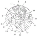
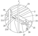
In the figure: 1 box girder, 2 hanging basket traveling systems, 21 sliding rails, 22 sliding rail anchor rods, 23 steel sleepers, 24 limiting plates, 25 ribbed plates, 26 inserted rods, 27 fixing pins, 28 extending rails, 29 connecting rods, 210 pin holes, 211 mounting pins, 3 main trusses, 31 front inclined rods, 32 vertical columns, 33 lower inclined rods, 34 upper inclined rods, 35 rear inclined rods, 36 front connecting blocks, 37 upper connecting blocks, 38 rear anchor blocks, 39 front sliding blocks, 310 mounting seats, 311 lower connecting blocks, 312 rear anchor rods, 313 rear sliding blocks, 4 middle door frames, 5 upper cross beams, 6 suspension systems, 61 box girder suspension steel columns, 62 middle door frame suspension steel columns, 63 steel hanging strips, 64 cross beam suspension steel columns, 7 bottom baskets, 8 bottom moulds, 9 traveling power-assisted systems, 91 long connecting rods, 92 limiting sleeves, 93 jacks, 94 fixing long plates, 95 bottom connecting plates, 96 positioning anchor rods and 10 anchor rod bottom moulds.
Detailed Description
The technical solutions in the embodiments of the present invention will be clearly and completely described below with reference to the drawings in the embodiments of the present invention, and it is obvious that the described embodiments are only a part of the embodiments of the present invention, and not all of the embodiments.
Example (b):
in a first embodiment, referring to fig. 1 to 6, a rhombic hanging basket for pouring of a cantilever of a viaduct includes:
the hanging basket traveling system 2 comprises sliding rails 21, sliding rail anchor rods 22, steel sleepers 23 and limiting assemblies, wherein the steel sleepers 23 are laid on the top of the box girder 1 at equal intervals, the steel sleepers 23 are provided with three transverse sliding rails 21, each sliding rail 21 is fixed on the top of the box girder 1 through the sliding rail anchor rods 22, and the limiting assemblies are mounted at the left ends of the sliding rails 21;
spacing subassembly includes limiting plate 24, floor 25, inserted bar 26 and mounting pin 211, the through-hole has been seted up to the left end of slide rail 21, and the left end side of slide rail 21 is equipped with the side opening, limiting plate 24 is connected to the one end of inserted bar 26, and the side of limiting plate 24 passes through floor 25 and connects inserted bar 26, inserted bar 26 inserts in the through-hole, and the mounting pin 211 that inserted bar 26 alternates in the pin hole is fixed in the through-hole.
The connection strength of the limiting plates 24 and the inserting rods 26 can be enhanced through the rib plates 25, the inserting rods 26 can be fixed in through holes at the end parts of the sliding rails 21 through the mounting pins 211, the end parts of the sliding rails 21 can be limited through the limiting plates 24, and the main truss 3 is prevented from falling off from the end parts of the sliding rails 21.
The number of the main trusses 3 is three, the bottoms of the main trusses 3 are connected to the left end of the sliding rail 21 in a sliding mode, the middle portions of the three main trusses 3 are connected through the middle door frame 4, and the tops of the three main trusses 3 far away from the box girder 1 are connected through the upper cross beam 5;
the middle door frame 4 comprises an upper cross rod and a lower cross rod, the two cross rods are connected through an inclined rod, and the two cross rods are fixed with the middle part of the main truss 3.
The main truss 3 comprises a diamond truss, a rear anchor block 38, a front sliding block 39 and a rear sliding block 313, the left end of the bottom of the diamond truss is connected with the front sliding block 39, the right end of the bottom of the diamond truss is connected with the rear sliding block 313, the front sliding block 39 and the rear sliding block 313 are respectively in sliding connection with the corresponding sliding rails 21, and fastening bolts are respectively arranged on the front sliding block 39 and the rear sliding block 313.
The left side of the diamond truss can extend to the upper left of the box girder 1, so that the bottom basket 7 on the lower side can be conveniently fixed, the diamond truss can move on the slide rail 21 through the front slide block 39 and the rear slide block 313, and then the diamond truss can be fastened and fixed through the fastening bolt, so that the position of the diamond truss can be fixed.
The main truss 3 comprises a rear anchor rod 312, and the right end of the diamond truss is fixed on the box girder 1 through the rear anchor rod 312. The right end of the diamond-shaped truss can be fixed through the rear anchor rods 312, and the phenomenon that the left end of the diamond-shaped truss is stressed too much and falls is avoided.
The bottom basket 7 is arranged at the bottom of the left end of the box girder 1, a bottom die 8 is arranged on the bottom basket 7, and the bottom die 8 is in contact with the bottom of the left end of the box girder 1;
a suspension system 6 mounted on the bottom basket 7; the bottom basket 7 comprises a longitudinal hanging beam and a transverse hanging beam.
The suspension system 6 comprises a box girder suspension steel column 61, a middle portal frame suspension steel column 62 and a beam suspension steel column 64, the front and rear sides of the left end of the box girder 1 are respectively connected with the right end of the bottom basket 7 through the box girder suspension steel column 61, the front and rear ends of the middle portal frame 4 are respectively connected with the front and rear sides of the right end of the bottom basket 7 through the middle portal frame suspension steel column 62, and the upper beam 5 is connected with the left end of the bottom basket 7 through the beam suspension steel columns 64 which are equidistantly arranged.
The left side and the right side of the bottom basket 7 are fixed through the box girder suspension steel column 61, the middle door frame suspension steel column 62 and the beam suspension steel column 64, the bottom basket 7 is stably suspended, and the position of the bottom basket 7 is prevented from shaking.
The suspension system 6 further comprises steel hanging strips 63, and the front end and the rear end of the upper cross beam 5 are respectively connected with the front side and the rear side of the left end of the bottom basket 7 through the steel hanging strips 63. Can conveniently strain the left end front and back side of end basket 7 through steel suspender 63, the top of steel suspender 63 sets up hand block, conveniently strains steel suspender 63, and the left end front and back side application of force to end basket 7 can be adjusted.
And the walking assisting system 9 is arranged at the top of the box girder 1, and the walking assisting system 9 is connected with the main truss 3.
The walking assisting system 9 comprises a long extension rod 91, a limiting sleeve 92, a jack 93, a fixed long plate 94, a bottom connecting plate 95 and a positioning anchor rod 96, wherein the three rear sliding blocks 313 are connected together through the long extension rod 91, the right side of the long extension rod 91 is connected with the left end of the jack 93 through the limiting sleeve 92, the right end of the jack 93 is connected with the fixed long plate 94, the bottom of the right side of the fixed long plate 94 is connected with the bottom connecting plate 95, and the bottom connecting plate 95 is fixed on the upper side of the box girder 1 through the positioning anchor rod 96.
After the left end of the box girder 1 is poured into a section, the fixed long plate 94 and the bottom connection plate 95 can be fixed through the positioning anchor rods 96, the jack 93 is operated to push the long connection rod 91 to move leftwards, so that the main truss 3 is pushed to move leftwards, the mold is continuously built, and the next section of the box girder 1 is continuously poured.
The box girder comprises a box girder body and is characterized by further comprising a bottom die anchor rod 10, and the lower side of the left end of the box girder 1 is connected with a bottom die 8 through the bottom die anchor rod 10. The bottom die 8 can be temporarily fixed through the bottom die anchor rod 10, and the bottom die anchor rod 10 and the bottom die 8 can be sequentially detached after pouring is completed.
The sliding rail 21 can enable the main truss 3 to transversely move along the box girder 1, the main truss 3 can move more stably, the sliding rail 21 can be heightened through the steel sleeper 23, the sliding rail 21 can be fixed on the steel sleeper 23 through the sliding rail anchor rod 22, the sliding rail 21 is completely fixed and cannot move, shaking of the main truss 3 during transverse movement is avoided, the main truss 3 supports the upper cross beam 5 towards the front side of the box girder 1 and fixes the upper cross beam 5, meanwhile, the suspension system 6 is conveniently installed by the upper cross beam 5, the bottom basket 7 is suspended, bottom molds and side molds are conveniently installed on the bottom basket 7, the middle door frame 4 can be connected with the suspension system 6 on one hand, the main truss 3 can also be connected into a whole on the other hand, integrity is kept, and the walking assisting system 9 can push the main truss 3 to move along the sliding rail 21.
In the second embodiment, referring to fig. 1 to 6, a rhombic hanging basket for pouring of a cantilever of a viaduct is substantially the same as the first embodiment in structure, and the difference is that:
hang basket traveling system 2 and still include fixed pin 27, extension rail 28, connecting rod 29 and pinhole 210, be equipped with logical groove in the extension rail 28, logical inslot is equipped with connecting rod 29, the round hole has been seted up to the side equidistance of connecting rod 29, and the both ends of extension rail 28 are equipped with fixed pin 27 in the jack respectively.
Can connect extension rail 28 at the tip of slide rail 21 through connecting rod 29, then can fix the one end of connecting rod 29 in the inside of extension rail 28 through pinhole 210 and fixed pin 27, the other end of connecting rod 29 is fixed at the slide rail 21 tip, then spacing subassembly is fixed in the one end that slide rail 21 was kept away from to extension rail 28 to can prolong slide rail 21, need not welded mode extension slide rail 21, convenient quick deployment slide rail 21, and convenient subsequent demolishs, convenient to use.
In a third embodiment, referring to fig. 1 to 6, a rhombic hanging basket for pouring of a cantilever of a viaduct bridge is further described in the first embodiment:
the diamond truss comprises a front oblique rod 31, a vertical column 32, a lower oblique rod 33, an upper oblique rod 34, a rear oblique rod 35, a front connecting block 36, an upper connecting block 37, a mounting seat 310, a lower connecting block 311 and a rear sliding block 313, the left end of the lower connecting rod 33 is connected with a lower connecting block 311, the right end is connected with a rear anchor block 38, the top of the lower connecting block 311 is connected with the bottom of the vertical column 32, the top of the upright post 32 is connected with an upper connecting block 37, the left side of the upper connecting block 37 is connected with the right end of the upper entering rod 34, the left end of the upper inserted rod 34 is connected with a front connecting block 36, the lower side of the front connecting block 36 is connected with the upper end of the front inclined rod 31, the lower end of the front inclined rod 31 is connected with a lower connecting block 311, the right side of the upper connecting block 37 is connected with the upper end of the rear inclined rod 35, the lower end of the rear inclined rod 35 is connected with a rear anchor block 38, the bottom of a lower connecting block 311 is connected with a front sliding block 39 through a mounting seat 310, the bottom of the rear anchor block 38 is connected with a rear sliding block 313, and the rear anchor block 38 is fixed on the box girder 1 through a rear anchor rod 312.
A rhombic frame is formed by the front inclined rod 31, the vertical column 32, the lower inserted rod 33, the upper inserted rod 34 and the rear inclined rod 35, so that the stability of the whole structure is ensured, and the rear anchor block 38 is fixed by the rear anchor rod 312, so that the upper side of the left end of the rhombic truss is prevented from being stressed and falling.
Referring to fig. 1 to 6, a method for installing a rhombic hanging basket for viaduct cantilever casting construction specifically includes the following steps:
s1: firstly, leveling and drawing a line, carrying out mortar leveling at the middle position of a poured box girder 1, measuring and lofting, popping out a box girder central line, a track central line and a track end position line by using an ink fountain line, mutually checking the assembly direction of a main truss by using a theodolite and a vertical line, and controlling the axis position when a hanging basket travels;
s2: laying a steel sleeper 23 along the center line of the box girder 1, hoisting the slide rail 21 by using hoisting equipment, centering and leveling the top surface of the slide rail 21, wherein the dislocation of the joint of the slide rail 21 is less than 3mm, the error of the distance between the center line of the slide rail 21 and the center of the box girder 1 is not more than 5mm, the left slide rail 21 and the right slide rail 21 on the section of the box girder 1 are at the same elevation, and the anchoring ribs in the slide rail anchor rods 22 are exposed out of nuts and are not less than 20 mm;
s3: the diamond truss is installed to a required position through the front sliding block 39 and the rear sliding block 313, then the right end of the diamond truss is fixed through the rear anchor rod 312, and meanwhile fastening bolts on the front sliding block 39 and the rear sliding block 313 are screwed tightly, so that the positions of the front sliding block 39 and the rear sliding block 313 on the sliding rail 21 are fixed;
s4: respectively installing a middle door frame 4 and an upper cross beam 5 on the diamond truss, then suspending and fixing a bottom basket 7 through a suspension system 6, and adjusting the suspension system 6 to enable the bottom of the bottom basket 7 to be close to the bottom of the box girder 1;
s5: respectively installing a bottom die 8, a side die and an inner die, then installing an inner die supporting frame, fixing the inner die, and then fixing the bottom die 8 through a bottom die anchor rod 10;
s6: and carrying out comprehensive inspection again after the cradle is installed, centering by using a full instrument, correcting the center line position of the cradle, leveling by using a level gauge, adjusting the elevation by using a hanging rod, and paying attention to the setting of pre-camber during the adjustment of the elevation.
The above description is only for the preferred embodiment of the present invention, but the scope of the present invention is not limited thereto, and any person skilled in the art should be considered to be within the technical scope of the present invention, and the technical solutions and the inventive concepts thereof according to the present invention should be equivalent or changed within the scope of the present invention.
Claims (10)
1. The utility model provides a basket is hung with rhombus to overpass cantilever casting construction which characterized in that includes:
the hanging basket traveling system (2) comprises sliding rails (21), sliding rail anchor rods (22), steel sleepers (23) and limiting assemblies, wherein the steel sleepers (23) are laid on the top of the box girder (1) at equal intervals, three transverse sliding rails (21) are arranged on the steel sleepers (23), each sliding rail (21) is fixed on the top of the box girder (1) through the corresponding sliding rail anchor rod (22), and the limiting assemblies are mounted at the left ends of the sliding rails (21);
the three main trusses (3) are arranged, the bottoms of the main trusses (3) are connected to the left end of the sliding rail (21) in a sliding mode, the middle parts of the three main trusses (3) are connected through the middle door frame (4), and the tops of the three main trusses (3) far away from one side of the box girder (1) are connected through the upper cross beam (5);
the bottom basket (7) is arranged at the bottom of the left end of the box girder (1), a bottom die (8) is arranged on the bottom basket (7), and the bottom die (8) is in contact with the bottom of the left end of the box girder (1);
a suspension system (6) mounted on the bottom basket (7);
and the walking assisting system (9) is arranged at the top of the box girder (1), and the walking assisting system (9) is connected with the main truss (3).
2. The rhombic hanging basket for the pouring construction of the viaduct cantilever according to claim 1, wherein the limiting component comprises a limiting plate (24), a rib plate (25), an inserting rod (26) and a mounting pin (211), a through hole is formed in the left end of the sliding rail (21), a side hole is formed in the side face of the left end of the sliding rail (21), the limiting plate (24) is connected to one end of the inserting rod (26), the side face of the limiting plate (24) is connected with the inserting rod (26) through the rib plate (25), the inserting rod (26) is inserted into the through hole, and the inserting rod (26) is fixed in the through hole through the mounting pin (211) inserted in the pin hole.
3. The rhombic hanging basket for the pouring construction of the cantilever of the viaduct bridge according to claim 2, wherein the hanging basket traveling system (2) further comprises a fixed pin (27), an extension rail (28), a connecting rod (29) and a pin hole (210), a through groove is formed in the extension rail (28), the connecting rod (29) is arranged in the through groove, round holes are formed in the side face of the connecting rod (29) at equal intervals, and the fixed pins (27) are respectively arranged in the insertion holes in the two ends of the extension rail (28).
4. The rhombic hanging basket for the cantilever casting construction of the viaduct according to claim 1, wherein the main truss (3) comprises a rhombic truss, a rear anchor block (38), a front sliding block (39) and a rear sliding block (313), the front sliding block (39) is connected to the left end of the bottom of the rhombic truss, the rear sliding block (313) is connected to the right end of the bottom of the rhombic truss, the front sliding block (39) and the rear sliding block (313) are respectively connected with the corresponding sliding rails (21) in a sliding mode, and fastening bolts are respectively arranged on the front sliding block (39) and the rear sliding block (313).
5. The rhombic hanging basket for the cast-in-place construction of the viaduct cantilever according to claim 4 is characterized in that the main truss (3) comprises a rear anchor rod (312), and the right end of the rhombic truss is fixed on the box girder (1) through the rear anchor rod (312).
6. The rhombic hanging basket for the cantilever casting construction of the viaduct according to claim 1, wherein the suspension system (6) comprises a box girder suspension steel column (61), a middle portal suspension steel column (62) and a beam suspension steel column (64), the front side and the rear side of the left end of the box girder (1) are respectively connected with the right end of the bottom basket (7) through the box girder suspension steel column (61), the front end and the rear end of the middle portal (4) are respectively connected with the front side and the rear side of the right end of the bottom basket (7) through the middle portal suspension steel column (62), and the upper beam (5) is connected with the left end of the bottom basket (7) through the beam suspension steel columns (64) which are equidistantly arranged.
7. The rhombic hanging basket for the cantilever casting construction of the viaduct according to claim 6, wherein the suspension system (6) further comprises steel hanging strips (63), and the front end and the rear end of the upper cross beam (5) are respectively connected with the front side and the rear side of the left end of the bottom basket (7) through the steel hanging strips (63).
8. The rhombic hanging basket for the pouring construction of the cantilever of the viaduct bridge as claimed in claim 4, wherein the walking assisting system (9) comprises a long connecting rod (91), a limiting sleeve (92), a jack (93), a fixed long plate (94), a bottom connecting plate (95) and a positioning anchor rod (96), the three rear sliding blocks (313) are connected together through the long connecting rod (91), the right side of the long connecting rod (91) is connected with the left end of the jack (93) through the limiting sleeve (92), the right end of the jack (93) is connected with the fixed long plate (94), the bottom connecting plate (95) is connected with the bottom right side of the fixed long plate (94), and the bottom connecting plate (95) is fixed on the upper side of the box girder (1) through the positioning anchor rod (96).
9. The rhombic hanging basket for the cantilever casting construction of the viaduct bridge according to claim 1 is characterized by further comprising bottom die anchor rods (10), wherein the lower side of the left end of the box girder (1) is connected with a bottom die (8) through the bottom die anchor rods (10).
10. The method for installing the rhombic hanging basket for the pouring construction of the cantilever of the viaduct bridge according to any one of claims 1 to 9, which is characterized by comprising the following steps:
s1: firstly, leveling and drawing a line, carrying out mortar leveling at the middle position of a poured box girder (1), measuring and lofting, popping out a box girder central line, a track central line and a track end position line by using an ink fountain line, mutually checking the assembly direction of a main truss by using a theodolite and a vertical line, and controlling the axis position of a hanging basket during walking;
s2: laying a steel sleeper (23) along the center line of the box girder (1), hoisting a slide rail (21) by using hoisting equipment, centering and placing, leveling the top surface of the slide rail (21), wherein the dislocation of the joint of the slide rail (21) is less than 3mm, the error of the distance between the center line of the slide rail (21) and the center of the box girder (1) is not more than 5mm, the left slide rail (21) and the right slide rail (21) on the section of the box girder (1) are at the same elevation, and the anchoring ribs in a slide rail anchor rod (22) are exposed out of nuts and are not less than 20 mm;
s3: the diamond truss is installed to a required position through the front sliding block (39) and the rear sliding block (313), then the right end of the diamond truss is fixed through the rear anchor rod (312), and meanwhile fastening bolts on the front sliding block (39) and the rear sliding block (313) are screwed tightly, so that the positions of the front sliding block (39) and the rear sliding block (313) on the sliding rail (21) are fixed;
s4: respectively installing a middle portal frame (4) and an upper cross beam (5) on the diamond truss, then suspending and fixing a bottom basket (7) through a suspension system (6), and adjusting the suspension system (6) to enable the bottom of the bottom basket (7) to be close to the bottom of the box girder (1);
s5: respectively installing a bottom die (8), a side die and an inner die, then installing an inner die supporting frame, fixing the inner die, and then fixing the bottom die (8) through a bottom die anchor rod (10);
s6: and carrying out comprehensive inspection again after the cradle is installed, centering by using a full instrument, correcting the center line position of the cradle, leveling by using a level gauge, adjusting the elevation by using a hanging rod, and paying attention to the setting of pre-camber during the adjustment of the elevation.
Priority Applications (1)
| Application Number | Priority Date | Filing Date | Title |
|---|---|---|---|
| CN202111486911.6A CN114164772A (en) | 2021-12-07 | 2021-12-07 | Rhombic hanging basket for viaduct cantilever pouring construction and mounting method |
Applications Claiming Priority (1)
| Application Number | Priority Date | Filing Date | Title |
|---|---|---|---|
| CN202111486911.6A CN114164772A (en) | 2021-12-07 | 2021-12-07 | Rhombic hanging basket for viaduct cantilever pouring construction and mounting method |
Publications (1)
| Publication Number | Publication Date |
|---|---|
| CN114164772A true CN114164772A (en) | 2022-03-11 |
Family
ID=80484069
Family Applications (1)
| Application Number | Title | Priority Date | Filing Date |
|---|---|---|---|
| CN202111486911.6A Pending CN114164772A (en) | 2021-12-07 | 2021-12-07 | Rhombic hanging basket for viaduct cantilever pouring construction and mounting method |
Country Status (1)
| Country | Link |
|---|---|
| CN (1) | CN114164772A (en) |
Cited By (2)
| Publication number | Priority date | Publication date | Assignee | Title |
|---|---|---|---|---|
| CN114703767A (en) * | 2022-04-19 | 2022-07-05 | 中交二公局第三工程有限公司 | Hang basket construction equipment |
| CN115821769A (en) * | 2022-11-28 | 2023-03-21 | 中铁四局集团有限公司 | Variable cross-section intelligent bridge fabrication machine |
Citations (6)
| Publication number | Priority date | Publication date | Assignee | Title |
|---|---|---|---|---|
| CN202416192U (en) * | 2011-12-23 | 2012-09-05 | 中铁十九局集团第五工程有限公司 | Rhombus truss hanging basket used in bridge construction |
| WO2018171119A1 (en) * | 2017-03-21 | 2018-09-27 | 中国葛洲坝集团三峡建设工程有限公司 | Hydraulic self-lifting truss-type heavy arch dam formwork system using cantilever |
| CN209277016U (en) * | 2018-12-15 | 2019-08-20 | 广东创耀路桥工程有限公司 | A kind of running gear of Hanging Basket |
| CN212771981U (en) * | 2020-07-24 | 2021-03-23 | 中国十九冶集团有限公司 | Bridge construction hanging basket advancing arrangement track |
| CN213625275U (en) * | 2020-10-22 | 2021-07-06 | 蓝海建设集团有限公司 | Template for bridge hanging basket |
| CN113550237A (en) * | 2021-08-19 | 2021-10-26 | 四川路桥桥梁工程有限责任公司 | Be applied to basket of hanging of continuous beam cantilever pouring |
-
2021
- 2021-12-07 CN CN202111486911.6A patent/CN114164772A/en active Pending
Patent Citations (6)
| Publication number | Priority date | Publication date | Assignee | Title |
|---|---|---|---|---|
| CN202416192U (en) * | 2011-12-23 | 2012-09-05 | 中铁十九局集团第五工程有限公司 | Rhombus truss hanging basket used in bridge construction |
| WO2018171119A1 (en) * | 2017-03-21 | 2018-09-27 | 中国葛洲坝集团三峡建设工程有限公司 | Hydraulic self-lifting truss-type heavy arch dam formwork system using cantilever |
| CN209277016U (en) * | 2018-12-15 | 2019-08-20 | 广东创耀路桥工程有限公司 | A kind of running gear of Hanging Basket |
| CN212771981U (en) * | 2020-07-24 | 2021-03-23 | 中国十九冶集团有限公司 | Bridge construction hanging basket advancing arrangement track |
| CN213625275U (en) * | 2020-10-22 | 2021-07-06 | 蓝海建设集团有限公司 | Template for bridge hanging basket |
| CN113550237A (en) * | 2021-08-19 | 2021-10-26 | 四川路桥桥梁工程有限责任公司 | Be applied to basket of hanging of continuous beam cantilever pouring |
Cited By (2)
| Publication number | Priority date | Publication date | Assignee | Title |
|---|---|---|---|---|
| CN114703767A (en) * | 2022-04-19 | 2022-07-05 | 中交二公局第三工程有限公司 | Hang basket construction equipment |
| CN115821769A (en) * | 2022-11-28 | 2023-03-21 | 中铁四局集团有限公司 | Variable cross-section intelligent bridge fabrication machine |
Similar Documents
| Publication | Publication Date | Title |
|---|---|---|
| CN103898836B (en) | Cable stayed bridge H type Sarasota height top rail steel battered leg prestress stent construction method | |
| CN104631343B (en) | From traveling rhombus keying cradle in truss type structure and suspended basket and construction method | |
| CN114164772A (en) | Rhombic hanging basket for viaduct cantilever pouring construction and mounting method | |
| JPS6024247B2 (en) | Equipment for cantilevering a multi-span bridge structure made of reinforced concrete or prestressed concrete into sections. | |
| CN207608836U (en) | A kind of Successive interference cancellation cantilever pouring construction Diamond-Shape Form Traveler | |
| CN206902566U (en) | A kind of arch rib bridge girder cantilever construction Hanging Basket | |
| CN101781878A (en) | Integral lifting template of main pylon of single-pylon cable-stayed bridge without dorsal cables and lifting construction method thereof | |
| CN214362953U (en) | Single-column pier reinforcing structure for improving bridge anti-overturning capacity | |
| CN211472207U (en) | Suspension beam system for hoisting prefabricated section box girder | |
| CN113265950A (en) | Support for large cantilever bent cap construction and construction method thereof | |
| CN211947993U (en) | Support for large-span cast-in-situ bridge construction | |
| CN210766424U (en) | Bridge triangle hanging basket | |
| CN210104589U (en) | Basket is hung to rhombus truss | |
| CN111877126B (en) | Method for installing arch ring of arch bridge | |
| CN112609578B (en) | Method for mounting steel truss girder at top section of bridge pier of cable-stayed bridge | |
| CN213358344U (en) | Adjustable bracket for cast-in-situ beam | |
| CN201588172U (en) | Integral single-tower non-dorsal-cord cable-stayed-bridge king tower lifting template | |
| CN212052371U (en) | Hanging basket device for variable width concrete box girder suspension casting construction | |
| CN114108499A (en) | Suspended casting beam reference section hinged type triangular bracket combined hanging basket integrated device and construction method thereof | |
| CN112482241A (en) | Walking type hanging bracket for post-pouring section of box girder flange plate and construction method thereof | |
| CN209276999U (en) | A kind of urban viaduct cantilever is set a roof beam in place support system | |
| CN105069193B (en) | Construction method for matching finite element analysis software with triangular hanging basket | |
| CN218932916U (en) | Cable-stayed bridge front fulcrum hanging basket upper box type bearing main truss | |
| CN108824196B (en) | Main truss curved surface installation construction method | |
| CN220166687U (en) | Cast-in-situ construction arch frame for upper beam of cable tower |
Legal Events
| Date | Code | Title | Description |
|---|---|---|---|
| PB01 | Publication | ||
| PB01 | Publication | ||
| SE01 | Entry into force of request for substantive examination | ||
| SE01 | Entry into force of request for substantive examination |