CN114159907B - Staggered filtration-end filtration composite dust removal system and control method thereof - Google Patents
Staggered filtration-end filtration composite dust removal system and control method thereof Download PDFInfo
- Publication number
- CN114159907B CN114159907B CN202111346445.1A CN202111346445A CN114159907B CN 114159907 B CN114159907 B CN 114159907B CN 202111346445 A CN202111346445 A CN 202111346445A CN 114159907 B CN114159907 B CN 114159907B
- Authority
- CN
- China
- Prior art keywords
- air
- staggered
- filtration
- filter
- chamber
- Prior art date
- Legal status (The legal status is an assumption and is not a legal conclusion. Google has not performed a legal analysis and makes no representation as to the accuracy of the status listed.)
- Active
Links
Images


Classifications
-
- B—PERFORMING OPERATIONS; TRANSPORTING
- B01—PHYSICAL OR CHEMICAL PROCESSES OR APPARATUS IN GENERAL
- B01D—SEPARATION
- B01D46/00—Filters or filtering processes specially modified for separating dispersed particles from gases or vapours
- B01D46/24—Particle separators, e.g. dust precipitators, using rigid hollow filter bodies
- B01D46/2403—Particle separators, e.g. dust precipitators, using rigid hollow filter bodies characterised by the physical shape or structure of the filtering element
- B01D46/2411—Filter cartridges
-
- B—PERFORMING OPERATIONS; TRANSPORTING
- B01—PHYSICAL OR CHEMICAL PROCESSES OR APPARATUS IN GENERAL
- B01D—SEPARATION
- B01D46/00—Filters or filtering processes specially modified for separating dispersed particles from gases or vapours
- B01D46/42—Auxiliary equipment or operation thereof
- B01D46/48—Removing dust other than cleaning filters, e.g. by using collecting trays
-
- Y—GENERAL TAGGING OF NEW TECHNOLOGICAL DEVELOPMENTS; GENERAL TAGGING OF CROSS-SECTIONAL TECHNOLOGIES SPANNING OVER SEVERAL SECTIONS OF THE IPC; TECHNICAL SUBJECTS COVERED BY FORMER USPC CROSS-REFERENCE ART COLLECTIONS [XRACs] AND DIGESTS
- Y02—TECHNOLOGIES OR APPLICATIONS FOR MITIGATION OR ADAPTATION AGAINST CLIMATE CHANGE
- Y02A—TECHNOLOGIES FOR ADAPTATION TO CLIMATE CHANGE
- Y02A50/00—TECHNOLOGIES FOR ADAPTATION TO CLIMATE CHANGE in human health protection, e.g. against extreme weather
- Y02A50/20—Air quality improvement or preservation, e.g. vehicle emission control or emission reduction by using catalytic converters
- Y02A50/2351—Atmospheric particulate matter [PM], e.g. carbon smoke microparticles, smog, aerosol particles, dust
Landscapes
- Chemical & Material Sciences (AREA)
- Chemical Kinetics & Catalysis (AREA)
- Physics & Mathematics (AREA)
- Geometry (AREA)
- Filtering Of Dispersed Particles In Gases (AREA)
Abstract
The invention relates to the technical field of dust removal, in particular to a staggered filtration-end filtration composite dust removal system and a control method thereof, which are suitable for a composite dust removal system and comprise a box body, wherein four spaces of an air inlet chamber, a staggered filtration chamber, an end filtration chamber and a clean room are sequentially arranged in the box body according to the flow direction of main airflow, and meanwhile, the staggered filtration chamber is connected with the clean room, so that the staggered filtration chamber and the end filtration chamber play a role of filtering and removing dust in parallel, the problem of overlarge ventilation of the end filtration chamber can be effectively solved, and the filtration resistance of an end filtration type filter cylinder is reduced; the design of a movable dust removing ring is adopted for replacing pulse spraying dust removing action of a staggered filtering chamber, dust removing is carried out on staggered filtering type filtering cylinders by using dust-containing airflow, and air consumption of an air bag is greatly reduced; the staggered filtration-end filtration composite dust removal system provided by the invention integrates multiple functions, is reasonable in structure, saves space and energy consumption, is skillfully designed, enables the dust removal systems to work in parallel, and greatly reduces the filtration resistance of the dust removal systems.
Description
Technical Field
The invention relates to the technical field of dust removal, in particular to a staggered filtration-end filtration composite dust removal system and a control method thereof.
Background
For a long time, the occupational hazard of industrial dust in China is serious, and the industrial dust involves numerous industries and departments such as coal mining, metallurgy, chemical industry, building materials and the like, and poses serious threats to the life and health of workers.
The filtering and dust removing technology is efficient, stable, reliable, economical and practical in dust control, and has wide application in the field of dust control. At present, the filtering and dust removal used in industrial production is generally in an end-flow filtering mode, namely dust is retained and wind flow is allowed to pass completely, the treatment effect on the dusty gas with large wind quantity is poor, and the running resistance is overlarge. Even if a primary coarse-effect and secondary high-effect (such as gravity-filtration, cyclone-filtration, static-filtration and other forms) composite dust removal system is adopted, all air volume still needs to pass through the filtering and dust removal module, and the problem of large running resistance cannot be effectively solved.
National patent CN112473309A discloses a combined type dust collection system with cross-flow filtration, which utilizes the space of an air duct to arrange a cross-flow filtration layer, and a part of clean air flow is shunted in advance from a cross-filtration air duct, and the part of air flow is directly led to a fan, thereby reducing the processing air quantity of a filter dust remover and effectively reducing the integral operation resistance. However, the system has more components, relatively complex system and difficult coordination control of all links.
Disclosure of Invention
In view of the defects of the prior art, the invention provides the staggered filtration-end filtration composite dust removal system and the control method thereof, through the design of the staggered filtration-end filtration integrated composite dust removal system, dust can be subjected to primary separation in a staggered filtration chamber, partial clean air flow is shunted to directly reach a clean room, the air volume of the end filtration type filter cylinder passing through a secondary separation and purification system is effectively reduced, and compared with a common filtration dust removal system, the integral operation resistance can be obviously reduced.
The technical scheme of the invention is as follows: the staggered filtration-end filtration composite dust removal system comprises a box body, wherein an air inlet chamber, a staggered filtration chamber, an end filtration chamber and a clean room are sequentially arranged in the box body according to the flow direction of main airflow;
the air inlet chamber is formed by a middle partition plate, an upper pattern plate and a box body inner wall to form a space, and an air inlet pipe is arranged on an opening on the right side wall of the air inlet chamber;
the staggered filtering chamber is formed by a middle partition plate, an upper pattern plate, a lower pattern plate and a box body inner wall, a plurality of staggered filtering type filtering cylinders are arranged in the staggered filtering chamber, the staggered filtering type filtering cylinders are installed between the upper pattern plate and the lower pattern plate, ash removing rings are sleeved outside the staggered filtering type filtering cylinders, the bottom ends of the ash removing rings are connected with the outer ends of telescopic rods of telescopic cylinders, air holes connected with one end of an air pipe II are formed in the bottoms of the telescopic cylinders, the other end of the air pipe II is connected with an air bag, a valve K2 is installed on the air pipe II, and the valve K2 is electrically connected with a controller;
the end filter chamber is formed by a middle partition plate, a lower pattern plate, a pattern plate and a box body inner wall to form a space, a plurality of end filter type filter cylinders are arranged in the end filter chamber, the end filter type filter cylinders are arranged below the pattern plate in a hanging mode, and the top opening of the end filter type filter cylinders corresponds to the middle opening position of the pattern plate;
the clean room is characterized in that a space is formed by a middle partition plate, a pattern plate and a box body inner wall, a nozzle, a pulse valve and a blowing pipe are arranged in the clean room, the nozzle is installed on the blowing pipe through the pulse valve, the opening of the nozzle is over against the opening of the top of the end filter type filter cylinder, the blowing pipe is connected with an air bag, the air bag is connected with an air compressor through an air pipe I, a valve K1 is installed on the air pipe I, the valve K1 and the pulse valve are respectively and electrically connected with a controller, an air outlet pipe is installed at the top of the clean room, a fan is installed on the air outlet pipe, and the fan is electrically connected with the controller;
the middle partition plate is provided with an opening for communicating the staggered filter chamber with the clean room, and the opening is provided with an air stabilizing valve;
and a detachable ash collecting device is arranged below the inner cavity of the box body.
The ash removing ring is provided with a fixing rod I and a fixing rod II which penetrate through sliding holes, two ends of the fixing rod I and the fixing rod II are respectively fixed on the upper pattern plate and the lower pattern plate, the telescopic cylinder is arranged on the lower pattern plate, and the bottom of the telescopic cylinder is provided with an air hole connected with an air pipe II; the ash removing ring is driven to move between the upper pattern plate and the lower pattern plate through a telescopic cylinder.
The telescopic cylinder comprises a cylinder body and a support rod, the support rod is fixed at the bottom of the cylinder body, and the bottom of the support rod is fixed on the lower pattern plate; the cylinder body is internally provided with a telescopic rod and an air hole, and compressed air enters from the air hole to push the telescopic rod to move upwards; when the air pressure of the compressed air is changed, the telescopic rod moves downwards.
An air sensing plate, a connecting rod, an air baffle, a spring, a threaded rod and a knob are arranged in the air stabilizing valve, and the air sensing plate is of a structure with a convex curved surface on the upper side and a convex curved surface on the lower side; the knob is connected with the upper end of the threaded rod, the lower end of the threaded rod is connected with the spring, the lower end of the spring is connected with the upper end of the wind shield, the lower end of the wind shield is connected with the side wall of the wind sensing plate through the connecting rod, the compression degree of the spring on the wind shield can be adjusted through the knob, and then different air volume stable values are controlled.
The invention discloses a control method of a staggered filtration-end filtration composite dust removal system, which comprises the following steps:
s1: starting a fan and an air compressor, and carrying out filtering and dust removing operation by a dust removing system;
s2: cleaning ash by using a staggered filter cartridge; closing the K1, opening the K2, conveying compressed air of the air bag to the telescopic cylinder through the air pipe II, driving the ash removal ring to slowly move upwards at a constant speed by the telescopic cylinder, and stripping dust cakes in a coverage area corresponding to the ash removal ring in the staggered filter type filter cylinder;
s3: removing ash from an end-filtering type filter cylinder; closing K2, opening a pulse valve to enable compressed gas in the gas bag to be sprayed out through a nozzle through a spraying pipe, cleaning ash for the end-filter type filter cylinder, and closing the pulse valve after the end-filter type filter cylinder finishes cleaning ash;
s4: resetting the ash removal device of the staggered filter chamber; opening K2, moving the ash removal ring downwards to the bottom of the staggered filter cylinder, and closing K2;
s5: supplementing the pressure of the air bag; and opening the K1, and supplying air and pressurizing the air bag by the air compressor.
Has the advantages that: 1) And (4) wrong filtration-end filtration integrated design. The composite dust removal system is internally provided with an air inlet chamber, a staggered filter chamber, an end filter chamber and a clean room according to the flow direction of dust-containing airflow, and simultaneously, the staggered filter chamber is connected with the clean room, so that a two-stage purification process is realized on one set of equipment, the problems of concentrated air quantity and overlarge resistance of the end filter chamber can be effectively solved, and the organic combination of staggered filtration and end filtration is realized.
(1) Two-stage filtration: the inner surface of the staggered filter type filter cylinder in the staggered filter chamber can realize the separation and trapping (primary purification) of dust, thereby reducing the load of the end filter type filter cylinder in the subsequent end filter chamber; the end filter type filter cylinder can intercept and retain dust (secondary purification), so that the gas-solid separation effect is further improved;
(2) The staggered filter chamber operates stably: the shearing action of the descending airflow on the inner surface of the staggered filter cartridge is utilized to inhibit the formation of a filter cake and weaken the blocking condition of the staggered filter cartridge, so that the running resistance in a staggered filter chamber is slowly increased along with the dust removal operation, the dust removal frequency is low, and the influence on the total resistance of the system is small;
(3) Gas diversion reduces resistance: the clean air flow of the flow division part in the staggered filter chamber directly reaches the clean room, the air volume load in the subsequent end filter chamber can be reduced, the air flow concentration is avoided, and the clean air flow is connected with the air flow entering the end filter chamber in parallel, so that the total air flow resistance of the system is reduced.
(4) The air quantity distribution through the staggered filtering chamber and the end filtering chamber is controlled by the air stabilizing valve, so that the two-stage purification operation of the staggered filtering-end filtering composite dust removal system is stable, and the resistance is changed as expected.
2) The design of the ash removing ring with low energy consumption. Compressed gas is used as a working medium, power is transmitted by the aid of pressure of the gas, the telescopic cylinder drives the ash removal ring to move on the outer wall of the staggered filter type filter cylinder, the radial wind flow force of a filter cake in a corresponding area is weakened by covering the ash removal ring, adhesion of the filter cake is reduced, the filter cake is peeled off under the shearing action of downstream air flow, and compared with pulse blowing ash removal, air consumption of an air bag is reduced;
3) Automatic steady blast gate of formula. The wind sensing plates of the upper plane and the lower convex curved surface of the air stabilizing valve are designed by utilizing the Bernoulli principle, and the wind sensing plates are utilized to drive the wind shields to control the circulation section of the air stabilizing valve, so that the automatic closed-loop negative feedback control of the air quantity and the circulation section of the air stabilizing valve is realized, and the stability of the air flow is realized. And the compression degree of a spring on the wind shield can be adjusted through the knob, so that different air volume stable values can be controlled.
Drawings
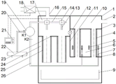
Fig. 1 is a schematic view of the overall structure of an embodiment of the present invention.
FIG. 2 is a schematic view of the ash removal ring structure of the present invention.
Fig. 3 is a schematic view of the inside of the telescopic cylinder of the present invention.
Fig. 4 is a schematic view of the interior of the flow stabilizer valve of the present invention.
Fig. 5 is a schematic diagram of the control system of the present invention.
In the figure: 1. the dust removal device comprises a box body, 2 parts of an air inlet pipe, 3 parts of an upper pattern plate, 4 parts of a staggered filter cartridge, 5 parts of a dust removal ring, 6 parts of a staggered filter chamber, 7 parts of a telescopic cylinder, 8 parts of a lower pattern plate, 9 parts of a dust collection device, 10 parts of an air inlet chamber, 11 parts of a middle partition plate, 12 parts of an air stabilizing valve, 13 parts of a nozzle, 14 parts of a pulse valve, 15 parts of an injection pipe, 16 parts of an air outlet pipe, 17 parts of a clean room, 18 parts of a fan, 19 parts of an air bag, 20 parts of an air pipe I, 21 parts of a controller, 22 parts of an air compressor, 23 parts of a pattern plate, 24 parts of an end filter chamber, 25 parts of an end filter cartridge, 26 parts of an air pipe II, 27 parts of a fixing rod I, 28 parts of a fixing rod II, 701 parts of a telescopic rod, 702 parts of a cylinder body, 703 parts of a cylinder body, 704 parts of a threaded rod, 1201 parts of an air hole, a wind sensing plate, 1202 parts of a connecting rod, 1203 parts of a wind screen plate, 1204 parts of a spring, 1205 parts of a threaded rod, a knob, and a threaded rod.
Detailed Description
The invention is further illustrated below:
referring to figures 1-5 of the drawings,
with reference to fig. 1 and 5, the staggered filtration-end filtration composite dust removal system comprises an air inlet chamber 10, a staggered filtration chamber 6, an end filtration chamber 24, a clean room 17, an air inlet pipe 2, an air outlet pipe 16, a staggered filtration type filter cylinder 4, an end filtration type filter cylinder 25, an ash removal ring 5, a telescopic cylinder 7, an air pipe i 20, an air pipe ii 26, a fixing rod i27, a fixing rod ii 28, a nozzle 13, a pulse valve 14, an injection pipe 15, a controller 21, an air stabilizing valve (12), an air bag 19, a fan 18, an air compressor 22 and an ash collecting device 9;
four spaces, namely an air inlet chamber 10, a staggered filter chamber 6, an end filter chamber 24 and a clean room 17, are sequentially arranged in the box body 1 according to the flow direction of main airflow;
the air inlet chamber 10 is a space formed by a middle partition plate 11, an upper pattern plate 3 and the inner wall of the box body 1, and an air inlet pipe 2 is arranged on the right side of the air inlet chamber 10 and provided with an opening in the box body 1;
the staggered filtering chamber 6 is a space formed by a middle partition plate 11, an upper pattern plate 3, a lower pattern plate 8 and the inner wall of the box body 1, a staggered filtering type filtering cylinder 4 is arranged in the staggered filtering chamber 6, the staggered filtering type filtering cylinder 4 is installed between the upper pattern plate 3 and the lower pattern plate 8, an ash cleaning ring 5 is sleeved on the periphery of the staggered filtering type filtering cylinder 4, the ash cleaning ring 5 is connected with a telescopic rod 701 of a telescopic cylinder 7, an air hole 703 is formed in the bottom of the telescopic cylinder 7 and connected with an air pipe II 26, the air pipe II 26 is connected with an air bag 19, a valve K2 is installed on the air pipe II 26, and the valve K2 is connected with a controller 21;
the end filter chamber 24 is a space formed by the middle partition plate 11, the lower pattern plate 8, the pattern plate 23 and the inner wall of the box body 1, an end filter type filter cylinder 25 is arranged in the end filter chamber 24, the end filter type filter cylinder 25 is installed below the pattern plate 23 in a hanging mode, and the opening in the top of the end filter type filter cylinder 25 corresponds to the middle opening position of the pattern plate 23;
the clean room 17 is a space formed by the middle partition plate 11, the pattern plate 23 and the box body 1, a nozzle 13, a pulse valve 14 and a blowing pipe 15 are arranged in the clean room 17, the nozzle 13 is installed on the blowing pipe 15 through the pulse valve 14, the opening of the nozzle 13 is opposite to the opening of the top of the end filter type filter cylinder 25, the blowing pipe 15 is connected with an air bag 19, the air bag 19 is connected with an air compressor 22 through an air pipe I20, the air pipe I20 is provided with a valve K1, the valve K1 is connected with a controller 21, the pulse valve 14 is also connected with the controller 21, an air outlet pipe 16 is installed on an opening of the box body 1 at the top of the clean room 17, a fan 18 is installed on the air outlet pipe 16, and the fan 18 is connected with the controller 21;
a hole is formed in the middle partition plate 11, so that the staggered filtering chamber 6 is communicated with the clean room 17, and an air stabilizing valve 12 is installed at the hole;
an ash collecting device 9 is arranged below the inner part of the box body 1, the ash collecting device 9 can be detached, and the ash collecting device 9 is of a square structure with a hollow top opening.
Referring to fig. 2, the ash removing ring 5 is provided with two holes, a fixing rod I27 and a fixing rod ii 28 penetrate through the two holes, two ends of the fixing rod I27 and two ends of the fixing rod ii 28 are both fixed between the upper flower plate 3 and the lower flower plate 8, the telescopic cylinder 7 is mounted on the lower flower plate 8, and the bottom of the telescopic cylinder 7 is provided with an air hole 703 connected with an air pipe ii 26; the dust cleaning ring 5 moves between the upper pattern plate 3 and the lower pattern plate 8.
Referring to fig. 3, the telescopic cylinder 7 is composed of a cylinder body 702 and a support rod 704, a telescopic rod 701 and an air hole 703 are arranged in the cylinder body 702, and compressed air enters from the air hole 703 to push the telescopic rod 701 to move upwards; when the air pressure of the compressed air is changed, the telescopic rod 701 moves down.
With reference to fig. 4, an air-sensitive plate 1201, a connecting rod 1202, an air blocking plate 1203, a spring 1204, a threaded rod 1205 and a knob 1206 are arranged inside the air-stabilizing valve 12, and the air-sensitive plate 1201 is structured as an upper plane and a lower convex curved surface; knob 1206 connection threaded rod 1205, threaded rod 1205 lower extreme coupling spring 1204, accessible knob 1206 adjust the degree of compression of spring 1204 on deep bead 1203, and then control different amount of wind steady state values.
Specific example 2:
when dust is removed, the fan 18 and the air compressor 22 are started, and the air volume of the dust-containing air flow is recorded as Q under the negative pressure action of the fan 18 T From the air inlet duct 2 into the air inlet chamber 10 and then on into the misfilter cartridge 4.
In the staggered filter cartridge 4, part of the air flow enters the staggered filter chamber 6 through the side wall of the staggered filter cartridge 4, and the part of the air flow is marked as Q c The dust in the air flow is intercepted by the side wall of the wrong filtering type filter cylinder 4 and is collected on the inner surface of the wrong filtering type filter cylinder 4 to form a dust cake, and the dust cake is attached by the drag force of the air flow passing through the side wall of the wrong filtering type filter cylinder 4 and the adhesion force of the inner surface of the wrong filtering type filter cylinder 4 on one hand and the shearing force of the air flow axially flowing downwards in the wrong filtering type filter cylinder 4 on the other hand. Part of the attached dust falls off the dust cake and reenters the air flow under the action of the shearing force, and the dust concentration of the dust-containing air flow of the staggered filter cartridge 4 is increased due to the shunting of part of the air flow.
The dust-laden air flow axially through the staggered filter cartridge 4 is marked by the air flow Q d (Q c +Q d =Q T ) And enters the end filter chamber 24.
In the end filter chamber 24, the airflow rate Q d The dust in the dust-containing air flow is filtered and blocked on the outer surface of the end filter type filter cylinder 25 to form a dust cake;
clean airflow quantity Q in staggered filtering chamber 6 c The clean airflow quantity Q entering the clean room 17 through the air stabilizing valve 12 and coming out of the upper opening of the end filter chamber 24 d And the mixture is converged and discharged through an air outlet pipe 16 and a fan 18.
In the staggered filtering chamber 6, the dust cake on the inner surface of the staggered filtering type filtering cylinder 4 is subjected to the combined action of gravity, axial wind flow shearing force, radial wind flow drag force and cylinder wall adhesion force, if the thickness of the dust cake is too high, the shearing force action of the axial downward flowing wind flow in the staggered filtering type filtering cylinder 4 on the dust cake is more obvious, so that the dust cake falls off, and finally the thickness of the dust cake on the inner surface of the staggered filtering type filtering cylinder 4 tends to be stable.
In the end filter chamber 24, dust on the surface of the end filter type filter cartridge 25 gradually gathers, and the air quantity Q passing through the cross filter chamber 6 increases with the increase of the filter resistance of the end filter type filter cartridge 25 c An attempt to increase the air volume, i.e. the air volume passing through the air stabilizing valve 12, will increase the pressure difference between the upper and lower sides of the air-sensitive plate 1201 due to the bernoulli effect, so that the air-sensitive plate 1201 is forced to moveAnd the wind shield 1203 moves downwards through the connecting rod 1202, so that the section of the wind flow channel of the wind stabilizing valve 12 is reduced, and the outlet wind quantity Q is reduced c Remain stable, thereby Q d Also keeps stable, finally leads the staggered filtration-end filtration composite dust removal system to work stably.
When the staggered filtration-end filtration composite dust removal system is used for removing dust,
step 1: cleaning ash by using a staggered filter cartridge 4;
and when the K1 is closed and the K2 is opened, the compressed air in the air bag 19 is transmitted to the telescopic cylinder 7 through the air pipe II 26, and the compressed air enters from the air hole 703 to push the telescopic rod 701 to move upwards. Because the flow channel of the air hole 703 is small, compressed air passes through the air hole slowly at a constant speed, the dust removal ring 5 can slowly move up to the top of the staggered filtration type filter cylinder 4 at a constant speed, in the side wall area of the staggered filtration type filter cylinder 4 correspondingly surrounded by the dust removal ring 5, air flow can not pass through the side wall of the staggered filtration type filter cylinder 4, namely the drag force of the dust cake on the inner surface of the staggered filtration type filter cylinder on the radial air flow of the filter cylinder disappears, at the moment, under the shearing action of the axial downward air flow of the filter cylinder, the dust cake on the inner surface of the staggered filtration type filter cylinder 4 is easily peeled off and falls, and dust removal is realized.
Step 2: the end filter type filter cylinder 25 is used for cleaning ash;
closing K2, controlling the pulse valve 14 to be opened by the controller 21, enabling compressed gas in the air bag 19 to be sprayed out through the spray pipe 15 and the nozzle 13, enabling pulse jet flow to impact the bottom of the end filter type filter cylinder 25, converting dynamic pressure of the pulse jet flow into static pressure required by ash removal, removing ash from the end filter type filter cylinder 25, and closing the pulse valve 14 after ash removal of the end filter type filter cylinder 25 is completed;
the filtration resistance of the end filter type filter cartridge 25 is reduced after the ash is removed, and the air quantity passing through the end filter chamber 24 is attempted to be increased so as to stagger the air quantity Q of the filter chamber 6 c Attempts have been made to get smaller. Once the air volume of the staggered filtering chamber 6 is reduced, under the bernoulli effect, the upward force applied to the air sensing plate 1201 inside the air stabilizing valve 12 is reduced, the wind blocking plate 1203 moves upward through the connecting rod 1202, the section of the air flow channel of the air stabilizing valve 12 is increased, and the outlet air volume Q is further increased c Remain stable, thereby Q d Also keeps stable, finally leads the staggered filtration-end filtration composite dust removal system to work stably.
And 3, step 3: resetting the ash removal device of the staggered filtering chamber 6;
k2 is opened, due to the consumption of the spraying of the nozzle 13, the air pressure in the air bag 19 is reduced, the compressed air in the cylinder body 702 flows back into the air bag 19 through the air hole 703 and the air pipe II 26, the recovery of the air is realized, therefore, the air pressure in the cylinder body 702 is insufficient, the telescopic rod 701 moves downwards, the ash removing ring 5 is driven to move downwards to the bottom of the staggered filter type filter cylinder 4, and then the K2 is closed.
And 4, step 4: make-up air bag 19 pressure;
and K1 is opened, and the air compressor 22 pressurizes the air bag 19 to clear ash in the next round.
The dust cleaned in the cross filter chamber 6 and the end filter chamber 24 falls into the dust collecting device 9 below the box body 1 to be intensively discharged.
The above description is only an embodiment of the present invention, and is not intended to limit the scope of the present invention, and all equivalent modifications made by the present invention and the contents of the accompanying drawings or directly or indirectly applied to the related technical fields are included in the scope of the present invention.
Claims (5)
1. Wrong compound dust pelletizing system of straining-end is strained, its characterized in that: the air filter comprises a box body (1), wherein four spaces of an air inlet chamber (10), a staggered filter chamber (6), an end filter chamber (24) and a clean room (17) are sequentially arranged in the box body (1) according to the flow direction of main airflow;
the air inlet chamber (10) is formed by a middle partition plate (11), an upper pattern plate (3) and the inner wall of the box body (1) to form a space, and an air inlet pipe (2) is arranged on the right side wall of the air inlet chamber (10) in a hole mode;
the staggered filtering chamber (6) is a space formed by a middle partition plate (11), an upper pattern plate (3), a lower pattern plate (8) and the inner wall of a box body (1), a plurality of staggered filtering type filtering cylinders (4) are arranged in the staggered filtering chamber (6), the staggered filtering type filtering cylinders (4) are installed between the upper pattern plate (3) and the lower pattern plate (8), ash removing rings (5) are sleeved outside the staggered filtering type filtering cylinders (4), the radial wind flow force of filter cakes in corresponding areas is weakened through the covering of the ash removing rings, the adhesion of the filter cakes is reduced, the staggered filtering type filtering cylinders are peeled under the shearing action of downstream air flow, the bottom ends of the ash removing rings (5) are connected with the outer ends of telescopic rods (701) of telescopic cylinders (7), air holes (703) connected with one end of an air pipe II (26) are formed in the bottom of the telescopic cylinders (7), the other end of the air pipe II (26) is connected with an air bag (19), a valve K2 is installed on the air pipe II (26), and the valve K2 is electrically connected with a controller (21);
the end filter chamber (24) is formed by a middle partition plate (11), a lower pattern plate (8), a pattern plate (23) and the inner wall of the box body (1) to form a space, a plurality of end filter type filter cylinders (25) are arranged in the end filter chamber (24), the end filter type filter cylinders (25) are hung and installed below the pattern plate (23), and the top openings of the end filter type filter cylinders correspond to the middle hole positions of the pattern plate (23);
the cleaning room (17) is a space formed by an intermediate partition plate (11), a pattern plate (23) and the inner wall of the box body (1), a nozzle (13), a pulse valve (14) and a blowing pipe (15) are arranged in the cleaning room (17), the nozzle (13) is installed on the blowing pipe (15) through the pulse valve (14), the opening of the nozzle (13) is opposite to the opening of the top of an end filter type filter cylinder (25), the blowing pipe (15) is connected with an air bag (19), the air bag (19) is connected with an air compressor (22) through an air pipe I (20), a valve K1 is installed on the air pipe I (20), the valve K1 and the pulse valve (14) are respectively and electrically connected with a controller (21), an air outlet pipe (16) is installed at the top of the cleaning room (17), a fan (18) is installed on the air outlet pipe (16), and the fan (18) is electrically connected with the controller (21);
an opening for communicating the staggered filter chamber (6) with the clean room (17) is formed in the middle partition plate (11), and an air stabilizing valve (12) is installed at the opening;
an ash collecting device (9) which can be detached is arranged below the inner cavity of the box body (1).
2. The mis-filtration-end filtration composite dust removal system as claimed in claim 1, wherein: the ash removing ring (5) is provided with a fixing rod I (27) and a fixing rod II (28) which penetrate through sliding holes, two ends of the fixing rod I (27) and two ends of the fixing rod II (28) are respectively fixed on the upper pattern plate (3) and the lower pattern plate (8), the telescopic cylinder (7) is installed on the lower pattern plate (8), and the bottom of the telescopic cylinder (7) is provided with an air hole (703) which is connected with an air pipe II (26); the ash removing ring (5) is driven to move between the upper pattern plate (3) and the lower pattern plate (8) through a telescopic cylinder (7).
3. The cross-filtration-end-filtration composite dust removal system according to claim 2, wherein: the telescopic cylinder (7) comprises a cylinder body (702) and a supporting rod (704), the supporting rod (704) is fixed at the bottom of the cylinder body (702), and the bottom of the supporting rod (704) is fixed on the lower pattern plate (8); an expansion rod (701) and an air hole (703) are arranged in the cylinder body (702), and compressed air enters from the air hole (703) to push the expansion rod (701) to move upwards; when the air pressure of the compressed air is changed, the telescopic rod (701) moves downwards.
4. The cross-filtration-end-filtration composite dust removal system according to claim 1, wherein: an air sensing plate (1201), a connecting rod (1202), an air blocking plate (1203), a spring (1204), a threaded rod (1205) and a knob (1206) are arranged inside the air stabilizing valve (12), and the air sensing plate (1201) is of a structure with an upper plane and a lower convex curved surface; the utility model discloses a wind-resistant plate, including wind-resistant plate (1201), knob (1206), threaded rod (1205), spring (1204) are connected to the threaded rod (1205) lower extreme, the lower extreme of spring (1204) with the upper end of deep bead (1203) is connected, the lower extreme of deep bead (1203) pass through connecting rod (1202) with the lateral wall of wind-sensitive plate (1201) is connected, can adjust the compression degree of spring (1204) on deep bead (1203) through knob (1206), and then control different amount of wind stable values.
5. A method for controlling a cross-filtration and end-filtration composite dust removal system as claimed in any one of claims 1 to 4, comprising the steps of:
s1: starting a fan (18) and an air compressor (22), and carrying out filtering and dust removing operation by a dust removing system;
s2: ash removal is carried out on the staggered filter cartridge (4); closing the K1, opening the K2, conveying compressed air of the air bag (19) to the telescopic cylinder (7) through the air pipe II (26), driving the ash removal ring (5) to slowly move upwards at a constant speed by the telescopic cylinder (7), and stripping dust cakes in a coverage area corresponding to the ash removal ring (5) in the staggered filter type filter cylinder (4);
s3: the end filter type filter cylinder (25) is used for cleaning ash; closing K2, opening a pulse valve (14), spraying compressed gas in the air bag (19) through a spray pipe (15) through a nozzle (13), cleaning ash for the end-filter type filter cylinder (25), and closing the pulse valve (14) after the end-filter type filter cylinder (25) finishes cleaning ash;
s4: resetting the ash removal device of the staggered filter chamber (6); opening K2, moving the ash removal ring (5) downwards to the bottom of the staggered filter cylinder (4), and closing K2;
s5: supplementing the pressure of the air bag (19); and K1 is opened, and the air compressor (22) supplies air to and pressurizes the air bag (19).
Priority Applications (1)
| Application Number | Priority Date | Filing Date | Title |
|---|---|---|---|
| CN202111346445.1A CN114159907B (en) | 2021-11-15 | 2021-11-15 | Staggered filtration-end filtration composite dust removal system and control method thereof |
Applications Claiming Priority (1)
| Application Number | Priority Date | Filing Date | Title |
|---|---|---|---|
| CN202111346445.1A CN114159907B (en) | 2021-11-15 | 2021-11-15 | Staggered filtration-end filtration composite dust removal system and control method thereof |
Publications (2)
| Publication Number | Publication Date |
|---|---|
| CN114159907A CN114159907A (en) | 2022-03-11 |
| CN114159907B true CN114159907B (en) | 2023-04-07 |
Family
ID=80478912
Family Applications (1)
| Application Number | Title | Priority Date | Filing Date |
|---|---|---|---|
| CN202111346445.1A Active CN114159907B (en) | 2021-11-15 | 2021-11-15 | Staggered filtration-end filtration composite dust removal system and control method thereof |
Country Status (1)
| Country | Link |
|---|---|
| CN (1) | CN114159907B (en) |
Families Citing this family (1)
| Publication number | Priority date | Publication date | Assignee | Title |
|---|---|---|---|---|
| CN117919863B (en) * | 2024-03-25 | 2024-06-04 | 广东天赐湾实验室装备制造有限公司 | Dust collection method of fume hood, electronic equipment and storage medium |
Family Cites Families (4)
| Publication number | Priority date | Publication date | Assignee | Title |
|---|---|---|---|---|
| CN2789668Y (en) * | 2005-04-18 | 2006-06-21 | 李永强 | Wind pressure type self-adaptive gas constant flow valve |
| RU2539156C1 (en) * | 2013-07-08 | 2015-01-10 | Владимир Евгеньевич Воскресенский | Bag-cartridge filter to clean air from mechanical impurities |
| CN213101316U (en) * | 2020-06-10 | 2021-05-04 | 福建东亚环保科技股份有限公司 | Multistage pulse dust collector |
| CN112473309B (en) * | 2020-12-22 | 2024-05-03 | 南昌大学 | Combined dust collection system with cross-flow filtration |
-
2021
- 2021-11-15 CN CN202111346445.1A patent/CN114159907B/en active Active
Also Published As
| Publication number | Publication date |
|---|---|
| CN114159907A (en) | 2022-03-11 |
Similar Documents
| Publication | Publication Date | Title |
|---|---|---|
| CN204502649U (en) | A kind of spray air dust arrester | |
| CN107158868A (en) | A kind of industrial dedusting device | |
| CN208852556U (en) | A kind of purification separation system for blast furnace gas thermal energy recycling | |
| CN114159907B (en) | Staggered filtration-end filtration composite dust removal system and control method thereof | |
| CN202036899U (en) | Filter cylinder type off-line ash removal dust collector | |
| CN201524509U (en) | Zincum powder dust collecting device | |
| CN107150000B (en) | Static powder spraying equipment with branch type air duct | |
| CN102861485A (en) | Pulse bag type dust collector of gas tank | |
| CN202087473U (en) | Environment-friendly self-cleaning spray house | |
| CN101716444A (en) | Compartmental static normal-pressure type pulse bag type dust remover | |
| CN200974003Y (en) | Pulse blowing cloth bag type dust precipitator | |
| CN104707462B (en) | A kind of waste gas produced in time preparing fertilizer removes ammonia and the method for dust | |
| CN202909570U (en) | Movable bag type dust removal device | |
| CN105999910B (en) | A kind of fly-ash filter dust arrester | |
| CN210889017U (en) | Coal dust collecting and removing device for coal mine tunnel | |
| CN204447556U (en) | With the dedusting fan of multiple impacts formula gas-liquid separation | |
| CN202724958U (en) | Pulse bag-type dust collector | |
| CN213995171U (en) | Bag collector with from deashing function | |
| CN211513829U (en) | Desulfurization and denitrification boiler dust remover | |
| CN205598798U (en) | Unit pulse bag dust collector | |
| CN107983022A (en) | A kind of dust treatment device by compressed air purifying filter core | |
| CN212236395U (en) | Separate-bin offline continuous ash removal pulse dust collector | |
| CN112337210A (en) | Bag collector with from deashing function | |
| CN107456811A (en) | A kind of sack cleaner | |
| CN205832861U (en) | A kind of energy-conserving and environment-protective dust pelletizing system |
Legal Events
| Date | Code | Title | Description |
|---|---|---|---|
| PB01 | Publication | ||
| PB01 | Publication | ||
| SE01 | Entry into force of request for substantive examination | ||
| SE01 | Entry into force of request for substantive examination | ||
| GR01 | Patent grant | ||
| GR01 | Patent grant |