CN114152209A - Boiler large plate girder deflection measuring device and method - Google Patents
Boiler large plate girder deflection measuring device and method Download PDFInfo
- Publication number
- CN114152209A CN114152209A CN202111497067.7A CN202111497067A CN114152209A CN 114152209 A CN114152209 A CN 114152209A CN 202111497067 A CN202111497067 A CN 202111497067A CN 114152209 A CN114152209 A CN 114152209A
- Authority
- CN
- China
- Prior art keywords
- far infrared
- measuring device
- distance measuring
- infrared distance
- scale
- Prior art date
- Legal status (The legal status is an assumption and is not a legal conclusion. Google has not performed a legal analysis and makes no representation as to the accuracy of the status listed.)
- Withdrawn
Links
Images


Classifications
-
- G—PHYSICS
- G01—MEASURING; TESTING
- G01B—MEASURING LENGTH, THICKNESS OR SIMILAR LINEAR DIMENSIONS; MEASURING ANGLES; MEASURING AREAS; MEASURING IRREGULARITIES OF SURFACES OR CONTOURS
- G01B11/00—Measuring arrangements characterised by the use of optical techniques
- G01B11/16—Measuring arrangements characterised by the use of optical techniques for measuring the deformation in a solid, e.g. optical strain gauge
Landscapes
- Physics & Mathematics (AREA)
- General Physics & Mathematics (AREA)
- Length Measuring Devices By Optical Means (AREA)
- Length Measuring Devices With Unspecified Measuring Means (AREA)
Abstract
The invention discloses a boiler girder deflection measuring device and method. The device comprises a far infrared distance measuring device and an indicating scale, wherein the upper end and the lower end of the far infrared distance measuring device are magnetic bases, and the upper end and the lower end of the far infrared distance measuring device are connected by a support; the bottom of the magnetic base is provided with universal pulleys. A far infrared distance measuring instrument is arranged in the hollow frame of the far infrared distance measuring device, the far infrared distance measuring instrument is connected with the first magnetic upper base, and the left side and the right side of the far infrared distance measuring instrument are respectively provided with a distance measuring head; be equipped with the scale in the indicator scale cavity frame, link to each other with second magnetism upper base, the scale of scale is two positive and negative directions. The far infrared distance measuring instrument respectively sends laser to the left and right sides, and laser projects on the indicator scale below (or above) the boiler slab beam both ends, through scale instruction reading, the distance of far infrared distance measuring instrument luminous center to the slab beam, slab beam length, calculates the deflection value of boiler slab beam. The invention has simple structure, high measurement precision, convenient carrying, no need of power supply and water source and simple operation.
Description
Technical Field
The invention belongs to the field of deflection measurement of large-span beam workpieces, and particularly relates to a device and a method for measuring deflection of a large plate beam of a boiler.
Background
The boiler girder is an important load-bearing part of the boiler. The vertical deflection of the large plate girder of the boiler is measured before the large plate girder of the boiler is installed and loaded, before the hydraulic pressure test of the boiler, after the water is supplied in the hydraulic pressure test of the boiler, after the water is discharged in the hydraulic pressure test of the boiler and before the ignition of the boiler is started. When the in-service boiler is regularly checked, the deflection change condition of the large plate girder of the boiler is also measured. At present, a boiler girder is usually measured by a level or a total station before bearing, after bearing, the upper plane of an I-shaped girder is provided with more attached welding parts, and the lower plane of the I-shaped girder is provided with a plurality of suspension rods, so that inconvenience is brought to measurement of the level or the total station. The measuring method adopts far infrared ray (one kind of laser) to match with special tools for measurement, and has simple process and high measuring precision.
Disclosure of Invention
The invention aims to overcome the defects in the background technology and provide a novel boiler large plate beam deflection measuring device which does not need a power supply and a water source, does not need a mechanical rotating part, has simple equipment, is firm and durable and does not need professional training and study for operating personnel. The test process is easy, the precision is high, and the efficiency is high.
The technical scheme of the invention is as follows:
the boiler large plate beam deflection measuring device comprises a far infrared ray distance measuring device and an indicating scale. The far infrared distance measuring device and the indicating scale are designed by adopting a vertical hollow cuboid frame, the upper end and the lower end of the far infrared distance measuring device are provided with magnetic bases with magnetic switches, and the magnetic upper bases are fixedly connected with each other by adopting four supporting columns; and four universal pulleys are arranged at the bottom of the magnetic base and used for moving the measuring device during measurement.
The far infrared distance measuring device is characterized in that a far infrared distance measuring instrument is arranged in a hollow frame of the far infrared distance measuring device, the far infrared distance measuring instrument is connected with a fixing piece fixed on a first magnetic upper base through a connecting piece, and distance measuring heads are respectively arranged on the left side and the right side.
A staff gauge is arranged in a hollow frame of the indicating staff gauge, a lifting lug is arranged on the second magnetic upper base, a clamping piece is arranged below the lifting lug and used for connecting the staff gauge and the lifting lug, and a lead block is arranged below the staff gauge; the scale is provided with scales in the positive direction and the negative direction.
A boiler large plate girder deflection measuring method adopts the measuring device, and specifically comprises the following steps:
the far infrared distancer respectively sends laser light in same horizontal direction the left and right sides, and on light projected the indicator scale of boiler slab roof beam both ends below (or top), through reading the instruction reading of indicator scale, the distance (this value is the definite value) that far infrared distancer luminous center arrives the slab roof beam is subtracted again to the difference between two readings, just can calculate the downwarping numerical value. The sum of the distances from the far infrared distance measuring instrument to the two rulers is the length of the large plate beam, and the deflection value of the large plate beam of the boiler is obtained by dividing the downwarp value by the length of the large plate beam.
The invention has the beneficial effects that:
the deflection measuring device provided by the invention has the advantages of simple structure, no mechanical rotating part, firmness, durability, high measuring precision, convenience in carrying, no need of a power supply and a water source, and simplicity and easiness in learning in operation.
Drawings
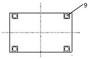
FIG. 1 is a front view of a far infrared distance measuring device;
FIG. 2 is a side view showing the structure of a far infrared distance measuring apparatus;
FIG. 3 is a top view of a far infrared distance measuring device;
FIG. 4 is a front view of the far infrared distance meter;
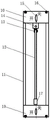
FIG. 5 is an elevation view of an indicating scale;
FIG. 6 is a side elevational view of the indicating scale;
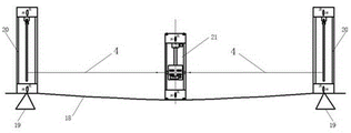
FIG. 7 is a schematic view of the deflection values measured under a girder;
FIG. 8 is a schematic view of the deflection values measured above the girder;
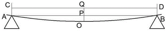
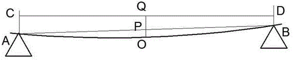
FIG. 9 is a schematic view of the principle of measuring below a boiler main beam with both ends of the beam at the same level;
FIG. 10 is a schematic view of the principle of measurement below a boiler main beam when the two ends of the beam are not at the same level;
FIG. 11 is a schematic view of the principle of measuring above a boiler main beam with both ends of the beam at the same level;
FIG. 12 is a schematic view of the principle of measurement above a boiler main beam when both ends of the beam are not at the same level.
In the figure: 1. a first magnetic base; 2. a first support; 3. a far infrared distance meter; 4. a far infrared ray; 5. a connecting member; 6. a fixing member; 7. a locking member; 8. a first magnetic switch; 9. a first universal pulley; 10. a second magnetic mount; 11. a second support; 12. a scale; 13. a clamping member; 14. lifting lugs; 15. a second magnetic switch; 16. a second universal pulley; 17. lead blocks; 18. a boiler main beam; 19. supporting the large plate girder; 20. an indication scale; 21. far infrared rangefinder.
Detailed Description
The present invention will be further described with reference to the drawings attached to the specification, but the present invention is not limited to the following examples.
The invention relates to a boiler large plate beam deflection measuring device which comprises a far infrared ray distance measuring device and an indicating scale.
As shown in fig. 1, 2 and 3, the far infrared ranging device is designed by a vertical hollow cuboid frame, the upper end and the lower end of the far infrared ranging device are provided with first magnetic bases 1 with first magnetic switches 8, and the middle of the far infrared ranging device is fixed at four corners by four first supporting columns 2 and connected with the two first magnetic bases 1.
The first magnetic bases 1 are arranged up and down respectively and are provided with first magnetic switches 8 respectively, and the first magnetic switches are used for controlling the attraction of the magnetic bases; four corners of the bottom of each first magnetic base 1 are respectively provided with 4 first universal pulleys 9, and after the first magnetic bases 1 are adsorbed on the large plate beam by magnetic force, the measuring device can be moved by the first universal pulleys 9.
The far infrared distance measuring device is characterized in that a far infrared distance measuring instrument 3 is arranged in a hollow frame of the far infrared distance measuring device, the far infrared distance measuring instruments 3 are arranged on the same horizontal direction, distance measuring heads are respectively arranged on the left side and the right side and are respectively used for emitting far infrared rays 4, and the sum of the distance measuring of the two far infrared rays is the length of a large plate beam. As shown in fig. 4, the far infrared distance meter 3 includes: light source emitting heads 3-1 and 3-4 of the far infrared distance meter 3; the distance between the left side and the right side is 3-2, the distance between the right side and the left side is 3-3, and the sum of the numerical values of the left side display screen and the right side display screen is the length of the large plate girder; 3-5 parts of a scale difference display screen and 3-6 parts of a power switch key; scale data input key regions 3-7; and 3-8 parts of a deflection calculation value display screen.
The far infrared distance measuring instrument 3 is connected with a fixing piece 6 fixed on the first magnetic base 1 through a connecting piece 5. One end of the connecting piece 5 is a threaded joint and is connected with the far infrared distance measuring instrument 3 through threads, and the other end of the connecting piece is a spherical joint. The hollow inside of the fixing piece 6 is matched with the spherical joint of the connecting piece 5, so that the connecting piece 5 can be always vertical under the action of gravity; and the locking piece 7 of the spherical joint is used for keeping the connecting piece 5 vertical and then locking and not shaking any more, so that the position of the far infrared distance meter 3 is ensured to be fixed.
Fig. 5 and 6 are a front view and a side view of the indication scale, and the second magnetic bases 10 are respectively provided one above the other and are respectively provided with a second magnetic switch 15 for controlling the attraction force of the magnetic bases; four angles at the bottom of each second magnetic base 10 are respectively provided with 4 second universal pulleys 16, and after the second magnetic bases 10 are adsorbed on the large plate beam by magnetic force, the indicating scale can be moved by the second universal pulleys 16. The upper and lower bases of the second magnetic base 10 are identical to the first magnetic base 1 in fig. 1. Four second pillars 11 are provided between the second magnetic bases 10.
The upper base of the second magnetic base 10 is provided with a lifting lug 14, a clamping piece 13 is installed below the lifting lug 14 and used for connecting the scale 12 and the lifting lug 14, the clamping piece 13 can rotate on a rotating shaft on the lifting lug 14, and the lifting lug 14 is used for hanging the scale 12. A lead 17 is provided under the scale 12 to ensure the natural perpendicularity of the scale 12. Scales in the front direction and the back direction are arranged on the scale 12 and used for reading. When the indicating scale is arranged below the large plate girder to measure the deflection, the reading of the scale is read from top to bottom; when the indicating scale is arranged above the large plate girder to measure deflection, the reading of the scale is read from bottom to top.
The working principle of the invention is as follows:
the deflection measuring device can measure the deflection value of the large plate girder below the large plate girder and can also measure the deflection value of the large plate girder above the large plate girder, and can adapt to different measuring environments. The far infrared distancer respectively sends a red laser light in same horizontal direction the left and right sides, and on the scale of light projection below boiler slab roof beam both ends (or top), the scale can read the instruction reading, and the distance (this value is the definite value) that far infrared distancer luminous center arrives the slab roof beam is subtracted again to the difference between two readings, just can calculate the downwarping numerical value. The sum of the distances from the far infrared distance measuring instrument to the two rulers is the length of the large plate beam, and the lower deflection value is divided by the length of the large plate beam to form the deflection value. DL/T612 and 2017 stipulate that the beam deflection value of the suspension main plate is unqualified when the beam deflection value exceeds 1/850 and is qualified when the beam deflection value is less than 1/850.
Fig. 7 is a schematic view of the deflection measuring device under the large plate girder. At both ends of the plate girder 18, plate girder supports 19 are provided. The indicator scale 20 is adsorbed below the two ends of the large plate beam 18, the far infrared distance measuring device 21 is adsorbed at the middle position below the large plate beam 18, and the far infrared rays 4 emitted by the far infrared distance measuring device 21 are respectively projected on the scale on the same horizontal line.
Fig. 8 is a schematic view of the measurement of the deflection measuring device above the large plate girder. At both ends of the girder 18 there are also girder supports 19. The indicator scale 20 adsorbs in the top at big board roof beam 18 both ends, and far infrared ranging device 21 adsorbs in the top intermediate position of big board roof beam 18, and far infrared 4 that far infrared ranging device 21 sent throws respectively on the scale on same water flat line.
Fig. 9 shows a case where the deflection measuring device is under the girder, and both ends of the girder are supported on the same horizontal line. The numerical values of AC and BD are the indicated values of the infrared rays emitted by the far infrared distance measuring instrument on the left side and the right side projected on the scale plus the height value of the magnetic base, and the indicated values of the scale read a row of scales which are gradually increased from top to bottom; since both ends of the girder are supported on the same horizontal line, AC ═ BD; 0Q is the vertical distance from the infrared ray of the far infrared distance measuring instrument to the large plate beam, and the value is a fixed value, namely the height value of the far infrared distance measuring instrument; the O point is the central point of the length direction of the large plate beam, the distance indicated values on two sides are seen through moving the far infrared distance measuring instrument, and the adjustment is continuously moved until the far infrared distance measuring instrument is just positioned at the central position of the length direction of the large plate beam. PQ = AC = BD, and deflection value OP = PQ-OQ.
Fig. 10 shows a case where the deflection measuring device is under the girder and both ends of the girder are not supported on the same horizontal line. The numerical values of AC and BD are the indicated value of the far infrared rays emitted by the far infrared distance meter on the left and right sides projected on the scale plus the height value of the magnetic base, and the indicated value of the scale reads a row of scales which are gradually increased from top to bottom; because the two ends of the large plate girder are not supported on the same horizontal line, AC is not equal to BD; 0Q is the vertical distance from the infrared ray of the far infrared distance measuring instrument to the large plate beam, and the value is a fixed value, namely the height value of the far infrared distance measuring instrument; the O point is the central point of the length direction of the large plate beam, the distance indicated values on two sides are seen through moving the far infrared distance measuring instrument, and the adjustment is continuously moved until the far infrared distance measuring instrument is just positioned at the central position of the length direction of the large plate beam. According to the trapezoidal median theorem, PQ = (AC + BD)/2, and the flexibility value OP = PQ-OQ.
Fig. 11 shows a case where the deflection measuring device is above the girder, and both ends of the girder are supported on the same horizontal line. The numerical values of AC and BD are the indicated values of the infrared rays emitted by the far infrared distance measuring instrument on the left side and the right side projected on the scale and the height of the magnetic base, and at the moment, the indicated values of the scale read a row of scales which are gradually increased from bottom to top; since both ends of the girder are supported on the same horizontal line, AC ═ BD; 0Q is the vertical distance from the infrared ray of the far infrared distance measuring instrument to the large plate beam, and the value is a fixed value, namely the height value of the far infrared distance measuring instrument; the O point is the central point of the length direction of the large plate beam, the distance indicated values on two sides are seen through moving the far infrared distance measuring instrument, and the adjustment is continuously moved until the far infrared distance measuring instrument is just positioned at the central position of the length direction of the large plate beam. PQ = AC = BD, and deflection value OP = OQ-PQ.
Fig. 12 shows the case where the deflection measuring device is above the girder, and the both ends of the girder are not supported on the same horizontal line. The numerical values of AC and BD are the indicated values of the infrared rays emitted by the far infrared distance measuring instrument on the left side and the right side projected on the scale and the height of the magnetic base, and at the moment, the indicated values of the scale read a row of scales which are gradually increased from bottom to top; because the two ends of the large plate girder are not supported on the same horizontal line, AC is not equal to BD; 0Q is the vertical distance from the infrared ray of the far infrared distance measuring instrument to the large plate beam, and the value is a fixed value, namely the height value of the far infrared distance measuring instrument; the O point is the central point of the length direction of the large plate beam, the distance indicated values on two sides are seen through moving the far infrared distance measuring instrument, and the adjustment is continuously moved until the far infrared distance measuring instrument is just positioned at the central position of the length direction of the large plate beam. According to the trapezoidal median theorem, PQ = (AC + BD)/2, and the flexibility value OP = OQ-PQ.
Because the length of the large plate girder can be measured by the measuring tool at the same time, the bending value OP/the length of the large plate girder is qualified when the bending value OP/the length of the large plate girder is less than 1/850, and is unqualified when the bending value OP/the length of the large plate girder exceeds 1/850. The calculation formula may be integrated in a calculation chip of the distance meter, and the deflection calculation value display screen in fig. 4 may display the calculation value OP and whether it is qualified.
Claims (7)
1. The utility model provides a boiler large plate roof beam amount of deflection measuring device, includes far infrared range unit and indicator scale, its characterized in that:
the far infrared distance measuring device and the indicating scale are designed by adopting a vertical hollow cuboid frame, the upper end and the lower end of the far infrared distance measuring device are provided with magnetic bases with magnetic switches, and the magnetic upper bases are fixedly connected with each other by adopting four supporting columns; the bottom of the magnetic base is provided with four universal pulleys for moving the measuring device during measurement;
a far infrared distance meter is arranged in a hollow frame of the far infrared distance measuring device, the far infrared distance meter is connected with a fixing piece fixed on a first magnetic upper base through a connecting piece, and the left side and the right side of the far infrared distance measuring device are respectively provided with a distance measuring head;
a staff gauge is arranged in a hollow frame of the indicating staff gauge, a lifting lug is arranged on the second magnetic upper base, a clamping piece is arranged below the lifting lug and used for connecting the staff gauge and the lifting lug, and a lead block is arranged below the staff gauge; the scale is provided with scales in the positive direction and the negative direction.
2. The deflection measuring device of the boiler girder according to claim 1, characterized in that:
the indicator scale is adsorbed at two ends of the large plate beam, and the far infrared distance measuring device is adsorbed at the middle position of the large plate beam.
3. The deflection measuring device of the boiler girder according to claim 1, characterized in that:
one end of the connecting piece is a round joint, and the other end of the connecting piece is a spherical joint; the spherical joint is matched with the hollow part of the fixing piece, so that the connecting piece is always vertical under the action of gravity.
4. The deflection measuring device of the boiler girder according to claim 1, characterized in that:
the fixing piece is provided with a locking piece for keeping the connecting piece vertical and then locked without shaking.
5. The deflection measuring device of the boiler girder according to claim 1, characterized in that:
the deflection measuring device can measure the deflection value of the large plate girder below the large plate girder and can also measure the deflection value of the large plate girder above the large plate girder.
6. The deflection measuring device of the boiler girder according to claim 1, characterized in that:
the far infrared distance measuring instrument comprises two distance measuring heads, a left distance display screen, a right distance display screen, a scale difference display screen, a power switch key, a scale data input key area and a deflectometer calculation value display screen which are oppositely arranged.
7. A method for measuring the deflection of a boiler girder adopts the deflection measuring device of the boiler girder of claim 1, and is characterized in that:
the far infrared distancer respectively sends laser light in same horizontal direction the left and right sides, and laser light projects on the indicator scale of boiler slab roof beam both ends below or top, through reading the instruction reading of indicator scale, makes the difference to two instruction readings and subtracts the distance that far infrared distancer luminous center arrives the slab roof beam again, calculates and obtains the downwarping numerical value, and the downwarping numerical value divides the length of slab roof beam just obtains the flexibility value of boiler slab roof beam.
Priority Applications (1)
| Application Number | Priority Date | Filing Date | Title |
|---|---|---|---|
| CN202111497067.7A CN114152209A (en) | 2021-12-09 | 2021-12-09 | Boiler large plate girder deflection measuring device and method |
Applications Claiming Priority (1)
| Application Number | Priority Date | Filing Date | Title |
|---|---|---|---|
| CN202111497067.7A CN114152209A (en) | 2021-12-09 | 2021-12-09 | Boiler large plate girder deflection measuring device and method |
Publications (1)
| Publication Number | Publication Date |
|---|---|
| CN114152209A true CN114152209A (en) | 2022-03-08 |
Family
ID=80454084
Family Applications (1)
| Application Number | Title | Priority Date | Filing Date |
|---|---|---|---|
| CN202111497067.7A Withdrawn CN114152209A (en) | 2021-12-09 | 2021-12-09 | Boiler large plate girder deflection measuring device and method |
Country Status (1)
| Country | Link |
|---|---|
| CN (1) | CN114152209A (en) |
Cited By (1)
| Publication number | Priority date | Publication date | Assignee | Title |
|---|---|---|---|---|
| CN115824539A (en) * | 2023-02-14 | 2023-03-21 | 滨州市特种设备检验研究院 | Large plate girder deflection measuring system |
-
2021
- 2021-12-09 CN CN202111497067.7A patent/CN114152209A/en not_active Withdrawn
Cited By (1)
| Publication number | Priority date | Publication date | Assignee | Title |
|---|---|---|---|---|
| CN115824539A (en) * | 2023-02-14 | 2023-03-21 | 滨州市特种设备检验研究院 | Large plate girder deflection measuring system |
Similar Documents
| Publication | Publication Date | Title |
|---|---|---|
| CN212712432U (en) | Portable tower crane and construction elevator standard festival straightness monitoring devices that hangs down | |
| CN201318935Y (en) | Laser arch measuring instrument | |
| CN104506139B (en) | Multifunctional laser device for concentrating photovoltaic test | |
| CN202661047U (en) | Rail gauge measuring device for large-span overhead rail of traveling crane | |
| CN114152209A (en) | Boiler large plate girder deflection measuring device and method | |
| CN203116706U (en) | Steel rail automatic leveling laser detection device | |
| CN201413107Y (en) | Base measurement device for large-scale precise rolling mill | |
| CN109631761A (en) | A kind of square plate geometric tolerance detection device | |
| CN106959216B (en) | Tramcar bogie static load test device | |
| CN209147885U (en) | Height measurement device in a kind of container | |
| CN208567788U (en) | More lens video measuring instruments | |
| CN202562480U (en) | Laser-reflection level | |
| CN205879134U (en) | Straightness accuracy comprehensive testing device | |
| CN201837333U (en) | Suspended vertical displacement measuring device | |
| CN106352841A (en) | Flatness detecting device for elevator skirt panel | |
| CN112880706B (en) | Vertical reference instrument | |
| CN210773910U (en) | Defect position measuring instrument for transformer substation | |
| CN213579900U (en) | Measurement calibrating device | |
| CN209673041U (en) | A kind of square plate geometric tolerance detection device | |
| CN209043171U (en) | Relative altitude measuring instrument | |
| CN207779320U (en) | Warpage measuring device | |
| CN201592321U (en) | Laser positioning device for welding machine frame of wire drawing machine | |
| CN204902830U (en) | Perpendicular detection device of bridge | |
| CN221859562U (en) | Laser measuring device | |
| CN212721441U (en) | Automatic leveling centering rod for engineering measurement |
Legal Events
| Date | Code | Title | Description |
|---|---|---|---|
| PB01 | Publication | ||
| PB01 | Publication | ||
| SE01 | Entry into force of request for substantive examination | ||
| SE01 | Entry into force of request for substantive examination | ||
| WW01 | Invention patent application withdrawn after publication | ||
| WW01 | Invention patent application withdrawn after publication |
Application publication date: 20220308 |