CN114132576A - E-commerce logistics automatic packaging and sorting device and logistics adhesive tape flatting device - Google Patents
E-commerce logistics automatic packaging and sorting device and logistics adhesive tape flatting device Download PDFInfo
- Publication number
- CN114132576A CN114132576A CN202111485932.6A CN202111485932A CN114132576A CN 114132576 A CN114132576 A CN 114132576A CN 202111485932 A CN202111485932 A CN 202111485932A CN 114132576 A CN114132576 A CN 114132576A
- Authority
- CN
- China
- Prior art keywords
- block
- square
- adhesive tape
- cantilever
- touch
- Prior art date
- Legal status (The legal status is an assumption and is not a legal conclusion. Google has not performed a legal analysis and makes no representation as to the accuracy of the status listed.)
- Granted
Links
Images


Classifications
-
- B—PERFORMING OPERATIONS; TRANSPORTING
- B65—CONVEYING; PACKING; STORING; HANDLING THIN OR FILAMENTARY MATERIAL
- B65B—MACHINES, APPARATUS OR DEVICES FOR, OR METHODS OF, PACKAGING ARTICLES OR MATERIALS; UNPACKING
- B65B51/00—Devices for, or methods of, sealing or securing package folds or closures; Devices for gathering or twisting wrappers, or necks of bags
- B65B51/04—Applying separate sealing or securing members, e.g. clips
- B65B51/06—Applying adhesive tape
- B65B51/067—Applying adhesive tape to the closure flaps of boxes
-
- B—PERFORMING OPERATIONS; TRANSPORTING
- B65—CONVEYING; PACKING; STORING; HANDLING THIN OR FILAMENTARY MATERIAL
- B65B—MACHINES, APPARATUS OR DEVICES FOR, OR METHODS OF, PACKAGING ARTICLES OR MATERIALS; UNPACKING
- B65B61/00—Auxiliary devices, not otherwise provided for, for operating on sheets, blanks, webs, binding material, containers or packages
- B65B61/04—Auxiliary devices, not otherwise provided for, for operating on sheets, blanks, webs, binding material, containers or packages for severing webs, or for separating joined packages
- B65B61/06—Auxiliary devices, not otherwise provided for, for operating on sheets, blanks, webs, binding material, containers or packages for severing webs, or for separating joined packages by cutting
-
- B—PERFORMING OPERATIONS; TRANSPORTING
- B65—CONVEYING; PACKING; STORING; HANDLING THIN OR FILAMENTARY MATERIAL
- B65B—MACHINES, APPARATUS OR DEVICES FOR, OR METHODS OF, PACKAGING ARTICLES OR MATERIALS; UNPACKING
- B65B61/00—Auxiliary devices, not otherwise provided for, for operating on sheets, blanks, webs, binding material, containers or packages
- B65B61/24—Auxiliary devices, not otherwise provided for, for operating on sheets, blanks, webs, binding material, containers or packages for shaping or reshaping completed packages
Abstract
The invention relates to the field of packing devices, and discloses an automatic packing and sorting device for electronic commerce logistics and an adhesive tape flatting device for the logistics, the adhesive tape flatting device for logistics comprises a square block, a touch block, a first moving plate, a second moving plate and a sliding hole, the square block is arranged in a hollow way, the touch block is vertically and slidably arranged in the middle of the bottom of the square block, the sliding holes are symmetrically arranged at the two sides of the touch block at the bottom of the square block, the first moving plate is arranged at one side of the sliding hole close to the touch block in a sliding manner, the second moving plate is arranged on one side of the sliding hole far away from the touch block in a sliding mode, when the touch block moves upwards, the first moving plate and the second moving plate move in opposite directions to finish flatting the adhesive tape, remove bubbles in the adhesive tape, and automatically reset after the touch block moves upwards.
Description
Technical Field
The invention relates to the technical field of packing devices, in particular to an automatic packing and sorting device for electronic commerce logistics and an adhesive tape flatting device for logistics.
Background
The e-commerce refers to transaction activities and related service activities performed in an electronic transaction mode on the internet, an intranet and a value-added network, and with the rapid development of e-commerce in recent years, the demand of people for online shopping is increasing, so that the work demand for logistics packaging is also increasing.
The Chinese patent publication No. CN110576996A discloses a packing carton packing operation adhesive tape sealing device, which relates to the technical field of production and packing and comprises a sticking mechanism and a frame, wherein the frame is set to be a workbench structure, the left side of the top end face of the frame is provided with a box sealing frame, one end of the box sealing frame is provided with a feeding hole, and the other end of the box sealing frame is provided with a discharging hole; has the advantages of improving the bonding firmness of the adhesive tape and the like.
The device adopts the mode that removes along the U-shaped groove to carry out the sticky tape bonding through setting up the U-shaped groove when using, can't realize the synchronous laminating of both sides sticky tape, can't guarantee that the laminating degree of both sides sticky tape is unanimous, leads to relatively poor to holistic laminating effect, and can't realize the synchronous laminating of both sides sticky tape, has certain use limitation.
Therefore, it is necessary to provide an automatic packaging and sorting device for e-commerce logistics and a tape flatting device for logistics to solve the above technical problems.
Disclosure of Invention
The invention aims to provide an automatic E-commerce logistics packing and sorting device and a logistics adhesive tape flattening device, and aims to solve the problems that synchronous gluing of adhesive tapes on two sides cannot be achieved in the background technology, the gluing effect of the whole carton is poor, and the like.
For realizing above-mentioned purpose, the design makes the sticky tape be close to the carton of treating the packing, and both sides still keep removing after contacting with the opening, finally are the packing of the completion carton of falling the U-shaped, accomplish the sticky tape laminating to the in-process that removes to both sides for compact structure, efficiency is higher, and both sides keep laminating in step, and the effect is better.
Based on the above thought, the invention provides the following technical scheme: the utility model provides a commodity circulation is with sticky tape device that flattens, includes the square, touches movable block, first movable plate, second movable plate and sliding hole, the square cavity sets up, touch the vertical slip of movable block set up in the bottom intermediate position of square, the sliding hole is seted up symmetrically in the square bottom touch the both sides of movable block, first movable plate slides and sets up the sliding hole is close to touch one side of movable block, the second movable plate slides and sets up the sliding hole is kept away from touch one side of movable block, when touching movable block rebound, first movable plate with the second movable plate removes in opposite directions, accomplishes the subsides of sticky tape, gets rid of the inside bubble of sticky tape, touches the piece and moves the back on, first movable plate and second movable plate automatic playback.
Preferably, the touch screen further comprises a first magnetic block, a touch rod and an elastic piece, wherein the touch rod is fixedly arranged at the upper end of the touch block, the elastic piece is fixedly arranged at the middle position of the top wall of the square block and the upper end of the touch rod, and the first magnetic block is fixedly arranged on two sides of the touch rod.
Preferably, still include first carriage release lever, second carriage release lever, first rack, second rack, bull stick and gear, first carriage release lever fixed set up in the upside of first movable plate, the upper end of first carriage release lever with the roof sliding connection of square, the second carriage release lever is fixed to be set up the upper end of second movable plate, the upper end of second carriage release lever with the roof sliding connection of square, first carriage release lever is to keeping away from the fixed being provided with of direction of touching the piece first rack, the second carriage release lever is to being close to the fixed being provided with of direction of touching the piece the second rack, first rack with mesh has in the middle of the second rack the gear, the upside of gear is fixed to be equipped with the bull stick, the bull stick with the roof of square rotates to be connected.
Preferably, the telescopic device further comprises a spring telescopic rod which is fixedly arranged in the middle of the two first moving rods.
Preferably, the device further comprises a first flatting strip, a second flatting strip and a second magnetic block, wherein the first flatting strip is fixedly arranged on one side of the first moving plate, the second flatting strip is fixedly arranged on one side of the second moving plate, the second magnetic block is fixedly arranged on one side of the first moving rod, which is close to the first moving rod, when the touch block moves upwards, the first magnetic block and the second magnetic block are in the same level, the magnetism of the first magnetic block and the magnetism of the second magnetic block are mutually exclusive, when the touch block moves upwards, the first magnetic block and the second magnetic block are in the same level, the first moving rod moves towards the direction far away from the touch block, meanwhile, the first moving plate drives the first flatting strip to move towards the direction far away from the touch block, meanwhile, the first rack rotating gear is driven, the second rack is driven to move towards the direction close to the touch block, meanwhile, the second moving plate drives the second flatting strip to move towards the direction close to the touch block, the first flatting strip and the second flatting strip move in opposite directions to be attached to the adhesive tape to be flat, air bubbles in the adhesive tape are removed, after the trigger state of the touch block is relieved, the first magnetic block and the second magnetic block are not in the same straight line, and under the action of the telescopic rod of the spring, the two first moving rods return to the original positions to drive the second moving rods to return to the original positions.
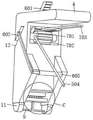
An automatic E-commerce logistics packaging and sorting device comprises a workbench, a partition plate and a tape mechanism which are fixedly connected in sequence, wherein a first air cylinder is fixedly connected inside the partition plate, two second air cylinders are rotatably installed inside the partition plate, the adhesive tape packaging and sorting device comprises an adhesive tape flatting device for logistics, square blocks and cantilevers are respectively installed on output shafts of the first air cylinder and the second air cylinder, the two cantilevers are symmetrically arranged and are respectively rotatably connected with two side walls of the square blocks, a clamping assembly used for fixing the movable end of an adhesive tape is arranged on the cantilever far away from the tape mechanism, an arc-shaped block is slidably installed at the bottom of the cantilever, a cavity is formed in the surface of the cantilever in a penetrating mode, a transmission assembly is rotatably installed inside the cavity, and a sliding assembly which is in transmission connection with the transmission assembly and is obliquely arranged is slidably installed inside the cavity;
the second cylinder and the first cylinder are started simultaneously to drive the square block and the cantilever to descend, when the square block reaches a threshold value, the first cylinder closes the square block and is not moved, the second cylinder continues to drive the cantilever to descend so that the cantilever starts to rotate by taking the square block as a base point, and the logistics adhesive tape flatting device is arranged inside the square block.
Preferably, the transmission assembly comprises a short rod rotatably connected with the cavity, a gear in transmission connection with the sliding assembly is fixedly mounted on the outer surface of the short rod, and a main rack in rotation connection with the square block is in transmission connection with the gear.
Preferably, the surface of the main rack far away from the gear is abutted against the cavity wall of the cavity, and the main rack is positioned below the rotation base point of the cantilever relative to the square relative to the rotation base point of the square.
Preferably, the sliding assembly comprises a driven rack which is connected with the cantilever in a sliding mode and is in transmission connection with the transmission assembly, the driven rack is obliquely arranged and is fixedly provided with a U-shaped frame on the surface, and one end, far away from the driven rack, of the U-shaped frame is rotatably provided with a first pressing roller.
Drawings
The invention is further illustrated with reference to the following figures and examples:
FIG. 1 is a schematic view of the overall structure of the present invention;
FIG. 2 is a left side view of the block and cantilever of the present invention;
FIG. 3 is a right side perspective view of the right cantilever of the present invention;
FIG. 4 is an enlarged view of the structure at A in FIG. 3;
FIG. 5 is a left side perspective view of the right cantilever of the present invention;
FIG. 6 is an enlarged view of the structure at B in FIG. 5;
FIG. 7 is a schematic view of the clamp assembly of the present invention;
FIG. 8 is a right side perspective view of the left cantilever of the present invention;
FIG. 9 is a schematic view of a cutting assembly according to the present invention;
FIG. 10 is a schematic view of the moving assembly of the present invention;
FIG. 11 is a view of the adhesive tape leveling device for logistics according to the present invention;
FIG. 12 is a schematic view of the mating of the first and second racks of the present invention;
FIG. 13 is a bottom view of the dice of the present invention.
In the figure: 1. a work table; 2. a partition plate; 3. a square block; 4. a cantilever; 5. a moving assembly; 6. a sliding assembly; 7. a transmission assembly; 8. a clamping assembly; 9. a cutting assembly; 10. a third spring; 11. an arc-shaped block; 12. a cavity; 13. a first cylinder; 14. a second cylinder; 15. a tape mechanism; 16. a groove; 501. a slide bar; 502. a second spring; 503. a second press roll; 504. pulling a rope; 601. a slave rack; 602. a U-shaped frame; 603. a first press roll; 701. a short bar; 702. a gear; 703. a main rack; 801. a base plate; 802. a first spring; 803. oiled paper; 901. a connecting rod; 902. a cutter plate; 903. a U-shaped block; 17. the logistics are pasted with a tape and flattened device; 171. a touch block; 172. a first moving plate; 173. first pasting flat strips; 174. a slide hole; 175. a second moving plate; 176. second pasting the flat strips; 177. a first movable bar; 178. a first magnetic block; 179. a second magnetic block; 1710. a touch rod is touched; 1711. an elastic member; 1712. a second movable bar; 1713. a first rack; 1714. a second rack; 1715. a rotating rod; 1716. a gear; 1717. the spring is a telescopic rod.
Detailed Description
The first embodiment is as follows:
referring to fig. 1 to 3 and 7, an embodiment of the present invention provides an automatic packaging and sorting apparatus for e-commerce logistics: the packaging machine comprises a workbench 1, a partition plate 2 fixedly connected with the workbench 1 and a tape mechanism 15 fixedly connected with the partition plate 2, wherein the workbench 1 is used for placing cartons of tapes to be packaged, the tape mechanism 15 is used for storing and conveying the tapes, and the tape mechanism 15 is the existing mature technology and is not described in detail here.
A first air cylinder 13 and two symmetrically distributed second air cylinders 14 are arranged inside the partition plate 2, the first air cylinder 13 is fixedly connected with the partition plate 2, the second air cylinders 14 are rotatably connected with the partition plate 2, and the two second air cylinders 14 are symmetrically arranged by taking the first air cylinder 13 as a center; the output shaft of the first cylinder 13 is fixedly provided with a square block 3, the output shaft of the second cylinder 14 is rotatably provided with a cantilever 4, the cantilever 4 is in an L-shaped design, one side close to the square block 3 is provided with a bevel edge, and the two cantilevers 4 are symmetrically arranged and are respectively and rotatably connected with two side walls of the square block 3; the bottom of the right cantilever 4 is provided with a clamping component 8 for fixing the movable end of the adhesive tape, when the adhesive tape is pulled out from the adhesive tape mechanism 15, the adhesive tape passes through the left cantilever 4 and the lower part of the square 3 and then reaches the clamping component 8 of the right cantilever 4 to realize the limiting, the adhesive tape is in a state that the adhesive surface faces downwards, and the adhesive tape is in a state of being attached to the bottom of the square 3; the equal slidable mounting in bottom of every cantilever 4 has arc piece 11, and the spout that is used for placing arc piece 11 is offered to the bottom of cantilever 4, can slide from top to bottom for cantilever 4 along the spout after 11 atresss of arc piece, is convenient for the quick reset after 11 atresss of arc piece, and fixed mounting has third spring 10 between spout and arc piece 11.
A cavity 12 is formed in the side wall of the cantilever 4 in a penetrating manner, a transmission component 7 is rotatably arranged in the cavity 12, a sliding component 6 in transmission connection with the transmission component 7 is slidably arranged in the cavity 12, and the sliding component 6 is obliquely arranged; when the first cylinder 13 drives the block 3 to descend, the block 3 drives the adhesive tape to descend to contact with the opening of the carton, and when the second cylinder 14 and the first cylinder 13 are kept synchronous and drive the cantilever 4 to descend, the cantilever 4 drives the adhesive tape to descend to correspond to the side walls of the two sides of the carton; when the block 3 is contacted with the opening of the carton, the first cylinder 13 is closed, the block 3 does not move, the second cylinder 14 is continuously started to drive the cantilever 4 to descend, the cantilever 4 starts to rotate by taking the block 3 as a base point, when the second cylinder 14 is closed until the outer surface of the arc-shaped block 11 is contacted with the side wall of the carton, the cantilever 4 does not move, when the outer surface of the arc-shaped block 11 is contacted with the side wall of the carton, the sliding component 6 just corresponds to the position of the side wall of the carton and keeps a parallel state, the bevel edge of the cantilever 4 is also kept parallel to the side wall of the carton, and the arc-shaped blocks 11 at the two sides play a role in positioning the cantilever 4.
In the present embodiment, it is preferable that: when in use, the carton to be packaged is firstly placed on the workbench 1, then the adhesive tape is pulled out from the adhesive tape mechanism 15, so that the adhesive tape passes through the left cantilever 4 and the right cantilever 4 below the square 3, and effective limiting is realized by the clamping component 8; then, a first air cylinder 13 and a second air cylinder 14 are started simultaneously, the first air cylinder 13 drives the square 3 to descend, the second air cylinder 14 drives the cantilever 4 to descend and keep synchronization with the square 3, and the square 3 and the two cantilevers 4 drive the adhesive tape to descend together; after the square 3 contacts with the opening of the carton, the first cylinder 13 is closed, the square 3 does not move any more, the second cylinder 14 continues to drive the cantilever 4 to descend, the cantilever 4 starts to rotate by taking the square 3 as a base point, and after the cantilever 4 drives the arc block 11 to rotate, so that the arc block 11 contacts with the side wall of the carton, the second cylinder 14 is closed, the cantilever 4 does not move any more, and the adhesive tape is in an inverted U shape and is attached to the opening and the side wall of the carton.
When the cantilever 4 rotates with the block 3 as a base point, the transmission assembly 7 starts to rotate, the transmission assembly 7 is in transmission connection with the sliding assembly 6, so that the transmission assembly 7 slides downwards relative to the cantilever 4, in the sliding process, the sliding assembly 6 pulls out the movable end of the adhesive tape from the clamping assembly 8, simultaneously the adhesive tape is completely attached to two sides of the carton, and finally the adhesive tape is cut off by a tool such as scissors. Through the matching of the structures such as the square block 3, the cantilever 4, the transmission component 7, the sliding component 6 and the like, the adhesive tape can automatically finish packaging the opening of the carton, and can be respectively adhered to two sides of the carton, so that the labor burden of workers is reduced, and meanwhile, the adhesive tapes on the two sides are synchronously adhered, so that the efficiency is higher, and the overall effect is better; but also can effectively reduce the loss to the sticky tape, because need not to change the sticky tape round packing round carton, only realize the adhesion to carton opening and close both sides, so still realized the effective utilization to the resource, holistic practicality is higher.
Example two:
referring to fig. 1 to 7, in the first embodiment, the transmission assembly 7 includes a short rod 701 rotatably connected to the cavity 12, and the short rod 701 is disposed in parallel in front and back; the outer surface of the short rod 701 is fixedly provided with a gear 702 in transmission connection with the sliding assembly 6, the gear 702 is in transmission connection with a main rack 703 in rotation connection with the square 3, the surface of the main rack 703, which is far away from the gear 702, is abutted against the cavity wall of the cavity 12, so that the main rack 703 is always kept in a transmission state with the gear 702, and the rotation base point of the main rack 703 is positioned below the cantilever 4; the gear 702 has a larger thickness and can be meshed with the main rack 703 and the sliding component 6 for transmission, one end of the main rack 703, which is far away from the gear 702, rotates with the side wall of the block 3, and the main rack 703 is perpendicular to the block 3 in an initial state.
The sliding assembly 6 comprises a driven rack 601 which is connected with the cantilever 4 in a sliding way and is in transmission connection with the gear 702, the driven rack 601 and the cantilever 4 are arranged in an inclined way, and the inclined direction is consistent with the inclined edge of the cantilever 4; a U-shaped frame 602 is fixedly arranged on the front surface of the rack 601, and the U-shaped frame 602 extends to the outside of the cantilever 4 from one end of the rack 601 and is rotatably provided with a first pressing roller 603; first compression roller 603 corresponds with the size adaptation and the position of sticky tape for the laminating of sticky tape and carton lateral wall is leveled, when following rack 601 along cantilever 4 inclined sliding, can drive the vertical decline of hypotenuse along cantilever 4 of first compression roller 603 through U-shaped frame 602.
Clamping assembly 8 includes bottom plate 801, fixed mounting has first spring 802 between the bottom of bottom plate 801 and cantilever 4, a reset after the location and the bottom plate 801 that are used for realizing bottom plate 801 remove, bottom plate 801 is close to cantilever 4's fixed surface installs oiled paper 803, when the sticky tape expansion end is gluey face down and leads to bottom plate 801, its glued face does not adhere with oiled paper 803, only through first spring 802, bottom plate 801 and cantilever 4 bottom fold and realize pressing from both sides tight spacing, oiled paper 803 can not break away from with the convenient later stage of sticky tape adhesion, here oiled paper 803 also can use other materials that can not the sticky tape adhesion.
In the present embodiment, it is preferable that: after the carton is put, the adhesive tape is pulled out of the adhesive tape mechanism 15 and passes through the left cantilever 4 and the lower part of the block 3 to the right cantilever 4, then the bottom plate 801 is pulled down to move the adhesive tape between the oiled paper 803 and the cantilever 4, and then the bottom plate 801 is loosened to be matched with the first spring 802, the oiled paper 803 and the right cantilever 4 to clamp the adhesive tape; then, the first air cylinder 13 and the second air cylinder 14 are started simultaneously, the square block 3 and the cantilever 4 are driven to descend synchronously, and the square block 3 and the two cantilevers 4 drive the adhesive tape to descend together; after the square 3 contacts with the opening of the carton, the first cylinder 13 stops and the square 3 does not move at the moment, the second cylinder 14 continues to drive the cantilever 4 to descend, so that the cantilever 4 starts to rotate by taking the square 3 as a base point, and after the cantilever 4 drives the arc block 11 to rotate and the outer surface of the arc block 11 contacts with the side wall of the carton, the second cylinder 14 stops and the cantilever 4 does not move at the moment, so that the adhesive tape is in an inverted U shape and is attached to the opening and the side wall of the carton.
When the cantilever 4 rotates with the block 3 as a base point, the cantilever 4 drives the short rod 701 and the gear 702 to synchronously rotate through the cavity 12, the cavity 12 simultaneously drives the main rack 703 to rotate along the base point of the block 3, because the base point of the main rack 703 is located below the cantilever 4, the main rack 703 extends out of the cantilever 4 along the cavity 12 and drives the gear 702 to rotate clockwise, the gear 702 drives the slave rack 601 to slide down along the cantilever 4 in an inclined manner, and the slave rack 601 drives the first press roller 603 to vertically descend along the cantilever 4 through the U-shaped frame 602; in the sliding process, the first pressing roller 603 descends to press the adhesive tape, so that the adhesive tape can be attached to the side wall of the carton, on the one hand, the movable end of the adhesive tape can be pulled out from between the oil paper 803 and the bottom of the cantilever 4, finally, the adhesive tape and the side wall of the carton become completely and smoothly attached by the first pressing roller 603, and finally, the adhesive tape is cut off from the left side by a tool such as scissors.
Through the matching of the structures of the cantilever 4, the main rack 703, the auxiliary rack 601, the U-shaped frame 602 and the like, the first compression rollers 603 on the two sides can be driven to vertically descend, so that the adhesive tapes on the two sides can be smoothly attached to the side wall of the carton, the later leveling by hands of workers is not needed, the labor burden of the workers is reduced, the adhesive tapes on the two sides are synchronously attached, and the efficiency is higher and better; through the matching of the structures of the square block 3, the cantilever 4, the arc-shaped block 11 and the like, the adhesive tape can automatically finish the opening packaging of the carton in an inverted U shape, and the degree of automation is high; and the adhesion is realized only to carton opening and close both sides to this device's packaging mode, need not to change the sticky tape round carton packing, consequently can effectively reduce the loss to the sticky tape, realized the effective utilization to the sticky tape resource, the sticky tape that the single packing was used becomes still less, also make single roll of sticky tape can use longer time, pack more cartons, can also reduce the number of times that the staff changed the sticky tape, further alleviate staff's burden, more demands in the in-service use have been satisfied.
Example three:
referring to fig. 1 to 7 and 10, on the basis of the second embodiment, a groove 16 is formed at the bottom of the block 3, and two symmetrically-arranged moving assemblies 5 are slidably mounted inside the groove 16 for smoothing out an adhesive tape at an opening of a carton.
The moving assembly 5 comprises slide bars 501 in sliding fit with the grooves 16, elongated slots which are formed in the square 3 and communicated with the grooves 16 are used for sliding the slide bars 501, the slide bars 501 can horizontally slide along the square 3 through the elongated slots, second springs 502 are fixedly arranged between the opposite sides of the two slide bars 501 and the walls of the elongated slots for resetting the slide bars 501, second compression rollers 503 are rotatably arranged on the outer surfaces of the slide bars 501 for leveling adhesive tapes at openings of cartons, the second compression rollers 503 are arranged in the same way as the first compression rollers 603, pull ropes 504 are fixedly arranged on the surfaces of the slide bars 501, the movable ends of the pull ropes 504 are fixedly wound on the outer surfaces of short bars 701 on the other sides, namely the pull ropes 504 of the slide bars 501 on the left side are connected with the short bars 701 on the right side, and the pull ropes 504 of the slide bars 501 on the right side are connected with the short bars 701 on the left side; the part of the pulling rope 504 in the groove 16 is horizontally arranged, which can facilitate pulling the sliding rod 501 and the second pressing roller 503, and when in a tensioned state, the pulling rope 504 is horizontally arranged in the groove 16, and extends from the square 3 and inclines upwards to correspond to the short rod 701.
In the present embodiment, it is preferable that: when the cantilever 4 rotates with the square 3 as a base point, the distance between the cantilever 4 and the square 3 decreases, and at this time, the pulling rope 504 is released from the original tensioning state, and under the action of the second spring 502, the sliding rod 501 drives the second pressing roller 503 to move towards the side wall of the square 3; under the matching of the structures of the cantilever 4, the cavity 12, the gear 702, the main rack 703 and the like, the short rod 701 rotates clockwise to release the pull rope 504, and the released pull rope 504 is matched with the distance when the tension is released, so that the two slide bars 501 and the second press roller 503 can move to the edges of two sides of the square 3, and the integral smoothing of the adhesive tape at the opening of the carton can be realized; the rotation of the short rod 701 realizes the rotation of the gear 702, so that the movement of the first pressing roller 603 driven by the rack 601 is realized, the release of the pull rope 504 is realized, and the movement distance of the pull rope 504 is ensured. Compared with the second embodiment, through the matching of the structures such as the sliding rod 501, the second spring 502, the pull rope 504 and the second press roller 503, the smooth attachment of the adhesive tape at the opening of the carton can be automatically realized, the second press roller 503 can move to the edges of two sides of the square 3 due to the arrangement of the short rod 701 and the pull rope 504, the adhesive tape at the opening of the carton can be extruded by the second press roller 503 when moving, the integral leveling of the adhesive tape at the opening of the carton is further realized, and the integral leveling of the adhesive tapes at two sides and the adhesive tape at the opening is synchronously performed by matching with the integral leveling of two sides of the first press roller 603, so that the integral attachment effect of the packaged adhesive tape can be ensured, the efficiency is higher, and the integral working efficiency is higher because the adhesive tapes at two sides and the opening are synchronously performed; the adhesive tapes at the opening and the two sides of the carton are not required to be pressed flat by hands by workers, and the labor burden of the workers is further reduced.
Example four:
referring to fig. 1 to 10, on the basis of the third embodiment, a cutting assembly 9 fixedly connected with a left arc block 11 is disposed at the bottom of the left cantilever 4, and is used for automatically cutting off the adhesive tape after packaging is completed, and the adhesive tape passes through the middle of the cutting assembly 9 when passing through the left cantilever 4.
The cutting assembly 9 comprises a connecting rod 901 fixedly connected with the left arc-shaped block 11 and a U-shaped block 903 fixedly connected with the bottom of the left cantilever 4, the connecting rod 901 is arranged in a T shape, two ends of the T shape are respectively connected with the two left arc-shaped blocks 11, the movement is more stable, the cutting effect is better, a cutter plate 902 is fixedly installed at the end part, far away from the corresponding arc-shaped block 11, of the T-shaped block, and the cutter plate 902 is the existing mature technology and is not described in detail herein; the cutters on the cutter plate 902 correspond to the notches in the U-shaped block 903 and pass between the cutter plate 902 and the U-shaped block 903 when the tape is in use.
In the present embodiment, it is preferable that: when the cantilever 4 rotates with the block 3 as a base point, the adhesive tape passing through the left cantilever 4 is in a V-shaped tightened state, and the first pressing rollers 603 on both sides can be driven to vertically descend along the cantilever 4 by the matching of the short rod 701, the gear 702, the main rack 703, the auxiliary rack 601, the U-shaped frame 602 and the like. In the process of sliding downwards, the first right pressing roller 603 enables the movable end of the adhesive tape to be pulled out from between the oiled paper 803 and the bottom of the cantilever 4, and the adhesive tape is squeezed to be completely attached to the right side wall of the carton; the first compression roller 603 on the left side extrudes the adhesive tape to enable the adhesive tape to be completely attached to the left side wall of the carton, meanwhile, the first compression roller 603 on the left side continuously descends to extrude the arc-shaped block 11 on the left side to enable the arc-shaped block to ascend along the cantilever 4, the arc-shaped block 11 on the left side drives the cutter plate 902 to ascend to enable the cutter to extrude the adhesive tape, and the notch of the U-shaped block 903 is matched to realize rapid cutting of the adhesive tape; when the first pressing roller 603 on the left side rises, the cutter plate 902 is also driven to rise, but no adhesive tape passes through the cutter plate and cannot be cut, the moving process of the first pressing roller 603 on the right side and the right arc-shaped block 11 is the same as that on the left side, and the first pressing roller 603 on the right side cannot fall down due to the sliding movement on the right side.
Through the first compression roller 603 in left side, arc piece 11, the cooperation of cutter board 902 and U-shaped piece 903 isotructure, when the first compression roller 603 in left side descends, not only can realize the level and smooth laminating of carton left side wall sticky tape, can also realize the auto-cutting to the sticky tape, compare in embodiment three, need not the staff and cut the sticky tape with the instrument, staff's work burden has further been alleviateed, the shearing work of sticky tape keeps unanimous with the laminating work of sticky tape simultaneously, accomplish the cutting along with the laminating finishes automatically, further improve work efficiency, and holistic degree of automation is higher, the suitability is stronger.
As a further improvement of the present embodiment: in practical use, a sanding block can be fixedly arranged on the surface of the cutter plate 902 close to the U-shaped block 903, and the sanding block corresponds to the surface of the U-shaped block 903.
When the connecting rod 901 drives the cutter plate 902 to ascend, the cutter plate 902 drives the sanding block to ascend synchronously, the sanding block abuts against the surface of the U-shaped block 903 to clamp the adhesive tape, and the cutter plate 902 is matched with the U-shaped block 903 to realize the cutting of the adhesive tape; through setting up cutter board 902 cooperation dull polish piece and U-shaped piece 903, not only can realize the automatic cutout to the sticky tape, can also realize spacing to cutting back sticky tape, avoid droing downwards of cutting back sticky tape, make things convenient for the staff to find the expansion end of sticky tape.
Example five:
referring to fig. 11-13, a device for flatting adhesive tapes for logistics includes a block 3, a touch block 171, a first moving plate 172, a second moving plate 175 and a sliding hole 174, where the block 3 is hollow, the touch block 171 is vertically and slidably disposed at a middle position of the bottom of the block 3, the sliding hole 174 is symmetrically disposed at two sides of the touch block 171 at the bottom of the block 3, the first moving plate 172 is slidably disposed at one side of the sliding hole 174 close to the touch block 171, the second moving plate 175 is slidably disposed at one side of the sliding hole 174 far from the touch block 171, when the touch block 171 moves upward, the first moving plate 172 and the second moving plate 175 move toward each other, flatly pasting the adhesive tapes on the moving plates is completed, bubbles inside the adhesive tapes are removed, and the first moving plate and the second moving plate automatically return to their positions after the touch block moves upward.
Specifically, still include first magnetic path 178, touch pole 1710 and elastic component 1711, touch pole 1710 is fixed to be set up touch block 171's upper end, elastic component 1711 is fixed to be set up square 3's roof with touch pole 1710's upper end intermediate position, first magnetic path 178 is fixed to be set up touch pole 1710's both sides.
In particular, a first moving bar 177, a second moving bar 1712, a first rack 1713, a second rack 1714, a rotating bar 1715 and a gear 1716, the first moving bar 177 is fixedly arranged on the upper side of the first moving plate 172, the upper end of the first moving bar 177 is slidably connected with the top wall of the block 3, the second moving rod 1712 is fixedly arranged at the upper end of the second moving plate 175, the upper end of the second moving rod 1712 is slidably connected with the top wall of the block 3, the first moving rod 177 is fixedly provided with the first rack 1713 in a direction away from the touch block 171, the second moving rod 1712 is fixedly provided with the second rack 1714 in a direction approaching the touch block 171, the gear 1716 is engaged between the first rack 1713 and the second rack 1714, the upper side of the gear 1716 is fixedly provided with the rotating rod 1715, and the rotating rod 1715 is rotatably connected with the top wall of the square 3.
Specifically, the device further comprises a spring telescopic rod 1717, and the spring telescopic rod 1717 is fixedly arranged in the middle of the two first moving rods 177.
Specifically, the device further comprises a first flatting strip 173, a second flatting strip 176 and a second magnetic block 179, wherein the first flatting strip 173 is fixedly arranged on one side of the first moving plate 172, the second flatting strip 176 is fixedly arranged on one side of the second moving plate 175, the second magnetic block 179 is fixedly arranged on one side of the first moving rod 177, which is close to each other, when the touch block 171 moves upwards, the first magnetic block 178 and the second magnetic block 179 are in the same level, the magnetism of the first magnetic block 178 and the magnetism of the second magnetic block 179 are mutually repelled, when the touch block moves upwards, the first magnetic block and the second magnetic block are in the same level, the first moving rod moves in a direction away from the touch block, meanwhile, the first moving plate drives the first flatting strip to move in a direction away from the touch block, simultaneously drives the first rack rotating gear to drive the second rack to move in a direction close to the touch block, and simultaneously, the second moving plate drives the second flatting strip to move in a direction close to the touch block, the first flatting strip and the second flatting strip move in opposite directions to be attached to the adhesive tape to be flat, air bubbles in the adhesive tape are removed, after the trigger state of the touch block is relieved, the first magnetic block and the second magnetic block are not in the same straight line, and under the action of the telescopic rod of the spring, the two first moving rods return to the original positions to drive the second moving rods to return to the original positions.
An automatic E-commerce logistics packaging and sorting device comprises a workbench, a partition plate and a tape mechanism which are fixedly connected in sequence, wherein a first air cylinder is fixedly connected inside the partition plate, two second air cylinders are rotatably installed inside the partition plate, the adhesive tape packaging and sorting device comprises an adhesive tape flatting device 17 for logistics, square blocks and cantilevers are respectively installed on output shafts of the first air cylinder and the second air cylinder, the two cantilevers are symmetrically arranged and are respectively rotatably connected with two side walls of the square blocks, a clamping assembly used for fixing the movable end of an adhesive tape is arranged on the cantilever far away from the tape mechanism, an arc-shaped block is slidably installed at the bottom of the cantilever, a cavity is formed in the surface of the cantilever in a penetrating mode, a transmission assembly is rotatably installed inside the cavity, and a sliding assembly which is in transmission connection with the transmission assembly and is obliquely arranged is slidably installed inside the cavity;
the second cylinder and the first cylinder are started simultaneously to drive the square block and the cantilever to descend, when the square block reaches a threshold value, the first cylinder closes the square block and is not moved, the second cylinder continues to drive the cantilever to descend so that the cantilever starts to rotate by taking the square block as a base point, and the logistics adhesive tape flattening device 17 is arranged inside the square block 3.
Specifically, the transmission assembly comprises a short rod rotatably connected with the cavity, a gear in transmission connection with the sliding assembly is fixedly mounted on the outer surface of the short rod, and a main rack in rotation connection with the square block is in transmission connection with the gear.
Specifically, the surface of the main rack, which is far away from the gear, is abutted against the cavity wall of the cavity, and the main rack is positioned below the rotation base point of the cantilever relative to the square relative to the rotation base point of the square.
Specifically, the sliding assembly comprises a driven rack which is connected with the cantilever in a sliding mode and is in transmission connection with the transmission assembly, a U-shaped frame is obliquely arranged from the rack and fixedly mounted on the surface of the driven rack, and a first pressing roller is rotatably mounted at one end, far away from the driven rack, of the U-shaped frame.
The working principle of the invention is as follows: when the adhesive tape clamping device is used, firstly, a carton to be packaged is placed on the workbench 1, then an adhesive tape is pulled out from the adhesive tape mechanism 15, so that the movable end of the adhesive tape passes through a position between the U-shaped block 903 and the cutter plate 902 below the left cantilever 4 and passes through a position between the lower part of the square block 3 and the right cantilever 4, and then the movable end of the adhesive tape is clamped through the matching of structures such as the bottom plate 801, the first spring 802, the oiled paper 803 and the right cantilever 4; and then, simultaneously starting the first air cylinder 13 and the second air cylinder 14, driving the square 3, the cantilever 4 and the adhesive tape to descend synchronously, when the square 3 is contacted with the opening of the carton, stopping the square 3 by the first air cylinder 13, keeping the cantilever 4 and the adhesive tapes on two sides to descend by the second air cylinder 14, enabling the cantilever 4 to start rotating by taking the square 3 as a base point, and when the outer surface of the arc-shaped block 11 below the cantilever 4 is contacted with the side wall of the carton, stopping the cantilever 4 by the second air cylinder 14, keeping the adhesive tapes still, and enabling the adhesive tapes to be attached to the opening and the side walls of the carton in an inverted U shape.
When the cantilever 4 rotates with the block 3 as a base point, the cantilever 4 drives the slave rack 601 to slide down along the cantilever 4 in an inclined manner through the matching of the structures such as the cavity 12, the short rod 701, the gear 702 and the main rack 703, and the slave rack 601 drives the first press roller 603 to vertically descend along the cantilever 4 through the U-shaped frame 602; in the process that the first press rollers 603 on the two sides slide downwards, the first press roller 603 on the right side enables the movable end of the adhesive tape to be pulled out from between the oiled paper 803 and the bottom of the cantilever 4, and the adhesive tape is squeezed to be completely attached to the right side wall of the carton; the left first pressing roller 603 extrudes the adhesive tape to enable the adhesive tape to be completely attached to the left side wall of the carton, meanwhile, the left first pressing roller 603 continuously descends to realize rapid cutting of the adhesive tape through the matching of the left arc-shaped block 11, the connecting rod 901, the cutter plate 902, the U-shaped block 903 and other structures, namely, the downward sliding of the two first pressing rollers 603 is realized, so that the integral leveling of the adhesive tapes on the two sides of the carton is realized, and the automatic cutting of the adhesive tapes after the packaging is finished is also realized.
When the cantilever 4 rotates with the square 3 as a base point, the distance between the cantilever 4 and the square 3 is reduced, at this time, the pull rope 504 is released from the tension state, and under the action of the second spring 502, the slide bar 501 drives the second press roller 503 to move towards the side wall of the square 3; because the pull rope 504 is released by clockwise rotation of the short rod 701, the released pull rope 504 is matched with the distance when the tension is released, so that the two sliding rods 501 and the second pressing roller 503 can move to the edges of two sides of the square 3, and the second pressing roller 503 can press the adhesive tape at the opening of the carton when moving, so that the adhesive tape at the opening of the carton can be integrally smoothed.
Claims (9)
1. The utility model provides a commodity circulation is with sticky tape device that levels which characterized in that: including the square, touch piece, first movable plate, second movable plate and slide opening, the square cavity sets up, touch the vertical slip of piece set up in the bottom intermediate position of square, the slide opening is seted up symmetrically in the square bottom touch the both sides of piece, first movable plate slides and sets up the slide opening is close to touch one side of piece, the second movable plate slides and sets up the slide opening is kept away from touch one side of piece, when touching piece rebound, first movable plate with the second movable plate removes in opposite directions, accomplishes the subsides of sticky tape and levels.
2. The adhesive tape flatting device for logistics according to claim 1, characterized in that: the touch device is characterized by further comprising a first magnetic block, a touch rod and an elastic piece, wherein the touch rod is fixedly arranged at the upper end of the touch block, the elastic piece is fixedly arranged on the top wall of the square block and in the middle position of the upper end of the touch rod, and the first magnetic block is fixedly arranged on two sides of the touch rod.
3. The adhesive tape flatting device for logistics according to claim 1, characterized in that: still include first carriage release lever, second carriage release lever, first rack, second rack, bull stick and gear, first carriage release lever fixed set up in the upside of first movable plate, the upper end of first carriage release lever with the roof sliding connection of square, the fixed setting of second carriage release lever is in the upper end of second movable plate, the upper end of second carriage release lever with the roof sliding connection of square, first carriage release lever is to keeping away from the fixed being provided with of direction of touching the piece first rack, the second carriage release lever is to being close to the fixed being provided with of direction of touching the piece the second rack, first rack with second rack intermediate gearing has the gear, the upside of gear is fixed to be equipped with the bull stick, the bull stick with the roof of square rotates to be connected.
4. The adhesive tape flatting device for logistics according to claim 1, characterized in that: still include the spring telescopic link, the spring telescopic link is fixed to be set up in two the intermediate position of first carriage release lever.
5. The adhesive tape flatting device for logistics according to claim 1, characterized in that: the movable bar type magnetic circuit breaker is characterized by further comprising a first flatting strip, a second flatting strip and a second magnetic block, wherein the first flatting strip is fixedly arranged on one side of the first movable plate, the second flatting strip is fixedly arranged on one side of the second movable plate, the second magnetic block is fixedly arranged on one side, close to the first movable bar, when the contact block moves upwards, the first magnetic block and the second magnetic block are in the same level, and the magnetism of the first magnetic block and the magnetism of the second magnetic block are mutually repelled.
6. An automatic packaging and sorting device for e-commerce logistics comprises a workbench, a partition plate and a tape mechanism which are fixedly connected in sequence, wherein a first air cylinder is fixedly connected inside the partition plate, and two second air cylinders are rotatably mounted in the partition plate;
the second cylinder and the first cylinder are started simultaneously to drive the square block and the cantilever to descend, when the square block reaches a threshold value, the first cylinder closes the square block and is not moved, the second cylinder continues to drive the cantilever to descend so that the cantilever starts to rotate by taking the square block as a base point, and the logistics adhesive tape flatting device is arranged inside the square block.
7. The automatic E-commerce logistics packing and sorting device of claim 6, wherein the transmission assembly comprises a short rod which is rotatably connected with the cavity, a gear which is rotatably connected with the sliding assembly is fixedly arranged on the outer surface of the short rod, and a main rack which is rotatably connected with the square block is rotatably connected with the gear.
8. The automatic e-commerce logistics bale sorting apparatus of claim 7 wherein the surface of the main rack remote from the gear abuts against the cavity wall of the cavity, the main rack being located below the cantilever arm relative to the base point of block rotation.
9. The automatic E-commerce logistics packing and sorting device of claim 6, wherein the sliding assembly comprises a driven rack which is connected with the cantilever in a sliding manner and is in transmission connection with the transmission assembly, the driven rack is arranged in an inclined manner and is fixedly provided with a U-shaped frame on the surface, and one end of the U-shaped frame, far away from the driven rack, is rotatably provided with a first pressing roller.
Priority Applications (1)
| Application Number | Priority Date | Filing Date | Title |
|---|---|---|---|
| CN202111485932.6A CN114132576B (en) | 2021-12-07 | 2021-12-07 | Automatic packing sorting device of E-commerce commodity circulation and sticky tape subsides device for commodity circulation |
Applications Claiming Priority (1)
| Application Number | Priority Date | Filing Date | Title |
|---|---|---|---|
| CN202111485932.6A CN114132576B (en) | 2021-12-07 | 2021-12-07 | Automatic packing sorting device of E-commerce commodity circulation and sticky tape subsides device for commodity circulation |
Publications (2)
| Publication Number | Publication Date |
|---|---|
| CN114132576A true CN114132576A (en) | 2022-03-04 |
| CN114132576B CN114132576B (en) | 2023-06-13 |
Family
ID=80384803
Family Applications (1)
| Application Number | Title | Priority Date | Filing Date |
|---|---|---|---|
| CN202111485932.6A Active CN114132576B (en) | 2021-12-07 | 2021-12-07 | Automatic packing sorting device of E-commerce commodity circulation and sticky tape subsides device for commodity circulation |
Country Status (1)
| Country | Link |
|---|---|
| CN (1) | CN114132576B (en) |
Cited By (1)
| Publication number | Priority date | Publication date | Assignee | Title |
|---|---|---|---|---|
| CN115892626A (en) * | 2022-12-12 | 2023-04-04 | 广州市综合交通枢纽有限公司 | Cross-border logistics packing device |
Citations (9)
| Publication number | Priority date | Publication date | Assignee | Title |
|---|---|---|---|---|
| US8944130B1 (en) * | 2013-01-04 | 2015-02-03 | Pack Pros-R-Us, LLC | Sealing packages using tape and pull cord |
| CN106516282A (en) * | 2016-12-08 | 2017-03-22 | 滁州源远纸制品有限公司 | Transparent tape type carton sealing machine for carton packaging |
| CN108163278A (en) * | 2017-12-14 | 2018-06-15 | 重庆市琦缘包装有限公司 | A kind of carton closing device |
| CN108163277A (en) * | 2017-12-14 | 2018-06-15 | 重庆市琦缘包装有限公司 | A kind of device to carton Continuous pressing device for stereo-pattern |
| CN110316434A (en) * | 2019-07-06 | 2019-10-11 | 汪杉杉 | A kind of logistics package automation baling press and packaging method |
| CN209972915U (en) * | 2019-06-03 | 2020-01-21 | 衢州君达纸品科技有限公司 | Carton processing is with packing leveling device of height-adjusting of being convenient for |
| CN111645942A (en) * | 2020-06-02 | 2020-09-11 | 嘉兴精振科技有限公司 | Automatic box sealing mechanism for fastener packaging production line |
| CN112158404A (en) * | 2020-09-24 | 2021-01-01 | 金菜地食品股份有限公司 | Carton sealing machine equipment and using method |
| CN113212883A (en) * | 2021-05-07 | 2021-08-06 | 深汉铁甲物流(武汉)有限公司 | Quick bonding sealing system of commodity goods packing carton |
-
2021
- 2021-12-07 CN CN202111485932.6A patent/CN114132576B/en active Active
Patent Citations (9)
| Publication number | Priority date | Publication date | Assignee | Title |
|---|---|---|---|---|
| US8944130B1 (en) * | 2013-01-04 | 2015-02-03 | Pack Pros-R-Us, LLC | Sealing packages using tape and pull cord |
| CN106516282A (en) * | 2016-12-08 | 2017-03-22 | 滁州源远纸制品有限公司 | Transparent tape type carton sealing machine for carton packaging |
| CN108163278A (en) * | 2017-12-14 | 2018-06-15 | 重庆市琦缘包装有限公司 | A kind of carton closing device |
| CN108163277A (en) * | 2017-12-14 | 2018-06-15 | 重庆市琦缘包装有限公司 | A kind of device to carton Continuous pressing device for stereo-pattern |
| CN209972915U (en) * | 2019-06-03 | 2020-01-21 | 衢州君达纸品科技有限公司 | Carton processing is with packing leveling device of height-adjusting of being convenient for |
| CN110316434A (en) * | 2019-07-06 | 2019-10-11 | 汪杉杉 | A kind of logistics package automation baling press and packaging method |
| CN111645942A (en) * | 2020-06-02 | 2020-09-11 | 嘉兴精振科技有限公司 | Automatic box sealing mechanism for fastener packaging production line |
| CN112158404A (en) * | 2020-09-24 | 2021-01-01 | 金菜地食品股份有限公司 | Carton sealing machine equipment and using method |
| CN113212883A (en) * | 2021-05-07 | 2021-08-06 | 深汉铁甲物流(武汉)有限公司 | Quick bonding sealing system of commodity goods packing carton |
Cited By (1)
| Publication number | Priority date | Publication date | Assignee | Title |
|---|---|---|---|---|
| CN115892626A (en) * | 2022-12-12 | 2023-04-04 | 广州市综合交通枢纽有限公司 | Cross-border logistics packing device |
Also Published As
| Publication number | Publication date |
|---|---|
| CN114132576B (en) | 2023-06-13 |
Similar Documents
| Publication | Publication Date | Title |
|---|---|---|
| CN102421252B (en) | Gumming machine head and gummed paper pasting device applying same | |
| CN208412331U (en) | A kind of double-sided adhesive automatically strips adhering device | |
| CN108511562B (en) | Automatic tape sticking mechanism | |
| CN112605216B (en) | Copper sheet stamping equipment is used in production of electric switch seat | |
| CN114132576A (en) | E-commerce logistics automatic packaging and sorting device and logistics adhesive tape flatting device | |
| CN113879626B (en) | Automatic packing sorting device of electricity merchant commodity circulation | |
| CN210758177U (en) | Automatic filament cutting belt device for packaging box filament belt mounting | |
| CN105645150A (en) | Full-automatic rolling packaging equipment for heat-shrinkable sheets | |
| CN212292254U (en) | Multifunctional adhesive tape cutting machine | |
| CN205526835U (en) | Full -automatic book equipment for packing that beats of pyrocondensation sheet | |
| CN202135409U (en) | Gluing machine head and glue paper sticking device using same | |
| CN214981448U (en) | Dotted line cutting mechanism for thin film | |
| CN112720607B (en) | Energy-saving and environment-friendly waste paperboard compression equipment | |
| CN111016283B (en) | High-efficient area handle carton production system of environmental protection | |
| CN207789112U (en) | A kind of die-cutting machine easy to use | |
| CN204306183U (en) | Ultrasonic wave cloth pasting machine send adhesive plaster mechanism | |
| CN110605755A (en) | Automatic filament cutting belt device for packaging box filament belt mounting | |
| CN105923215B (en) | A kind of poly-bag cutting mechanism of Bag Making Machine | |
| CN218055789U (en) | Semi-automatic pad pasting device | |
| CN212710620U (en) | Quick binding device for plastic rubber frame | |
| CN109671968A (en) | A kind of coating device and its coating method | |
| CN213648849U (en) | Feeding device for side plates of folding box | |
| CN210234126U (en) | Corrugated container board is tailor and is used fixing device | |
| CN208180377U (en) | A kind of portable impression of scissor-type papery and cutter device | |
| CN217553174U (en) | Dustproof tectorial membrane device of sticky dirt pad |
Legal Events
| Date | Code | Title | Description |
|---|---|---|---|
| PB01 | Publication | ||
| PB01 | Publication | ||
| SE01 | Entry into force of request for substantive examination | ||
| SE01 | Entry into force of request for substantive examination | ||
| TA01 | Transfer of patent application right | ||
| TA01 | Transfer of patent application right |
Effective date of registration: 20230524 Address after: 518000, 1410, No. 188 Chuangye Er Road, Lingzhiyuan Community, Xin'an Street, Bao'an District, Shenzhen, Guangdong Province Applicant after: Massway Technology (Shenzhen) Co.,Ltd. Address before: 201815 room j586, 3 / F, building 8, 55 Huiyuan Road, Jiading District, Shanghai Applicant before: Shanghai qikoutan Technology Co.,Ltd. |
|
| GR01 | Patent grant | ||
| GR01 | Patent grant |