CN114084791A - Drill hoisting device - Google Patents
Drill hoisting device Download PDFInfo
- Publication number
- CN114084791A CN114084791A CN202010855939.1A CN202010855939A CN114084791A CN 114084791 A CN114084791 A CN 114084791A CN 202010855939 A CN202010855939 A CN 202010855939A CN 114084791 A CN114084791 A CN 114084791A
- Authority
- CN
- China
- Prior art keywords
- drill bit
- clamping plate
- clamping
- drill
- arc
- Prior art date
- Legal status (The legal status is an assumption and is not a legal conclusion. Google has not performed a legal analysis and makes no representation as to the accuracy of the status listed.)
- Pending
Links
- 229910001220 stainless steel Inorganic materials 0.000 claims abstract description 5
- 239000010935 stainless steel Substances 0.000 claims abstract description 5
- 238000000034 method Methods 0.000 abstract description 13
- 230000000149 penetrating effect Effects 0.000 abstract description 9
- 230000005484 gravity Effects 0.000 abstract description 7
- 229910000831 Steel Inorganic materials 0.000 abstract description 5
- 238000005553 drilling Methods 0.000 abstract description 5
- 239000010959 steel Substances 0.000 abstract description 5
- XEEYBQQBJWHFJM-UHFFFAOYSA-N Iron Chemical compound [Fe] XEEYBQQBJWHFJM-UHFFFAOYSA-N 0.000 description 10
- 229910052742 iron Inorganic materials 0.000 description 5
- 241001391944 Commicarpus scandens Species 0.000 description 2
- 230000000694 effects Effects 0.000 description 2
- 230000009286 beneficial effect Effects 0.000 description 1
- 230000007547 defect Effects 0.000 description 1
- 238000010586 diagram Methods 0.000 description 1
- 238000004519 manufacturing process Methods 0.000 description 1
- 239000000463 material Substances 0.000 description 1
- 230000013011 mating Effects 0.000 description 1
- 239000003208 petroleum Substances 0.000 description 1
- 238000003825 pressing Methods 0.000 description 1
Images

Classifications
-
- B—PERFORMING OPERATIONS; TRANSPORTING
- B66—HOISTING; LIFTING; HAULING
- B66C—CRANES; LOAD-ENGAGING ELEMENTS OR DEVICES FOR CRANES, CAPSTANS, WINCHES, OR TACKLES
- B66C1/00—Load-engaging elements or devices attached to lifting or lowering gear of cranes or adapted for connection therewith for transmitting lifting forces to articles or groups of articles
- B66C1/10—Load-engaging elements or devices attached to lifting or lowering gear of cranes or adapted for connection therewith for transmitting lifting forces to articles or groups of articles by mechanical means
- B66C1/22—Rigid members, e.g. L-shaped members, with parts engaging the under surface of the loads; Crane hooks
- B66C1/28—Duplicate, e.g. pivoted, members engaging the loads from two sides
- B66C1/30—Duplicate, e.g. pivoted, members engaging the loads from two sides and also arranged to grip the sides of the loads
Landscapes
- Engineering & Computer Science (AREA)
- Mechanical Engineering (AREA)
- Earth Drilling (AREA)
Abstract
The invention relates to the field of drill bit hoisting tools, in particular to a drill bit hoisting device which mainly comprises a clamping plate, an arc-shaped clamping plate, a bolt, a nut, a penetrating hole, a matching groove and a rib plate. The clamping plate is made of a Z-shaped stainless steel plate and can rotate around the bolt. The penetrating hole is arranged at the tail end of the clamping plate, and the hoisting steel wire rope penetrates through the hole to hoist the drill bit. The drill bit body is placed upwards, the left and right arc-shaped clamping plates are loosened, the left and right clamping plates can naturally clamp the drill bit joint under the action of gravity, and after the drill bit is moved to a specified position, the drill bit can be opened only by hoisting and placing the drill bit. The invention has the advantages of simple structure, high clamping efficiency and high safety by depending on the gravity action and the special scissor type clamping principle, and the invention can also have high lifting efficiency and high safety factor by adopting the conventional lifting method. Compared with the method adopting a full-intelligent hoisting device, the method can save the drilling cost and has low operation requirement on workers.
Description
Technical Field
The invention relates to a hoisting tool in the field of petroleum drilling, in particular to a drill hoisting device.
Background
Tools for hoisting, loading and unloading the drill bit by a crane in the production process of the conventional drill bit comprise common ropes and iron wires. Although the binding drill bit of the common rope is firm, the common rope is not high-temperature resistant, has poor strength and is easy to break, and the binding of the drill bit is difficult; the iron wire binding drill bit is relatively easy, but the iron wire is hoisted back and forth and is easy to break, and after the iron wire is used, the iron wire is disassembled to take long time, so that the hoisting efficiency of the drill bit is influenced. An effective method capable of improving the hoisting efficiency of the PDC drill bit and being relatively safe is to adopt a full-automatic intelligent drill bit hoisting device, but the cost is too high, and the requirement on the operation of workers is high.
Disclosure of Invention
The invention aims to overcome the defects of the prior art and provides a drill hoisting device which is a safe and reliable drill hoisting tool capable of improving the drill hoisting efficiency.
The technical scheme is as follows:
the utility model provides a drill bit hoist and mount ware, includes two clamping plates, two clamping plate middle parts are crisscross articulated, two clamping plates are the centre gripping arm downwards from the hinged end, the centre gripping arm is C shape, the centre gripping arm end is provided with the clamping part.
Furthermore, the clamping part is two arc-shaped clamping plates which are arranged in a horizontal opposite mode.
Furthermore, a rib plate is arranged between the arc-shaped clamping plate and the clamping arm.
Further, the clamping plate is a handle part from the hinged end to the upper part, and the handle part is arc-shaped.
Further, the handle is provided with a through hole.
Furthermore, the clamping surface of the arc-shaped clamping plate is provided with an anti-slip pad.
Furthermore, a magnetic anti-slip pad is arranged on the clamping surface of the arc-shaped clamping plate.
Furthermore, the magnetic anti-skid pad is a flexible magnetic strip.
Furthermore, the middle sections of the two clamping plates are provided with matching grooves, and the matching grooves on the two clamping plates are oppositely and alternately arranged to limit the rotating range of the clamping plates.
Furthermore, the clamping plate is made of stainless steel.
The invention has the beneficial effects that:
(1) the structure is simple, the clamping efficiency is high, and the safety is high;
(2) compared with the method adopting the full-intelligent hoisting device, the method can save the drilling cost and has low requirement on the operation of workers.
Drawings
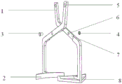
FIG. 1 is a schematic structural view of a drill sling according to the present invention.
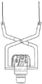
FIG. 2 is an exploded view of a drill sling according to the present invention
FIG. 3 is a schematic view of a drill sling according to the present invention;
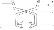
FIG. 4 is a schematic structural diagram of an embodiment of the present invention;
in the figure: 1. the clamping device comprises a clamping plate, 2 arc-shaped clamping plates, 3 bolts, 4 nuts, 5 penetrating holes, 6 matching holes, 7 matching grooves, 8 rib plates, 11 left clamping plates and 12 right clamping plates.
Detailed Description
The present invention will be further specifically described with reference to the following examples.
The first embodiment is as follows:
as shown in figure 4, the drill hoisting device comprises a left clamping plate 11, a right clamping plate 12, a bolt and a nut, wherein the left clamping plate and the right clamping plate are connected together through the bolt and the nut.
After adopting such structure, the left and right clamping plates are connected with the bolt and the nut to form a structure similar to scissors. When the through holes above the left clamping plate and the right clamping plate of the drill hoisting device penetrate through the steel wire rope and are hoisted upwards, the force of inward clamping is exerted between the left arc-shaped clamping plate and the right arc-shaped clamping plate at the lower parts of the left clamping plate and the right clamping plate. The left clamping plate and the right clamping plate of the hoisting device are aligned to the joint part of the drill bit, and the drill bit body is placed upwards, so that when the drill bit joint is clamped by the left clamping plate and the right clamping plate, the diameter of the drill bit body is larger than that of the drill bit joint, and when the drill bit hoisting device is lifted, the drill bit body can be firmly located between the left clamping plate and the right clamping plate under the action of the gravity of the drill bit. In other words, the drill lifting device has the advantages of simple structure, high clamping efficiency and high safety by means of the gravity action and the special scissor type clamping principle, and the efficient drill clamping efficiency is not directly related to the proficiency of workers, so that the drill lifting device can also have high lifting efficiency and high safety coefficient by adopting a conventional lifting method. Compared with the method adopting a full-intelligent hoisting device, the method can save the drilling cost and has low operation requirement on workers.
Example two:
referring to the attached drawings 1 to 3 in the specification, the drill bit hoisting device mainly comprises a clamping plate 1, an arc-shaped clamping plate 2, a bolt 3, a nut 4, a penetrating hole 5, a matching hole 6, a matching groove 7 and a rib plate 8, wherein the clamping plate 1, the rib plate 8 and the arc-shaped clamping plate 2 are fixedly connected together, and the arc-shaped clamping plate 2 is fixed at the bottom of the clamping plate 1. The clamping plate 1 is made of a Z-shaped stainless steel plate, and the clamping plate 1 is divided into a left clamping plate and a right clamping plate which have the same structural size and material. The matching hole 6 and the matching groove 7 are both arranged on the Z-shaped middle part of the clamping plate; two dress splint 1 pass through mating holes 6 about, link together at bolt 3 and nut 4, and about and two dress splint 1 can be round bolt 3 relative rotation, are equipped with cooperation recess 7 on the dress splint 1, about two dress splint 1 rotation range be the home range of cooperation recess 7.
The penetrating hole 5 is arranged at the tail end position of the clamping plate 1, and the hoisting steel wire rope penetrates through the penetrating hole 5 to hoist the drill bit.
Example three:
a drill hoisting device mainly comprises a clamping plate (1) and an arc-shaped clamping plate (2); the clamping plates (1) are Z-shaped, the clamping plates (1) are divided into a left clamping plate and a right clamping plate, and the left clamping plate and the right clamping plate (1) can rotate relatively; the arc-shaped clamping plate (2) is fixed at the bottom of the clamping plate (1).
The clamping plate is characterized in that a matching hole (6) is formed in the Z-shaped middle position of the clamping plate, the left clamping plate and the right clamping plate (1) are connected together through the matching hole (6) at a bolt (3) and a nut (4), and the left clamping plate and the right clamping plate (1) can rotate around the bolt (3).
And a matching groove (7) is formed in the Z-shaped middle position of the clamping plate, and the rotating ranges of the left clamping plate and the right clamping plate (1) are the moving ranges of the matching groove (7).
The clamping plate is characterized by further comprising a penetrating hole (5), and the penetrating hole (5) is arranged at the tail end of the clamping plate (1).
The arc-shaped splint (2) is also provided with a rib plate (8); the clamping plate (2) is fixedly connected with the rib plate (8) and the arc-shaped clamping plate (2).
The clamping plate (1) is made of a stainless steel plate.
The specific use method of the invention comprises the following steps:
firstly, the steel wire rope is penetrated through the penetrating holes 5 at the left side and the right side of the clamping plate, and then the steel wire rope is hooked and fixed by a large hook. Then remove drill bit hoist and mount ware to the drill bit top, the drill bit body is placed up, opens arc splint 2 about drill bit hoist and mount ware lower part respectively, when going to hang and transfer drill bit hoist and mount ware to about arc splint 2 just can clip the position that the drill bit connects, will control arc splint 2 and loosen, the tight drill bit of clamp that left and right splint can be nature under the effect of gravity connects. Like this when controlling splint 2 and pressing from both sides tight drill bit and connecting, because drill bit body diameter ratio drill bit connects greatly, when carrying drill bit hoisting machine, under the effect of drill bit self gravity, this can firmly be located between controlling the dress splint 2 of drill bit. After the drill bit is moved to a specified position, the left and right arc-shaped clamping plates 2 can be opened only by placing the drill bit for hoisting for a short distance, so that the drill bit is hoisted.
The working principle of the invention is as follows:
the drill lifting device has the advantages of simple structure, high clamping efficiency and high safety by depending on the gravity action and a special scissor type clamping principle, and the efficient drill clamping efficiency is not directly related to the proficiency of workers, so that the drill lifting device has high lifting efficiency and high safety coefficient by adopting a conventional lifting method. Compared with the method adopting a full-intelligent hoisting device, the method can save the drilling cost and has low operation requirement on workers.
The embodiments disclosed herein are to be considered in all respects as illustrative and not restrictive. The above-described embodiments may be omitted, replaced, or modified in various ways without departing from the scope of the appended claims and the gist thereof.
Claims (10)
1. A drill hoisting device is characterized in that: including two clamping plates, two clamping plate middle parts are crisscross articulated, two clamping plates are the centre gripping arm from the hinged end downwards, the centre gripping arm is C shape, the centre gripping arm end is provided with clamping part.
2. A drill sling, according to claim 1, characterised in that: the clamping part is two arc-shaped clamping plates which are arranged in a horizontal opposite mode.
3. A drill sling, according to claim 2, characterized in that: and a rib plate is arranged between the arc-shaped clamping plate and the clamping arm.
4. A drill sling, according to any one of claims 1 to 3, wherein: the clamping plate is a handle part upwards from the hinged end, and the handle part is arc-shaped.
5. A drill sling, according to claim 4, characterized in that: the handle is provided with a through hole.
6. A drill sling, according to claim 5, characterised in that: and the clamping surface of the arc-shaped clamping plate is provided with an anti-slip pad.
7. A drill sling, according to claim 5, characterised in that: and a magnetic non-slip mat is arranged on the clamping surface of the arc-shaped clamping plate.
8. A drill sling, according to claim 7, characterized in that: the magnetic anti-slip mat is a flexible magnetic strip.
9. A drill sling, according to claim 8, wherein: the middle sections of the two clamping plates are provided with matching grooves, and the matching grooves on the two clamping plates are oppositely and alternately arranged to limit the rotation range of the clamping plates.
10. A drill sling, according to any one of claims 1-3 or 4-9, wherein: the clamping plate is made of stainless steel.
Priority Applications (1)
| Application Number | Priority Date | Filing Date | Title |
|---|---|---|---|
| CN202010855939.1A CN114084791A (en) | 2020-08-24 | 2020-08-24 | Drill hoisting device |
Applications Claiming Priority (1)
| Application Number | Priority Date | Filing Date | Title |
|---|---|---|---|
| CN202010855939.1A CN114084791A (en) | 2020-08-24 | 2020-08-24 | Drill hoisting device |
Publications (1)
| Publication Number | Publication Date |
|---|---|
| CN114084791A true CN114084791A (en) | 2022-02-25 |
Family
ID=80295405
Family Applications (1)
| Application Number | Title | Priority Date | Filing Date |
|---|---|---|---|
| CN202010855939.1A Pending CN114084791A (en) | 2020-08-24 | 2020-08-24 | Drill hoisting device |
Country Status (1)
| Country | Link |
|---|---|
| CN (1) | CN114084791A (en) |
Cited By (1)
| Publication number | Priority date | Publication date | Assignee | Title |
|---|---|---|---|---|
| CN114835062A (en) * | 2022-07-04 | 2022-08-02 | 四川东泉机械设备制造有限公司 | Hydraulic climbing type lifting system |
Citations (5)
| Publication number | Priority date | Publication date | Assignee | Title |
|---|---|---|---|---|
| CN101657376A (en) * | 2007-02-22 | 2010-02-24 | 海雷廷·迪尔西兹 | Hoisting device |
| CN206645711U (en) * | 2017-03-09 | 2017-11-17 | 洛阳双瑞万基钛业有限公司 | A kind of drum lifting device |
| CN210236869U (en) * | 2019-07-15 | 2020-04-03 | 江西亚威电气有限公司 | Iron core lifting appliance |
| CN211198371U (en) * | 2019-12-02 | 2020-08-07 | 翟麦富 | Assembled building element hoist device |
| CN213802546U (en) * | 2020-08-24 | 2021-07-27 | 中石化石油工程技术服务有限公司 | Drill hoisting device |
-
2020
- 2020-08-24 CN CN202010855939.1A patent/CN114084791A/en active Pending
Patent Citations (5)
| Publication number | Priority date | Publication date | Assignee | Title |
|---|---|---|---|---|
| CN101657376A (en) * | 2007-02-22 | 2010-02-24 | 海雷廷·迪尔西兹 | Hoisting device |
| CN206645711U (en) * | 2017-03-09 | 2017-11-17 | 洛阳双瑞万基钛业有限公司 | A kind of drum lifting device |
| CN210236869U (en) * | 2019-07-15 | 2020-04-03 | 江西亚威电气有限公司 | Iron core lifting appliance |
| CN211198371U (en) * | 2019-12-02 | 2020-08-07 | 翟麦富 | Assembled building element hoist device |
| CN213802546U (en) * | 2020-08-24 | 2021-07-27 | 中石化石油工程技术服务有限公司 | Drill hoisting device |
Cited By (2)
| Publication number | Priority date | Publication date | Assignee | Title |
|---|---|---|---|---|
| CN114835062A (en) * | 2022-07-04 | 2022-08-02 | 四川东泉机械设备制造有限公司 | Hydraulic climbing type lifting system |
| CN114835062B (en) * | 2022-07-04 | 2022-09-13 | 四川东泉机械设备制造有限公司 | Hydraulic climbing type lifting system |
Similar Documents
| Publication | Publication Date | Title |
|---|---|---|
| CN107934750A (en) | Steel plate hoist | |
| CN107963548A (en) | Hoisting steel plate fixture | |
| CN209890088U (en) | Clamping claw for hoisting plate in engineering construction | |
| CN213802546U (en) | Drill hoisting device | |
| CN114084791A (en) | Drill hoisting device | |
| CN205527319U (en) | Anchor clamps are lifted by crane in shaped steel special use | |
| CN207483157U (en) | A kind of boom hoisting for large-scale workpiece | |
| CN205132903U (en) | Steel wire slings | |
| CN211393575U (en) | Multipurpose lifting appliance | |
| CN211169494U (en) | Prestress steel plate antiskid device | |
| CN213356693U (en) | Automatic lifting appliance for unpowered concrete pipe | |
| CN212769429U (en) | Fast assembling and disassembling clamp for concrete electric pole | |
| CN109795949B (en) | Lifting appliance used in engineering construction process | |
| CN210682959U (en) | A hang frock for well lid production | |
| CN220723289U (en) | Steel plate hoisting mechanism convenient for stable transportation | |
| CN221543827U (en) | Workpiece lifting sling | |
| CN218560825U (en) | Semicircular flange lifting appliance | |
| CN219058300U (en) | Lifting appliance with multi-claw lifting function | |
| CN220618140U (en) | Barreled chemical agent lifting appliance | |
| CN216945864U (en) | Become prefabricated tubular pile of size self-tightening formula hoist device | |
| CN215711127U (en) | Water mill rock drilling core gripping tool | |
| CN213415990U (en) | Lifting appliance for lifting nuclear power bent pipe | |
| CN217921073U (en) | Steel billet clamping and hoisting clamp | |
| CN218595905U (en) | Anchor clamps overhead hoist and equipment | |
| CN2530930Y (en) | Special self-locking sling grip for heavy store block |
Legal Events
| Date | Code | Title | Description |
|---|---|---|---|
| PB01 | Publication | ||
| PB01 | Publication | ||
| SE01 | Entry into force of request for substantive examination | ||
| SE01 | Entry into force of request for substantive examination |