CN114082848A - Mold and method for reducing width of bottom surface of deep drawing cylinder - Google Patents
Mold and method for reducing width of bottom surface of deep drawing cylinder Download PDFInfo
- Publication number
- CN114082848A CN114082848A CN202111394388.4A CN202111394388A CN114082848A CN 114082848 A CN114082848 A CN 114082848A CN 202111394388 A CN202111394388 A CN 202111394388A CN 114082848 A CN114082848 A CN 114082848A
- Authority
- CN
- China
- Prior art keywords
- plate
- die
- wedge
- movable block
- groove
- Prior art date
- Legal status (The legal status is an assumption and is not a legal conclusion. Google has not performed a legal analysis and makes no representation as to the accuracy of the status listed.)
- Pending
Links
Images


Classifications
-
- B—PERFORMING OPERATIONS; TRANSPORTING
- B21—MECHANICAL METAL-WORKING WITHOUT ESSENTIALLY REMOVING MATERIAL; PUNCHING METAL
- B21D—WORKING OR PROCESSING OF SHEET METAL OR METAL TUBES, RODS OR PROFILES WITHOUT ESSENTIALLY REMOVING MATERIAL; PUNCHING METAL
- B21D37/00—Tools as parts of machines covered by this subclass
- B21D37/10—Die sets; Pillar guides
-
- B—PERFORMING OPERATIONS; TRANSPORTING
- B21—MECHANICAL METAL-WORKING WITHOUT ESSENTIALLY REMOVING MATERIAL; PUNCHING METAL
- B21D—WORKING OR PROCESSING OF SHEET METAL OR METAL TUBES, RODS OR PROFILES WITHOUT ESSENTIALLY REMOVING MATERIAL; PUNCHING METAL
- B21D22/00—Shaping without cutting, by stamping, spinning, or deep-drawing
- B21D22/20—Deep-drawing
-
- B—PERFORMING OPERATIONS; TRANSPORTING
- B21—MECHANICAL METAL-WORKING WITHOUT ESSENTIALLY REMOVING MATERIAL; PUNCHING METAL
- B21D—WORKING OR PROCESSING OF SHEET METAL OR METAL TUBES, RODS OR PROFILES WITHOUT ESSENTIALLY REMOVING MATERIAL; PUNCHING METAL
- B21D45/00—Ejecting or stripping-off devices arranged in machines or tools dealt with in this subclass
- B21D45/02—Ejecting devices
- B21D45/04—Ejecting devices interrelated with motion of tool
Abstract
The invention discloses a die and a method for reducing the bottom surface width of a deep drawing cylinder, wherein a groove (8) is formed in the bottom surface of a concave die plate (3), a middle guide hole (9) and two side guide holes (10) are formed in the top surface of the concave die plate (3), the middle guide hole (9) and the two side guide holes (10) are both communicated with the groove (8), the middle guide hole (9) is arranged between the two side guide holes (10), a sliding chute (11) communicated with the groove (8) is formed in the top of a lower backing plate (2), a sliding block (12) is installed in the sliding chute (11) in a sliding mode, a horizontal spring (13) is fixedly arranged between the right side wall of the sliding block (12) and the right side wall of the sliding chute (11), and a left inclined plane (14) and a right inclined plane (15) are respectively arranged on the top surfaces of the left end portion and the right end portion of the sliding block (12). The beneficial effects of the invention are: the production efficiency of the finished product depth guide part is improved, the delivery period is shortened, the forming quality is improved, and the working strength of workers is reduced.
Description
Technical Field
The invention relates to the technical field of reducing the width of a bottom end surface of a cylinder body, in particular to a die and a method for reducing the width of the bottom surface of a deep drawing cylinder.
Background
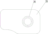
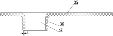
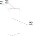
The structure of the drawing part processed by a certain progressive die is shown in figures 1-2, the drawing part comprises a plate body (35) and a cylinder body (36) integrally formed with the plate body, a through hole (37) in the cylinder body (36) penetrates through the plate body (35) to be arranged, the plane width of the bottom end face of the cylinder body (36) is H, and the numerical value of H is too large to meet the requirements of customers. In order to solve the problem, the depth-drawing part processed by the progressive die can only be processed secondarily, namely, the bottom of the inner wall of the through hole (37) is rounded manually to obtain a finished depth-drawing part with the bottom end surface plane width H, wherein the value of H is smaller than that of H, and the structure of the finished depth-drawing part is shown in figure 3. Although the forming method can meet the requirements of customers, the redundant rounding process is added, the production time is greatly increased, the delivery time is delayed, and the technical defect of low production efficiency exists. In addition, the size of the depth-drawing part is small, and the manual chamfering undoubtedly increases the working strength of workers. Therefore, a mold for improving the production efficiency of the finished deep drawing parts, shortening the delivery cycle, improving the molding quality and reducing the working strength of workers is needed.
Disclosure of Invention
The invention aims to overcome the defects of the prior art and provide a mould and a method for reducing the width of the bottom surface of a depth drawing cylinder, which have the advantages of compact structure, improvement on the production efficiency of finished depth drawing parts, shortening of delivery cycle, improvement on molding quality and reduction in the working strength of workers.
The purpose of the invention is realized by the following technical scheme: the utility model provides a mould of surface width at bottom of a section of thick bamboo is drawn in reduction, it includes mould and lower mould, the lower mould includes and sets firmly in base, lower bolster and the die board of an organic whole in order by down, go up the mould including from top to down set firmly in an organic whole pop-up, upper padding plate and fixed plate in order, the below of fixed plate is provided with and sets firmly in limiting plate and stripper of an organic whole in order, leaves the clearance between fixed plate and the limiting plate, and is connected with a plurality of extension spring, its characterized in that between fixed plate and the limiting plate: the bottom surface of the concave template is provided with a groove, the top surface of the concave template is provided with a middle guide hole and two side guide holes, the middle guide hole and the two side guide holes are communicated with the groove, the middle guide hole is arranged between the two side guide holes, the top of the lower backing plate is provided with a chute communicated with the groove, a sliding block is arranged in the chute in a sliding manner, a horizontal spring is fixedly arranged between the right side wall of the sliding block and the right side wall of the chute, the top surfaces of the left end part and the right end part of the sliding block are respectively provided with a left inclined surface and a right inclined surface, the concave template is provided with a drawing slot, the drawing slot is arranged right above the right inclined surface, the left inclined surface is provided with a U-shaped groove penetrating through the bottom surface of the sliding block, the base is internally provided with a lower spring, the top of the lower spring is fixedly provided with a lower force transmission column, the lower force transmission column upwards penetrates through the U-shaped groove and extends into the groove, and a movable block is fixedly arranged at the extending end, a wedge-shaped surface I matched with the left inclined surface is arranged on the bottom surface of the movable block, a top plate which is slidably installed in the groove is fixedly arranged at the top of the movable block, a lower convex die which is slidably installed in the middle guide hole is fixedly arranged at the top of the top plate, the lower convex die extends above the concave die plate, a circular boss is fixedly arranged at the extending end of the lower convex die, and an annular arc-shaped surface is formed between the circular boss and the lower convex die;
be provided with the last terrace die that sets firmly on the limiting plate in the stripper, the bottom and the extension of last terrace die downwardly extending stripper are served and are set firmly and lead positive post, lead positive post and set up directly over the round boss, be provided with two upper springs in the pop-up, the bottom of two upper springs all sets firmly the transmission post, and two upper force posts all run through upper padding plate, fixed plate, limiting plate and stripper setting in order, and two extension ends of going up the transmission post all lie in the below of leading positive post, and set up respectively directly over two side guide holes, the wedge pole has set firmly on the upper padding plate, the wedge pole run through fixed plate, limiting plate and stripper in order and extend and take out the slot, the bottom of wedge pole be provided with right inclined plane matched with wedge face II.
The lower backing plate is in threaded connection with the base through screws.
The material pressing insert is fixedly arranged in the discharging plate, and the upper convex die is arranged in the material pressing insert.
The diameter of the guide column is equal to the diameter of the through hole of the cylinder.
The diameter of the circular boss is smaller than that of the through hole of the cylinder.
The diameter of the middle guide hole is equal to the outer diameter of the cylinder.
The upper backing plate is fixed on the upper support through screws.
The method for reducing the width of the bottom surface of the deep drawing cylinder by the die comprises the following steps:
s1, fixedly connecting the upper support to a stamping head of a stamping die by a worker;
s2, sleeving the cylinder body of the semi-finished deepening part processed by the progressive die on the circular boss by a worker, and ensuring that the plate body of the semi-finished deepening part is positioned above the cylinder body;
s3, a worker controls a punching head of the punching die to move downwards, the punching head drives an upper die to move downwards, two upper force transmission columns penetrate through side guide holes downwards to be abutted against a top plate, the upper force transmission columns press the top plate downwards, the top plate drives a lower male die, a circular boss and a movable block to move downwards synchronously after being pressed, a barrel of a semi-finished deepening part enters a middle guide hole in the downward movement process, when the semi-finished deepening part is in a critical die closing state, a plate body of the semi-finished deepening part is abutted against a position between a discharging plate and a pressing insert, a wedge surface I of the movable block is contacted with a left inclined surface, and a wedge surface II of a wedge rod is contacted with a right inclined surface;
s4, with the continuous downward movement of the punching head, the upper support, the upper padding plate and the fixed plate move downward relative to the static discharging plate, the upper padding plate drives the wedge rod to move downward relative to the static discharging plate, the wedge surface II of the wedge rod abuts against the right inclined surface to push the sliding block to move leftward along the sliding groove, as the left inclined surface of the sliding block is matched with the wedge surface I of the movable block, the sliding block drives the movable block to move upward, the movable block drives the top plate to move upward, the top plate drives the lower male die and the circular boss to move upward synchronously, when the circular boss moves upward, the annular arc-shaped surface extrudes the bottom wall of the through hole of the barrel along the radial direction, when the circular boss is in a closed die state, namely, when the fixed plate is pressed on the limiting plate, a finished product depth-guiding part with the bottom end surface plane width being h can be formed;
s5, controlling the punch head to move upwards, driving the upper die to move upwards by the punch head, jacking the lower force transmission column upwards by the pressed lower spring in the resetting process of the upper die, jacking the movable block upwards by the lower force transmission column, jacking the top plate upwards by the movable block, jacking the lower male die and the circular boss upwards by the top plate, so that the finished product deepening part is jacked above the female die plate, and the finished product part can be taken away by a worker.
The invention has the following advantages: the production efficiency of the finished product deep drawing part is improved, the delivery period is shortened, the forming quality is improved, and the working strength of workers is reduced.
Drawings
FIG. 1 is a schematic structural diagram of a deep-drawing part machined by a conventional die-feed;
FIG. 2 is a bottom view of FIG. 1;
FIG. 3 is a schematic view of the structure of the finished deep drawing part;
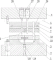
FIG. 4 is a schematic structural view of the present invention;
FIG. 5 is an enlarged view of a portion I of FIG. 4;
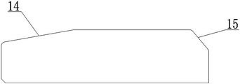
FIG. 6 is a schematic structural view of a slider;
FIG. 7 is a top view of FIG. 6;
FIG. 8 is a schematic view of the construction of the lower punch;
FIG. 9 is a schematic structural view of an upper male die;
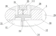
FIG. 10 is a schematic view of the present invention in a closed mold state;
FIG. 11 is an enlarged partial view of section II of FIG. 10;
FIG. 12 is an enlarged partial view of section III of FIG. 11;
in the figure, 1-base, 2-lower backing plate, 3-concave template, 4-upper support, 5-upper backing plate, 6-fixing plate, 7-extension spring, 8-groove, 9-middle guide hole, 10-side guide hole, 11-chute, 12-slide block, 13-horizontal spring, 14-left inclined plane, 15-right inclined plane, 16-drawing slot, 17-U-shaped slot, 18-lower spring, 19-lower force transmission column, 20-wedge surface I, 21-top plate, 22-lower convex mould, 23-round boss, 24-annular arc surface, 25-upper convex mould, 26-guide column, 27-upper spring, 28-upper force transmission column, 29-wedge rod, 30-wedge surface II, 31-pressing insert, 32-limiting plate, 33-stripper plate, 34-movable block, 35-plate body, 36-cylinder body and 37-through hole.
Detailed Description
The invention will be further described with reference to the accompanying drawings, without limiting the scope of the invention to the following:
as shown in fig. 4-9, a mould of deep section of thick bamboo bottom surface width is drawn in reduction, it includes mould and lower mould, the lower mould includes from bottom to top sets firmly in integrative base 1, lower bolster 2 and die board 3 in order, go up the mould including from top to bottom sets firmly in integrative pop-up 4, upper padding plate 5 and fixed plate 6 in order, the below of fixed plate 6 is provided with and sets firmly in integrative limiting plate 32 and stripper 33 in order, leaves the clearance between fixed plate 6 and the limiting plate 32, and is connected with a plurality of extension spring 7 between fixed plate 6 and the limiting plate 32: the bottom surface of the concave template 3 is provided with a groove 8, the top surface of the concave template 3 is provided with a middle guide hole 9 and two side guide holes 10, the middle guide hole 9 and the two side guide holes 10 are both communicated with the groove 8, the middle guide hole 9 is arranged between the two side guide holes 10, the top of the lower backing plate 2 is provided with a chute 11 communicated with the groove 8, a slide block 12 is arranged in the chute 11 in a sliding way, a horizontal spring 13 is fixedly arranged between the right side wall of the slide block 12 and the right side wall of the chute 11, the top surfaces of the left end part and the right end part of the slide block 12 are respectively provided with a left inclined surface 14 and a right inclined surface 15, the concave template 3 is provided with a drawing slot 16, the drawing slot 16 is arranged right above the right inclined surface 15, the left inclined surface 14 is provided with a U-shaped groove 17 penetrating through the bottom surface of the slide block 12, a lower spring 18 is arranged in the base 1, and the top of the lower spring 18 is fixedly provided with a lower force transmission column 19, lower force transmission post 19 upwards runs through U-shaped groove 17 and extends in recess 8, and extend and serve and set firmly movable block 34, be provided with on the basal surface of movable block 34 with left inclined plane 14 matched with wedge face I20, the top of movable block 34 has set firmly roof 21 of slidable mounting in recess 8, the top of roof 21 has set firmly lower punch 22 of slidable mounting in middle guiding hole 9, lower punch 22 extends and has set firmly round boss 23 on the top of die board 3 and the extension, the diameter of round boss 23 is less than the through-hole diameter of barrel, be formed with annular arcwall face 24 between round boss 23 and the lower punch 22.
An upper male die 25 fixedly arranged on a limit plate 32 is arranged in the discharge plate 33, the upper male die 25 extends downwards below the discharge plate 33, a guide column 26 is fixedly arranged on the extending end of the upper male die 25, the diameter of the guide column 26 is equal to that of a through hole of the cylinder body, the guide column 26 is arranged right above the circular boss 23, two upper springs 27 are arranged in the upper support 4, upper force transmission columns 28 are fixedly arranged at the bottoms of the two upper springs 27, the two upper force transmission columns 28 sequentially penetrate through the upper backing plate 5, the fixing plate 6, the limiting plate 32 and the discharging plate 33, the extending ends of the two upper force transmission columns 28 are positioned below the pilot column 26, and set up respectively directly over two side guiding holes 10, set firmly wedge rod 29 on the upper padding plate 5, wedge rod 29 runs through fixed plate 6, limiting plate 32 and stripper 33 in order and extends in taking out slot 16, and wedge rod 29's bottom is provided with and right inclined plane 15 matched with wedge face II 30.
The lower backing plate 2 is in threaded connection with the base 1 through screws. A material pressing insert 31 is fixedly arranged in the discharging plate 33, and the upper male die 25 is arranged in the material pressing insert 31. The diameter of the middle guide hole 9 is equal to the outer diameter of the cylinder 36, and the upper backing plate 5 is fixed on the upper support 4 through screws.
The method for reducing the width of the bottom surface of the deep drawing cylinder by the die comprises the following steps:
s1, fixedly connecting the upper support 4 to a stamping head of a stamping die by a worker;
s2, sleeving the cylinder 36 of the semi-finished deepening part processed by the progressive die on the circular boss 23 by a worker, and ensuring that the plate body 35 of the semi-finished deepening part is positioned above the cylinder 36;
s3, a worker controls a stamping head of the stamping die to move downwards, the stamping head drives an upper die to move downwards, two upper power columns 28 downwards penetrate through the side guide holes 10 to be abutted against a top plate 21, the upper power columns 28 downwards press the top plate 21, the top plate 21 drives a lower male die 22, a circular boss 23 and a movable block 34 to synchronously move downwards after being pressed, a cylinder 36 of a semi-finished product drawing part enters the middle guide hole 9 in the downward movement process, when the semi-finished product drawing part is in a critical die closing state, a plate body 35 of the semi-finished product drawing part is abutted against and pressed between a discharging plate 33 and a pressing insert 31, a wedge face I20 of the movable block 34 is in contact with the left inclined plane 14, and a wedge face II30 of a wedge rod 29 is in contact with the right inclined plane 15;
s4, as the punch head continues to move downwards, the upper support 4, the upper cushion plate 5 and the fixing plate 6 move downwards relative to the static discharging plate 33, the upper cushion plate 5 drives the wedge-shaped rod 29 to move downwards relative to the static discharging plate 33, the wedge-shaped surface II30 of the wedge-shaped rod 29 abuts against the right inclined surface 15, the slide block 12 is pushed to move leftwards along the slide groove 11, because the left inclined surface 14 of the slide block 12 is matched with the wedge-shaped surface I20 of the movable block 34, the slide block 12 drives the movable block 34 to move upwards, the movable block 34 drives the top plate 21 to move upwards, the top plate 21 drives the lower male die 22 and the circular boss 23 to synchronously move upwards, when the circular boss 23 moves upward, the annular arc-shaped surface 24 presses the bottom wall of the through hole 37 of the cylinder 36 radially outward, and when in the mold-closed state, as shown in fig. 10 to 12, namely, when the fixed plate 6 is pressed on the limit plate 32, a finished deepening part with the bottom end face plane width of h can be formed;
s5, controlling the punch to move upwards, driving the upper die to move upwards by the punch, when the upper die is reset, the pressed lower spring 18 jacks the lower force transmission column 19 upwards, the lower force transmission column 19 jacks the movable block 34 upwards, the movable block 34 jacks the top plate 21 upwards, the top plate 21 jacks the lower punch 22 and the circular boss 23 upwards, and therefore the finished product deepening part is jacked above the concave die plate 3, and the worker can take away the finished product part.
Therefore, in the whole forming process, the bottom of the inner wall of the through hole 37 of the cylinder 36 does not need to be rounded manually, so that the working strength of workers is greatly reduced, and the forming efficiency of products is improved. In addition, this mould has realized once only to the diapire chamfer of through-hole 37 to further improvement shaping efficiency, and then improved delivery cycle, still greatly improved the shaping quality of product simultaneously.
Finally, it should be noted that: although the present invention has been described in detail with reference to the foregoing embodiments, it will be apparent to those skilled in the art that changes may be made in the embodiments and/or equivalents thereof without departing from the spirit and scope of the invention. Any modification, equivalent replacement, or improvement made within the spirit and principle of the present invention should be included in the protection scope of the present invention.
Claims (8)
1. The utility model provides a mould of surface width at bottom of section of thick bamboo is drawn deeply in reduction, it includes mould and lower mould, the lower mould includes by down up set firmly in base (1) of an organic whole, lower bolster (2) and die board (3) in order, go up the mould including by last down set firmly in an organic whole pop-up (4), upper padding plate (5) and fixed plate (6) in order, the below of fixed plate (6) is provided with and sets firmly in limiting plate (32) and stripper (33) of an organic whole in order, leaves the clearance between fixed plate (6) and limiting plate (32), and is connected with a plurality of extension spring (7) between fixed plate (6) and limiting plate (32), its characterized in that: the bottom surface of the concave template (3) is provided with a groove (8), the top surface of the concave template (3) is provided with a middle guide hole (9) and two side guide holes (10), the middle guide hole (9) and the two side guide holes (10) are communicated with the groove (8), the middle guide hole (9) is arranged between the two side guide holes (10), the top of the lower backing plate (2) is provided with a sliding groove (11) communicated with the groove (8), the sliding groove (11) is internally provided with a sliding block (12), a horizontal spring (13) is fixedly arranged between the right side wall of the sliding block (12) and the right side wall of the sliding groove (11), the top surfaces of the left end part and the right end part of the sliding block (12) are respectively provided with a left inclined plane (14) and a right inclined plane (15), the concave template (3) is provided with a drawing slot (16), and the drawing slot (16) is arranged right above the right inclined plane (15), the left inclined surface (14) is provided with a U-shaped groove (17) which penetrates through the bottom surface of the sliding block (12), a lower spring (18) is arranged in the base (1), a lower force transmission column (19) is fixedly arranged at the top of the lower spring (18), the lower force transmission column (19) upwards penetrates through the U-shaped groove (17) and extends into the groove (8), a movable block (34) is fixedly arranged on the extending end, a wedge-shaped surface I (20) matched with the left inclined surface (14) is arranged on the bottom surface of the movable block (34), a top plate (21) slidably mounted in the groove (8) is fixedly arranged at the top of the movable block (34), a lower male die (22) slidably mounted in the middle guide hole (9) is fixedly arranged at the top of the top plate (21), the lower male die (22) extends above the concave die plate (3), a circular boss (23) is fixedly arranged on the extending end, and an annular arc-shaped surface (24) is formed between the circular boss (23) and the lower male die (22);
the improved structure is characterized in that an upper male die (25) fixedly arranged on a limiting plate (32) is arranged in the discharging plate (33), the upper male die (25) extends downwards to the lower part of the discharging plate (33) and is extended to be fixedly provided with a guide column (26), the guide column (26) is arranged right above a circular boss (23), two upper springs (27) are arranged in the upper support (4), an upper force column (28) is fixedly arranged at the bottom of each upper spring (27), the two upper force columns (28) sequentially penetrate through an upper backing plate (5), a fixing plate (6), the limiting plate (32) and the discharging plate (33), the extending ends of the two upper force columns (28) are respectively arranged right above two side guide holes (10), a wedge-shaped rod (29) is fixedly arranged on the upper backing plate (5), the wedge-shaped rod (29) penetrates through the fixing plate (6), the limiting plate (32) and the discharging plate (33) in sequence and extends into a slot (16), the bottom of the wedge-shaped rod (29) is provided with a wedge-shaped surface II (30) matched with the right inclined surface (15).
2. The mold for reducing the width of the bottom surface of a deep drawing cylinder according to claim 1, wherein: the lower backing plate (2) is in threaded connection with the base (1) through screws.
3. The mold for reducing the width of the bottom surface of a deep drawing cylinder according to claim 1, wherein: a material pressing insert (31) is fixedly arranged in the discharging plate (33), and the upper male die (25) is arranged in the material pressing insert (31).
4. The mold for reducing the width of the bottom surface of a deep drawing cylinder according to claim 1, wherein: the diameter of the guide column (26) is equal to the diameter of the through hole of the cylinder.
5. The mold for reducing the width of the bottom surface of a deep drawing cylinder according to claim 1, wherein: the diameter of the round boss (23) is smaller than that of the through hole of the cylinder.
6. The mold for reducing the width of the bottom surface of a deep drawing cylinder according to claim 1, wherein: the diameter of the middle guide hole (9) is equal to the outer diameter of the cylinder body (36).
7. The mold for reducing the width of the bottom surface of a deep drawing cylinder according to claim 1, wherein: the upper backing plate (5) is fixed on the upper support (4) through screws.
8. The method for reducing the width of the bottom surface of the deep drawing cylinder by using the die according to any one of claims 1 to 7, wherein the method comprises the following steps: it comprises the following steps:
s1, fixedly connecting the upper support (4) to a stamping head of a stamping die by a worker;
s2, sleeving the cylinder (36) of the semi-finished deepening part processed by the progressive die on the circular boss (23) by a worker, and ensuring that the plate body (35) of the semi-finished deepening part is positioned above the cylinder (36);
s3, a worker controls a punching head of the punching die to move downwards, the punching head drives an upper die to move downwards, two upper force columns (28) penetrate through side guide holes (10) downwards to be abutted against a top plate (21), the upper force columns (28) press the top plate (21) downwards, the top plate (21) is pressed to drive a lower male die (22), a circular boss (23) and a movable block (34) to move downwards synchronously, a cylinder body (36) of a semi-finished product drawing part enters a middle guide hole (9) in the downward movement process, when the semi-finished product drawing part is in a critical die closing state, a plate body (35) of the semi-finished product drawing part is abutted against and pressed between a discharging plate (33) and a pressing insert (31), a wedge surface I (20) of the movable block (34) is in contact with a left inclined surface (14), and a wedge surface II (30) of a wedge rod (29) is in contact with a right inclined surface (15);
s4, as the punching head continues to move downwards, the upper support (4), the upper backing plate (5) and the fixed plate (6) move downwards relative to the static discharging plate (33), the upper backing plate (5) drives the wedge rod (29) to move downwards relative to the static discharging plate (33), the wedge surface II (30) of the wedge rod (29) abuts against the right inclined surface (15) and then pushes the sliding block (12) to move leftwards along the sliding chute (11), because the left inclined surface (14) of the sliding block (12) is matched with the wedge surface I (20) of the movable block (34), the sliding block (12) drives the movable block (34) to move upwards, the movable block (34) drives the top plate (21) to move upwards, the top plate (21) drives the lower male die (22) and the circular boss (23) to move upwards synchronously, and when the circular boss (23) moves upwards, the annular arc-shaped surface (24) extrudes the bottom wall of the through hole (37) of the cylinder (36) outwards along the radial direction, when the die is in a die closing state, namely the fixing plate (6) is pressed on the limiting plate (32), a finished deepening part with the bottom end face plane width of h can be formed;
s5, controlling the punch head to move upwards, driving the upper die to move upwards by the punch head, when the upper die is in the resetting process, the lower compressed spring (18) jacks the lower force transmission column (19) upwards, the lower force transmission column (19) jacks the movable block (34) upwards, the movable block (34) jacks the top plate (21) upwards, the top plate (21) jacks the lower male die (22) and the circular boss (23) upwards, so that the finished product drawing part is pushed to the upper part of the female die plate (3), and the worker can take away the finished product part.
Priority Applications (1)
| Application Number | Priority Date | Filing Date | Title |
|---|---|---|---|
| CN202111394388.4A CN114082848A (en) | 2021-11-23 | 2021-11-23 | Mold and method for reducing width of bottom surface of deep drawing cylinder |
Applications Claiming Priority (1)
| Application Number | Priority Date | Filing Date | Title |
|---|---|---|---|
| CN202111394388.4A CN114082848A (en) | 2021-11-23 | 2021-11-23 | Mold and method for reducing width of bottom surface of deep drawing cylinder |
Publications (1)
| Publication Number | Publication Date |
|---|---|
| CN114082848A true CN114082848A (en) | 2022-02-25 |
Family
ID=80303194
Family Applications (1)
| Application Number | Title | Priority Date | Filing Date |
|---|---|---|---|
| CN202111394388.4A Pending CN114082848A (en) | 2021-11-23 | 2021-11-23 | Mold and method for reducing width of bottom surface of deep drawing cylinder |
Country Status (1)
| Country | Link |
|---|---|
| CN (1) | CN114082848A (en) |
Cited By (1)
| Publication number | Priority date | Publication date | Assignee | Title |
|---|---|---|---|---|
| CN116038820A (en) * | 2023-04-03 | 2023-05-02 | 成都宏明双新科技股份有限公司 | Efficient processing device and method for short strip production |
-
2021
- 2021-11-23 CN CN202111394388.4A patent/CN114082848A/en active Pending
Cited By (2)
| Publication number | Priority date | Publication date | Assignee | Title |
|---|---|---|---|---|
| CN116038820A (en) * | 2023-04-03 | 2023-05-02 | 成都宏明双新科技股份有限公司 | Efficient processing device and method for short strip production |
| CN116038820B (en) * | 2023-04-03 | 2023-06-13 | 成都宏明双新科技股份有限公司 | Efficient processing device and method for short strip production |
Similar Documents
| Publication | Publication Date | Title |
|---|---|---|
| CN104668416B (en) | Cold heading forming method for deep hole in head of bolt | |
| CN114082848A (en) | Mold and method for reducing width of bottom surface of deep drawing cylinder | |
| CN216501889U (en) | Mold for reducing width of bottom surface of deep drawing cylinder | |
| CN102218485A (en) | Productive technology of rope head taper sleeve for elevator | |
| CN115722586A (en) | Forming die and forming method for high-precision formed pole | |
| CN212144210U (en) | Sub vehicle frame hypoplastron stamping die before car | |
| CN109454167B (en) | Single-step forming die for integral wave-shaped sheet of clutch | |
| CN203764756U (en) | Guide pillar moving-out type three-in-one raising die with combination mode of upper die and lower die varied | |
| CN110153345B (en) | Processing system and processing method of iron art flower leaves | |
| CN112775342A (en) | Thin-wall product profiling and shaping integrated machining tool and method | |
| CN110538922A (en) | progressive die for multiple thinning drawing and reverse drawing | |
| CN206104697U (en) | Welding electrode cap stamping die for manufacturing | |
| CN216911797U (en) | Ejection mechanism of automobile drawing die | |
| CN214290414U (en) | Mould of drawing dark many circular convex hulls on taking long convex hull product | |
| CN220837559U (en) | Stamping die convenient to drawing of patterns | |
| CN219664966U (en) | Stamping die easy to demould | |
| CN220361879U (en) | Automatic blanking die for sheet metal parts | |
| CN219520297U (en) | Side wall oil tank port mold ejection mechanism | |
| CN216632246U (en) | Porous one shot forming equipment of oil tank end cover | |
| CN220295664U (en) | Novel stamping die | |
| CN214161127U (en) | Rivet terminal surface levelling mould in high-accuracy mould | |
| CN218224503U (en) | Special-shaped forging is with forging mould | |
| CN214235792U (en) | Novel side-push forming device for step circle wrapping | |
| CN214161130U (en) | Leveling die for end face of part with taper in high-precision die | |
| CN219130642U (en) | Thrust wheel secondary shaping forging device |
Legal Events
| Date | Code | Title | Description |
|---|---|---|---|
| PB01 | Publication | ||
| PB01 | Publication | ||
| SE01 | Entry into force of request for substantive examination | ||
| SE01 | Entry into force of request for substantive examination |