CN114066986A - Three-dimensional coordinate determination method and device, electronic equipment and storage medium - Google Patents
Three-dimensional coordinate determination method and device, electronic equipment and storage medium Download PDFInfo
- Publication number
- CN114066986A CN114066986A CN202210026388.7A CN202210026388A CN114066986A CN 114066986 A CN114066986 A CN 114066986A CN 202210026388 A CN202210026388 A CN 202210026388A CN 114066986 A CN114066986 A CN 114066986A
- Authority
- CN
- China
- Prior art keywords
- joint
- predicted
- scale factor
- dimensional coordinates
- key points
- Prior art date
- Legal status (The legal status is an assumption and is not a legal conclusion. Google has not performed a legal analysis and makes no representation as to the accuracy of the status listed.)
- Granted
Links
Images


Classifications
-
- G—PHYSICS
- G06—COMPUTING; CALCULATING OR COUNTING
- G06T—IMAGE DATA PROCESSING OR GENERATION, IN GENERAL
- G06T7/00—Image analysis
- G06T7/70—Determining position or orientation of objects or cameras
- G06T7/73—Determining position or orientation of objects or cameras using feature-based methods
- G06T7/75—Determining position or orientation of objects or cameras using feature-based methods involving models
-
- G—PHYSICS
- G06—COMPUTING; CALCULATING OR COUNTING
- G06N—COMPUTING ARRANGEMENTS BASED ON SPECIFIC COMPUTATIONAL MODELS
- G06N3/00—Computing arrangements based on biological models
- G06N3/02—Neural networks
- G06N3/04—Architecture, e.g. interconnection topology
- G06N3/045—Combinations of networks
-
- G—PHYSICS
- G06—COMPUTING; CALCULATING OR COUNTING
- G06N—COMPUTING ARRANGEMENTS BASED ON SPECIFIC COMPUTATIONAL MODELS
- G06N3/00—Computing arrangements based on biological models
- G06N3/02—Neural networks
- G06N3/08—Learning methods
-
- G—PHYSICS
- G06—COMPUTING; CALCULATING OR COUNTING
- G06T—IMAGE DATA PROCESSING OR GENERATION, IN GENERAL
- G06T7/00—Image analysis
- G06T7/80—Analysis of captured images to determine intrinsic or extrinsic camera parameters, i.e. camera calibration
-
- G—PHYSICS
- G06—COMPUTING; CALCULATING OR COUNTING
- G06T—IMAGE DATA PROCESSING OR GENERATION, IN GENERAL
- G06T2207/00—Indexing scheme for image analysis or image enhancement
- G06T2207/20—Special algorithmic details
- G06T2207/20081—Training; Learning
-
- G—PHYSICS
- G06—COMPUTING; CALCULATING OR COUNTING
- G06T—IMAGE DATA PROCESSING OR GENERATION, IN GENERAL
- G06T2207/00—Indexing scheme for image analysis or image enhancement
- G06T2207/20—Special algorithmic details
- G06T2207/20084—Artificial neural networks [ANN]
-
- G—PHYSICS
- G06—COMPUTING; CALCULATING OR COUNTING
- G06T—IMAGE DATA PROCESSING OR GENERATION, IN GENERAL
- G06T2207/00—Indexing scheme for image analysis or image enhancement
- G06T2207/30—Subject of image; Context of image processing
- G06T2207/30244—Camera pose
Abstract
The application provides a method and a device for determining three-dimensional coordinates, electronic equipment and a storage medium, wherein the method comprises the following steps: acquiring a joint image of a joint; determining first input information; calculating the middle three-dimensional coordinates of the joint key points; predicting to obtain a prediction scale factor by the first neural network model according to the first input information; calculating the predicted three-dimensional coordinates of the joint key points; calculating a first predicted joint length for the joint; calculating a first predicted joint length loss; determining second input information; predicting to obtain the variable quantity of the predicted scale factor by the second neural network model according to the second input information; determining a total scale factor; calculating to obtain a second predicted joint length loss according to the total scale factor, and judging whether an iteration end condition is reached; and if so, calculating the three-dimensional coordinates of the joint key points according to the total scale factor and the intermediate three-dimensional coordinates of the joint key points. The method and the device can determine the three-dimensional coordinates of the key points of the joint based on the joint image and the joint length.
Description
Technical Field
The present application relates to the field of artificial intelligence technologies, and in particular, to a method and an apparatus for determining three-dimensional coordinates, an electronic device, and a storage medium.
Background
With the rapid development of computer vision technology, the deep learning technology is more and more widely applied in the field of image processing. In the related art, although joint images of joints may be acquired by a camera or the like, coordinates of the joints in a three-dimensional space cannot be determined from the joint images. Therefore, how to reversely determine the coordinates of the key points of the joints in the three-dimensional space through the joint images of the joints is an urgent technical problem to be solved in the related art.
Disclosure of Invention
In view of the foregoing problems, embodiments of the present application provide a method and an apparatus for determining three-dimensional coordinates, an electronic device, and a storage medium, so as to improve the foregoing problems.
According to an aspect of an embodiment of the present application, there is provided a method for determining three-dimensional coordinates, including: acquiring a joint image of a joint; determining first input information according to two-dimensional coordinates of joint key points in the joint image, the actual joint length of the joint and the relative depth of the joint key points in the joint image; the first input information comprises intermediate three-dimensional coordinates of the joint key points; carrying out scale factor prediction by the first neural network model according to the first input information to obtain a predicted scale factor; calculating to obtain a predicted three-dimensional coordinate of the joint key point according to the predicted scale factor and the intermediate three-dimensional coordinate of the joint key point; calculating a first predicted joint length of the joint according to the predicted three-dimensional coordinates of the joint key points; calculating to obtain a first predicted joint length loss according to the first predicted joint length of the joint and the actual joint length of the joint; determining second input information according to the first predicted joint length loss and the first input information; predicting the variable quantity of the scale factor by a second neural network model according to the second input information to obtain the predicted variable quantity of the scale factor; adding the variable quantity of the prediction scale factor and the prediction scale factor to obtain a total scale factor; calculating to obtain a second predicted joint length loss of the joint according to the total scale factor; judging whether an iteration end condition is reached according to the second predicted joint length loss of the joint; and if the iteration ending condition is determined to be reached, calculating to obtain the three-dimensional coordinates of the joint key points according to the total scale factor and the intermediate three-dimensional coordinates of the joint key points.
According to an aspect of an embodiment of the present application, there is provided an apparatus for determining three-dimensional coordinates, including: the acquisition module is used for acquiring a joint image of the joint. The first input information determining module is used for determining first input information according to two-dimensional coordinates of joint key points in the joint image, the actual joint length of the joint and the relative depth of the joint key points in the joint image; the first input information includes intermediate three-dimensional coordinates of the joint keypoints. And the first prediction module is used for predicting the scale factor according to the first input information by the first neural network model to obtain a predicted scale factor. And the predicted three-dimensional coordinate calculation module is used for calculating to obtain the predicted three-dimensional coordinates of the joint key points according to the predicted scale factors and the intermediate three-dimensional coordinates of the joint key points. And the first predicted joint length calculating module is used for calculating the first predicted joint length of the joint according to the predicted three-dimensional coordinates of the joint key points. And the first prediction joint length loss calculation module is used for calculating to obtain first prediction joint length loss according to the first prediction joint length of the joint and the actual joint length of the joint. A second input information determination module to determine second input information based on the first predicted joint length loss and the first input information. And the second prediction module is used for predicting the variable quantity of the scale factor by the second neural network model according to the second input information to obtain the predicted variable quantity of the scale factor. And the total scale factor calculation module is used for adding the predicted scale factor and the predicted scale factor to obtain a total scale factor. And the second predicted joint length loss calculation module is used for calculating to obtain second predicted joint length loss of the joint according to the total scale factor. And the judging module is used for judging whether the iteration ending condition is reached according to the second predicted joint length loss of the joint. And the first processing module is used for calculating to obtain the three-dimensional coordinates of the joint key points according to the total scale factors and the intermediate three-dimensional coordinates of the joint key points if the iteration ending condition is determined to be reached.
In some embodiments, the determining of the three-dimensional coordinates further comprises: and the second processing module is used for taking the total scale factor as a predicted scale factor in the next iteration process if the iteration end condition is determined not to be met, and returning to execute the step of calculating the predicted three-dimensional coordinates of the joint key points according to the predicted scale factor and the intermediate three-dimensional coordinates of the joint key points.
In some embodiments, the determining module comprises: a determination unit to determine whether a second predicted joint length loss of the joint is less than a loss threshold. An iteration end condition determining unit, configured to determine that an iteration end condition is reached if a second predicted joint length loss of the joint is less than a loss threshold; if the second predicted joint length loss for the joint is not less than the loss threshold, determining that an iteration end condition has not been reached.
In some embodiments, the determining of the three-dimensional coordinates further comprises: and the prediction relative depth calculation module is used for calculating the prediction relative depth of the joint key points according to the prediction three-dimensional coordinates of the joint key points. And the relative depth loss calculation module is used for calculating the relative depth loss according to the predicted relative depth of the joint key points and the relative depth of the joint key points. An adding module for adding the relative depth loss to the second input information.
In some embodiments, the first input information determination module comprises: and the middle three-dimensional coordinate calculation unit is used for calculating the middle three-dimensional coordinate of the joint key point according to the two-dimensional coordinate of the joint key point in the joint image and the camera internal reference of the camera from which the joint image comes. And the relative depth calculating unit is used for calculating the relative depth of the joint key point in the joint image according to the depth information of each pixel in the joint image and the depth value of the joint key point in the joint image. A first input information determining unit configured to combine the middle three-dimensional coordinates of the joint key points, the actual joint length of the joint, and the relative depth of the joint key points in the joint image to obtain the first input information.
In some embodiments, the second input information determination module comprises: a second input information determination unit configured to combine the first predicted joint length loss and the first input information to obtain the second input information.
In some embodiments, the second input information determination module further comprises: and the preprocessing unit is used for preprocessing the first predicted joint length loss through a third neural network to obtain a preprocessed first predicted joint length loss. And the data combination unit is used for combining the preprocessed first predicted joint length loss and the first input information to obtain the second input information.
In some embodiments, the joint keypoints of the joint comprise a first joint keypoint indicative of one end of the joint and a second joint keypoint indicative of the other end of the joint. The first predicted joint length calculation module includes: and the Euclidean distance calculating unit is used for calculating the Euclidean distance between the first joint key point and the second joint key point according to the predicted three-dimensional coordinates of the first joint key point and the predicted three-dimensional coordinates of the second joint key point. A first predicted joint length determination unit configured to use the calculated euclidean distance as a first predicted joint length of the joint.
In some embodiments, the predicted three-dimensional coordinate calculation module comprises: and the predicted three-dimensional coordinate calculation unit is used for multiplying the predicted scale factor and the middle three-dimensional coordinate of the joint key point to obtain the predicted three-dimensional coordinate of the joint key point.
According to an aspect of an embodiment of the present application, there is provided an electronic device including: a processor; a memory having computer readable instructions stored thereon which, when executed by the processor, implement a method of determining three-dimensional coordinates as described above.
According to an aspect of embodiments of the present application, there is provided a computer-readable storage medium having stored thereon computer-readable instructions which, when executed by a processor, implement a method of determining three-dimensional coordinates as described above.
According to an aspect of embodiments of the present application, there is provided a computer program product comprising computer instructions which, when executed by a processor, implement the method of determining three-dimensional coordinates as described above.
In the scheme of the application, the scale factor is determined in two stages, namely after first input information is determined according to two-dimensional coordinates of the joint key points in the joint image, the scale factor is predicted according to the first input information by the first neural network to obtain a predicted scale factor, then the scale factor variation is iteratively predicted according to second input information by the second neural network to obtain a predicted scale factor variation, then the predicted scale factor and the predicted scale factor variation are added to obtain a total scale factor, the three-dimensional coordinates of the joint key points are determined according to the total scale factor, and the three-dimensional coordinates of the joint key points are determined in stages by utilizing the joint image and the joint length.
In addition, in the solution of the present application, the second input information includes a first predicted joint length loss, which is calculated based on the actual length of the joint and a first predicted joint length calculated based on the predicted scaling factor, so that, by using the feature that the joint length of the joint is not changed, the joint length is used as the supervision information for determining the scaling factor variation, thereby ensuring the accuracy of the determined predicted scaling factor variation and further ensuring the accuracy of the three-dimensional coordinates of the subsequently determined joint key points.
It is to be understood that both the foregoing general description and the following detailed description are exemplary and explanatory only and are not restrictive of the invention, as claimed.
Drawings
The accompanying drawings, which are incorporated in and constitute a part of this specification, illustrate embodiments consistent with the present application and together with the description, serve to explain the principles of the application. It is obvious that the drawings in the following description are only some embodiments of the application, and that for a person skilled in the art, other drawings can be derived from them without inventive effort.
Fig. 1 is a flowchart illustrating a method for determining three-dimensional coordinates according to an embodiment of the present application.
Fig. 2 is a flowchart illustrating specific steps of step 102 according to an embodiment of the present application.
Fig. 3 is a flowchart illustrating a specific step of step 111 according to an embodiment of the present application.
Fig. 4 is a schematic diagram illustrating a process for determining three-dimensional coordinates according to an embodiment of the present application.
Fig. 5 is a block diagram illustrating an apparatus for determining three-dimensional coordinates according to an embodiment of the present application.
FIG. 6 illustrates a schematic structural diagram of a computer system suitable for use in implementing the electronic device of an embodiment of the present application.
Detailed Description
Example embodiments will now be described more fully with reference to the accompanying drawings. Example embodiments may, however, be embodied in many different forms and should not be construed as limited to the examples set forth herein; rather, these embodiments are provided so that this disclosure will be thorough and complete, and will fully convey the concept of example embodiments to those skilled in the art.
Furthermore, the described features, structures, or characteristics may be combined in any suitable manner in one or more embodiments. In the following description, numerous specific details are provided to give a thorough understanding of embodiments of the application. One skilled in the relevant art will recognize, however, that the subject matter of the present application can be practiced without one or more of the specific details, or with other methods, components, devices, steps, and so forth. In other instances, well-known methods, devices, implementations, or operations have not been shown or described in detail to avoid obscuring aspects of the application.
The block diagrams shown in the figures are functional entities only and do not necessarily correspond to physically separate entities. I.e. these functional entities may be implemented in the form of software, or in one or more hardware modules or integrated circuits, or in different networks and/or processor means and/or microcontroller means.
The flow charts shown in the drawings are merely illustrative and do not necessarily include all of the contents and operations/steps, nor do they necessarily have to be performed in the order described. For example, some operations/steps may be decomposed, and some operations/steps may be combined or partially combined, so that the actual execution sequence may be changed according to the actual situation.
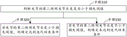
Fig. 1 is a flowchart illustrating a method for determining three-dimensional coordinates according to an embodiment of the present application, where the method of the present application may be performed by an electronic device with processing capability, such as a server, a cloud server, and the like, and is not limited in detail herein. As shown in fig. 1, the method includes:
step 101, acquiring a joint image of a joint.
In the present embodiment, the joint image may be a grayscale image (gray scale image) in which each pixel in the image may be represented by a luminance value (Intensity) of 0 (black) to 255 (white). Between 0 and 255 different grey levels are represented. In other embodiments, the joint image may also be an RGB image.
102, determining first input information according to two-dimensional coordinates of joint key points in a joint image, the actual joint length of a joint and the relative depth of the joint key points in the joint image; the first input information includes intermediate three-dimensional coordinates of the joint keypoints.
The joint key points refer to points on the joints having a joint identification function, and may be joint points, skeleton points, and the like, or may be other points customized by the user. It will be appreciated that for the same joint, a plurality of joint key points may be included thereon, and in the solution of the present application, since it relates to calculating the joint length of the joint, the joint key points in the present application include at least a first joint key point located at one end of the joint and a second joint key point located at the other end of the joint, and of course, in a specific embodiment, other joint key points besides the first joint key point and the second joint key point may be included.
For example, the joint key points may be: a point at the tip of a finger, a point at the phalanx base of the distal phalanx joint of a finger, a point at the end of the phalanx joint of a finger, a point at the metacarpophalangeal joint of an attachment point of a finger to a palm, a point at the wrist position of an attachment point of a palm to a forearm of a human body, and the like. The number and the position of the specific joint key points can be set according to actual needs, and are not particularly limited herein.
In some embodiments, a set of joint key points may be set for a joint in advance, so that, in step 102, the joint key points in the set of joint key points corresponding to the joint are located in the joint image. It is understood that the joint key points included in the set of joint key points are different for different joints.
The two-dimensional coordinates of the joint key points in the joint image refer to the coordinates of the joint key points in the image coordinate system of the joint image. Therefore, after the pixels where the key points of the joints are located in the joint images, the two-dimensional coordinates of the key points of the joints in the joint images can be correspondingly obtained.
In practice, there may be a problem of positioning error of the joint key points due to reasons such as unclear images, and in order to ensure accuracy of the three-dimensional coordinates of the subsequently determined joint key points, abnormal pixel points may be filtered first, and specifically, an isolated Forest algorithm (Isolation Forest) or a Local Outlier Factor (LOF) algorithm may be used to remove the abnormal pixel points.
The relative depth of the joint key point in the joint image refers to the depth value of a pixel where the joint key point is located relative to one or more pixel points in the joint image as reference pixel points.
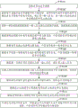
In some embodiments, as shown in FIG. 2, step 102 comprises:
and step 210, calculating to obtain a middle three-dimensional coordinate of the joint key point according to the two-dimensional coordinate of the joint key point in the joint image and the camera internal reference of the camera from which the joint image is derived.
The camera intrinsic parameters comprise the focal length of the camera and the coordinates of the optical center of the camera, the camera intrinsic parameter matrix is a matrix constructed according to the focal length of the camera and the coordinates of the optical center of the camera, the matrix is called as a camera intrinsic parameter matrix and is marked as K, and K is:

wherein Is the focal length of the camera and,
 are the coordinates of the optical center of the camera.
For a point P in the world coordinate system, the coordinates of the point P in the world coordinate system are assumed to be (X, Y, C), and in the camera coordinate system of the camera, the coordinates of the point P are assumed to be (X)C,YC,ZC) Based on the camera, the coordinates of the point P in the image coordinate system after perspective projection of the point P are (u, v), and the specific coordinate transformation process can be described by the following formula:

From the above, it can be obtained:

Further transformation yields:

If the point P is a key point of the joint in the present application, the coordinates are as described above The intermediate three-dimensional coordinates of the key points of the joint are considered,
 may be considered a scaling factor in the present application.
Specifically, in order to calculate the middle three-dimensional coordinate of the joint key point, one dimension is first supplemented to the two-dimensional coordinate of the joint key point to obtain the middle three-dimensional coordinate of the joint key point Then, the inverse matrix of the camera internal reference matrix is multiplied to obtain a middle three-dimensional coordinate which is recorded as
 :
:

Wherein Representing the inverse of the camera's camera reference matrix.
And step 220, calculating the relative depth of the joint key point in the joint image according to the depth information of each pixel in the joint image and the depth value of the joint key point in the joint image.
The depth information of each pixel in the joint image is used to indicate the depth value of the corresponding pixel in the joint image.
In some embodiments, in the process of image acquisition facing a joint, a joint image of the joint is acquired at the same time, and a depth image of the joint is acquired, where the value of each pixel point in the depth image is the depth value of the corresponding pixel point. Similarly, in order to determine the depth value corresponding to the joint key point, the joint key point is positioned in the depth image, so that the depth value of the joint key point is correspondingly obtained.
On the basis, after the depth value of each pixel is obtained, one pixel point is selected as a reference pixel point, and the relative depth of each joint key point in the joint image is correspondingly calculated. The reference pixel points may be pixel points with the minimum depth value in the joint image, or pixel points with the median depth value in the joint image, or other pixel points, and may be specifically set according to actual needs.
When the pixel point with the minimum depth value in the joint image is selected as the reference pixel point, the relative depth of the joint key point can be calculated according to the following formula (5):

In some embodiments, in order to perform dimension unification, and avoid that the range of the determined relative depth value is large due to a large difference between the depth values of the pixels in the joint image, the relative depth obtained by dividing the calculated relative depth according to the formula (5) may be divided by a difference between the maximum depth value and the minimum depth value in the joint image, and a quotient obtained by the division may be used as a final relative depth of the joint key point, that is, the relative depth of each joint key point is calculated according to the following formula (6):

Wherein, in the above formulas (5) and (6), relative depth of a key point of a joint in the joint image;
 depth values of key points of joints;
 is the minimum depth value in the joint image;
 the largest depth value in the joint image.
And step 230, combining the middle three-dimensional coordinates of the joint key points, the actual joint length of the joint and the relative depth of the joint key points in the joint image to obtain first input information.
In some embodiments, the intermediate three-dimensional coordinates of the joint key points, the actual joint length of the joint, and the relative depth of the joint key points in the joint image are stitched to obtain the first input information.
Referring to fig. 1, in step 103, the first neural network model performs scale factor prediction according to the first input information to obtain a predicted scale factor.
In the present application, the scale factor predicted by the first neural network for the joint key point is referred to as a predicted scale factor.
In some embodiments, the first neural network model may be constructed from a fully-connected network, which may include multiple fully-connected network layers, for example, if the first input information is a one-dimensional array, scale factor prediction may be performed by the fully-connected network constructed first neural network model, which may be four fully-connected network layers in a specific embodiment.
In other embodiments, the first neural network model may be further constructed by a convolutional neural network, and if the first input information is a two-dimensional array or a more-dimensional array, the scale factor prediction may be performed by the first neural network model constructed by the convolutional neural network.
In other embodiments, the first neural network model may be set as a neural network model of a multi-network structure, and parameters of different network structures are different, so that the variety of predictions made by the first neural network on the prediction scale factor can be improved by changing the network structure of the first neural network model.
Of course, in other embodiments, the first neural network model may also be constructed by other neural networks, and is not specifically limited herein.
As described above, for a joint key point in the world coordinate system, the middle three-dimensional coordinate of the joint key point may be determined through perspective transformation of the camera, and then the coordinate of the joint key point in the image is determined, or conversely, the middle three-dimensional coordinate of the joint key point may be reversely calculated according to the coordinate of the joint key point in the image and the scale factor, and the specific process may be described as follows:

Wherein the content of the first and second substances, is a scale factor, and is a function of,
 representing two-dimensional coordinates based on scale factors and joint key points
 A function of the intermediate three-dimensional coordinates is calculated,
 representing three-dimensional coordinates from joint key points
 Camera internal reference matrix of sum camera
 And calculating a function of the intermediate three-dimensional coordinates of the joint key points.
And 104, calculating to obtain the predicted three-dimensional coordinates of the joint key points according to the predicted scale factors and the intermediate three-dimensional coordinates of the joint key points.
The predicted three-dimensional coordinates of the joint key points are three-dimensional coordinates calculated according to the predicted scale factors and the intermediate three-dimensional coordinates of the joint key points.
In this embodiment, the specific method for calculating the predicted three-dimensional coordinates of the joint key points is as follows: and multiplying the predicted scale factor by the middle three-dimensional coordinate of the joint key point to obtain the predicted three-dimensional coordinate of the joint key point.
Specifically, the predicted three-dimensional coordinates of the joint key points are calculated according to the following formula:

Wherein the content of the first and second substances, predicting three-dimensional coordinates of key points of the joint;
 is a predictive scale factor;
 the intermediate three-dimensional coordinates.
And 105, calculating a first predicted joint length of the joint according to the predicted three-dimensional coordinates of the key points of the joint.
As described above, the joint key points of the joint include the first joint key point indicating one end portion of the joint and the second joint key point indicating the other end portion of the joint; according to the above process, the predicted three-dimensional coordinates of the first joint key point and the predicted three-dimensional coordinates of the second joint key point can be correspondingly determined. On the basis, the joint length can be calculated according to the following process: calculating the Euclidean distance between the first joint key point and the second joint key point according to the predicted three-dimensional coordinates of the first joint key point and the predicted three-dimensional coordinates of the second joint key point; the calculated euclidean distance is used as a first predicted joint length of the joint.
The calculation formula of the euclidean distance is as follows:

Wherein the predicted three-dimensional coordinates of the first joint key point are (ii) a The predicted three-dimensional coordinates of the second joint key points are
 ;
; Is the Euclidean distance between the first joint key point and the second joint key point.
And 106, calculating to obtain the first predicted joint length loss according to the first predicted joint length of the joint and the actual joint length of the joint.
In some embodiments, subtracting the actual joint length of the joint and the first predicted joint length yields a loss of joint length.
Step 107, determining second input information according to the first predicted joint length loss and the first input information.
In some embodiments, the first predicted joint length loss and the first input information may be combined to obtain the second input information.
And step 108, predicting the variable quantity of the scale factor by the second neural network model according to the second input information to obtain the predicted variable quantity of the scale factor.
In some embodiments, the second neural network model may be built from a fully connected network, which may include multiple fully connected network layers, and in particular embodiments, the second neural network model may be a four fully connected network layers.
In other embodiments, the second neural network model may also be constructed from a convolutional neural network. Of course, in other embodiments, the second neural network model may also be constructed by other neural networks, and is not specifically limited herein.
In some embodiments, the second neural network model may be set as a neural network model of a multi-network structure, parameters are different between different network structures, and values of the predicted scale factor variation amount may be enriched by setting the network structure of the second neural network model.
And step 109, adding the variable quantity of the prediction scale factor and the prediction scale factor to obtain a total scale factor.
A second predicted joint length loss for the joint is calculated from the aggregate scaling factor, step 110.
In some embodiments, step 110 comprises: calculating target three-dimensional coordinates of the joint key points according to the total scale factors; calculating a second predicted joint length of the joint according to the target three-dimensional coordinate; and subtracting the actual joint length of the joint from the second predicted joint length of the joint to obtain a second predicted joint length loss of the joint.
In a specific embodiment, the target three-dimensional coordinates of the joint key points can be calculated from the total scale factor and the two-dimensional coordinates of the joint key points according to formula (7), and the three-dimensional coordinates calculated from the total scale factor and the two-dimensional coordinates of the joint key points are referred to as the target three-dimensional coordinates of the joint key points in the present application.
After the target three-dimensional coordinates of the joint key points are calculated, as described above, the joint key points of the joint include a first joint key point indicating one end portion of the joint and a second joint key point indicating the other end portion of the joint; according to the process, the target three-dimensional coordinates of the first joint key point and the target three-dimensional coordinates of the second joint key point can be correspondingly determined. On this basis, the second predicted joint length for that joint may be calculated according to equation (9).
And subtracting the actual joint length of the joint from the second predicted joint length of the joint to obtain a second predicted joint length loss of the joint.
And step 111, judging whether the iteration end condition is reached according to the second predicted joint length loss of the joint.
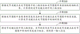
In some embodiments, as shown in fig. 3, step 111 comprises:
at step 310, it is determined whether the second predicted joint length for the joint is less than the loss threshold.
In step 111, it can be determined whether the iteration end condition is reached according to the process shown in fig. 3.
The loss threshold may be set according to actual needs, and is not particularly limited herein.
In step 320, if the second predicted joint length of the joint is less than the loss threshold, it is determined that an iteration end condition is reached.
In step 330, if the second predicted joint length of the joint is not less than the loss threshold, it is determined that the iteration end condition has not been reached.
Continuing to refer to fig. 1, in step 112, if it is determined that the iteration end condition is reached, the three-dimensional coordinates of the joint key points are calculated according to the total scale factor and the intermediate three-dimensional coordinates of the joint key points.
The three-dimensional coordinates of the joint key points refer to the coordinates of the joint key points in a world coordinate system. When it is determined that the iteration end condition is reached, the three-dimensional coordinates of the required joint key points may be calculated from the summed scale factors predicted by the second neural network model and the intermediate three-dimensional coordinates of the joint key points.
The formula used for calculating the three-dimensional coordinates of the joint key points is specifically as follows:

Wherein the content of the first and second substances, is a total scale factor.
In some embodiments, after step 111, the method further comprises: and if the iteration end condition is determined not to be reached, taking the total scale factor as a predicted scale factor in the next iteration process, and returning to execute the step 104.
When the iteration end condition is determined not to be met, the first neural network model and the second neural network model are required to be continuously utilized for prediction. When the next iteration is performed, the total scale factor in the previous iteration is used as the predicted scale factor in step 104, and step 104 and the subsequent steps are executed again according to the replaced predicted scale factor until the iteration end condition is determined to be reached from the joint length loss according to the retrieved second prediction. The previous round of predicted scale factors refers to the total scale factor obtained in the previous round of iteration process relative to the current round of iteration.
In the scheme of the application, the scale factor is determined in two stages, namely after first input information is determined according to two-dimensional coordinates of the joint key points in the joint image, the scale factor is predicted according to the first input information by the first neural network to obtain a predicted scale factor, then the scale factor variation is iteratively predicted according to second input information by the second neural network to obtain a predicted scale factor variation, then the predicted scale factor and the predicted scale factor variation are added to obtain a total scale factor, the three-dimensional coordinates of the joint key points are determined according to the total scale factor, and the three-dimensional coordinates of the joint key points are determined in stages by utilizing the joint image and the joint length.
In addition, in the solution of the present application, the second input information includes a first predicted joint length loss, which is calculated based on the actual length of the joint and a first predicted joint length calculated based on the predicted scaling factor, so that, by using the feature that the joint length of the joint is not changed, the joint length is used as the supervision information for determining the scaling factor variation, thereby ensuring the accuracy of the determined predicted scaling factor variation and further ensuring the accuracy of the three-dimensional coordinates of the subsequently determined joint key points.
Further, in the solution of the present application, under the condition that it is determined that the iteration end condition is not reached based on the total scale factor, the step 104 is executed again to predict the scale factor variation again without repeatedly predicting the scale factor. In practice, the scheme of the application is tested, and generally, the iteration is repeated three times to reach the iteration ending condition.
Further, the scheme of the application can be applied to an online application stage, and can also be applied to a training stage of the second neural network, and it can be understood that in the training stage, if it is determined that the iteration end condition is not met, parameters of the second neural network model also need to be adjusted, so that the scaling factor variation is predicted again according to new second input information through the second neural network after the parameters are adjusted, and therefore, the scheme of the application is wide in application range.
In some embodiments, after step 104, the method further comprises: calculating the predicted relative depth of the joint key points according to the predicted three-dimensional coordinates of the joint key points; calculating relative depth loss according to the predicted relative depth of the joint key points and the relative depth of the joint key points; a relative depth penalty is added to the second input information.
The predicted relative depth of the joint key point is the relative depth of the joint key point calculated from the predicted three-dimensional coordinates of the joint key. The predicted relative depth of the joint key point can be calculated according to formula (5) or formula (6), in the calculation process, the depth value corresponding to the three-dimensional coordinate of the joint key point is replaced by the depth value corresponding to the predicted three-dimensional coordinate of the joint key point, and the Z-axis coordinate value in the predicted three-dimensional coordinate of the joint key point is the corresponding depth value.
The predicted relative depth of the joint keypoints is subtracted from the relative depth of the joint keypoints calculated in step 220 to obtain the relative depth loss of the joint keypoints.
In this embodiment, the relative depth loss is also used as a data basis for the second neural network to predict the scale factor variation, so that more data are provided for predicting the scale factor variation, and the accuracy of predicting the scale factor variation can be improved.
In some embodiments, step 107 comprises: and preprocessing the first predicted joint length loss by using a third neural network to obtain the preprocessed first predicted joint length loss. And combining the preprocessed first predicted joint length loss with the first input information to obtain second input information.
In some embodiments, the third neural network may be constructed from a fully connected network, which may include multiple fully connected network layers. Of course, in other embodiments, the third neural network may also be other neural networks, and is not specifically limited herein.
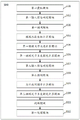
Fig. 4 is a schematic diagram illustrating a process of determining three-dimensional coordinates according to an embodiment of the present application, and as shown in fig. 4, a process of confirming three-dimensional coordinates of a key point of a joint is divided into two stages, i.e., a first stage and a second stage. In the first stage, a scale factor is predicted using a first neural network model. And in the second stage, the scale factor variation quantity is predicted by utilizing a second neural network model.
The first stage comprises the following specific processes: acquiring two-dimensional coordinates of joint key points in joint images Then according to two-dimensional coordinates of key points of the joints in the joint images
 And an inverse of a camera reference matrix of a camera from which the joint image originates
 Calculating intermediate three-dimensional coordinates of joint key points
 (ii) a Then, according to the depth information of each pixel point in the joint image and the depth value of the joint key point in the joint image, calculating to obtain the relative depth value of the joint key point
 Corresponding the key points of the joints to the actual joint lengths of the joints
 The middle three-dimensional coordinates of the key points of the joint
 And relative depth values of the joint key points
 Splicing and combining into first input information
 The first neural network model net1 is based on the first input information
 Performing scale factor prediction to predict scale factor
 。
。
The second stage process specifically comprises: according to a predicted scale factor And intermediate three-dimensional coordinates of joint key points
 Calculating key points of jointsPredicting three-dimensional coordinates
 Then according to the predicted three-dimensional coordinates of the key points of the joints
 Calculating a first predicted joint length for a joint
 (ii) a Will measure the actual length of the joint
 And the first predicted joint length
 Subtracting to obtain a first predicted joint length loss of the joint
 . Then predicting joint length loss based on the first
 And first input information
 Determining second input information
 From the second input information, the second neural network model net2
 And carrying out the variable quantity of the scale factor to obtain the variable quantity of the predicted scale factor.
In some embodiments, the first predicted joint length loss may be And the first input information
 And combining to obtain second input information.
In some embodiments, the predicted relative depth loss of the joint key point can be further calculated according to the predicted three-dimensional coordinates of the joint key point and the depth information of each pixel in the joint image Inputting the first input information
 First predicted joint length loss
 And predicted relative depth loss of the joint keypoints
 Splicing and combining into second input information
 。
。
And then, adding the predicted scale factor of the first stage and the predicted scale factor variation of the second stage to obtain a total scale factor. And then calculating a second predicted joint length loss of the joint according to the total scale factor, ending the iteration when the second predicted joint length loss of the joint is smaller than a loss threshold value, outputting the total scale factor of the last iteration, multiplying the total scale factor by the middle three-dimensional coordinate of the joint key point, and calculating the three-dimensional coordinate of the joint key point.
Embodiments of the apparatus of the present application are described below, which may be used to perform the methods of the above-described embodiments of the present application. For details which are not disclosed in the embodiments of the apparatus of the present application, reference is made to the above-described embodiments of the method of the present application.
Fig. 5 is a block diagram illustrating a three-dimensional coordinate determination apparatus according to an embodiment of the present application, and as shown in fig. 5, the three-dimensional coordinate determination apparatus 500 includes: a first obtaining module 501, configured to obtain a joint image of a joint. A first input information determining module 502, configured to determine first input information according to a two-dimensional coordinate of a joint key point in a joint image, an actual joint length of a joint, and a relative depth of the joint key point in the joint image; the first input information includes intermediate three-dimensional coordinates of the joint keypoints. The first prediction module 503 performs scale factor prediction by the first neural network model according to the first input information to obtain a predicted scale factor. And the predicted three-dimensional coordinate calculation module 504 is configured to calculate a predicted three-dimensional coordinate of the joint key point according to the predicted scale factor and the intermediate three-dimensional coordinate of the joint key point. And a first predicted joint length calculating module 505, configured to calculate a first predicted joint length of the joint according to the predicted three-dimensional coordinates of the joint key point. And a first predicted joint length loss calculation module 506, configured to calculate a first predicted joint length loss according to the first predicted joint length of the joint and the actual joint length of the joint. A second input information determining module 507 for determining second input information based on the first predicted joint length loss and the first input information. And a second prediction module 508, configured to perform, by the second neural network model, scale factor variation prediction according to the second input information, to obtain a predicted scale factor variation. And an aggregate scale factor calculation module 509, configured to add the predicted scale factor and the predicted scale factor to obtain an aggregate scale factor. A second predicted joint length loss calculation module 510 for calculating a second predicted joint length loss for the joint based on the aggregate scaling factor. And the judging module 511 is configured to judge whether the iteration end condition is reached according to the second predicted joint length loss of the joint. And the first processing module 512 is configured to calculate, if it is determined that the iteration end condition is reached, a three-dimensional coordinate of the joint key point according to the total scale factor and the intermediate three-dimensional coordinate of the joint key point.
In some embodiments, the apparatus 500 for determining three-dimensional coordinates further comprises: and the second processing module is used for taking the total scale factor as a predicted scale factor in the next iteration process if the iteration end condition is determined not to be reached, and returning to execute the step of calculating the predicted three-dimensional coordinates of the joint key points according to the predicted scale factor and the intermediate three-dimensional coordinates of the joint key points.
In some embodiments, the determining module 511 comprises: a determination unit for determining whether a second predicted joint length loss of the joint is less than a loss threshold. An iteration end condition determining unit, configured to determine that an iteration end condition is reached if a second predicted joint length loss of the joint is less than a loss threshold; if the second predicted joint length loss for the joint is not less than the loss threshold, then it is determined that the end-of-iteration condition has not been reached.
In some embodiments, the apparatus 500 for determining three-dimensional coordinates further comprises: and the prediction relative depth calculating module is used for calculating the prediction relative depth of the joint key points according to the prediction three-dimensional coordinates of the joint key points. And the relative depth loss calculation module is used for calculating the relative depth loss according to the predicted relative depth of the joint key points and the relative depth of the joint key points. An adding module for adding the relative depth loss to the second input information.
In some embodiments, the first input information determination module 502 includes: and the middle three-dimensional coordinate calculation unit is used for calculating the middle three-dimensional coordinate of the joint key point according to the two-dimensional coordinate of the joint key point in the joint image and the camera internal reference of the camera from which the joint image comes. And the relative depth calculating unit is used for calculating the relative depth of the joint key point in the joint image according to the depth information of each pixel in the joint image and the depth value of the joint key point in the joint image. And the first input information determining unit is used for combining the middle three-dimensional coordinates of the joint key points, the actual joint length of the joint and the relative depth of the joint key points in the joint image to obtain first input information.
In some embodiments, the second input information determination module 507 includes: and a second input information determination unit configured to combine the first predicted joint length loss and the first input information to obtain second input information.
In some embodiments, the second input information determination module 507 further comprises: and the preprocessing unit is used for preprocessing the first predicted joint length loss by the third neural network to obtain the preprocessed first predicted joint length loss. And the data combination unit is used for combining the preprocessed first predicted joint length loss and the first input information to obtain second input information.
In some embodiments, the joint keypoints of the joint comprise a first joint keypoint indicative of one end of the joint and a second joint keypoint indicative of the other end of the joint. The first predicted joint length calculation module 505 includes: and the Euclidean distance calculating unit is used for calculating the Euclidean distance between the first joint key point and the second joint key point according to the predicted three-dimensional coordinates of the first joint key point and the predicted three-dimensional coordinates of the second joint key point. A first predicted joint length determination unit configured to use the calculated euclidean distance as a first predicted joint length of the joint.
In some embodiments, the predicted three-dimensional coordinate calculation module 504 includes: and the predicted three-dimensional coordinate calculation unit is used for multiplying the predicted scale factor by the middle three-dimensional coordinate of the joint key point to obtain the predicted three-dimensional coordinate of the joint key point.
FIG. 6 illustrates a schematic structural diagram of a computer system suitable for use in implementing the electronic device of an embodiment of the present application. It should be noted that the computer system 600 of the electronic device shown in fig. 6 is only an example, and should not bring any limitation to the functions and the scope of use of the embodiments of the present application.
As shown in fig. 6, the computer system 600 includes a CPU601, which can perform various appropriate actions and processes, such as performing the methods in the above-described embodiments, according to a program stored in a ROM602 or a program loaded from a storage section 608 into a RAM 603. In the RAM603, various programs and data necessary for system operation are also stored. The CPU601, ROM602, and RAM603 are connected to each other via a bus 604. An I/O interface 605 is also connected to bus 604.
The following components are connected to the I/O interface 605: an input portion 606 including a keyboard, a mouse, and the like; an output section 607 including a Cathode Ray Tube (CRT), a Liquid Crystal Display (LCD), and the like, a speaker, and the like; a storage section 608 including a hard disk and the like; and a communication section 609 including a Network interface card such as a LAN (Local Area Network) card, a modem, or the like. The communication section 609 performs communication processing via a network such as the internet. The driver 610 is also connected to the I/O interface 605 as needed. A removable medium 611 such as a magnetic disk, an optical disk, a magneto-optical disk, a semiconductor memory, or the like is mounted on the drive 610 as necessary, so that a computer program read out therefrom is mounted in the storage section 608 as necessary.
In particular, according to embodiments of the application, the processes described above with reference to the flow diagrams may be implemented as computer software programs. For example, embodiments of the present application include a computer program product comprising a computer program embodied on a computer readable medium, the computer program comprising program code for performing the method illustrated by the flow chart. In such an embodiment, the computer program may be downloaded and installed from a network through the communication section 609, and/or installed from the removable medium 611. When the computer program is executed by the CPU601, various functions defined in the system of the present application are executed.
It should be noted that the computer readable medium shown in the embodiments of the present application may be a computer readable signal medium or a computer readable storage medium or any combination of the two. A computer readable storage medium may be, for example, but not limited to, an electronic, magnetic, optical, electromagnetic, infrared, or semiconductor system, apparatus, or device, or any combination of the foregoing. More specific examples of the computer readable storage medium may include, but are not limited to: an electrical connection having one or more wires, a portable computer diskette, a hard disk, a Random Access Memory (RAM), a Read-Only Memory (ROM), an Erasable Programmable Read-Only Memory (EPROM), a flash Memory, an optical fiber, a portable Compact Disc Read-Only Memory (CD-ROM), an optical storage device, a magnetic storage device, or any suitable combination of the foregoing. In the present application, a computer readable storage medium may be any tangible medium that can contain, or store a program for use by or in connection with an instruction execution system, apparatus, or device. In this application, however, a computer readable signal medium may include a propagated data signal with computer readable program code embodied therein, for example, in baseband or as part of a carrier wave. Such a propagated data signal may take many forms, including, but not limited to, electro-magnetic, optical, or any suitable combination thereof. A computer readable signal medium may also be any computer readable medium that is not a computer readable storage medium and that can communicate, propagate, or transport a program for use by or in connection with an instruction execution system, apparatus, or device. Program code embodied on a computer readable medium may be transmitted using any appropriate medium, including but not limited to: wireless, wired, etc., or any suitable combination of the foregoing.
The flowchart and block diagrams in the figures illustrate the architecture, functionality, and operation of possible implementations of systems, methods and computer program products according to various embodiments of the present application. Each block in the flowchart or block diagrams may represent a module, segment, or portion of code, which comprises one or more executable instructions for implementing the specified logical function(s). It should also be noted that, in some alternative implementations, the functions noted in the block may occur out of the order noted in the figures. For example, two blocks shown in succession may, in fact, be executed substantially concurrently, or the blocks may sometimes be executed in the reverse order, depending upon the functionality involved. It will also be noted that each block of the block diagrams or flowchart illustration, and combinations of blocks in the block diagrams or flowchart illustration, can be implemented by special purpose hardware-based systems which perform the specified functions or acts, or combinations of special purpose hardware and computer instructions.
The units described in the embodiments of the present application may be implemented by software, or may be implemented by hardware, and the described units may also be disposed in a processor. Wherein the names of the elements do not in some way constitute a limitation on the elements themselves.
As another aspect, the present application also provides a computer-readable storage medium, which may be contained in the electronic device described in the above embodiments; or may exist separately without being assembled into the electronic device. The computer readable storage medium carries computer readable instructions which, when executed by a processor, implement the method of any of the embodiments described above.
According to an aspect of the present application, there is also provided an electronic device, including: a processor; a memory having computer readable instructions stored thereon which, when executed by the processor, implement the method of any of the above embodiments.
According to an aspect of an embodiment of the present application, there is provided a computer program product or a computer program comprising computer instructions stored in a computer readable storage medium. The processor of the computer device reads the computer instructions from the computer-readable storage medium, and the processor executes the computer instructions to cause the computer device to perform the method of any of the above embodiments.
It should be noted that although in the above detailed description several modules or units of the device for action execution are mentioned, such a division is not mandatory. Indeed, the features and functionality of two or more modules or units described above may be embodied in one module or unit, according to embodiments of the application. Conversely, the features and functions of one module or unit described above may be further divided into embodiments by a plurality of modules or units.
Through the above description of the embodiments, those skilled in the art will readily understand that the exemplary embodiments described herein may be implemented by software, or by software in combination with necessary hardware. Therefore, the technical solution according to the embodiments of the present application can be embodied in the form of a software product, which can be stored in a non-volatile storage medium (which can be a CD-ROM, a usb disk, a removable hard disk, etc.) or on a network, and includes several instructions to enable a computing device (which can be a personal computer, a server, a touch terminal, or a network device, etc.) to execute the method according to the embodiments of the present application.
Other embodiments of the present application will be apparent to those skilled in the art from consideration of the specification and practice of the embodiments disclosed herein. This application is intended to cover any variations, uses, or adaptations of the invention following, in general, the principles of the application and including such departures from the present disclosure as come within known or customary practice within the art to which the invention pertains.
It will be understood that the present application is not limited to the precise arrangements described above and shown in the drawings and that various modifications and changes may be made without departing from the scope thereof. The scope of the application is limited only by the appended claims.
Claims (10)
1. A method for determining three-dimensional coordinates, the method comprising:
acquiring a joint image of a joint;
determining first input information according to two-dimensional coordinates of joint key points in the joint image, the actual joint length of the joint and the relative depth of the joint key points in the joint image; the first input information comprises intermediate three-dimensional coordinates of the joint key points;
carrying out scale factor prediction by the first neural network model according to the first input information to obtain a predicted scale factor;
calculating to obtain a predicted three-dimensional coordinate of the joint key point according to the predicted scale factor and the intermediate three-dimensional coordinate of the joint key point;
calculating a first predicted joint length of the joint according to the predicted three-dimensional coordinates of the joint key points;
calculating to obtain a first predicted joint length loss according to the first predicted joint length of the joint and the actual joint length of the joint;
determining second input information according to the first predicted joint length loss and the first input information;
predicting the variable quantity of the scale factor by a second neural network model according to the second input information to obtain the predicted variable quantity of the scale factor;
adding the variable quantity of the prediction scale factor and the prediction scale factor to obtain a total scale factor;
calculating to obtain a second predicted joint length loss of the joint according to the total scale factor;
judging whether an iteration end condition is reached according to the second predicted joint length loss of the joint;
and if the iteration ending condition is determined to be reached, calculating to obtain the three-dimensional coordinates of the joint key points according to the total scale factor and the intermediate three-dimensional coordinates of the joint key points.
2. The method of claim 1, wherein after determining whether an end-of-iteration condition is reached based on the second predicted length loss for the joint, the method further comprises:
and if the condition that the iteration is not finished is determined, taking the total scale factor as a predicted scale factor in the next iteration process, and returning to execute the step of calculating to obtain the predicted three-dimensional coordinates of the joint key points according to the predicted scale factor and the intermediate three-dimensional coordinates of the joint key points.
3. The method of claim 1 or 2, wherein said determining whether an end-of-iteration condition is reached based on a second predicted joint length loss for the joint comprises:
determining whether a second predicted joint length loss for the joint is less than a loss threshold;
determining that an iteration end condition is reached if a second predicted joint length loss for the joint is less than a loss threshold;
if the second predicted joint length loss for the joint is not less than the loss threshold, determining that an iteration end condition has not been reached.
4. The method of claim 1, wherein after calculating the predicted three-dimensional coordinates of the joint key points based on the predicted scaling factor and the intermediate three-dimensional coordinates of the joint key points, the method further comprises:
calculating the predicted relative depth of the joint key points according to the predicted three-dimensional coordinates of the joint key points;
calculating relative depth loss according to the predicted relative depth of the joint key points and the relative depth of the joint key points;
adding the relative depth loss to the second input information.
5. The method of claim 1, wherein determining first input information according to two-dimensional coordinates of joint key points in the joint image, actual joint lengths of the joints, and relative depths of the joint key points in the joint image comprises:
calculating to obtain a middle three-dimensional coordinate of the joint key point according to the two-dimensional coordinate of the joint key point in the joint image and camera internal parameters of a camera from which the joint image comes;
calculating the relative depth of the joint key point in the joint image according to the depth information of each pixel in the joint image and the depth value of the joint key point in the joint image;
and combining the middle three-dimensional coordinates of the joint key points, the actual joint length of the joint and the relative depth of the joint key points in the joint image to obtain the first input information.
6. The method of claim 1, wherein determining second input information based on the first predicted joint length loss and the first input information comprises:
preprocessing the first predicted joint length loss by a third neural network to obtain a preprocessed first predicted joint length loss;
and combining the preprocessed first predicted joint length loss with the first input information to obtain the second input information.
7. The method of claim 1, wherein the joint keypoints for the joint comprise a first joint keypoint indicative of one end of the joint and a second joint keypoint indicative of the other end of the joint;
calculating a first predicted joint length of the joint according to the predicted three-dimensional coordinates of the joint key points, including:
calculating the Euclidean distance between the first joint key point and the second joint key point according to the predicted three-dimensional coordinates of the first joint key point and the predicted three-dimensional coordinates of the second joint key point;
and taking the calculated Euclidean distance as a first predicted joint length of the joint.
8. An apparatus for determining three-dimensional coordinates, the apparatus comprising:
the acquisition module is used for acquiring a joint image of the joint;
the first input information determining module is used for determining first input information according to two-dimensional coordinates of joint key points in the joint image, the actual joint length of the joint and the relative depth of the joint key points in the joint image; the first input information comprises intermediate three-dimensional coordinates of the joint key points;
the first prediction module is used for predicting a scale factor by a first neural network model according to the first input information to obtain a predicted scale factor;
the predicted three-dimensional coordinate calculation module is used for calculating to obtain the predicted three-dimensional coordinate of the joint key point according to the predicted scale factor and the middle three-dimensional coordinate of the joint key point;
the first prediction joint length calculation module is used for calculating the first prediction joint length of the joint according to the prediction three-dimensional coordinates of the joint key points;
the first prediction joint length loss calculation module is used for calculating to obtain first prediction joint length loss according to the first prediction joint length of the joint and the actual joint length of the joint;
a second input information determination module for determining second input information based on the first predicted joint length loss and the first input information;
the second prediction module is used for predicting the variable quantity of the scale factor by the second neural network model according to the second input information to obtain the predicted variable quantity of the scale factor;
the total scale factor calculation module is used for adding the predicted scale factor and the predicted scale factor to obtain a total scale factor;
the second prediction joint length loss calculation module is used for calculating to obtain second prediction joint length loss of the joint according to the total scale factor;
the judging module is used for judging whether an iteration ending condition is reached according to the second prediction joint length loss of the joint;
and the first processing module is used for calculating to obtain the three-dimensional coordinates of the joint key points according to the total scale factors and the intermediate three-dimensional coordinates of the joint key points if the iteration ending condition is determined to be reached.
9. An electronic device, characterized in that the electronic device comprises:
one or more processors;
a memory electrically connected with the one or more processors;
one or more applications, wherein the one or more applications are stored in the memory and configured to be executed by the one or more processors, the one or more applications configured to perform the method of any of claims 1-7.
10. A computer-readable storage medium, having stored thereon program code that can be invoked by a processor to perform the method according to any one of claims 1 to 7.
Priority Applications (1)
| Application Number | Priority Date | Filing Date | Title |
|---|---|---|---|
| CN202210026388.7A CN114066986B (en) | 2022-01-11 | 2022-01-11 | Three-dimensional coordinate determination method and device, electronic equipment and storage medium |
Applications Claiming Priority (1)
| Application Number | Priority Date | Filing Date | Title |
|---|---|---|---|
| CN202210026388.7A CN114066986B (en) | 2022-01-11 | 2022-01-11 | Three-dimensional coordinate determination method and device, electronic equipment and storage medium |
Publications (2)
| Publication Number | Publication Date |
|---|---|
| CN114066986A true CN114066986A (en) | 2022-02-18 |
| CN114066986B CN114066986B (en) | 2022-04-19 |
Family
ID=80230973
Family Applications (1)
| Application Number | Title | Priority Date | Filing Date |
|---|---|---|---|
| CN202210026388.7A Active CN114066986B (en) | 2022-01-11 | 2022-01-11 | Three-dimensional coordinate determination method and device, electronic equipment and storage medium |
Country Status (1)
| Country | Link |
|---|---|
| CN (1) | CN114066986B (en) |
Cited By (1)
| Publication number | Priority date | Publication date | Assignee | Title |
|---|---|---|---|---|
| CN115018918A (en) * | 2022-08-04 | 2022-09-06 | 南昌虚拟现实研究院股份有限公司 | Three-dimensional coordinate determination method and device, electronic equipment and storage medium |
Citations (13)
| Publication number | Priority date | Publication date | Assignee | Title |
|---|---|---|---|---|
| CN110991319A (en) * | 2019-11-29 | 2020-04-10 | 广州市百果园信息技术有限公司 | Hand key point detection method, gesture recognition method and related device |
| CN111079570A (en) * | 2019-11-29 | 2020-04-28 | 北京奇艺世纪科技有限公司 | Human body key point identification method and device and electronic equipment |
| CN111160375A (en) * | 2019-12-31 | 2020-05-15 | 北京奇艺世纪科技有限公司 | Three-dimensional key point prediction and deep learning model training method, device and equipment |
| CN111401151A (en) * | 2020-02-28 | 2020-07-10 | 中国科学技术大学 | Accurate three-dimensional hand posture estimation method |
| CN111815754A (en) * | 2019-04-12 | 2020-10-23 | Oppo广东移动通信有限公司 | Three-dimensional information determination method, three-dimensional information determination device and terminal equipment |
| WO2021002025A1 (en) * | 2019-07-04 | 2021-01-07 | 富士通株式会社 | Skeleton recognition method, skeleton recognition program, skeleton recognition system, learning method, learning program, and learning device |
| CN112233222A (en) * | 2020-09-29 | 2021-01-15 | 深圳市易尚展示股份有限公司 | Human body parametric three-dimensional model deformation method based on neural network joint point estimation |
| CN112489102A (en) * | 2020-11-30 | 2021-03-12 | 北京百度网讯科技有限公司 | Three-dimensional reconstruction method, device, equipment and storage medium |
| CN112767489A (en) * | 2021-01-29 | 2021-05-07 | 北京达佳互联信息技术有限公司 | Three-dimensional pose determination method and device, electronic equipment and storage medium |
| CN112837362A (en) * | 2021-01-28 | 2021-05-25 | 清华大学深圳国际研究生院 | Three-dimensional human body posture estimation method for obtaining space positioning and computer readable storage medium |
| CN112836618A (en) * | 2021-01-28 | 2021-05-25 | 清华大学深圳国际研究生院 | Three-dimensional human body posture estimation method and computer readable storage medium |
| CN112989947A (en) * | 2021-02-08 | 2021-06-18 | 上海依图网络科技有限公司 | Method and device for estimating three-dimensional coordinates of human body key points |
| US20210398351A1 (en) * | 2020-06-22 | 2021-12-23 | Ariel Al, Inc. | 3d object model reconstruction from 2d images |
-
2022
- 2022-01-11 CN CN202210026388.7A patent/CN114066986B/en active Active
Patent Citations (13)
| Publication number | Priority date | Publication date | Assignee | Title |
|---|---|---|---|---|
| CN111815754A (en) * | 2019-04-12 | 2020-10-23 | Oppo广东移动通信有限公司 | Three-dimensional information determination method, three-dimensional information determination device and terminal equipment |
| WO2021002025A1 (en) * | 2019-07-04 | 2021-01-07 | 富士通株式会社 | Skeleton recognition method, skeleton recognition program, skeleton recognition system, learning method, learning program, and learning device |
| CN111079570A (en) * | 2019-11-29 | 2020-04-28 | 北京奇艺世纪科技有限公司 | Human body key point identification method and device and electronic equipment |
| CN110991319A (en) * | 2019-11-29 | 2020-04-10 | 广州市百果园信息技术有限公司 | Hand key point detection method, gesture recognition method and related device |
| CN111160375A (en) * | 2019-12-31 | 2020-05-15 | 北京奇艺世纪科技有限公司 | Three-dimensional key point prediction and deep learning model training method, device and equipment |
| CN111401151A (en) * | 2020-02-28 | 2020-07-10 | 中国科学技术大学 | Accurate three-dimensional hand posture estimation method |
| US20210398351A1 (en) * | 2020-06-22 | 2021-12-23 | Ariel Al, Inc. | 3d object model reconstruction from 2d images |
| CN112233222A (en) * | 2020-09-29 | 2021-01-15 | 深圳市易尚展示股份有限公司 | Human body parametric three-dimensional model deformation method based on neural network joint point estimation |
| CN112489102A (en) * | 2020-11-30 | 2021-03-12 | 北京百度网讯科技有限公司 | Three-dimensional reconstruction method, device, equipment and storage medium |
| CN112837362A (en) * | 2021-01-28 | 2021-05-25 | 清华大学深圳国际研究生院 | Three-dimensional human body posture estimation method for obtaining space positioning and computer readable storage medium |
| CN112836618A (en) * | 2021-01-28 | 2021-05-25 | 清华大学深圳国际研究生院 | Three-dimensional human body posture estimation method and computer readable storage medium |
| CN112767489A (en) * | 2021-01-29 | 2021-05-07 | 北京达佳互联信息技术有限公司 | Three-dimensional pose determination method and device, electronic equipment and storage medium |
| CN112989947A (en) * | 2021-02-08 | 2021-06-18 | 上海依图网络科技有限公司 | Method and device for estimating three-dimensional coordinates of human body key points |
Non-Patent Citations (6)
| Title |
|---|
| MUHAMMED KOCABAS等: ""Self-supervised learning of 3d human pose using multi-view geometry"", 《2019 IEEE/CVF CONFERENCE ON COMPUTER VISION AND PATTERN RECOGNITION (CVPR)》 * |
| QING YOU等: ""3D Human Motion Capture Based on Neural Network and Triangular Gaussian Point Cloud"", 《2020 39TH CHINESE CONTROL CONFERENCE (CCC)》 * |
| 刘阳温: ""AODPose基于弱监督对抗式相对深度约束的三维人体姿态估计"", 《中国优秀硕士学位论文全文数据库 信息科技辑》 * |
| 唐振华: ""基于深度学习的单目图像三维人体姿态估计算法研究"", 《中国优秀硕士学位论文全文数据库 信息科技辑》 * |
| 夏寅皓: ""基于单张RGB图像的手部三维重建"", 《中国优秀硕士学位论文全文数据库 信息科技辑》 * |
| 李唯嘉: ""基于人体动力学的三维人体姿态估计"", 《中国优秀硕士学位论文全文数据库 信息科技辑》 * |
Cited By (2)
| Publication number | Priority date | Publication date | Assignee | Title |
|---|---|---|---|---|
| CN115018918A (en) * | 2022-08-04 | 2022-09-06 | 南昌虚拟现实研究院股份有限公司 | Three-dimensional coordinate determination method and device, electronic equipment and storage medium |
| CN115018918B (en) * | 2022-08-04 | 2022-11-04 | 南昌虚拟现实研究院股份有限公司 | Three-dimensional coordinate determination method and device, electronic equipment and storage medium |
Also Published As
| Publication number | Publication date |
|---|---|
| CN114066986B (en) | 2022-04-19 |
Similar Documents
| Publication | Publication Date | Title |
|---|---|---|
| CN109508681A (en) | The method and apparatus for generating human body critical point detection model | |
| CN114186632B (en) | Method, device, equipment and storage medium for training key point detection model | |
| WO2019227716A1 (en) | Method for generating influenza prediction model, apparatus, and computer readable storage medium | |
| US11270519B2 (en) | Method of processing point cloud data based on neural network | |
| CN113159143A (en) | Infrared and visible light image fusion method and device based on jump connection convolution layer | |
| CN113065997B (en) | Image processing method, neural network training method and related equipment | |
| EP4318313A1 (en) | Data processing method, training method for neural network model, and apparatus | |
| CN114066986B (en) | Three-dimensional coordinate determination method and device, electronic equipment and storage medium | |
| CN114641799A (en) | Object detection device, method and system | |
| JP2019175321A (en) | Image evaluation device, image evaluation method, and computer program | |
| CN111539349A (en) | Training method and device of gesture recognition model, gesture recognition method and device thereof | |
| CN114550203A (en) | Method for determining three-dimensional coordinates of joint key points and related equipment | |
| CN109615620A (en) | The recognition methods of compression of images degree, device, equipment and computer readable storage medium | |
| CN116309983B (en) | Training method and generating method and device of virtual character model and electronic equipment | |
| CN110956131A (en) | Single-target tracking method, device and system | |
| CN111368668A (en) | Three-dimensional hand recognition method and device, electronic equipment and storage medium | |
| CN116894911A (en) | Three-dimensional reconstruction method, three-dimensional reconstruction device, electronic equipment and readable storage medium | |
| CN115311430A (en) | Training method and system of human body reconstruction model and computer equipment | |
| CN106803056B (en) | Estimation method and device of limb relationship | |
| CN114254724A (en) | Data processing method, neural network training method and related equipment | |
| CN115018918B (en) | Three-dimensional coordinate determination method and device, electronic equipment and storage medium | |
| CN115345937A (en) | Three-dimensional coordinate determination method and device, electronic equipment and storage medium | |
| CN116129206B (en) | Processing method and device for image decoupling characterization learning and electronic equipment | |
| CN112115900B (en) | Image processing method, device, equipment and storage medium | |
| CN112686936B (en) | Image depth completion method, apparatus, computer device, medium, and program product |
Legal Events
| Date | Code | Title | Description |
|---|---|---|---|
| PB01 | Publication | ||
| PB01 | Publication | ||
| SE01 | Entry into force of request for substantive examination | ||
| SE01 | Entry into force of request for substantive examination | ||
| GR01 | Patent grant | ||
| GR01 | Patent grant |