CN114050460A - Carbon brush structure of fan motor - Google Patents
Carbon brush structure of fan motor Download PDFInfo
- Publication number
- CN114050460A CN114050460A CN202210032003.8A CN202210032003A CN114050460A CN 114050460 A CN114050460 A CN 114050460A CN 202210032003 A CN202210032003 A CN 202210032003A CN 114050460 A CN114050460 A CN 114050460A
- Authority
- CN
- China
- Prior art keywords
- conductive
- cylinder
- carbon brush
- box
- fan motor
- Prior art date
- Legal status (The legal status is an assumption and is not a legal conclusion. Google has not performed a legal analysis and makes no representation as to the accuracy of the status listed.)
- Granted
Links
Images


Classifications
-
- H—ELECTRICITY
- H01—ELECTRIC ELEMENTS
- H01R—ELECTRICALLY-CONDUCTIVE CONNECTIONS; STRUCTURAL ASSOCIATIONS OF A PLURALITY OF MUTUALLY-INSULATED ELECTRICAL CONNECTING ELEMENTS; COUPLING DEVICES; CURRENT COLLECTORS
- H01R39/00—Rotary current collectors, distributors or interrupters
- H01R39/02—Details for dynamo electric machines
- H01R39/18—Contacts for co-operation with commutator or slip-ring, e.g. contact brush
- H01R39/28—Roller contacts; Ball contacts
-
- H—ELECTRICITY
- H01—ELECTRIC ELEMENTS
- H01R—ELECTRICALLY-CONDUCTIVE CONNECTIONS; STRUCTURAL ASSOCIATIONS OF A PLURALITY OF MUTUALLY-INSULATED ELECTRICAL CONNECTING ELEMENTS; COUPLING DEVICES; CURRENT COLLECTORS
- H01R39/00—Rotary current collectors, distributors or interrupters
- H01R39/02—Details for dynamo electric machines
- H01R39/36—Connections of cable or wire to brush
-
- H—ELECTRICITY
- H01—ELECTRIC ELEMENTS
- H01R—ELECTRICALLY-CONDUCTIVE CONNECTIONS; STRUCTURAL ASSOCIATIONS OF A PLURALITY OF MUTUALLY-INSULATED ELECTRICAL CONNECTING ELEMENTS; COUPLING DEVICES; CURRENT COLLECTORS
- H01R39/00—Rotary current collectors, distributors or interrupters
- H01R39/02—Details for dynamo electric machines
- H01R39/38—Brush holders
- H01R39/41—Brush holders cartridge type
- H01R39/415—Brush holders cartridge type with self-recoiling spring
-
- H—ELECTRICITY
- H02—GENERATION; CONVERSION OR DISTRIBUTION OF ELECTRIC POWER
- H02K—DYNAMO-ELECTRIC MACHINES
- H02K13/00—Structural associations of current collectors with motors or generators, e.g. brush mounting plates or connections to windings; Disposition of current collectors in motors or generators; Arrangements for improving commutation
- H02K13/003—Structural associations of slip-rings
Abstract
The invention discloses a carbon brush structure of a fan motor, which comprises a mounting rack, wherein a conductive core column is rotatably connected to the side surface of the mounting rack, one end of the conductive core column penetrates through the mounting rack, a conductive assembly is arranged at one end of the conductive core column penetrating through the mounting rack, a conductive carbon wheel is fixedly sleeved on the outer edge of the conductive core column, an inserting block is fixedly connected to the side surface of the mounting rack, an inserting barrel is movably sleeved on the outer edge of the inserting block, and the inserting block is connected with the inserting barrel through an elastic connecting piece. The invention replaces the traditional carbon brush structure, changes the sliding friction between the carbon brush and the collecting ring into rolling friction, greatly reduces the loss generated in the use process of the conductive carbon wheel, not only can lighten the economic burden of a user, but also can provide convenience for the use of a fan for assembling the motor, can also avoid the occurrence of the condition that the carbon powder is scattered in the motor and causes the short circuit of the motor, plays a role in protecting the motor and improves the stability of the motor during working.
Description
Technical Field
The invention relates to the technical field of motor carbon brushes, in particular to a fan motor carbon brush structure.
Background
The carbon brush of the motor is a general name of the carbon brush of the motor and the carbon brush of the generator, the carbon brush of the motor is a little like a rubber strip for wiping a pencil, a lead is led out from the top of the carbon brush, the size of the carbon brush is small, and the carbon brush in the prior art generally has the following two defects in the use process:
1. the carbon brush is mainly composed of carbon and is easy to wear in the using process, and sliding friction is usually adopted between the carbon brush and the collecting ring in the prior art, so that the friction force of interaction between the carbon brush and the rotor is large, the loss rate of the carbon brush is high, a user needs to replace the carbon brush of the fan motor regularly, the operating cost of the fan is increased, and troubles are brought to the using process of the user;
2. when the carbon brush works, the carbon brush is in contact with a collecting ring rotating by a generator to transmit current, friction and heating are continuously generated at the same time, a graphite electric brush in the carbon brush is abraded in work to generate dust, the dust can pollute the generator set and can cause short-circuit accidents of the electrified part of the generator set, and the carbon brush in the prior art does not have the function of absorbing and removing the carbon powder.
Therefore, a carbon brush structure of a fan motor needs to be designed to solve the above problems.
Disclosure of Invention
The invention aims to solve the defects in the prior art and provides a carbon brush structure of a fan motor.
In order to achieve the purpose, the invention adopts the following technical scheme:
a carbon brush structure of a fan motor comprises a mounting frame, wherein a conductive core column is rotatably connected to the side face of the mounting frame, one end of the conductive core column penetrates through the mounting frame, a conductive assembly is arranged at one end, penetrating through the mounting frame, of the conductive core column, a conductive carbon wheel is fixedly sleeved on the outer edge of the conductive core column, an inserting block is fixedly connected to the side face of the mounting frame, an inserting cylinder is movably sleeved on the outer edge of the inserting block, and the inserting block is connected with the inserting cylinder through an elastic connecting piece;
the mounting bracket and the plug-in cylinder are provided with a driving assembly together, the plug-in cylinder is further provided with an air suction mechanism working in cooperation with the driving assembly, and the mounting bracket is provided with an absorption assembly.
As a preferred technical scheme of the invention, the elastic connecting piece comprises an outer cylinder, an inner rod, a mounting bolt and a first spring, wherein the inner rod is movably inserted in the outer cylinder, one end of the inner rod, which is positioned outside the outer cylinder, is fixedly connected with the side surface of the insertion block, one end of the mounting bolt is fixedly connected with one end of the outer cylinder, the mounting bolt penetrates through the inner bottom surface of the insertion cylinder, one end of the first spring is connected with the outer edge of the outer cylinder, and the other end of the first spring is connected with the side surface of the insertion block;
the outer edge of the mounting bolt is sleeved with a nut in a threaded manner, and the outer edge of the nut is tightly attached to the side face of the inserting cylinder.
As a preferred technical scheme of the invention, the driving assembly comprises a first module gear, a driving shaft, a second module gear, a transmission rib ring, a driven shaft and an eccentric wheel, wherein the first module gear is fixedly sleeved at one end of the conductive core column penetrating through the mounting frame, the driving shaft is rotatably connected to the side surface of the mounting frame, the second module gear is fixedly sleeved on the driving shaft, and the first module gear is meshed with the second module gear;
the driven shaft is rotatably connected to the side face of the inserting connection barrel, the outer edges of the driving shaft and the driven shaft are fixedly sleeved with the rollers, annular grooves are formed in the outer edges of the two rollers, one end of the transmission rib ring is sleeved in one of the annular grooves, the other end of the transmission rib ring is sleeved in the other annular groove, and the eccentric wheel is fixedly sleeved on the driven shaft.
As a preferable technical solution of the present invention, the suction mechanism includes a sealing box, a piston plate, a driving plate, a connecting rod, and a second spring, the sealing box is fixedly connected to a side surface of the insertion tube, the piston plate is sealingly and slidably connected to an inner surface of the sealing box, one end of the second spring is connected to the inner surface of the sealing box, the other end of the second spring is connected to a side surface of the piston plate, one end of the connecting rod is fixedly connected to the side surface of the piston plate, the other end of the connecting rod extends to an outside of the sealing box and is fixedly connected to a side surface of the driving plate, and a side surface of the driving plate is attached to an outer edge of the eccentric wheel.
As a preferred technical scheme of the invention, the absorption assembly comprises two installation pipes, two check valves, a powder collecting box, a fixed box and a plurality of suction holes, one ends of the two installation pipes are communicated with the sealing box, the two check valves are respectively installed on the two installation pipes, the fixed box is fixedly connected to the side surface of the installation frame, the suction holes penetrate through the side surface of the fixed box, the powder collecting box is installed on the side surface of the plug-in cylinder, and the powder collecting box is of a detachable structure;
one end of the mounting tube, which is far away from the sealing box, is communicated with the fixing box, and the other end of the mounting tube, which is far away from the sealing box, is communicated with the powder collecting box.
As a preferred technical solution of the present invention, the conductive assembly includes a conductive cylinder, an electric core rod, a plurality of clamping rings and a plurality of clamping grooves, the conductive cylinder is fixedly connected to one end of the conductive core rod, the electric core rod is rotatably connected to an inner surface of the conductive cylinder, the clamping rings are fixedly sleeved on an outer edge of the electric core rod, the clamping grooves are opened on an inner surface of the conductive cylinder, and the clamping rings are respectively located in the clamping grooves.
As a preferable technical solution of the present invention, a diameter ratio of the first module gear to the second module gear is 4: 1.
As a preferred technical scheme of the present invention, the upper and lower side surfaces of the insertion block are fixedly connected with limit strips, the upper and lower inner surfaces of the insertion cylinder are respectively provided with limit grooves, the two limit strips are respectively located in the two limit grooves, and the outer edges of the two limit strips are respectively attached to the inner surfaces of the two limit grooves.
As a preferred technical solution of the present invention, the outer edge of the electric core bar and the inner surface of the conductive tube are attached to each other, and the outer edges of the plurality of snap rings are respectively attached to the inner surfaces of the plurality of snap grooves.
In a preferred embodiment of the present invention, the two check valves have flow restrictions in opposite directions.
The invention has the following beneficial effects:
1. through the arrangement of the conductive carbon wheel, the conductive carbon wheel can rotate under the action of friction force between the conductive carbon wheel and the collecting ring, a traditional carbon brush structure is replaced, sliding friction between the carbon brush and the collecting ring is changed into rolling friction, loss generated in the using process of the conductive carbon wheel is greatly reduced, the using time of the carbon brush structure is prolonged, economic burden of a user can be relieved, and convenience can be brought to use of a fan for assembling the motor;
2. by arranging the driving mechanism, the air suction mechanism and the absorption assembly, the sealing box can continuously suck carbon powder generated when the conductive carbon wheel and the collecting ring are mutually rubbed into the powder collecting box through the driving mechanism, the air suction mechanism and the absorption assembly in the rotating process of the conductive carbon wheel, so that the situation that the carbon powder is scattered in the motor and causes short circuit of the motor is avoided, the motor is protected, and the stability of the motor in working is improved;
3. by arranging the first module gear and the second module gear with the diameter ratio of 4:1, the driving shaft can rotate at the rotating speed which is four times of the rotating speed of the conductive core column under the condition that the rotating speed of the conductive carbon wheel is limited, so that air flow can rapidly flow in the sealing box, the fixing box and the powder collecting box, and the absorption effect of the device on carbon powder is ensured;
4. by arranging the elastic connecting piece, the first spring in the elastic connecting piece is always in a compressed state in the working process of the conductive carbon wheel, and the inserting block always moves towards the outer part of the inserting cylinder under the elastic force action of the first spring, so that the conductive carbon wheel can work by being tightly attached to the collecting ring, and the continuous transmission of current is ensured;
5. through setting up conductive assembly, conductive core post is at the pivoted in-process, and the electric current can be transmitted through electrically conductive carbon wheel, conductive core post, electrically conductive section of thick bamboo and electric core pole, and a plurality of joint rings on the electric core pole can block in a plurality of joint inslots in electrically conductive section of thick bamboo, guarantee that the outer fringe of electric core pole is abundant with under the condition of electrically conductive section of thick bamboo inner face contact, can also avoid electric core pole to break away from in electrically conductive section of thick bamboo, stability when guaranteeing current transmission.
Drawings
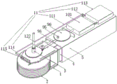
Fig. 1 is a schematic structural diagram of a carbon brush structure of a fan motor according to the present invention;
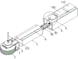
fig. 2 is an exploded view of a carbon brush structure of a fan motor according to the present invention;
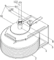
fig. 3 is a schematic structural diagram of a mounting frame and a conductive carbon wheel in a carbon brush structure of a fan motor according to the present invention;
fig. 4 is an enlarged view of a structure at a position a of the carbon brush structure of the fan motor according to the present invention;
fig. 5 is a schematic structural diagram of an air suction mechanism in a carbon brush structure of a fan motor according to the present invention;
fig. 6 is an enlarged view of a structure at a position B of the carbon brush structure of the fan motor according to the present invention.
In the figure: the device comprises a mounting frame 1, a conductive carbon wheel 2, a conductive core column 3, an insertion block 4, an insertion cylinder 5, a limiting strip 6, a limiting groove 7, an elastic connecting piece 8, an outer cylinder 81, an inner rod 82, an installation bolt 83, a spring I84, a driving component 9, a module gear I91, a driving shaft 92, a module gear II 93, a driving rib ring 94, a driven shaft 95, an eccentric wheel 96, a suction mechanism 10, a sealing box 101, a piston plate 102, a driving plate 103, a connecting rod 104, a spring II 105, an absorption component 11, an installation pipe 111, a check valve 112, a powder collecting box 113, a fixing box 114, a suction hole 115, a conductive component 12, a conductive cylinder 121, a power core rod 122, a clamping ring 123 and a clamping groove 124.
Detailed Description
The technical solutions in the embodiments of the present invention will be clearly and completely described below with reference to the drawings in the embodiments of the present invention, and it is obvious that the described embodiments are only a part of the embodiments of the present invention, and not all of the embodiments.
Referring to fig. 1-6, a carbon brush structure of a fan motor comprises a mounting frame 1, wherein a conductive core column 3 is rotatably connected to the side surface of the mounting frame 1, one end of the conductive core column 3 penetrates through the mounting frame 1, a conductive component 12 is arranged at the end of the conductive core column 3 penetrating through the mounting frame 1, a conductive carbon wheel 2 is fixedly sleeved on the outer edge of the conductive core column 3, the material of the conductive carbon wheel 2 is the same as that of a traditional carbon brush, an insertion block 4 is fixedly connected to the side surface of the mounting frame 1, an insertion cylinder 5 is movably sleeved on the outer edge of the insertion block 4, the insertion block 4 is connected with the insertion cylinder 5 through an elastic connecting piece 8, the side surface of the insertion block 4 is attached to the inner surface of the insertion cylinder 5, and the stability of the conductive carbon wheel 2 during operation can be ensured;
the mounting frame 1 and the inserting cylinder 5 are jointly provided with a driving assembly 9, the inserting cylinder 5 is further provided with an air suction mechanism 10 matched with the driving assembly 9 for working, and the mounting frame 1 is provided with an absorption assembly 11.
Referring to fig. 2, the elastic connecting member 8 includes an outer cylinder 81, an inner rod 82, a mounting bolt 83 and a first spring 84, the inner rod 82 is movably inserted into the outer cylinder 81, the outer edge of the inner rod 82 is attached to the inner surface of the outer cylinder 81, so that the stability of the inner rod 82 can be ensured, one end of the inner rod 82, which is located outside the outer cylinder 81, is fixedly connected to the side surface of the insertion block 4, one end of the mounting bolt 83 is fixedly connected to one end of the outer cylinder 81, the mounting bolt 83 penetrates through the inner bottom surface of the insertion cylinder 5, one end of the first spring 84 is connected to the outer edge of the outer cylinder 81, the other end of the first spring 84 is connected to the side surface of the insertion block 4, and under the action of the elastic connecting member 8, the conductive carbon wheel 2 can always contact with the collector ring, so that the stability of current transmission is ensured;
the outer edge of the mounting bolt 83 is in threaded sleeve connection with the nut, and the outer edge of the nut is tightly attached to the side face of the plug-in cylinder 5, so that a user can conveniently mount the elastic connecting piece 8 on the plug-in cylinder 5.
Referring to fig. 3-4, the driving assembly 9 includes a first module gear 91, a driving shaft 92, a second module gear 93, a driving rib ring 94, a driven shaft 95 and an eccentric wheel 96, the first module gear 91 is fixedly sleeved on one end of the conductive core column 3 penetrating through the mounting frame 1, the driving shaft 92 is rotatably connected to the side surface of the mounting frame 1, the second module gear 93 is fixedly sleeved on the driving shaft 92, and the first module gear 91 is meshed with the second module gear 93;
the driven shaft 95 is rotatably connected to the side face of the inserting cylinder 5, the outer edges of the driving shaft 92 and the driven shaft 95 are fixedly sleeved with rollers, annular grooves are formed in the outer edges of the two rollers, one end of the transmission rib ring 94 is sleeved in one of the annular grooves, the other end of the transmission rib ring 94 is sleeved in the other annular groove, the transmission rib ring 94 can be prevented from falling off from the two rollers by arranging the annular grooves, the transmission effect of the transmission rib ring 94 is further ensured, and the eccentric wheel 96 is fixedly sleeved on the driven shaft 95.
Referring to fig. 5, the suction mechanism 10 includes a sealing box 101, a piston plate 102, a driving plate 103, a connecting rod 104 and a second spring 105, the sealing box 101 is fixedly connected to a side surface of the insertion tube 5, the piston plate 102 is hermetically and slidably connected to an inner surface of the sealing box 101, one end of the second spring 105 is connected to the inner surface of the sealing box 101, the other end of the second spring 105 is connected to a side surface of the piston plate 102, one end of the connecting rod 104 is fixedly connected to the side surface of the piston plate 102, the other end of the connecting rod 104 extends to an outside of the sealing box 101 and is fixedly connected to a side surface of the driving plate 103, and a side surface of the driving plate 103 is attached to an outer edge of the eccentric wheel 96, so that the driving plate 103 is conveniently pressed by the eccentric wheel 96 to move the driving plate 103.
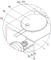
Referring to fig. 1 and 5, the absorption assembly 11 includes two installation pipes 111, two check valves 112, a powder collection box 113, a fixed box 114 and a plurality of suction holes 115, one end of each of the two installation pipes 111 is communicated with the sealing box 101, the two check valves 112 are respectively installed on the two installation pipes 111, the fixed box 114 is fixedly connected to the side surface of the installation frame 1, the suction holes 115 penetrate through the side surface of the fixed box 114, the suction holes 115 are uniformly distributed on the fixed box 114, so that the suction holes 115 can uniformly and comprehensively absorb carbon powder, the powder collection box 113 is installed on the side surface of the insertion tube 5, the powder collection box 113 is of a detachable structure, the specific connection mode between the powder collection box 113 and the insertion tube 5 is the prior art, and is not an innovation point of the technical solution, and is not shown in the figures, and is not described herein;
one end of one of the mounting tubes 111, which is far away from the sealing box 101, is communicated with the fixed box 114, and one end of the other mounting tube 111, which is far away from the sealing box 101, is communicated with the powder collecting box 113.
Referring to fig. 6, conductive component 12 includes electrically conductive section of thick bamboo 121, electric core pole 122, a plurality of joint rings 123 and a plurality of joint groove 124, electrically conductive section of thick bamboo 121 fixed connection is in the one end of electrically conductive stem 3, electric core pole 122 rotates the inner face of connecting at electrically conductive section of thick bamboo 121, the outer fringe at electric core pole 122 is all fixed to fix the cover in a plurality of joint rings 123, the inner face at electrically conductive section of thick bamboo 121 is all seted up to a plurality of joint grooves 124, a plurality of joint rings 123 are located a plurality of joint grooves 124 respectively, through setting up a plurality of joint rings 123 and a plurality of joint grooves 124, can prevent that electric core pole 122 from droing in electrically conductive section of thick bamboo 121, continuity when guaranteeing current transmission.
Referring to fig. 1, the diameter ratio of the first module gear 91 to the second module gear 93 is 4:1, and under the condition that the rotation speed of the conductive carbon wheel 2 is limited, the driving shaft 92 can rotate at a rotation speed four times the rotation speed of the conductive core column 3, so that air flow can rapidly flow in the sealing box 101, the fixing box 114 and the powder collecting box 113, and the absorption effect on carbon powder is further ensured.
Referring to fig. 2, two upper and lower equal fixedly connected with spacing 6 in side of a grafting piece 4, spacing groove 7 has all been seted up to the upper and lower inner face of a grafting section of thick bamboo 5, and two spacing 6 are located two spacing inslots 7 respectively, and the outer fringe of two spacing 6 laminates with the inner face of two spacing grooves 7 respectively mutually, and two spacing 6 play limiting displacement with two spacing grooves 7 to the removal of grafting piece 4, prevent that the grafting piece 4 from rocking in a grafting section of thick bamboo 5.
Referring to fig. 6, the outer edge of the electric core rod 122 is attached to the inner surface of the conductive tube 121, and the outer edges of the clamping rings 123 are attached to the inner surfaces of the clamping grooves 124, so that the stability of the electric core rod 122 in the conductive tube 121 can be ensured.
Referring to fig. 5, the two check valves 112 are restricted in opposite directions so that the seal box 101 can suck toner into the toner container 113.
When the invention is used, the conductive carbon wheel 2 can always contact with the outer edge of the rotating collecting ring, the conductive carbon wheel 2 can rotate under the action of friction force between the conductive carbon wheel 2 and the collecting ring, the traditional carbon brush structure is replaced, sliding friction between the carbon brush and the collecting ring is changed into rolling friction, the loss generated in the use process of the conductive carbon wheel 2 is greatly reduced, current generated in the running process of a motor can be transmitted through the conductive carbon wheel 2, the conductive core column 3, the conductive cylinder 121 and the electric core rod 122, it needs to be noted that a first spring 84 in the elastic connecting piece 8 is always in a compressed state in the working process of the conductive carbon wheel 2, under the action of the elastic force of the first spring 84, the insertion block 4 always moves towards the outside of the insertion cylinder 5, so that the conductive carbon wheel 2 can work tightly against the collecting ring, and the continuous transmission of current is ensured.
The conductive carbon wheel 2 can drive the conductive core column 3 to rotate in the rotating process, the conductive core column 3 can drive the driving shaft 92 to rotate through the first module gear 91 and the second module gear 93 which are meshed with each other when rotating, the driving shaft 92 can drive the driven shaft 95 to rotate through the driving rib ring 94 in the rotating process, finally, the eccentric wheel 96 on the driven shaft 95 rotates, the eccentric wheel 96 can continuously extrude the driving plate 103 in the rotating process, in the extruding process of the driving plate 103, when the driving plate 103 moves towards the direction of the sealing box 101, the driving plate 103 can drive the piston plate 102 to move through the connecting rod 104 and extrude the second spring 105, when the eccentric wheel 96 does not apply acting force to the driving plate 103, under the elastic force action of the second spring 105, the piston plate 102 can move towards the reverse direction, and along with the rotation of the eccentric wheel 96 based on the above process, the piston plate 102 is capable of continuous reciprocating movement within the sealed box 101.
It should be noted that, since the diameter ratio of the first module gear 91 to the second module gear 93 is 4:1, so under the limited circumstances of electrically conductive carbon wheel 2 slew velocity, driving shaft 92 can rotate with the quadruple rotational speed of electrically conductive stem 3 slew velocity for driven shaft 95 can drive eccentric wheel 96 and rotate fast, and then makes piston plate 102 quick reciprocating motion in seal box 101, makes the air current can be quick flow in seal box 101, fixed box 114 and collection powder box 113, and this is the key of the carbon powder that produces when the device can absorb electrically conductive carbon wheel 2 and collector ring friction.
Because one check valve 112 limits the air flow to flow out of the sealing box 101 only, and the other check valve 112 limits the air flow to flow into the sealing box 101 only, in the process of reciprocating movement of the piston plate 102, the sealing box 101 can pump out the air in the fixing box 114 through one mounting tube 111, and under the negative pressure, the carbon powder generated when the conductive carbon wheel 2 and the collecting ring rub against each other can be sucked into the fixing box 114 through the plurality of suction holes 115 and finally enters the collecting box 113 through the other mounting tube 111, so that the carbon powder generated when the conductive carbon wheel 2 works is collected and cleaned, and the carbon powder is prevented from scattering in the motor.
The above description is only for the preferred embodiment of the present invention, but the scope of the present invention is not limited thereto, and any person skilled in the art should be considered to be within the technical scope of the present invention, and the technical solutions and the inventive concepts thereof according to the present invention should be equivalent or changed within the scope of the present invention.
Claims (9)
1. The carbon brush structure of the fan motor is characterized by comprising a mounting frame (1), wherein a conductive core column (3) is rotatably connected to the side face of the mounting frame (1), one end of the conductive core column (3) penetrates through the mounting frame (1), a conductive assembly (12) is arranged at the end, penetrating through the mounting frame (1), of the conductive core column (3), a conductive carbon wheel (2) is fixedly sleeved on the outer edge of the conductive core column (3), an insertion block (4) is fixedly connected to the side face of the mounting frame (1), an insertion barrel (5) is movably sleeved on the outer edge of the insertion block (4), and the insertion block (4) is connected with the insertion barrel (5) through an elastic connecting piece (8);
the mounting rack (1) and the plug-in cylinder (5) are jointly provided with a driving assembly (9), the plug-in cylinder (5) is also provided with an air suction mechanism (10) which is matched with the driving assembly (9) to work, and the mounting rack (1) is provided with an absorption assembly (11);
the driving assembly (9) comprises a first module gear (91), a driving shaft (92), a second module gear (93), a transmission rib ring (94), a driven shaft (95) and an eccentric wheel (96), the first module gear (91) is fixedly sleeved at one end, penetrating through the mounting frame (1), of the conductive core column (3), the driving shaft (92) is rotatably connected to the side face of the mounting frame (1), the second module gear (93) is fixedly sleeved on the driving shaft (92), and the first module gear (91) is meshed with the second module gear (93);
the driven shaft (95) is rotatably connected to the side face of the inserting cylinder (5), the outer edges of the driving shaft (92) and the driven shaft (95) are fixedly sleeved with rollers, annular grooves are formed in the outer edges of the two rollers, one end of the transmission rib ring (94) is sleeved in one of the annular grooves, the other end of the transmission rib ring (94) is sleeved in the other annular groove, and the eccentric wheel (96) is fixedly sleeved on the driven shaft (95).
2. The carbon brush structure of the fan motor according to claim 1, wherein the elastic connecting piece (8) comprises an outer cylinder (81), an inner rod (82), a mounting bolt (83) and a first spring (84), the inner rod (82) is movably inserted into the outer cylinder (81), one end of the inner rod (82) located outside the outer cylinder (81) is fixedly connected with the side face of the insertion block (4), one end of the mounting bolt (83) is fixedly connected with one end of the outer cylinder (81), the mounting bolt (83) penetrates through the inner bottom face of the insertion cylinder (5), one end of the first spring (84) is connected with the outer edge of the outer cylinder (81), and the other end of the first spring (84) is connected with the side face of the insertion block (4);
the outer edge of the mounting bolt (83) is sleeved with a nut in a threaded manner, and the outer edge of the nut is tightly attached to the side face of the inserting cylinder (5).
3. The carbon brush structure of the fan motor according to claim 1, wherein the air suction mechanism (10) comprises a seal box (101), a piston plate (102), a driving plate (103), a connecting rod (104) and a second spring (105), the sealing box (101) is fixedly connected to the side surface of the insertion cylinder (5), the piston plate (102) is connected to the inner surface of the sealing box (101) in a sealing and sliding manner, one end of the second spring (105) is connected with the inner surface of the sealing box (101), the other end of the second spring (105) is connected with the side surface of the piston plate (102), one end of the connecting rod (104) is fixedly connected with the side surface of the piston plate (102), the other end of the connecting rod (104) extends to the outside of the sealing box (101), and the side surface of the driving plate (103) is fixedly connected with the side surface of the eccentric wheel (96).
4. The carbon brush structure of the fan motor according to claim 3, wherein the absorption assembly (11) comprises two installation pipes (111), two check valves (112), a powder collection box (113), a fixed box (114) and a plurality of suction holes (115), one ends of the two installation pipes (111) are communicated with the sealing box (101), the two check valves (112) are respectively installed on the two installation pipes (111), the fixed box (114) is fixedly connected to the side surface of the installation frame (1), the suction holes (115) penetrate through the side surface of the fixed box (114), the powder collection box (113) is installed on the side surface of the insertion cylinder (5), and the powder collection box (113) is of a detachable structure;
one end of one of the mounting tubes (111) far away from the sealing box (101) is communicated with the fixed box (114), and the other end of the mounting tube (111) far away from the sealing box (101) is communicated with the powder collecting box (113).
5. The carbon brush structure of the fan motor according to claim 1, wherein the conductive assembly (12) includes a conductive cylinder (121), a core rod (122), a plurality of snap rings (123) and a plurality of snap grooves (124), the conductive cylinder (121) is fixedly connected to one end of the conductive core column (3), the core rod (122) is rotatably connected to an inner surface of the conductive cylinder (121), the snap rings (123) are fixedly sleeved on an outer edge of the core rod (122), the snap grooves (124) are arranged on an inner surface of the conductive cylinder (121), and the snap rings (123) are respectively located in the snap grooves (124).
6. The carbon brush structure of the fan motor according to claim 1, wherein a diameter ratio of the first module gear (91) to the second module gear (93) is 4: 1.
7. The carbon brush structure of the fan motor according to claim 1, wherein the upper side surface and the lower side surface of the insertion block (4) are fixedly connected with limiting strips (6), the upper inner surface and the lower inner surface of the insertion cylinder (5) are respectively provided with limiting grooves (7), the two limiting strips (6) are respectively located in the two limiting grooves (7), and outer edges of the two limiting strips (6) are respectively attached to the inner surfaces of the two limiting grooves (7).
8. The carbon brush structure of the fan motor according to claim 5, wherein outer edges of the core bar (122) and inner surfaces of the conductive cylinders (121) are attached to each other, and outer edges of the plurality of snap rings (123) are respectively attached to inner surfaces of the plurality of snap grooves (124).
9. The carbon brush structure of a fan motor according to claim 5, wherein the flow limiting directions of the two check valves (112) are opposite.
Priority Applications (1)
| Application Number | Priority Date | Filing Date | Title |
|---|---|---|---|
| CN202210032003.8A CN114050460B (en) | 2022-01-12 | 2022-01-12 | Carbon brush structure of fan motor |
Applications Claiming Priority (1)
| Application Number | Priority Date | Filing Date | Title |
|---|---|---|---|
| CN202210032003.8A CN114050460B (en) | 2022-01-12 | 2022-01-12 | Carbon brush structure of fan motor |
Publications (2)
| Publication Number | Publication Date |
|---|---|
| CN114050460A true CN114050460A (en) | 2022-02-15 |
| CN114050460B CN114050460B (en) | 2022-03-18 |
Family
ID=80196340
Family Applications (1)
| Application Number | Title | Priority Date | Filing Date |
|---|---|---|---|
| CN202210032003.8A Active CN114050460B (en) | 2022-01-12 | 2022-01-12 | Carbon brush structure of fan motor |
Country Status (1)
| Country | Link |
|---|---|
| CN (1) | CN114050460B (en) |
Cited By (1)
| Publication number | Priority date | Publication date | Assignee | Title |
|---|---|---|---|---|
| CN116534521A (en) * | 2023-07-05 | 2023-08-04 | 苏州英特吉医疗设备有限公司 | Conductive conveying equipment and working method thereof |
Citations (2)
| Publication number | Priority date | Publication date | Assignee | Title |
|---|---|---|---|---|
| CN101855810A (en) * | 2007-11-13 | 2010-10-06 | 法雷奥电机设备公司 | Rotary electric machine for automobile |
| WO2020148014A1 (en) * | 2019-01-14 | 2020-07-23 | Bayerische Motoren Werke Aktiengesellschaft | Passively-cooled brush module for a slip ring system of an electric machine energised by current, electric machine and motor vehicle |
-
2022
- 2022-01-12 CN CN202210032003.8A patent/CN114050460B/en active Active
Patent Citations (2)
| Publication number | Priority date | Publication date | Assignee | Title |
|---|---|---|---|---|
| CN101855810A (en) * | 2007-11-13 | 2010-10-06 | 法雷奥电机设备公司 | Rotary electric machine for automobile |
| WO2020148014A1 (en) * | 2019-01-14 | 2020-07-23 | Bayerische Motoren Werke Aktiengesellschaft | Passively-cooled brush module for a slip ring system of an electric machine energised by current, electric machine and motor vehicle |
Cited By (2)
| Publication number | Priority date | Publication date | Assignee | Title |
|---|---|---|---|---|
| CN116534521A (en) * | 2023-07-05 | 2023-08-04 | 苏州英特吉医疗设备有限公司 | Conductive conveying equipment and working method thereof |
| CN116534521B (en) * | 2023-07-05 | 2023-09-29 | 苏州英特吉医疗设备有限公司 | Conductive conveying equipment and working method thereof |
Also Published As
| Publication number | Publication date |
|---|---|
| CN114050460B (en) | 2022-03-18 |
Similar Documents
| Publication | Publication Date | Title |
|---|---|---|
| CN114050460B (en) | Carbon brush structure of fan motor | |
| CN109822134B (en) | Air pollution prevention electric power construction equipment for low-voltage electrician | |
| CN210142956U (en) | Telescopic rotary machine core | |
| CN111468440B (en) | Insulator dust removal equipment driven by wind power | |
| CN212793000U (en) | Forming and pressurizing device for powder metallurgy automobile synchronizer gear hub | |
| CN109916635B (en) | Aeroengine thrust detection equipment | |
| CN216143125U (en) | Lead rolling ball screw pair | |
| CN110739802A (en) | motor with heat dissipation structure for electromechanical equipment | |
| CN114498346A (en) | Switch board with dust removal effect | |
| CN202208007U (en) | Reciprocating type electric multipurpose tool | |
| CN211359748U (en) | Electric tool for removing waste lubricating grease | |
| CN210240471U (en) | Novel oil lubrication servo cylinder | |
| CN107855884B (en) | Polishing device for propeller machining | |
| CN214022145U (en) | Gear double-end-face dirt removing device | |
| CN219811750U (en) | Carbon brush structure | |
| CN214321034U (en) | Clean mechanism in hole O of making a video recording | |
| CN219115122U (en) | Blackboard eraser convenient to clean | |
| CN210378777U (en) | Locking device | |
| CN214055189U (en) | Ball screw sliding table with dust removal structure | |
| CN213346696U (en) | Single-motor driven multidirectional reciprocating type massage transmission mechanism | |
| CN214888783U (en) | Lubricating and oiling device for nut shaft driving lead screw machining | |
| CN216618442U (en) | Dustproof ball screw | |
| CN212412910U (en) | Building motor convenient to clearance inner chamber dust | |
| CN116674098B (en) | Positioning and cutting device for asbestos-free calcium carbonate plate | |
| CN217749985U (en) | Welding device for machining inner magnetic rotor of magnetic pump |
Legal Events
| Date | Code | Title | Description |
|---|---|---|---|
| PB01 | Publication | ||
| PB01 | Publication | ||
| SE01 | Entry into force of request for substantive examination | ||
| SE01 | Entry into force of request for substantive examination | ||
| GR01 | Patent grant | ||
| GR01 | Patent grant |