CN114040725A - Laser system with controlled emission of coolant and laser based on applicator position - Google Patents
Laser system with controlled emission of coolant and laser based on applicator position Download PDFInfo
- Publication number
- CN114040725A CN114040725A CN202080044247.7A CN202080044247A CN114040725A CN 114040725 A CN114040725 A CN 114040725A CN 202080044247 A CN202080044247 A CN 202080044247A CN 114040725 A CN114040725 A CN 114040725A
- Authority
- CN
- China
- Prior art keywords
- biological tissue
- constructed
- laser
- applicator
- coolant
- Prior art date
- Legal status (The legal status is an assumption and is not a legal conclusion. Google has not performed a legal analysis and makes no representation as to the accuracy of the status listed.)
- Pending
Links
Images


Classifications
-
- A—HUMAN NECESSITIES
- A61—MEDICAL OR VETERINARY SCIENCE; HYGIENE
- A61B—DIAGNOSIS; SURGERY; IDENTIFICATION
- A61B18/00—Surgical instruments, devices or methods for transferring non-mechanical forms of energy to or from the body
- A61B18/18—Surgical instruments, devices or methods for transferring non-mechanical forms of energy to or from the body by applying electromagnetic radiation, e.g. microwaves
- A61B18/20—Surgical instruments, devices or methods for transferring non-mechanical forms of energy to or from the body by applying electromagnetic radiation, e.g. microwaves using laser
- A61B18/203—Surgical instruments, devices or methods for transferring non-mechanical forms of energy to or from the body by applying electromagnetic radiation, e.g. microwaves using laser applying laser energy to the outside of the body
-
- A—HUMAN NECESSITIES
- A61—MEDICAL OR VETERINARY SCIENCE; HYGIENE
- A61B—DIAGNOSIS; SURGERY; IDENTIFICATION
- A61B18/00—Surgical instruments, devices or methods for transferring non-mechanical forms of energy to or from the body
- A61B18/18—Surgical instruments, devices or methods for transferring non-mechanical forms of energy to or from the body by applying electromagnetic radiation, e.g. microwaves
- A61B18/20—Surgical instruments, devices or methods for transferring non-mechanical forms of energy to or from the body by applying electromagnetic radiation, e.g. microwaves using laser
- A61B18/22—Surgical instruments, devices or methods for transferring non-mechanical forms of energy to or from the body by applying electromagnetic radiation, e.g. microwaves using laser the beam being directed along or through a flexible conduit, e.g. an optical fibre; Couplings or hand-pieces therefor
-
- A—HUMAN NECESSITIES
- A61—MEDICAL OR VETERINARY SCIENCE; HYGIENE
- A61B—DIAGNOSIS; SURGERY; IDENTIFICATION
- A61B90/00—Instruments, implements or accessories specially adapted for surgery or diagnosis and not covered by any of the groups A61B1/00 - A61B50/00, e.g. for luxation treatment or for protecting wound edges
- A61B90/06—Measuring instruments not otherwise provided for
-
- A—HUMAN NECESSITIES
- A61—MEDICAL OR VETERINARY SCIENCE; HYGIENE
- A61N—ELECTROTHERAPY; MAGNETOTHERAPY; RADIATION THERAPY; ULTRASOUND THERAPY
- A61N5/00—Radiation therapy
- A61N5/06—Radiation therapy using light
- A61N5/0613—Apparatus adapted for a specific treatment
- A61N5/0616—Skin treatment other than tanning
-
- A—HUMAN NECESSITIES
- A61—MEDICAL OR VETERINARY SCIENCE; HYGIENE
- A61N—ELECTROTHERAPY; MAGNETOTHERAPY; RADIATION THERAPY; ULTRASOUND THERAPY
- A61N5/00—Radiation therapy
- A61N5/06—Radiation therapy using light
- A61N5/067—Radiation therapy using light using laser light
-
- A—HUMAN NECESSITIES
- A61—MEDICAL OR VETERINARY SCIENCE; HYGIENE
- A61B—DIAGNOSIS; SURGERY; IDENTIFICATION
- A61B17/00—Surgical instruments, devices or methods
- A61B2017/00017—Electrical control of surgical instruments
- A61B2017/00022—Sensing or detecting at the treatment site
- A61B2017/00039—Electric or electromagnetic phenomena other than conductivity, e.g. capacity, inductivity, Hall effect
-
- A—HUMAN NECESSITIES
- A61—MEDICAL OR VETERINARY SCIENCE; HYGIENE
- A61B—DIAGNOSIS; SURGERY; IDENTIFICATION
- A61B17/00—Surgical instruments, devices or methods
- A61B2017/00017—Electrical control of surgical instruments
- A61B2017/00022—Sensing or detecting at the treatment site
- A61B2017/00075—Motion
-
- A—HUMAN NECESSITIES
- A61—MEDICAL OR VETERINARY SCIENCE; HYGIENE
- A61B—DIAGNOSIS; SURGERY; IDENTIFICATION
- A61B18/00—Surgical instruments, devices or methods for transferring non-mechanical forms of energy to or from the body
- A61B2018/00005—Cooling or heating of the probe or tissue immediately surrounding the probe
- A61B2018/00011—Cooling or heating of the probe or tissue immediately surrounding the probe with fluids
- A61B2018/00017—Cooling or heating of the probe or tissue immediately surrounding the probe with fluids with gas
-
- A—HUMAN NECESSITIES
- A61—MEDICAL OR VETERINARY SCIENCE; HYGIENE
- A61B—DIAGNOSIS; SURGERY; IDENTIFICATION
- A61B18/00—Surgical instruments, devices or methods for transferring non-mechanical forms of energy to or from the body
- A61B2018/00005—Cooling or heating of the probe or tissue immediately surrounding the probe
- A61B2018/00011—Cooling or heating of the probe or tissue immediately surrounding the probe with fluids
- A61B2018/00029—Cooling or heating of the probe or tissue immediately surrounding the probe with fluids open
-
- A—HUMAN NECESSITIES
- A61—MEDICAL OR VETERINARY SCIENCE; HYGIENE
- A61B—DIAGNOSIS; SURGERY; IDENTIFICATION
- A61B18/00—Surgical instruments, devices or methods for transferring non-mechanical forms of energy to or from the body
- A61B2018/00315—Surgical instruments, devices or methods for transferring non-mechanical forms of energy to or from the body for treatment of particular body parts
- A61B2018/00452—Skin
- A61B2018/0047—Upper parts of the skin, e.g. skin peeling or treatment of wrinkles
-
- A—HUMAN NECESSITIES
- A61—MEDICAL OR VETERINARY SCIENCE; HYGIENE
- A61B—DIAGNOSIS; SURGERY; IDENTIFICATION
- A61B18/00—Surgical instruments, devices or methods for transferring non-mechanical forms of energy to or from the body
- A61B2018/00315—Surgical instruments, devices or methods for transferring non-mechanical forms of energy to or from the body for treatment of particular body parts
- A61B2018/00452—Skin
- A61B2018/00476—Hair follicles
-
- A—HUMAN NECESSITIES
- A61—MEDICAL OR VETERINARY SCIENCE; HYGIENE
- A61B—DIAGNOSIS; SURGERY; IDENTIFICATION
- A61B18/00—Surgical instruments, devices or methods for transferring non-mechanical forms of energy to or from the body
- A61B2018/00636—Sensing and controlling the application of energy
- A61B2018/00642—Sensing and controlling the application of energy with feedback, i.e. closed loop control
-
- A—HUMAN NECESSITIES
- A61—MEDICAL OR VETERINARY SCIENCE; HYGIENE
- A61B—DIAGNOSIS; SURGERY; IDENTIFICATION
- A61B18/00—Surgical instruments, devices or methods for transferring non-mechanical forms of energy to or from the body
- A61B2018/0091—Handpieces of the surgical instrument or device
- A61B2018/00916—Handpieces of the surgical instrument or device with means for switching or controlling the main function of the instrument or device
- A61B2018/00928—Handpieces of the surgical instrument or device with means for switching or controlling the main function of the instrument or device by sending a signal to an external energy source
-
- A—HUMAN NECESSITIES
- A61—MEDICAL OR VETERINARY SCIENCE; HYGIENE
- A61B—DIAGNOSIS; SURGERY; IDENTIFICATION
- A61B18/00—Surgical instruments, devices or methods for transferring non-mechanical forms of energy to or from the body
- A61B18/18—Surgical instruments, devices or methods for transferring non-mechanical forms of energy to or from the body by applying electromagnetic radiation, e.g. microwaves
- A61B18/20—Surgical instruments, devices or methods for transferring non-mechanical forms of energy to or from the body by applying electromagnetic radiation, e.g. microwaves using laser
- A61B2018/2015—Miscellaneous features
- A61B2018/202—Laser enclosed in a hand-piece
-
- A—HUMAN NECESSITIES
- A61—MEDICAL OR VETERINARY SCIENCE; HYGIENE
- A61B—DIAGNOSIS; SURGERY; IDENTIFICATION
- A61B18/00—Surgical instruments, devices or methods for transferring non-mechanical forms of energy to or from the body
- A61B18/18—Surgical instruments, devices or methods for transferring non-mechanical forms of energy to or from the body by applying electromagnetic radiation, e.g. microwaves
- A61B18/20—Surgical instruments, devices or methods for transferring non-mechanical forms of energy to or from the body by applying electromagnetic radiation, e.g. microwaves using laser
- A61B2018/2035—Beam shaping or redirecting; Optical components therefor
- A61B2018/205545—Arrangements for particular spot shape, e.g. square or annular
-
- A—HUMAN NECESSITIES
- A61—MEDICAL OR VETERINARY SCIENCE; HYGIENE
- A61B—DIAGNOSIS; SURGERY; IDENTIFICATION
- A61B18/00—Surgical instruments, devices or methods for transferring non-mechanical forms of energy to or from the body
- A61B18/18—Surgical instruments, devices or methods for transferring non-mechanical forms of energy to or from the body by applying electromagnetic radiation, e.g. microwaves
- A61B18/20—Surgical instruments, devices or methods for transferring non-mechanical forms of energy to or from the body by applying electromagnetic radiation, e.g. microwaves using laser
- A61B18/22—Surgical instruments, devices or methods for transferring non-mechanical forms of energy to or from the body by applying electromagnetic radiation, e.g. microwaves using laser the beam being directed along or through a flexible conduit, e.g. an optical fibre; Couplings or hand-pieces therefor
- A61B2018/225—Features of hand-pieces
- A61B2018/2253—Features of hand-pieces characterised by additional functions, e.g. surface cooling or detecting pathological tissue
-
- A—HUMAN NECESSITIES
- A61—MEDICAL OR VETERINARY SCIENCE; HYGIENE
- A61N—ELECTROTHERAPY; MAGNETOTHERAPY; RADIATION THERAPY; ULTRASOUND THERAPY
- A61N5/00—Radiation therapy
- A61N2005/002—Cooling systems
- A61N2005/007—Cooling systems for cooling the patient
-
- A—HUMAN NECESSITIES
- A61—MEDICAL OR VETERINARY SCIENCE; HYGIENE
- A61N—ELECTROTHERAPY; MAGNETOTHERAPY; RADIATION THERAPY; ULTRASOUND THERAPY
- A61N5/00—Radiation therapy
- A61N5/06—Radiation therapy using light
- A61N2005/0626—Monitoring, verifying, controlling systems and methods
-
- A—HUMAN NECESSITIES
- A61—MEDICAL OR VETERINARY SCIENCE; HYGIENE
- A61N—ELECTROTHERAPY; MAGNETOTHERAPY; RADIATION THERAPY; ULTRASOUND THERAPY
- A61N5/00—Radiation therapy
- A61N5/06—Radiation therapy using light
- A61N2005/0635—Radiation therapy using light characterised by the body area to be irradiated
- A61N2005/0643—Applicators, probes irradiating specific body areas in close proximity
- A61N2005/0644—Handheld applicators
Landscapes
- Health & Medical Sciences (AREA)
- Life Sciences & Earth Sciences (AREA)
- Physics & Mathematics (AREA)
- Surgery (AREA)
- Engineering & Computer Science (AREA)
- Biomedical Technology (AREA)
- Veterinary Medicine (AREA)
- Public Health (AREA)
- Nuclear Medicine, Radiotherapy & Molecular Imaging (AREA)
- Animal Behavior & Ethology (AREA)
- General Health & Medical Sciences (AREA)
- Optics & Photonics (AREA)
- Heart & Thoracic Surgery (AREA)
- Medical Informatics (AREA)
- Molecular Biology (AREA)
- Electromagnetism (AREA)
- Otolaryngology (AREA)
- Pathology (AREA)
- Radiology & Medical Imaging (AREA)
- Biophysics (AREA)
- Oral & Maxillofacial Surgery (AREA)
- Laser Surgery Devices (AREA)
- Radiation-Therapy Devices (AREA)
- Media Introduction/Drainage Providing Device (AREA)
Abstract
The laser system includes a base unit having a power supply. A handheld applicator is connected with the base unit, the handheld applicator configured to engage biological tissue for treatment. A position detection structure is associated with the applicator for determining the position of the applicator relative to the engaged biological tissue. The laser source generates a laser beam. The cooling system provides a coolant to the biological tissue during treatment. The processor circuit is coupled to the position sensing structure, the laser source, and the cooling system. Based on the data received from the position detection structure, the processor circuit triggers the application of coolant to the treated biological tissue, or triggers the application of coolant to the treated biological tissue, followed by a time delay, and then triggers the laser source.
Description
Technical Field
Embodiments relate to laser systems for biological tissue treatments, such as epilation treatments and laser skin treatments, and more particularly, to laser systems that employ controlled firing of a coolant and a laser based on the position of an applicator or handpiece during tissue treatment.
Background
A conventional laser apparatus (e.g., an elliptical FRAX 1550 lattice non-ablative laser) includes a handpiece having a magnetic moving roller sensor that measures the speed of movement of the roller over the skin surface and indicates this speed to the operator. The device provides cooling air to continuously cool the skin being treated. A foot pedal is provided to activate the laser.
While this conventional laser device works well for its intended purpose, there is a need to provide a laser system with a Dynamic Cooling Device (DCD) and a handpiece applicator, wherein the system is constructed and arranged to control the DCD and the emission of the laser based on the position of the applicator relative to the tissue being treated.
Disclosure of Invention
The present embodiment aims to meet the above-mentioned need. In accordance with the principles of the embodiments, this object is achieved by a laser system comprising a base unit having a power supply. A handheld applicator is connected with the base unit and is constructed and arranged to engage biological tissue for treatment. A position detection structure is associated with the applicator and is constructed and arranged to determine the position of the applicator relative to the engaged biological tissue. The laser source is constructed and arranged to generate a laser beam. The cooling system is constructed and arranged to provide a source of coolant to the biological tissue during treatment. The processor circuit is coupled to the position sensing structure, the laser source, and the cooling system. The processor circuit is constructed and arranged to: based on the data received from the position detection structure, the application of coolant to the treated biological tissue is triggered, or the application of coolant to the treated biological tissue is triggered, followed by a time delay, and then the laser source is triggered.
According to another aspect of an embodiment, a handheld applicator for treating biological tissue includes a body constructed and arranged to be connected to a laser source. A magnetic roller is disposed at the distal end of the body. A magnetic field sensor is associated with the magnet roller and is constructed and arranged to detect a phase change when the magnet roller rotates. The valve is typically constructed and arranged with a nozzle to provide a source of coolant to the biological tissue during treatment. The trigger circuit is connected with the magnetic field sensor and the valve. The trigger circuit is constructed and arranged to: based on the number of phase changes detected by the magnetic field sensor as the magnetic roller rotates, a valve is triggered to apply coolant to the biological tissue being treated.
According to yet another aspect of an embodiment, a method of treating biological tissue with a laser system. The laser system includes: a handheld applicator constructed and arranged to engage biological tissue for treatment; a position detection structure associated with the applicator, the position detection structure being constructed and arranged to determine the position of the applicator relative to the engaged biological tissue; a laser source constructed and arranged to generate a laser beam; a cooling system constructed and arranged to provide a coolant to the biological tissue during treatment; and a processor circuit connected to the position detection structure, the laser source, and the cooling system. The method comprises the following steps: engaging the biological tissue with the applicator; moving the applicator relative to the engaged biological tissue; determining a position of the applicator relative to the engaged biological tissue using the position sensing structure; and triggering, with the processor circuit, the cooling system to provide coolant to the biological tissue during treatment based on the position of the applicator relative to the engaged biological tissue. After a time delay, the processor circuit triggers the laser source.
Other objects, features, and characteristics of the present embodiments, as well as the methods of operation and functions of the related elements of structure, the combination of parts and economies of manufacture, will become more apparent upon consideration of the following detailed description and the appended claims with reference to the accompanying drawings, all of which form a part of this specification.
Drawings
Fig. 1 is a perspective view of a laser system provided in accordance with an embodiment.
Fig. 2 is a schematic diagram of the laser system of fig. 1.
Fig. 3 is a partial schematic side view of an applicator of the laser system of fig. 2.
Fig. 4 is a partial schematic side view of another embodiment of an applicator of a laser system.
FIG. 5 is a schematic diagram for triggering a DCD spray valve and/or a laser source based on a signal detected by a magnetic field sensor of an embodiment.
FIG. 6 illustrates a trigger signal for triggering the DCD spray valve and the laser source, according to an embodiment.
FIG. 7 is a flow diagram of steps for performing a method of an embodiment.
FIG. 8 is a flow diagram of steps for performing a method of another embodiment.
Fig. 9 is a plan view of a continuous circular cross-section laser beam delivered to target tissue without overlap.
FIG. 10 is a plan view of a continuous circular cross-section laser beam delivered to target tissue with overlap.
FIG. 11 is a plan view of a continuous square cross-section laser beam delivered to target tissue without overlap.
FIG. 12 is a plan view of a continuous square cross-section laser beam delivered to target tissue with overlap.
Detailed Description
Referring to fig. 1, there is shown an embodiment of a laser system for treating biological tissue, generally designated 10. The system 10 may be used to non-invasively deliver radiation to a target biological tissue, such as skin or hair. The system 10 includes a base unit 12 and a delivery system, generally indicated at 14. In one embodiment, the laser radiation provided by the energy source 12 is directed to the target tissue via the delivery system 14. In the illustrated embodiment, the delivery system 14 includes an umbilical cable 16 and an applicator 18. The applicator 18 may be a handheld device (e.g., a handpiece) that can be held or manipulated by a user to irradiate the target tissue.
As shown in fig. 2, the base unit 12 is coupled to an umbilical cable 16, which umbilical cable 16 is connected to the delivery module 14. The base unit 12 includes a power supply 20 for supplying power to various system components including a laser source 22 housed in the base unit 12 for emitting a laser beam L (fig. 3) through the umbilical cable 16 and the applicator 18 to the target tissue. A foot pedal (not shown) or finger switch on the applicator 18 may be used to equip the laser source 22. The base unit 12 also includes a controller 24 coupled to the laser source 22 and coupleable to a user interface. The controller 24 includes a processor circuit 25.
The base unit 12 includes a cooling system 26 for minimizing undesirable thermal damage to the tissue. The cooling system 26 comprises a Dynamic Cooling Device (DCD) which prevents damage to the epidermis during laser epilation or skin treatment. The cooling system 26 contains a coolant, such as a source of cryogen gas C in the base unit 12. Referring to fig. 3, the DCD spray valve 27 at the applicator 18 is connected to a source of cryogen gas 29. DCD works by spraying the outer layer of skin with cryogen gas C through valve 27 (with nozzle 31). The cryogen gas may be applied directly to the skin for about 50ms before and/or after each laser pulse. DCD works by cooling the top layer of the skin without disturbing the underlying layers. This allows the targeted hair follicles, veins, and other layers of skin to be maintained at normal or near normal temperatures. Referring to FIG. 3, the umbilical cable 16 may be housed in at least one of an electrical communication line 28 and a cooling fluid line connected to the valve 27. Referring to fig. 4, the controller 24 and/or processor circuit 25 may alternatively be housed in the applicator 18' rather than in the base unit 12.
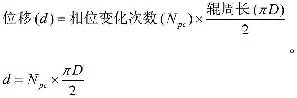
As shown in fig. 3 and 4, the applicator 18, 18' includes a body 29 and a position sensing structure, generally indicated at 30, disposed at a distal end of the body 29. In an embodiment, the position sensing structure 30 includes a magnetic roller 32 and a magnetic field sensor 34, such as a Hall effect sensor. As shown, the north and south poles of the magnet roller 32 are opposite to each other. The strength of the magnetic field generated by the magnet roller 32 is detected by a stationary magnetic field sensor 34 disposed generally adjacent to the magnet roller 32. When the magnetic roller 32 rotates along the skin surface S, the magnetic field sensor 34 detects a phase change caused by the rotating magnetic roller 32 (see step 40 in fig. 10). Referring to fig. 5, the algorithm 36 is executed by the processor circuit 25 to convert the phase change counted by the magnetic field sensor 34 into a displacement value for the magnet roller 32 according to the following equation:


the displacement signal 38 is received by a trigger circuit 41, which trigger circuit 41 may be considered to be part of the processor circuit 25. Referring to fig. 6, the DCD and laser firing sequence will be understood. Starting from the initial position of the handpiece on the target tissue, every nth phase change may trigger (open) the DCD spray valve 27 via the trigger circuit 41 such that only the coolant C is sprayed onto the target tissue via the nozzle 31 (step 42 in fig. 7), or the trigger circuit 41 may trigger the DCD spray valve 27 such that the coolant C is sprayed onto the target tissue via the nozzle 31 (step 42 in fig. 8), followed by a predetermined time delay (step 44 in fig. 8), and then the trigger circuit 41 may trigger the laser source 22 (step 46 in fig. 8). In order to deliver a perfect beam L (fig. 9, 11) to the target tissue without overlap, the displacement d is set equal to the beam width as measured in the direction of displacement. For the case where the light beams L overlap (fig. 10, 12), the displacement d is set to a fraction (e.g., 80%) of the beam width.
The resolution of the magnetic field sensor 34 may be improved by employing a plurality of hall effect sensors defining the magnetic field sensor 34, employing a plurality of magnets in the magnetic roller 32, or a combination of both. Alternatively, other embodiments of the position detection structure 30 may be employed. For example, the position of the roller 32 may be obtained with a rotary encoder (not shown) that measures direct linear motion. The circumference of the roller 32 is related to the Pulse Per Revolution (PPR) of the encoder. If the roller is rotated a full turn (360 degrees) the distance traveled will be equal to the circumference of the roller. A stabilizing roller (not shown) may be disposed adjacent the magnetic roller 32 on the opposite side of the cryogen spray to increase the stability of the applicator 18 as it rolls over the target tissue. The stabilizing roller helps to ensure that the applicator remains perpendicular to the skin surface. The position sensor works best when the displacement of the applicator is small relative to the time it takes to deliver the cryogen spray or cryogen spray and laser. A typical time is 10 to 100ms, which is associated with a maximum of 3.6mm displacement if travelling at a speed of 36mm/s (two 18mm beam widths per second). The displacement during the 3ms laser pulse is small, about 0.1mm for a speed of 36 mm/s.
The cross-section of the laser beam L on the tissue surface may be circular, rectangular, square or hexagonal in shape. Rectangular and square beams are the preferred choice for the case where 100% coverage is required without overlap. A prism may be provided to shape the laser beam L. Alternatively, optical fibers having circular or rectangular cores may be used. Or alternatively, a diffractive optical element may be used to convert a circular beam into a rectangular beam. Since usually a large area of skin or hair is being treated, it is preferred that the consecutive laser beams are directly adjacent (e.g. touching, fig. 9), or for better treatment coverage, the consecutive laser beams L may overlap (fig. 10).
The system 10 can be used for a variety of applications, such as hair removal, vascular lesion treatment (e.g., treatment of port wine stains and spider veins), and pigment reduction and skin rejuvenation (e.g., treatment of rosacea, acne, pigmented lesions, and sun-damaged skin). For use in epilation, the laser source 22 is preferably a 755nm Alexandrite laser; a semiconductor diode laser operating around 800nm, preferably at 805nm or 810 nm; and preferably 1064nm Nd with a depth of about 4 mm: one of YAG lasers. For use in vasculopathies and pigment treatments, the laser source 22 is preferably a 532nm KTP laser, 1064nm Nd: one of a YAG laser, a dye laser operating at 585nm or 595nm, or a 755 alexandrite laser. For vascular lesions, the treatment is preferably at a depth of about 1mm, and for pigment and skin rejuvenation, the treatment is preferably at a depth of about 0.1-0.2 mm. The system 10 works well for treating a significant area of tissue, such as vascular treatment over a large portion of the entire face, or epilation treatment over the legs or the back of a person.
The operations and algorithms described herein may be implemented as executable code within the processor circuit 25 as described, or stored on a separate computer or machine readable non-transitory tangible storage medium that is completed based on execution of the code by a processor circuit implemented using one or more integrated circuits. Example implementations of the disclosed circuitry include hardware logic implemented in logic arrays such as Programmable Logic Arrays (PLAs), Field Programmable Gate Arrays (FPGAs), or by mask programming of integrated circuits such as Application Specific Integrated Circuits (ASICs). Any of these circuits may also be implemented using software-based executable resources that are executed by a corresponding internal processor circuit, such as a microprocessor circuit (not shown), and implemented using one or more integrated circuits, where execution of executable code stored in the internal memory circuit causes the integrated circuit implementing the processor circuit to store application state variables in the processor memory, thereby creating an executable application resource (e.g., an application instance) that performs operations of the circuits as described herein. Thus, the term "circuitry" as used in this specification refers to both hardware-based circuitry implemented using one or more integrated circuits and including logic for performing the described operations, or software-based circuitry including a processor circuit 25 (implemented using one or more integrated circuits) that includes a reserved portion of processor memory for storing application state data and application variables that are modified by the processor circuit through execution of executable code. The memory circuit may be implemented, for example, using non-volatile memory (such as programmable read-only memory (PROM) or EPROM) and/or volatile memory (such as DRAM, etc.).
The foregoing preferred embodiments have been shown and described for the purposes of illustrating the structural and functional principles of the present invention, as well as illustrating the methods of employing the preferred embodiments, and are subject to change without departing from such principles. Accordingly, this invention includes all modifications encompassed within the spirit of the following claims.
Claims (25)
1. A laser system, comprising:
a base unit having a power source;
a handheld applicator connected with the base unit and constructed and arranged to engage biological tissue for treatment;
a position detection structure associated with the applicator, the position detection structure being constructed and arranged to determine the position of the applicator relative to the engaged biological tissue;
a laser source constructed and arranged to generate a laser beam;
a cooling system constructed and arranged to provide a source of coolant to the biological tissue during treatment; and
processor circuitry connected to the position detection structure, the laser source, and the cooling system;
wherein the processor circuit is constructed and arranged to: triggering application of the coolant to the treated biological tissue, followed by a time delay, and then triggering the laser source, based on data received from the position detection structure.
2. The system of claim 1, wherein the laser source, cooling system, and processing circuitry are all housed in the base unit.
3. The system of claim 1, wherein the laser source and cooling system are housed in the base unit, wherein the processor circuit is housed in the applicator.
4. The system of claim 1, wherein the position detection structure comprises a magnetic roller and a magnetic field sensor associated with the magnetic roller and constructed and arranged to detect a phase change when the magnetic roller rotates.
5. The system of claim 4, wherein the magnetic field sensor comprises at least one Hall effect sensor.
6. The system of claim 5, wherein the processor circuit is constructed and arranged to convert the phase change counted by the Hall effect sensor to a displacement value of the magnet roller.
7. The system of claim 6, wherein the processor circuit comprises a trigger circuit constructed and arranged to cause triggering of the coolant and the laser source based on displacement of the magnetic roller.
8. The system of claim 7, wherein the applicator comprises a spray valve constructed and arranged to be triggered by the trigger circuit between an open position and a closed position to deliver the coolant from the cooling system.
9. The system of claim 6, wherein the processor circuit is constructed and arranged to perform the following equation:

10. the system of claim 1, wherein the laser source is a 755nm alexandrite laser; a semiconductor diode laser operating around 800 nm; 1064nm Nd: a YAG laser; a 532nm KTP laser; or a dye laser operating at 585nm or 595 nm.
11. A laser system, comprising:
a base unit having a power source;
a handheld applicator connected with the base unit and constructed and arranged to engage biological tissue for treatment;
a position detection structure associated with the applicator, the position detection structure being constructed and arranged to determine the position of the applicator relative to the engaged biological tissue;
a cooling system constructed and arranged to provide a source of coolant to the biological tissue during treatment; and
a processor circuit connected with the position detection structure and the cooling system;
wherein the processor circuit is constructed and arranged to: triggering application of the coolant to the treated biological tissue based on data received from the position detection structure.
12. The system of claim 11, wherein the hand-held applicator comprises a spray valve constructed and arranged to supply the coolant once the spray valve is triggered by the processor circuit.
13. The system of claim 12, wherein the processor circuit is constructed and arranged to trigger the spray valve to supply the coolant for 10 to 100 ms.
14. The system of claim 13, wherein the coolant is a cryogen gas.
15. The system of claim 11, wherein the position detection structure comprises a magnetic roller and a magnetic field sensor associated with the magnetic roller and constructed and arranged to detect a phase change when the magnetic roller rotates.
16. A method of treating biological tissue with a laser system, the laser system comprising: a handheld applicator constructed and arranged to engage biological tissue for treatment; a position detection structure associated with the applicator, the position detection structure being constructed and arranged to determine the position of the applicator relative to the engaged biological tissue; a laser source constructed and arranged to generate a laser beam; a cooling system constructed and arranged to provide a coolant to the biological tissue during treatment; and processor circuitry connected to the position detection structure, the laser source, and the cooling system; the method comprises the following steps:
engaging the biological tissue with the applicator;
moving the applicator relative to the engaged biological tissue,
determining a position of the applicator relative to the engaged biological tissue using the position detection structure; and
triggering, with the processor circuit, the cooling system to provide the coolant to the biological tissue during treatment based on a position of the applicator relative to the engaged biological tissue.
17. The method of claim 16, further comprising the steps of:
waiting a predetermined time after triggering the cooling system; and
after waiting the predetermined time, triggering the laser source to deliver a laser beam to the biological tissue.
18. The method of claim 17, wherein the step of determining the position of the applicator comprises:
employing a magnetic roller and at least one hall effect sensor associated with the magnetic roller on the applicator such that the roller engages the biological tissue;
counting the number of phase changes of the magnetic roller by using the Hall effect sensor when the magnetic roller rotates; and
converting, via the processor circuit, the counted phase change to a displacement (d) of the magnet roller.
19. The method of claim 17, wherein the processor circuit executes the following equation:
20. the method of claim 19, wherein the displacement is set equal to a width of the laser beam to deliver the laser beam to the biological tissue without overlap.
21. The method of claim 20, wherein the laser beam is rectangular or square.
22. The method of claim 19, wherein the displacement is provided as a portion of a laser beam width to deliver the laser beam to the biological tissue with overlap.
23. The method of claim 22, wherein the laser beam is rectangular or square.
24. A hand-held applicator for treating biological tissue, comprising:
a body constructed and arranged to be connected to a laser source;
a magnetic roller disposed at a distal end of the body;
a magnetic field sensor associated with the magnetic roller and constructed and arranged to detect a phase change when the magnetic roller is rotated;
a valve constructed and arranged to provide a source of coolant to the biological tissue during treatment; and
a trigger circuit connected with the magnetic field sensor and the valve;
wherein the trigger circuit is constructed and arranged to: triggering the valve to apply the coolant to the treated biological tissue based on the number of phase changes detected by the magnetic field sensor as the magnetic roller rotates.
25. An applicator according to claim 24, in combination with the laser source, the trigger circuit being connected to the laser source, wherein the trigger circuit is constructed and arranged to trigger the laser source after triggering the valve.
Applications Claiming Priority (3)
| Application Number | Priority Date | Filing Date | Title |
|---|---|---|---|
| US16/395,291 | 2019-04-26 | ||
| US16/395,291 US11439463B2 (en) | 2019-04-26 | 2019-04-26 | Laser system with controlled firing of cooling agent and laser based on applicator position |
| PCT/US2020/028193 WO2020219308A1 (en) | 2019-04-26 | 2020-04-15 | Laser system with controlled firing of cooling agent and laser based on applicator position |
Publications (1)
| Publication Number | Publication Date |
|---|---|
| CN114040725A true CN114040725A (en) | 2022-02-11 |
Family
ID=70554207
Family Applications (1)
| Application Number | Title | Priority Date | Filing Date |
|---|---|---|---|
| CN202080044247.7A Pending CN114040725A (en) | 2019-04-26 | 2020-04-15 | Laser system with controlled emission of coolant and laser based on applicator position |
Country Status (8)
| Country | Link |
|---|---|
| US (1) | US11439463B2 (en) |
| EP (2) | EP4353308B1 (en) |
| JP (1) | JP7478753B2 (en) |
| KR (1) | KR102728891B1 (en) |
| CN (1) | CN114040725A (en) |
| AU (1) | AU2020263237B2 (en) |
| ES (1) | ES2999274T3 (en) |
| WO (1) | WO2020219308A1 (en) |
Families Citing this family (3)
| Publication number | Priority date | Publication date | Assignee | Title |
|---|---|---|---|---|
| USD995791S1 (en) * | 2021-04-15 | 2023-08-15 | Alura Inc. | Hair removal device |
| KR102573603B1 (en) * | 2023-01-17 | 2023-09-04 | 비손메디칼 주식회사 | Handpiece for skin laser treatment and medical laser treatment apparatus including the same |
| CN116392241B (en) * | 2023-04-28 | 2024-04-16 | 广州创造美科技有限公司 | Laser unhairing device |
Citations (15)
| Publication number | Priority date | Publication date | Assignee | Title |
|---|---|---|---|---|
| CN2153772Y (en) * | 1993-05-10 | 1994-01-19 | 高秀珍 | Displacement measuring counter |
| US5814040A (en) * | 1994-04-05 | 1998-09-29 | The Regents Of The University Of California | Apparatus and method for dynamic cooling of biological tissues for thermal mediated surgery |
| US20010009997A1 (en) * | 1999-01-29 | 2001-07-26 | Karl Pope | Dynamic cooling of tissue for radiation treatment |
| JP2003164534A (en) * | 2001-11-30 | 2003-06-10 | Nidek Co Ltd | Laser therapeutic instrument |
| CN1441230A (en) * | 2002-11-08 | 2003-09-10 | 许建平 | Magnetically inducing physical quantity sensor |
| US20070083190A1 (en) * | 2005-10-11 | 2007-04-12 | Yacov Domankevitz | Compression device for a laser handpiece |
| US20070255359A1 (en) * | 2006-04-20 | 2007-11-01 | Joseph Neev | Skin treatment and hair treatment device with protruding guards |
| US20070270785A1 (en) * | 2006-05-16 | 2007-11-22 | Jones Christopher J | Light beam wavelength mixing for hair removal |
| CN201218721Y (en) * | 2008-06-28 | 2009-04-08 | 桂林迪吉特电子有限公司 | Electronic digital display ranging wheel |
| US20120283711A1 (en) * | 2011-02-03 | 2012-11-08 | TRIA Beauty | Devices and Methods for Radiation-Based Dermatological Treatments |
| WO2013019785A1 (en) * | 2011-08-01 | 2013-02-07 | Miramar Labs, Inc. | Applicator and tissue interface module for dermatological device |
| US20130150841A1 (en) * | 2011-12-12 | 2013-06-13 | Kevin T. Schomacker | Devices for the treatment of biological tissue |
| CN107036520A (en) * | 2016-11-08 | 2017-08-11 | 浪潮(苏州)金融技术服务有限公司 | A kind of winding length monitoring device and method |
| CN109029232A (en) * | 2018-08-13 | 2018-12-18 | 成都太微电子科技有限公司 | A method of based on rotating excitation field displacement measurement |
| JP2019034211A (en) * | 2011-09-09 | 2019-03-07 | トリア ビューティ インコーポレイテッド | Device and method for radiation-based dermatological treatment |
Family Cites Families (12)
| Publication number | Priority date | Publication date | Assignee | Title |
|---|---|---|---|---|
| US6758845B1 (en) | 1999-10-08 | 2004-07-06 | Lumenis Inc. | Automatic firing apparatus and methods for laser skin treatment over large areas |
| US20070265605A1 (en) * | 2006-05-15 | 2007-11-15 | Light Instruments Ltd. | Apparatus and method for treating dental tissue |
| KR100864803B1 (en) | 2008-07-09 | 2008-10-23 | 주식회사 루트로닉 | Laser beam irradiation control device that controls the oscillation of the laser beam according to the movement of the handpiece |
| WO2012106682A1 (en) * | 2011-02-03 | 2012-08-09 | Tria Beauty, Inc. | Radiation-based dermatological devices and methods |
| US9414888B2 (en) * | 2011-02-03 | 2016-08-16 | Tria Beauty, Inc. | Devices and methods for radiation-based dermatological treatments |
| KR101300120B1 (en) * | 2011-04-11 | 2013-08-26 | 주식회사 루트로닉 | laser theraphy apparatus and control method of laser theraphy apparatus |
| US20150258351A1 (en) * | 2012-10-02 | 2015-09-17 | Ardent Sound, Inc. | Motion Mechanisms for Ultrasound Transducer Modules |
| ES2666123T3 (en) * | 2013-03-11 | 2018-05-03 | Biolase, Inc. | Fractional manual device for dermatological treatments |
| US10024690B2 (en) * | 2015-04-14 | 2018-07-17 | Texas Instruments Incorporated | Incremental rotary encoder using hall effect sensors and magnetic detents |
| KR20160146337A (en) * | 2015-06-12 | 2016-12-21 | 예림엔지니어링 주식회사 | Raser cooling gas control method for skin treatment and apparatus performing the same |
| KR101914742B1 (en) * | 2017-04-28 | 2018-11-02 | 주식회사 루트로닉 | A laser treatment apparatus for skin |
| KR20190073805A (en) | 2017-12-19 | 2019-06-27 | 주식회사 루트로닉 | A light treatment apparatus and a method for controlling that |
-
2019
- 2019-04-26 US US16/395,291 patent/US11439463B2/en active Active
-
2020
- 2020-04-15 WO PCT/US2020/028193 patent/WO2020219308A1/en not_active Ceased
- 2020-04-15 EP EP24161194.6A patent/EP4353308B1/en active Active
- 2020-04-15 ES ES24161194T patent/ES2999274T3/en active Active
- 2020-04-15 JP JP2021563629A patent/JP7478753B2/en active Active
- 2020-04-15 KR KR1020217037658A patent/KR102728891B1/en active Active
- 2020-04-15 CN CN202080044247.7A patent/CN114040725A/en active Pending
- 2020-04-15 EP EP20724291.8A patent/EP3958777A1/en active Pending
- 2020-04-15 AU AU2020263237A patent/AU2020263237B2/en active Active
Patent Citations (16)
| Publication number | Priority date | Publication date | Assignee | Title |
|---|---|---|---|---|
| CN2153772Y (en) * | 1993-05-10 | 1994-01-19 | 高秀珍 | Displacement measuring counter |
| US5814040A (en) * | 1994-04-05 | 1998-09-29 | The Regents Of The University Of California | Apparatus and method for dynamic cooling of biological tissues for thermal mediated surgery |
| US6171301B1 (en) * | 1994-04-05 | 2001-01-09 | The Regents Of The University Of California | Apparatus and method for dynamic cooling of biological tissues for thermal mediated surgery |
| US20010009997A1 (en) * | 1999-01-29 | 2001-07-26 | Karl Pope | Dynamic cooling of tissue for radiation treatment |
| JP2003164534A (en) * | 2001-11-30 | 2003-06-10 | Nidek Co Ltd | Laser therapeutic instrument |
| CN1441230A (en) * | 2002-11-08 | 2003-09-10 | 许建平 | Magnetically inducing physical quantity sensor |
| US20070083190A1 (en) * | 2005-10-11 | 2007-04-12 | Yacov Domankevitz | Compression device for a laser handpiece |
| US20070255359A1 (en) * | 2006-04-20 | 2007-11-01 | Joseph Neev | Skin treatment and hair treatment device with protruding guards |
| US20070270785A1 (en) * | 2006-05-16 | 2007-11-22 | Jones Christopher J | Light beam wavelength mixing for hair removal |
| CN201218721Y (en) * | 2008-06-28 | 2009-04-08 | 桂林迪吉特电子有限公司 | Electronic digital display ranging wheel |
| US20120283711A1 (en) * | 2011-02-03 | 2012-11-08 | TRIA Beauty | Devices and Methods for Radiation-Based Dermatological Treatments |
| WO2013019785A1 (en) * | 2011-08-01 | 2013-02-07 | Miramar Labs, Inc. | Applicator and tissue interface module for dermatological device |
| JP2019034211A (en) * | 2011-09-09 | 2019-03-07 | トリア ビューティ インコーポレイテッド | Device and method for radiation-based dermatological treatment |
| US20130150841A1 (en) * | 2011-12-12 | 2013-06-13 | Kevin T. Schomacker | Devices for the treatment of biological tissue |
| CN107036520A (en) * | 2016-11-08 | 2017-08-11 | 浪潮(苏州)金融技术服务有限公司 | A kind of winding length monitoring device and method |
| CN109029232A (en) * | 2018-08-13 | 2018-12-18 | 成都太微电子科技有限公司 | A method of based on rotating excitation field displacement measurement |
Also Published As
| Publication number | Publication date |
|---|---|
| JP7478753B2 (en) | 2024-05-07 |
| EP3958777A1 (en) | 2022-03-02 |
| EP4353308B1 (en) | 2024-10-09 |
| EP4353308A3 (en) | 2024-05-01 |
| US20200337771A1 (en) | 2020-10-29 |
| US11439463B2 (en) | 2022-09-13 |
| EP4353308A2 (en) | 2024-04-17 |
| AU2020263237B2 (en) | 2025-09-04 |
| KR102728891B1 (en) | 2024-11-12 |
| AU2020263237A1 (en) | 2021-12-16 |
| ES2999274T3 (en) | 2025-02-25 |
| WO2020219308A1 (en) | 2020-10-29 |
| JP2022536586A (en) | 2022-08-18 |
| KR20220005499A (en) | 2022-01-13 |
Similar Documents
| Publication | Publication Date | Title |
|---|---|---|
| JP7478753B2 (en) | Laser system using controlled firing of coolant and laser based on applicator position - Patents.com | |
| JP7244472B2 (en) | skin treatment equipment | |
| US6165170A (en) | Laser dermablator and dermablation | |
| US10953245B2 (en) | System and methods of tissue microablation using fractional treatment patterns | |
| EP3110360B1 (en) | System for performing a therapeutic procedure | |
| US7427289B2 (en) | Multiple wavelength laser workstation | |
| US20160324586A1 (en) | Automated System and Method for Hair Removal | |
| KR102138736B1 (en) | Dermatological treatment device with one or more laser diode bar | |
| CN109688964B (en) | Automated system and method for hair removal | |
| CN104981218B (en) | Dermatological treatment device | |
| US20120232538A1 (en) | Radiation-based dermatological devices and methods | |
| KR102521068B1 (en) | A skin beauty treatment device | |
| WO2010031908A1 (en) | Apparatus and method for treating a portion of a human or animal body using a means for delivering treatment doses and a dosimetry control means | |
| WO2014128592A1 (en) | High-intensity focused ultrasound irradiation | |
| CN105431100A (en) | Equipment for laser-based dot matrix processing | |
| US10842565B2 (en) | Systems and methods for selective targeting of structural features in treating skin conditions | |
| KR20250169502A (en) | Apparatus and method for treatment of a target area | |
| WO2025245181A1 (en) | Methods, devices, and systems for treating tissue with electromagnetic radiation | |
| JPWO2020219308A5 (en) | ||
| HK1021499B (en) | A surgical system for dermablation |
Legal Events
| Date | Code | Title | Description |
|---|---|---|---|
| PB01 | Publication | ||
| PB01 | Publication | ||
| SE01 | Entry into force of request for substantive examination | ||
| SE01 | Entry into force of request for substantive examination |