This application claims priority from us provisional patent application No. 62/871,422 filed on 8.7.2019, which is incorporated herein by reference in its entirety.
Disclosure of Invention
According to one example, a medical device comprises: a handle body having a proximal end and a distal end; a sleeve on the handle body and movable between the distal end and the proximal end of the handle body; a catheter extending from the distal end of the handle body; an actuator attached to the sleeve and extending through the catheter such that the actuator is removably connected to one or more dispensable instruments at the distal end of the catheter; a sleeve controller for preventing connection of another dispensable instrument of the dispensable instruments to the actuator after a predetermined number of dispensable instruments have been dispensed with the medical device.
The sleeve controller may include a ratchet disposed about the handle body, the ratchet may include a plurality of distally facing cavities, and a last cavity of the plurality of cavities may have a different configuration than the other plurality of cavities.
The sleeve may include a proximally facing protrusion, and the protrusion may be configured to enter each of the plurality of distally facing cavities sequentially and individually.
The distal facing surface of the protrusion is engageable with the proximal facing surface of the rearmost cavity to lock the sleeve on the handle body.
The ratchet wheel is rotatable about the handle body when the protrusion enters each of the plurality of cavities.
Each cavity of the plurality of cavities may include a wall that is inclined relative to a longitudinal axis of the medical device, and contacting the wall with the protrusion may cause the ratchet to rotate about the handle body.
The protrusion may be configured to enter the rearmost cavity and lock the sleeve at the proximal end of the handle.
The sleeve controller may include a handle chamber extending along the handle body, and a sleeve chamber defined by the sleeve such that the sleeve chamber is movable within the handle chamber.
The medical device may include a plurality of elements disposed within the handle chamber, and the plurality of elements may be configured to move sequentially and individually from the proximal end of the handle chamber to the distal end of the handle chamber.
The handle chamber may further comprise a magnet at the distal end, and the magnetic force of the magnet may be used to pull at least one of the plurality of elements from the sleeve chamber towards the distal end of the handle chamber.
The sleeve chamber can release the distal-most element from the plurality of elements at the proximal end of the handle chamber and move the distal-most element toward the distal end of the handle chamber.
The distal end of the sleeve chamber may include a gate, and the gate may be biased in a closed configuration to close the distal end of the sleeve chamber.
The magnet may overcome the bias of the door to pull at least one of the plurality of elements past the door toward the magnet.
The distal end of the actuator may extend at least a predetermined distance from the distal-most end of the catheter to attach to one of a plurality of dispensable instruments.
When the plurality of elements at the distal end of the handle chamber extend a distance greater than the predetermined distance, an assignable instrument of the plurality of assignable instruments will not be attachable to the distal end of the actuator.
According to another example, a medical device comprises: a handle body having a distal end and a proximal end; a sleeve on the handle body and movable between the distal and proximal ends, the sleeve including a protrusion extending toward the proximal end of the handle body; a catheter extending from the distal end of the handle body; an actuator attached to the sleeve and extending through the catheter, the actuator configured to removably connect to a dispensable instrument at the distal end of the catheter; and a ratchet disposed about the handle body and proximal to the sleeve, the ratchet including a cavity, the protrusion configured to enter the cavity and cause rotation of the ratchet when the dispensable instrument is dispensed from the medical device.
The protrusion may protrude from a proximal surface of the sleeve.
The protrusion may lock the sleeve to the ratchet mechanism after the dispensable instrument has been dispensed.
According to yet another example, a medical device comprises: a handle body having a distal end, a proximal end, and a handle chamber extending along a length of the handle body; a sleeve on the handle body and movable between the distal end and the proximal end, the sleeve including a sleeve chamber movable within the handle chamber; a catheter extending from the distal end of the handle body; and an actuator attached to the sleeve and extending through the catheter, the actuator configured to be removably connected to a first dispensable instrument at the distal end of the catheter. The handle chamber includes at least one element, and the medical device prevents loading of the second dispensable instrument when the at least one element is disposed at the distal end of the handle chamber.
The distal end of the actuator extends at least a predetermined distance from the distal-most end of the catheter to attach a second dispensable instrument, and the second dispensable instrument is not attachable to the distal end of the actuator when the at least one element at the distal end of the handle chamber extends a distance greater than the predetermined distance from the distal end of the handle chamber.
Detailed Description
Both the foregoing general description and the following detailed description are exemplary and explanatory only and are not restrictive of the features as claimed. As used herein, the terms "comprises," "comprising," "has," "including," or any other variation thereof, are intended to cover a non-exclusive inclusion, such that a process, method, article, or apparatus that comprises a list of elements does not include only those elements but may include other elements not expressly listed or inherent to such process, method, article, or apparatus. In the present disclosure, relative terms, such as "about," "substantially," "generally," and "about," are used to indicate a possible variation of ± 10% in the stated value or characteristic.
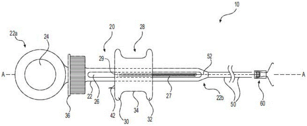
As noted above, the single use device should be used for a single procedure to reduce or minimize the spread of disease and infection. The reused dispensing device may be improperly loaded with improperly configured or improperly sized dispensable instruments (e.g., tissue clips). Systems and devices according to exemplary embodiments of the present disclosure may be limited to preloaded dispensable instruments, e.g., the devices may not be reloaded for subsequent use. The dispensable instrument can be pre-loaded for a single procedure, e.g., multiple jaws can be dispensed for a tissue closure procedure. Referring to fig. 1, a medical device 10 (e.g., a device for dispensing an instrument such as a medical clip) is shown according to one embodiment. The medical device 10 includes: a handle 20; a conduit 50 connected to the handle 20; and one or more dispensable instruments 60 at the distal end of the catheter 50 opposite the handle 20 (e.g., for securing a grip of tissue).
With continued reference to FIG. 1, a handle 20 is shown. The handle 20 includes a body 22, the body 22 defining a bore 24 in the body 22 at a proximal end 22a thereof. The aperture 24 may be used to receive a thumb of a user of the device 10. The catheter 50 is attached at the opposite distal end 22b of the body 22. The slot 26 extends through the body 22 in a direction parallel to the longitudinal axis a of the conduit 50. The sleeve 28 includes a rod 29 disposed in the slot 26, and the rod 29 moves within the slot 26 and along the body 22 in a direction parallel to the longitudinal axis a. The spring 27 extends inside the slot 26 from the most distal end of the rod 29 to the most distal end of the slot 26. Spring 27 is biased to pull rod 29 and sleeve 28 distally to load the instrument as will be described herein. Wire 52 (or any other elongate actuator such as a cable, braided member, etc.) extends distally from the distal end of shaft 29 through catheter 50 to dispensable instrument 60. As will be described herein, actuation of the sleeve 28 in a proximal direction relative to the body 22 causes the wire 52 to actuate and release the dispensable instrument 60.
As further shown in fig. 1, the sleeve 28 includes two annular projections 30, 32 extending from the sleeve 28 at its distal and proximal ends, respectively, and in a direction perpendicular to the longitudinal axis a and the extension of the catheter 50. The annular projections 30, 32 define an annular grip 34 that is gripped by the user (e.g., with a middle finger and an index finger), as will be described in greater detail herein.
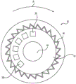
Referring to fig. 2, a ratchet 36 is circumferentially disposed on the body 22 between the bore 24 and the slot 26, proximal to the sleeve 28. A plurality of cavities 38 are circumferentially arrayed on the ratchet 36, each cavity being parallel to the longitudinal axis a and facing the distal end 22b of the handle 22 (it being understood that there may be a single cavity 38 shaped as a cavity 38n that would be useful for a single use medical device 10). According to one example, the medical device 10 includes six lumens 38, but is not limited to this number of lumens 38. The number of cavities 38 may be limited by the number of dispensable instruments 60 dispensed with the medical device 10, e.g., any number of dispensable instruments 60 may be preloaded into the medical device 10 for a single procedure. As shown in fig. 2, the cavity 38 has a generally rectangular shape, but may be any shape suitable for accomplishing the ratcheting motion described herein. The ratchet 36 may also include a plurality of ridge-like protrusions 40 extending from the side surface, e.g., extending from the side surface circumferentially about and perpendicular to the longitudinal axis a. The protrusion 40 may provide a textured feel and/or may aid in the operability of the ratchet 36 by providing a location for the user to grip. The ratchet 36 is rotatable relative to the body 22 about an axis a.
Referring to fig. 3, the tab 42 extends in a proximal direction from the proximal-most annular tab 30 of the sleeve 28. The walls of the projections 42 are inclined with respect to the axis a, for example having a beveled shape, and are sized and shaped to be received inside the cavity 38. As will be discussed in greater detail below, the tab 42 interacts with the cavity 38 and operates the ratchet 36, e.g., rotates about the body 22 in the direction indicated by arrow R (clockwise in the view of fig. 2).
The ratchet 36 and cavity 38 are shown in greater detail in fig. 4 and 5A-5C. Referring to fig. 4, the distal end of the ratchet 36 is shown and includes a distal face 41 defining the cavity 38. A through bore 44 extends from the distal end of the ratchet 36 to the proximal end thereof. The body 22 extends through the through bore 44 and allows the ratchet 36 to rotate about the body 22. The teeth 46 are disposed on a circumferential inner surface of the ratchet 36, between the proximal and distal ends of the ratchet 36, and are inclined (angled) relative to the direction of rotation (e.g., as indicated by arrow R in fig. 2 and 3). The teeth 46 prevent the ratchet wheel 36 from rotating in a direction opposite to the direction of rotation R by gripping a stop (not shown) of the handle 20. The stop will engage the teeth 46 as the ratchet 36 rotates, allowing the ratchet 36 to rotate to the next one of the plurality of cavities 38 and preventing reverse rotation.
Referring to fig. 5A-5C, side views of the ratchet 36 with cavity 38 are shown. As shown in fig. 5A, the cavity 38 includes a slope 39, the slope 38 being on one side of the cavity 38 in the rotational direction R. The ramp 39a is inclined relative to the axis a so that the distally facing inner wall 39c of the cavity 38 is smaller than the opening to the cavity 38. Fig. 5B shows a tab 42 on the sleeve 28. The tab 42 may be inserted into the individual cavity 38 and slid along the ramp 39a, thereby causing the ratchet wheel 36 to rotate about the handle 20 in the rotational direction R. When this occurs, the teeth 46 disengage from the stop in the body 22 and the adjacent tooth 46 engages the stop. The extreme tip portion of the projection 42 may have an inclined surface 42a having a slope similar to that of the slope 39a, thereby assisting the ratchet 36 in rotating in the rotational direction R. The tab 42 includes a flange portion 42b extending from a wall 42c of the tab 42 in a direction opposite the rotational direction R. When the instrument 60 is deployed, the projections 42 may engage each cavity 38 sequentially or individually until the projections 42 enter the last cavity 38 n.
As shown in fig. 5C, the last cavity 38n of the plurality of cavities 38 is shaped differently from the other cavities 38. The tab 42 can slide along the last cavity 38n of the ramp 39 a. The flange portion 42b of the tab 42 may interact with a surface 39b of the final cavity 38n that is generally perpendicular to the insertion direction of the tab 42. For example, flange portion 42b engages surface 39b to prevent tab 42 and sleeve 28 from moving distally, thereby locking ratchet 36 and sleeve 28 together.
Referring to fig. 6, a dispensable instrument 60 is shown. According to one embodiment, the instrument 60 is a tissue clamp for clamping tissues together. However, it should be understood that the instrument 60 is not limited to this configuration and may include any tool, device, or material that may be dispensed into a patient, such as any multi-use instrument for single patient use, including but not limited to a snare, a grasper, a biopsy forceps, etc., thereby preventing the multi-use instrument from being used in multiple patients. According to one example, the instrument 60 includes a body 66 at the proximal end of the instrument 60. A pair of jaws, hooks or tines 62, 64 extend distally from the body 66, and the hooks 62, 64 include proximal and distal ends 62a, 62b, 64a, 64b, respectively. The instrument 60 may be attached to the distal end of the wire 52 by a connection between the distal element 52a and the proximal ends 62a, 64a of the wire 52. According to one embodiment, the distal end 52a must travel beyond the distal-most end of the catheter 50 by at least a predetermined distance D to load the instrument 60 onto the medical device 10. For example, the predetermined distance D is the distance required for the distal end 52a to extend beyond the distal-most end of the catheter 50 into the proximal end of the body 66 and engage or grip the proximal ends 62a, 64a of the hooks 62, 64. As will be described in greater detail herein, once the instrument 60 is loaded onto the distal end 52a, the instrument 60 can grasp tissue by pulling proximally on the sleeve 28, thereby causing the wire 52, distal end 52a, and proximal ends 62a, 64a to travel proximally. When the proximal ends 62a, 64a are pulled proximally toward the body 66, the distal ends 62b, 64b approach one another and close on tissue (not shown) therebetween. When the distal inner surface 66a of the body 66 engages the outer surface of the walls 62, 64, the distal ends 62b, 64b are closed together as the walls 62, 64 are pulled into the body 66. Once the proximal ends 62a, 64a are pulled proximally a sufficient amount, the proximal ends 62a, 64a will separate and release the distal end 52a to release the instrument 60 from the medical device 10. In some embodiments, the walls 62, 64 may be biased in the closed configuration, although in other embodiments, the arms 62, 64 may be biased in the open configuration.
A method of operating the medical device 10 will now be described with reference to fig. 7. Referring to step 700, the distal end of the medical device 10 (including dispensable instrument 60) is introduced into a patient and advanced to a desired location. The desired position may be, for example, a position for a dispensing instrument 60, such as a clip for connecting two or more adjacent tissues together (see, e.g., fig. 6). Once the instrument 60 is in the desired position, the instrument 60 is placed in step 710. In step 710, the user grasps the sleeve 28 around the looped grip 34 and the user pulls the sleeve 28 proximally relative to the main body 22 to deploy the instrument 60. When the sleeve 28 reaches the proximal-most end of the slot 26, the tab 42 enters a first cavity 38 of the plurality of cavities 38. In step 720, if the user wishes to load another dispensable instrument 60, the user pushes the sleeve 28 distally. In step 730, a determination is made as to whether the sleeve 28 has actually moved distally and whether the tab 42 has exited the cavity 38. If the sleeve 28 is moved distally, the tab 42 leaves the cavity 38 and causes the ratchet 36 to rotate about the body 22. Another instrument 60 is then loaded onto the wire 52 in step 740. According to one example, the ratchet 36 rotates about the body 22 of the handle 20 in the direction of arrow R (e.g., in a clockwise direction). However, in another embodiment, if the cavity 38 and the teeth 46 are arranged differently, the ratchet 36 may rotate counterclockwise around the body 22. Once the tab 42 exits the cavity 38, the sleeve 28 may again be pushed distally in step 710 to deploy the next instrument 60. However, it should be understood that if the surgeon does not have further need to deploy the instrument 60, the deployment of the instrument 60 is terminated. If it is determined in step 730 that the sleeve 28 is not moving distally, the sleeve 28 is locked in place by the interaction of the tab 42 with the cavity 38n in step 750 so that no additional instrument 60 will be loaded onto the distal end 52a of the wire 52. Locking the sleeve 28 relative to the ratchet 36 prevents reuse of the medical device 10 once all of the instruments 60 have been delivered.
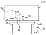
In another embodiment, a medical device 110 is shown in fig. 8A-8C. The medical device 110 includes similar features as the medical device 10, including a catheter 50 and an instrument 60 attachable to a distal end thereof. A handle 120 is attached to the proximal end of the catheter 50. The handle 120 includes some features similar to those of the handle 20 and these features are identified with similar reference numerals. The handle 120 also includes a tube 121, the tube 121 defining a chamber 122 adjacent to the body 22 and parallel to the body 22. The chamber 122 typically extends the same distance or substantially the same distance as the slot 26, but is not limited to this dimension. The chamber 122 includes a plurality of spherical balls 124 (it should be understood that there may be a single chamber spherical ball 124 that would be useful for the single use medical device 110). According to one example, the medical device 110 includes six spherical balls 124, but is not limited to this number of spherical balls. The number of ball balls may be limited by the number of dispensable instruments 60 dispensed with the medical device 110. Tube 121 includes a retaining device 126, and a magnet 125 disposed at the distal end of chamber 122. As will be described in more detail, the spherical balls 124 are initially disposed at the proximal end of the chamber 122 and are held in place by a retaining device 126, which retaining device 126 may be a portion of the wall of the tube 121 having an inner diameter that is smaller than the remainder of the tube wall 121, so that the wall 121 imparts friction to the balls 124. This force helps to hold the ball 124 in place until subjected to sufficient force to overcome the frictional force, thereby allowing release of the ball 124. The spherical balls 124 may be any material that is magnetic for reasons set forth below. It should also be understood that only a portion of ball 124 (e.g., the center or cover of ball 124) may include magnetic material and/or ball 124 may be any other shape.
With continued reference to fig. 8A-8C, a sleeve 128 surrounds the periphery of the handle 120 and the chamber 122. Sleeve 128 includes a securing member 130 (similar to rod 29 in fig. 2) slidably received in slot 26, which allows sleeve 128 to slide proximally and distally along handle 120 and chamber 122. According to one example, the proximal-most end of the wire 52 is attached to the fixation member 130. However, it should be understood that the wire 52 may be attached to another portion of the sleeve 128. The sleeve also includes a sleeve chamber 132 slidably received in the chamber 122. As shown in fig. 8A, the proximal end of the sleeve chamber 132 includes a tapered wall 136 such that the chamber 132 has a smaller inner diameter at the proximal taper. The tapered portion of the wall 136 may be flexible to allow entry of the ball 124 when sufficient force is applied to the ball 124. The distal end of the sleeve chamber 132 includes a one-way gate 134, the one-way gate 134 being rotatable about a gate axis G, as indicated by arrow O in fig. 8A. While the door axis G is illustrated adjacent the body 22 of the handle 120, it should be understood that the door axis G is not limited to this location and may be located, for example, on the outermost edge of the chamber 122. The gate 134 may be a magnet and/or may include a magnet to attract the ball 124. The strength of the magnet on the door 134 or in the door 134 is less than the strength of the magnet 125.
Similar to handle 20, sleeve 128 of handle 120 dispenses an instrument 60 when pulled in a proximal direction and loads the next instrument 60 when pushed in a distal direction. As the sleeve 128 approaches the proximal end of the handle 120, the magnetic gate 134 attracts the most distal ball-shaped ball 124a and allows the most distal ball-shaped ball 124a to enter the sleeve chamber 132. The magnetic force overcomes the frictional force holding the ball 124 in the chamber 122 and applies sufficient force to overcome any force applied by the tapered wall 136. When the sleeve 128 is located at the distal end of the handle 120, the magnetic force attracts the ball 124a toward the magnet 125, causing the door 134 to rotate about the door axis G to open (as shown in fig. 8C) and place the ball 124 at the magnet 125. If the door 134 is magnetized, the magnet 125 has a magnetic force sufficient to overcome the magnetic force of the door 134. In the absence of the door 134 being seated with the ball 124, the proximal movement of the sleeve 128 allows the door 134 to close. As will be explained in detail below, the ball balls 124 may be moved sequentially or individually from the proximal end of the chamber 122 to the distal end of the chamber 122. The magnet 125 has sufficient magnetic force to pull the last ball 124n past the gate 134. Once all of the balls 124-124 n have been placed at the distal end of the chamber 122, the sleeve 128 cannot be advanced distally sufficiently to allow loading of another dispensable instrument 60 (e.g., a clamp), e.g., the ball balls 124 act as spacers to prevent subsequent placement of another instrument 60.
The method of operation of the medical device 110 shown in fig. 8A-8C will now be described. In step 900, the distal end of the medical device 110 (including the instrument 60) is introduced into the patient and advanced to a desired location. As with the method described in fig. 7, the desired position may be, for example, a position for a dispensing instrument 60 (e.g., a clip) for connecting two or more adjacent tissues together. Once the instrument 60 is in the desired position, the instrument 60 is deployed. In step 910, the user grasps the sleeve 128 about the looped grip 34 and the user pulls the sleeve 128 proximally to deploy the instrument 60. In step 920, when the sleeve 128 reaches the proximal end of the handle 120, the distal-most ball 124a enters the sleeve chamber 132. As described above, the ball 124a is disposed in the sleeve chamber 132 and magnetically attracted to the proximal side of the gate 134. In step 930, the user pushes the sleeve 128 distally to begin the process of loading another dispensable instrument 60. In step 940, it is determined whether sleeve 128 has moved distally at least a distance D to load the next instrument 60 onto wire 52. If sleeve 128 is moved a distance D in the distal direction, the next instrument 60 is loaded onto distal end 52a of wire 52 in step 950. However, if the ball 124n has been placed at the distal end of the chamber 122 last, the sleeve 128 will not move a sufficient distance to load the instrument 60 and it will be determined in step 960 that the medical device 110 is not able to receive another instrument 60, thereby preventing reuse of the medical device 110.
It should be understood that the handle 20 and other components of the medical device 10, 110 may be made of any material known in the art, including, but not limited to, medical grade plastics or rubbers, ceramics, metals, or combinations thereof.
It will be apparent to those skilled in the art that various modifications and variations can be made in the disclosed apparatus without departing from the scope of the disclosure. For example, the medical device may be used to dispense medical clips or other similar devices and/or prevent their loading. Other embodiments of the disclosure will be apparent to those skilled in the art from consideration of the specification and practice of the invention disclosed herein. It is intended that the specification and examples be considered as exemplary only, with a true scope and spirit of the invention being indicated by the following claims.