CN1140228C - Mechanical prosthetic valve, and methods of its construction and operation - Google Patents
Mechanical prosthetic valve, and methods of its construction and operation Download PDFInfo
- Publication number
- CN1140228C CN1140228C CNB971984921A CN97198492A CN1140228C CN 1140228 C CN1140228 C CN 1140228C CN B971984921 A CNB971984921 A CN B971984921A CN 97198492 A CN97198492 A CN 97198492A CN 1140228 C CN1140228 C CN 1140228C
- Authority
- CN
- China
- Prior art keywords
- mentioned
- blade
- pair
- valve
- valve leaflets
- Prior art date
- Legal status (The legal status is an assumption and is not a legal conclusion. Google has not performed a legal analysis and makes no representation as to the accuracy of the status listed.)
- Expired - Fee Related
Links
Images


Classifications
-
- A—HUMAN NECESSITIES
- A61—MEDICAL OR VETERINARY SCIENCE; HYGIENE
- A61F—FILTERS IMPLANTABLE INTO BLOOD VESSELS; PROSTHESES; DEVICES PROVIDING PATENCY TO, OR PREVENTING COLLAPSING OF, TUBULAR STRUCTURES OF THE BODY, e.g. STENTS; ORTHOPAEDIC, NURSING OR CONTRACEPTIVE DEVICES; FOMENTATION; TREATMENT OR PROTECTION OF EYES OR EARS; BANDAGES, DRESSINGS OR ABSORBENT PADS; FIRST-AID KITS
- A61F2/00—Filters implantable into blood vessels; Prostheses, i.e. artificial substitutes or replacements for parts of the body; Appliances for connecting them with the body; Devices providing patency to, or preventing collapsing of, tubular structures of the body, e.g. stents
- A61F2/02—Prostheses implantable into the body
- A61F2/24—Heart valves ; Vascular valves, e.g. venous valves; Heart implants, e.g. passive devices for improving the function of the native valve or the heart muscle; Transmyocardial revascularisation [TMR] devices; Valves implantable in the body
- A61F2/2403—Heart valves ; Vascular valves, e.g. venous valves; Heart implants, e.g. passive devices for improving the function of the native valve or the heart muscle; Transmyocardial revascularisation [TMR] devices; Valves implantable in the body with pivoting rigid closure members
Abstract
A prosthetic mechanical valve includes a base portion defining a through blood flow pathway closed by at least a pair of valve leaflets. The valve leaflets are pivotally carried by the base portion and movable in response to dynamic blood fluid pressures between a first position at which the leaflets close blood flow through the pathway and a second open position allowing blood flow in the pathway. A pair of confronting magnets are carried one to each of the pair of valve leaflets and attract one another. The magnetic forces of attraction between the pair of magnets imparts a biasing torque to the valve leaflets which tends to synchronize pivotal movements of the leaflets, cushions their sealing contact, quiets valve operation, and biases the leaflets toward a third partially open position. As a result, under conditions of nearly balanced blood fluid pressures across the pair of valve leaflet they anticipatorily open toward their third position to improve pumping effectiveness. Also, at about the end of a blood pumping stroke, the valve leaflets anticipatorily close from their fully open position toward the third position to reduce regurgitation flow and quiet the valve.
Description
Background of invention
Invention field
The present invention relates to the field of the mechanical prosthetic replacement valve of implant into body.The present invention is specifically related to replace natural valvular mechanical heart valve, and this valve comprises base part, and this base part can be fixed on the tissue of heart of patient.This valve comprises the base part that defines the blood channel that runs through.This blood channel can be closed by active valve assemblies, and this valve assemblies has at least one pair of valve leaflets that can move between the primary importance and the second position.Be fitted to each other and cooperate with base part and close blood channel in the primary importance valve leaflets.Blade can forward the position of opening fully to, and at this moment, blade rotation is left the state that is sealed and matched each other, enter one near with channel axis to the collimation the position, Open from This Side, makes the blood flow mistake.This blade is associated with each other, and can yieldly the blade offset column be positioned at the 3rd turned position that open intermediary part, first and second positions.
Relevant technologies
The St.Jude Medical in St.Paul city, the Minnesota State, the U.S. Patent No. 4 276 658 that Inc company proposed on July 7th, 1981 discloses a kind of cardiac valve, everybody be called " St.Paul (Sao Paulo) valve ".This mechanical heart valve comprises base part, and this base part forms the blood channel that runs through and supports a pair of valve leaflets rotationally.This valve leaflet is fitted to each other and cooperates with base part and can close blood channel hermetically.In addition, the active force that blade can also the response power blood flow forwards another to and allows blood flow through the position of blood channel along a direction.The active force of this power blood flow can make blade open and close between the position at it and rotate, so that by the heart of patient wriggling ground pump blood that valve is housed.
A shortcoming of Sao Paulo valve that people generally acknowledge is, that works opens to meet the pump stroke of heart unlike natural valve for blade.That is, natural valve can respond the valve both sides blood flow pressure balance and open a little.This natural valve is opened under equalizing pressure in advance can be better and be full of ventricle more completely.Lack the pumping efficiency that Sao Paulo valve that this pressure balance of going ahead of the rest opens has considerably reduced heart.
The generally acknowledged shortcoming of another of Sao Paulo valve is that blade can not close and begin to close to meet the end of heart pump stroke.As a result, the backflow of blood may take place, so that begin to close and close valve fully.Because valve leaflets is opened fully when this backflow takes place, thus blade can be from the position of opening fully bang once shut.Therefore this blade is moving to its closed position from its open position, makes to each other and when being sealed and matched with base member, cause to each other and with the strong impact of base member.This ballistic result when valve closing has greatly accelerated the undesirable valve rate of wear and has caused the impact noise that does not need.Can outside the patient body, hear this undesirable impact noise in general, sound like and cough up the sound of rattling away.Although some patient feels this noise of rattling away of coughing up, and listen comfortablely, the new prosthetic heart valve work of this expression gets fine, and at one's side some of other patient and patient hear that this operation is coughed up and then feel uncomfortable when rattling away and take sb's mind off sth easily.
The conventional mechanical cardiac valve that should be noted that Sao Paulo type has demonstrated its valve leaflets asymmetric and/or nonsynchronous motion to each other.That is, the valvular valve leaflets of conventional mechanical always can not be rotated with being mutually symmetrical or be rotated synchronously with one another.And this asymmetric or asynchronous motion has increased the impact of closing of trailing a valve leaflets.
A kind of way of opening of going ahead of the rest for these wearing and tearing, noise and the shortage that solve Sao Paulo type valve is proposed in the U.S. Patent No. 4 605 408 that proposes its on August 12nd, 1986 by Alain Carpentier.According to the explanation of ' 408 patent, perhaps, it is moved to open position with a leaf spring arrangement that works when its valve seat at blade or with the blade of a pair of magnet bias voltage mechanical heart valve that repels each other.A magnet in the every pair of magnet is illustrated and is contained on the blade, and another magnet of every centering then is contained near on the base component of valve seat.Magnet is oriented to each other to repel each other.As a result, can promote valve leaflets and leave its valve seat.When blade during near its valve seat, a kind of buffering of closing of the biasing force shape of this effect also promotes blade simultaneously and leaves its valve seat, and in advance opening of valve is provided.
Unfortunately, ' 408 patents are implemented in safety and effective mechanical heart valve till the ass ascends the ladder.Because spring may rupture and disruptive spring becomes a kind of ectosome in cyclic system disorder of internal organs motion, do not adopted till now so have the embodiment of leaf spring.Use is supported the embodiment of relative magnet also not in commercial enforcement, because there is various problem in this design by blade and base component.A problem is, is used for configurations of magnets at the too restricted and magnet of the actual size of can not packing into of the available physical space in the blade edge portion (magnet must be configured on this marginal portion so that facing to the magnet on the base portion).Another problem is magnet to be positioned at the big zone of contact stress, and this has quickened the fatigue problem of valve structure.
Provide another to solve the recommend method of conventional mechanical prosthetic heart valve defective in the U.S. Patent No. 5,123 918 that Philippe Peerrier equals to propose on June 23rd, 1992.According to the explanation of ' 918 patent, three blade prosthetic heart valves comprise the magnet that attracts each other that is contained in the blade corner.Attracting each other of this blade is opposite with opening of blade in advance, because Magnet attracts each other, tends to magnet is locked in the closed position.At the open position of valve, the magnet face of blade facing to be contained in the valve base part to straight locational same polarity magnet.Therefore these magnets will repel mutually, push blade to closed position.In other words, valve leaflets will be subjected to radially inner promotion, away from base part, provide in advance closing of blade.
Yet ' 918 patent this gone ahead of the rest closes only is owing to apply bias voltage from the fully open position of valve to the closed position.Because valve leaflets magnetic attraction each other, this valve is also pushed to its closed position by magnetic field.In this design, as if any biasing force does not appear, with valve leaflets from its closed position push to one close and the fully open position between the position of opening, the part of dynamic stability.
Known another mechanical prosthetic heart valve in the communique No.0023797A1 of EUROPEAN PATENT OFFICE.This communique is considered to disclose a kind of mechanical prosthetic heart valve, and in this valve, this valve leaflets can be rotated and translation simultaneously when blade moves between its opening and closing position.Can not think that this valve provides opening in advance or closing in advance of valve leaflets.As if without any flexible bias pressure valve leaflets is turned to specific position of valve.
In view of above explanation, be sought after providing a kind of cardiac valve of machinery, this valve can be avoided one or more defectives of common process.
Particularly need to provide a kind of mechanical heart valve, this valve blade be in contact with one another when contacting with the base component of valve can buffering blade closing movement.
If valve have in advance pressure balanced opening function and one for the biasing force that makes valve leaflets simultaneously operating then can realize this mechanical heart valve another need feature.
The gimp that can reduce valve effectively as the cushioning effect when closing valve then can realize a feature again of this mechanical heart valve.
The feature of additional requirement is to make blade flexibly push in advance closed position to, make blade not can because of the backflow effect from its position of opening fully bang be closed for one.
In addition, the feature of the needs of this prosthetic heart valve is to apply biasing force to valve, make its not only can but also can shift to from its closed position from its position of opening fully intermediary part that open with position dynamic stability.Opening in advance but also provide in advance and closing of valve not only was provided this feature.
Another feature that needs is that prosthetic heart valve has this blade, and promptly this blade can open and close at it and carry out symmetric between position or be synchronous rotation at least.
Brief summary of the invention
Owing to the above, the objective of the invention is to overcome one or more defectives of routine techniques.
Another object of the present invention provides a kind of mechanical heart valve that can the buffering blade closing movement.
A further object of the present invention provides a kind of mechanical heart valve, and this valve has pressure balance opening function and reaches the biasing force of simultaneously operating in advance.
Another purpose of the present invention provides a kind of cushioning effect when valve is closed, and this cushioning effect can reduce the gimp and the wearing and tearing of valve effectively.
In addition, the purpose of this invention is to provide a kind of mechanical heart valve, blade can be yieldly from the position that the location bias of opening is fully opened to a part in this valve, makes the open position that surpasses this part open position of blade just be subjected to flowing through the control of the blood flow velocity of valve.
Therefore the invention provides a kind of mechanical prosthetic valve of implant into body, this valve comprises: the base part that defines channel of blood flow; A pair of valve leaflets, this blade is configured in the channel of blood flow rotationally, and response blood flow pressure and can between the turned position that primary importance and second is opened fully, rotating, this blade cooperates to each other and with base part formation sealing in primary importance, thereby stop blood flow to cross passage, make blood flow cross passage in the second position; A kind of mechanism is used for being positioned at intermediary the 3rd turned position, the first and second turned positions above-mentioned a pair of valve leaflets of can setovering yieldly from the second position to one again from primary importance.
According to a further aspect, the invention provides a kind of method of manufacturing machine prosthetic heart valve, this method comprises the steps: to provide the base part that defines channel of blood flow; The valve leaflets of a pair of fluid-responsive pressure is provided; A pair of valve leaflets is configured in the channel of blood flow, and make a pair of paddle response blood flow pressure and between the primary importance and the second position opened fully, rotate, cooperatively interact and cooperate hermetically with base part and stop blood flow to cross passage at this blade of primary importance, in the second position, blade is opened, and allows blood flow cross passage; The a pair of valve leaflets of can setovering yieldly is to the 3rd position that is positioned at the intermediary dynamic stability in first and second positions.
Another aspect of the present invention provides a kind of method of operating the mechanical prosthetic valve that combines with heart, and this heart provides the blood flow of pulsation during pump stroke, and this valve comprises: the base part that defines blood channel; The valve leaflets of a pair of fluid-responsive pressure, this blade is configured in the channel of blood flow rotationally, and response blood flow pressure and between the primary importance and the second position opened fully, rotating, in primary importance, a pair of valve leaflets cooperates hermetically mutually and cooperates hermetically with base part, crosses passage to stop blood flow, and in second turned position, this valve leaflets is rotated away to each other and with being sealed and matched of pedestal, thereby make blood flow cross passage; This method may further comprise the steps: a pair of valve leaflets to of can setovering yieldly is positioned at the 3rd turned position of the intermediary dynamic stability in first and second positions; Use this biasing that can surrender and make that formation is from the second position this closing valve leaflets to the 3rd position in advance when pump stroke finishes substantially.
Another aspect of the present invention provides a kind of mechanical prosthetic heart valve, comprising:
Limit the circular base part of channel of blood flow; The a pair of piece that constitutes by magnetic material; At least one pair of valve leaflets, this blade is configured in the channel of blood flow rotationally, and can respond blood flow pressure respectively and between first turned position and second turned position, rotate around the corresponding pivot line, in primary importance, this reciprocally and with base part cooperates hermetically to blade, to stop blood to flow at first direction, and in the second position, valve leaflets separately, blood is flow through along opposite second direction, this carries in the pair of magnetic piece corresponding one to each blade in the valve leaflets, its pole configuration of in the pair of magnetic piece at least one is shaped as a kind of magnetic line of force, this magnetic line of force connects the pair of magnetic piece in the mode of attracting each other, this separates each magnetic block in the magnetic block and the respective pivot line that carries the valve leaflets of each magnetic block, so that can be when valve leaflets is rotated along corresponding arc swing, this corresponding arc is juxtaposed, thereby each valve leaflets of a centering can on the magnetic influence and apply a moment on another blade, thereby make this valve leaflets is displaced to the 3rd turned position that is positioned at the intermediary dynamic stability in first and second positions synergistically.
Below in conjunction with the appended accompanying drawing of this paper, read the detailed description of two exemplary embodiments of the present invention and just can obviously find out attached purpose of the present invention and advantage, in the accompanying drawings, the identical numbering of whole employing is represented identical parts or similar parts on 26S Proteasome Structure and Function.
Brief description of drawings
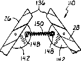
Fig. 1 is the plane graph that embodies mechanical heart valve of the present invention, is the plane graph of looking from the valve downstream, and the valve assemblies of closing of this valve is positioned at the closed position;
Fig. 2 is the plane graph that is similar to Fig. 1, but the valve assemblies of closing of valve is positioned at the position of opening fully;
Fig. 3 is that the valve assemblies that illustrates is positioned at (also being that the part is closed) centre position of opening the part along the mode cross section figure of the 3-3 line of Fig. 1 intercepting, and the position of opening fully that is positioned at the valve as shown in Figure 2 that with dashed lines shows;
Fig. 3 a is local some schematic cross-sectional view that amplifies, and the part of Fig. 3 and the valve leaflets of valve is shown is positioned at its middle position;
Fig. 4 is the perspective view that is used in the single valve leaflets in the valve shown in Fig. 1-3;
Fig. 5 is some the schematic cross-sectional view that is similar to the amplification of Fig. 3 a, and second alternate embodiment of the present invention is shown;
Fig. 6 is the perspective view that is used in the single valve leaflets in the valve shown in Figure 5;
Fig. 7 is the vectogram of power, and the operational circumstances of the alternate embodiment of the present invention shown in Fig. 5 and 6 is shown;
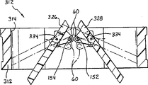
Fig. 8 is the plane graph that embodies the mechanical heart valve of the 3rd alternate embodiment of the present invention, is the plane graph of looking from the upstream side of valve, and the valve assemblies of closing of valve is positioned at the closed position among the figure;
Fig. 9 is the plane graph of similar Fig. 8, but the valve assemblies of closing of valve is positioned at the position of opening fully;
Figure 10 is that the open position as shown in Figure 9 of valve is shown in broken lines along the cross-sectional view of the 10-10 line intercepting of Fig. 8;
Figure 10 a is the partial cross section view that is similar to Figure 10, but the valve leaflets that is in asynchronous motion of valve is shown;
Figure 11 is the perspective view that is used in the single valve leaflets in the valve shown in Fig. 8-10a;
Figure 12-the 14th, the similar amplification schematic cross section of Fig. 8-11 illustrated embodiment is illustrated in the valve leaflets of different operating position;
Figure 15 is the partial cross section view of amplifying, and the 4th alternate embodiment of mechanical prosthetic valve is shown;
Figure 16 is the perspective view that is used in the single valve leaflets on embodiment illustrated in fig. 15;
Figure 17 is a partial cross section view, and the 5th alternate embodiment that embodies mechanical prosthetic valve of the present invention is shown, and among the figure, closes valve assemblies and is positioned at the closed position;
Figure 18 is the partial cross section view of mechanical prosthetic valve the 5th alternate embodiment shown in Figure 17, among the figure, closes valve assemblies and is positioned at the centre position;
Figure 19 is the partial cross section view of the 5th alternate embodiment of mechanical prosthetic valve shown in Figure 17 and 18, among the figure, closes valve assemblies and is positioned at the position of opening fully;
Figure 20 is the perspective view that is used in the single valve leaflets in Figure 17-19 illustrated embodiment;
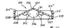
Figure 21 is the plane graph that is similar to Fig. 1, and the 6th alternate embodiment of implementing mechanical prosthetic valve of the present invention is shown;
Figure 22 is the sectional view that is similar to Fig. 3, and the embodiment of Figure 21 is shown, and is the sectional view along the intercepting of the transversal shown in the arrow 22-22 of Fig. 3;
Figure 23 is the perspective view that is used in the single valve leaflets in Figure 21 and 22 illustrated embodiments.
The some exemplary DETAILED DESCRIPTION OF THE PREFERRED of invention
With reference to figure 1-4,, implement mechanical heart valve 10 of the present invention shown in the figure simultaneously at first with reference to figure 1.Exemplary cardiac valve 10 comprises piped base part 12, and this base part 12 forms the channel of blood flow 14 that runs through, and makes blood flow through this passage along the single direction shown in the arrow 16 of Fig. 3.Channel of blood flow 14 generally is columnar on plane graph, as illustrated in fig. 1 and 2.This columnar channel of blood flow 14 comprises circular portion 14 ' and a pair of relative surface 14 of extending vertically ".
In order externally to provide a kind of method to make the surgeon valve 10 can be fixed on the heart tissue, base part forms annular groove 18 between a pair of isolated outwardly directed projecting part 20 and 20 ', fiber suture ring (not shown) can be fixed in this annular groove.Know that as those skilled in the pertinent art the doctor can be sewn to valve on the heart or other tissue of patient with this suture ring.The technical staff is appreciated that valve of the present invention is equally applicable to mechanical heart and heart-assist device, and in this case, basic Cuo part 12 can not directly be fixed on the heart tissue.Therefore, the external structure of base part 12 is exemplary, can not think limitation of the present invention.
Each surface 14 at base part 12 " on define the groove 22 and 24 of a pair of isolated butterfly shape.Groove 22 and 24 cross section are semicircular.Being contained in rotationally in this a pair of groove is a pair of corresponding valve leaflets 26 and 28, and each blade is roughly D shape.On each valve leaflets 26 and 28 opposed end, form the corresponding protuberance in a pair of relative semicircle protuberance 30 and 32.For installing rotationally and keep this a pair of valve leaflets 26 and 28, each blade 26 and a protuberance in 28 the relative protuberance 30,32 are contained in the groove in the groove 22,24 rotationally.In groove 22,24, form the respective pivot 34 of each indivedual blades in the valve leaflets on the rotatable protuberance of installing 30 and 32.Base part 12 and valve leaflets 26,28 are generally made of nonmagnetic substance.For example, base part 12 can be made of RESEARCH OF PYROCARBON. Valve leaflets 26 and 28 can be made of titanium.No matter be that base part 12 or valve leaflets 26,28 all can be used other material.Yet under various feelings, be used to make the base part of valve 10 and the material of valve leaflets is a nonmagnetic substance.
As shown in Figure 1 and as the technical staff of relevant technology understand, when the respective straight edge 36 of blade 26,28 turns to primary importance toward each other, this edge 36 cooperates each other hermetically.In addition, the corresponding curved edge 38 facing to edge 36 of each blade 26,28 cooperates interior cylindrical surface part 14 ' hermetically when its primary importance, and this surface portion is formed by base part 12, is the part of channel of blood flow.Blade 26 and 28 along plane surface part 14 " part form corresponding flat lateral edge portions 40 respectively, this marginal portion can form the tight fit of sealing with plane surface 14, and from then on protuberance 30,32 stretches out the marginal portion.In the primary importance of valve leaflets 26,28, can close or block basically blood flowing in contrast to the direction of direction shown in the arrow 16.
Yet, directly illustrate as Fig. 2 and as being shown in dotted line of Fig. 3, valve leaflets 26,28 moves to substantially (promptly parallel with the arrow 16) second position with the alignment of axe of channel of blood flow 14 respectively.Be appreciated that the dynamic pressure that blade 26 and 28 can respond blood flow moves between the primary importance (closing) and the second position (opening fully).Should be noted that blade 26,28 in this implements as can not rotating independently of one another of below will illustrating.That is, for synchronous and rotation symmetrically, blade the 26, the 28th, intermeshing.
In addition, be bonded to each other and can see with reference to figure 3,3a and 4, the downside of each valve leaflets (promptly facing to the downstream of watching the people) comprises a pair of isolated semicircle targeting part 42.Can see that these targeting parts 42 protrude from each valve leaflets,, form a lever arm that can between valve leaflets, apply moment facing to adjacent vanes.These targeting parts comprise corresponding guide edge surface 44 respectively, and these surfaces are facing to the similar guide edge part 42 and the surface 44 of another valve leaflets.To the small part ring surface, should be formed the fan-shaped part 46 of gear teeth in surface 44 at each guide edge surface ring surface.But be meshing with each other to fan-shaped part 46 transmissions of gear teeth of two valve leaflets 26,28 on each targeting part 42.As a result, blade 26,28 is by fan-shaped part 46 transmissions simultaneously of targeting part 42 and gear teeth, thereby can rotate symmetrically and synchronously between its first and second position, shown in Fig. 2 and 3 (dotted line).
Can see referring to Fig. 3 a, for the member that the bias voltage flexible member is connected in valve leaflets is provided, each targeting part 42 also comprises pin parts 48, and these parts 48 protrude and be in substantially parallel relationship to the respective pivot line 34 of valve leaflets 26,28 to another relative targeting part 42.The pivotal line 34 of pin 48 and blade from a distance, and with respect to the plane tilted configuration of blade, the inclination angle is represented with arrowed alphabetical α on Fig. 3 a.Shown in Fig. 3 and 3a, the bias voltage flexible member that is connected in blade is a tension force disc spring 50, and this disc spring is extending between pin 48 ends relatively.A stature (as shown in the figure) or a hook or other structure can be with in the end of this pin, so that can fixed engagement spring 50.Alternatively, each end of spring 50 can form an elbow and the end parts of hook is arranged, and direct and targeting part engagement for example is inserted into and remains in the respective aperture of passing targeting part.The those of ordinary skill of relevant technologies itself can propose many other feasible methods that spring or other elastomeric element are connected to blade.
Should keep in mind, blade 26,28 pivots in base part.Thereby, because pin 48 is a tilted configuration with respect to the primary importance (closing) and the second position (opening fully) of valve leaflets 26,28 (remembeing above-mentioned angle [alpha]), so the tension force of spring 50 (representing with arrow 50 ' on Fig. 3 a) is with the bias voltage blade, it is moved, shown in Fig. 3 a to intermediary the 3rd position, first and second positions.The 3rd turned position be valve leaflets 26,28 dynamic stability or " not acted on " position.In other words, hereinto between the position, pin 48 is substantially on the straight line that extends between the pivotal line 34. Valve leaflets 26,28 can be setovered yieldly to the centre position of its dynamic stability, uses the position of representing by the dotted line of these points as Fig. 3 a.Important also is appreciated that, the pin of each blade and targeting part form an effective lever arm, and the spring force of spring 50 can be with a moment loading on each blade by this arm, thereby makes the position that they turn to this not acted on." dynamic stability " both meaned and utilizes effective flexible bias pressure can stop that it (is that bias mechanism can be surrendered that valve leaflets leaves the disturbance of this position, allow to make valve close and open fully with abundant big power), mean that again this biasing force can make valve leaflets get back to the position that this is not acted on after disturbance.
Understand easily, when valve leaflets 26,28 was positioned at its complete closed position, the power of spring 50 trended towards opening blade, made it shift to the 3rd position (position that is not promptly acted on) that illustrates.Thereby can provide pressure balanced that blade goes ahead of the rest to open in advance, so just can improve the pumping efficiency of heart.That is, the blood pressure of closing the valve leaflets both sides arrives when equating basically, and blade will turn to the 3rd position from its closed position.In fact, the those of ordinary skill of relevant technologies will recognize that the pressure reduction in the blade both sides reached before zero actually, and the valve leaflets of closing will begin this opening of going ahead of the rest.This is because reduce and just have a moment near zero the time when the pressure reduction of closing the blade both sides, and quarter at this moment, the effective torque that acts on the blade that is caused by pressure reduction just in time acts on effective tensile force on the blade apart from counteracting by what spring 50 caused.Surpass this constantly, when the pressure reduction of blade both sides further reduces, blade will begin the rotational motion of opening that it goes ahead of the rest.
In addition, when blade was in its fully open position, spring 50 provided a biasing force, and this biasing force trends towards making blade to shift to the 3rd position from this position of opening fully.Thereby become blood stream pressure (being blood flow rate) in the position of the blade between fully open position and the 3rd position and act on the function of dynamic balance between the spring bias on the blade.When blood flow rate slowed down because of the afterbody near the heart contraction stroke, blade 26,28 was just shifted to the 3rd position from the position of opening fully.Subsequently when blood begins to reflux, blade is just near its closed position and switch quickly, this energy that only turns over less angle and only need less backflow blood of closing.Like this, compare the energy that has reduced blade gained when closing, also reduced the wearing and tearing and the noise of valve simultaneously with conventional valve.
Because blade when its 3rd position when resting on its fully open position more close closed position, because of face is to finish valve to close the distance of required motion shorter, also reduce blood simultaneously and reflux.Moreover when valve leaflets when the closed position is shifted in the 3rd position from its fully open position, spring bias becomes the power that blade is opened of trending towards.The blood return pressure has guaranteed that blade 26,28 closes really.But opposite spring bias makes the blade degradedness of just closing, thereby can cushion this closing, and further makes valve 10 become quiet.
Fig. 5 and 6 illustrates the alternate embodiments of valve of the present invention, motion when can guarantee valve in this embodiment, but not necessarily symmetric motion.In explanation during this alternate embodiment, for obtaining used numbering, in Fig. 5 and 6, identical with parts shown in Fig. 1~4 or on 26S Proteasome Structure and Function similar parts adopt above-mentioned identical numbering to represent, but increase numeral 100.
In combination with reference to figure 5 and 6, can see that each other the downside of each valve leaflets also comprises a pair of isolated semicircle targeting part 142.These targeting parts 142 protrude from blade respectively, facing to adjacent vanes, and comprise corresponding guide edge surface 144 respectively, and this surface is towards the similar guide edge surface of adjacent valve leaflets.Yet each guide edge surface 144 is slick semicircles, facing to but do not contact relative guide edge surface 144.In other words, there are not the transmission engagement fully in a valve leaflets and another blade on the positive drive meaning, with above-mentioned different fully with first embodiment that illustrate.
But it should be noted that each targeting part 142 comprises a pin 148, this pin protrudes and be roughly parallel to the respective pivot line 134 of valve leaflets 26,28 to another relative targeting part 142, and is just similar with first embodiment.Also be similar to first embodiment, tension force disc spring 150 extends between relative pin 148.This pin 148 is tilted configuration with respect to the primary importance (closed position) and the second position (fully open position) of valve leaflets 126,128, makes the tension force of spring 150 blade can be biased into and is positioned at intermediary neutral the 3rd position, first and second positions.
Therefore, blade 126,128 is subjected to fexible bias pressure and can be synchronized with the movement between its first and second position, but can not be forced to drive, and carries out symmetric rotation, and is different with first blade of implementing.With reference to figure 7, this illustrates the analysis chart of spring force, and this figure helps to explain that this flexible bias pressure can be used for making blade 126 and 128 to rotate synchronously.At the leaf position that illustrates, suppose that unbalanced blood flow pressure (representing that with arrow 16 different length of this arrow is represented different flowing velocities) is just making right hand blade open slightly largerly than left hand blade.
As a result, pin 148 will occupy illustrated position, and spring force (with arrow 150 ' expression) extends between pin 148.Find out that easily spring force trends towards making the left hand blade rotation, make straight line 148 ' collimation between the pivotal line 134 of spring force and pin 148 and left hand blade 126.In other words, spring force 150 ' trends towards making two pins 148 as close as possible, and this causes a pivot in pin 148 and the pivotal line 134 to trend towards aiming at straight line.Understand easily, when not having unbalanced moment on blade, two pins 148 will be along a straight line collimation that is parallel to pivot 34 lines.
Therefore find out that easily when valve leaflets 26,28 was in its fully open position, the power of spring 50 trended towards opening blade, make it shift to the 3rd position that illustrates.Therefore form opening in advance of blade, improved the pumping efficiency of heart.In addition, when blade was in its open position, spring 150 provided one to tend to make blade to shift to the biasing force of the 3rd position from its fully open position.Therefore in this second embodiment, blade also becomes blood stream pressure (blood flow rate) in the position between fully open position and the 3rd position and acts on the function of dynamic balance between the spring bias on the blade.Therefore blood flow rate is slack-off near heart contraction stroke terminal the time, thereby blade 126,128 is just shifted to the 3rd position from the fully open position;
Fig. 8,9,10,10a and 11 illustrations the 3rd embodiment of valve of the present invention, valve leaflets forms and to be synchronized with the movement but not necessarily to form symmetric motion in this embodiment.For obtaining that used Ref. No. in this alternate embodiment of the present invention is described, in Fig. 8~11, identical with parts shown in Fig. 1~7 or on 26S Proteasome Structure and Function the parts similar to it represent with above-mentioned identical numbering but increase numeral 200.
In combination with reference to figure 8~11, can see that each other the downside of each valve leaflets 226,228 comprises a pair of isolated semicircle targeting part 242.These guide parts comprise guide edge part surface 244 separately respectively, and these surfaces are facing to the similar guide edge part surface of another valve leaflets.Yet each guide edge surface 244 is level and smooth and is semicircle, towards relative guide edge surface 244, but is not in contact with it.In addition, a valve leaflets and another valve leaflets do not have the transmission engagement on the positive drive meaning, unlike above-mentioned first embodiment that illustrates and illustrate.This embodiment does not even comprise pin 148 and spring 150, and is different with above-mentioned second embodiment.Replace with flexible bias pressure and make blade forward the neutral position of valve leaflets 226,228 to, method is that a pair of permanent magnetism 52,54 is embedded in the surface 244 of targeting part 242. Permanent magnet 52,54 the most handy SmCo magnetic materials are made, and cover in the above with the covered portion (not shown) of blade 226,228, contact with magnetic material to prevent patient blood.
Can see also that in addition the effect of the elastic force of the spring 150 of above-mentioned second embodiment of its effect erect image of the magnetic attracting force between magnet 52,54 is the same.And Figure 10 a is the sketch map that is similar to Fig. 7, magnetic force is shown how promotes blade and rotate synchronously.That is, shown in Figure 10 a, if blade carries out asynchronous rotation, then the bias voltage magnetic attraction will trend towards making the blade of " front " slack-off between the blade, and the blade of " hysteresis " is quickened.With reference to figure 10a, if right hand blade is the blade of front, and the left hand blade is in to primary importance and rotates (promptly more close closed position), then magnet 52,54 each other not along the line by blade pivot center 234 or with the line collimation of this line parallel (be blade not the rotation-symmetric shown in Figure 10 and 12~14 concern).
Moreover, it is apparent that, not necessarily at aforesaid two location application magnets of magnet 52 and 54.Needed just one be magnet, and another is a magnetic.Permanent magnet still can attract the magnetic material of another parts (promptly 52 or 54), and valve still can be operated as described above.Below, 52 represent permanent magnet with numbering, and represent magnetic material with 54 that this magnetic material or permanent magnet perhaps are magnetic material purely.Of the present invention this provides very big safety for the embodiment that the permanent magnet that attracts each other with two kinds is made on the one hand.Just in case the ground of magnet part in magnet 52 or 54 or fully lose magnetic as a magnet then it remains a magnetic material, can attract another permanent magnet in the pair of magnets.Thereby valve will continue normal running and advantage of the present invention will be provided.
In addition, Figure 15 and 16 illustrates the 4th alternate embodiment of the present invention, in this embodiment, and with above-mentioned same numbering but increase similar parts on identical parts of 300 numeral or the 26S Proteasome Structure and Function.From Figure 15 and 16 as can be seen, valve leaflets 326 and 328 comprises a pair of isolated elongated protuberance 60 respectively in this embodiment, and the pivotal line 334 that this protuberance 60 is in substantially parallel relationship to blade extends.And these protuberances can be regarded as from a valve leaflets and protrude to another valve leaflets, and can see lever arm of formation as, make and moment can be applied on the corresponding blade.Bar-shaped permanent magnet 152,154 (or magnet 52, and another is equipped with a magnetic material is as described above) is housed on each protuberance 60.In this case, magnetic material 152,154 is general with pivotal line 334 collimations and be spaced from certain distance, rather than as the situation of above-mentioned enforcement, toward each other.In other words, the magnetic pole (representing with letter " N " and " S " in 16 at Figure 15) of magnet is positioned on the straight line parallel with pivot 334 substantially.As obviously seeing, if two substantially the same its magnetic pole orientation valve leaflets as shown in the figure are configured on as shown in figure 15 the position that cooperatively interacts, then the opposite utmost point of magnetic of permanent magnet 152,154 interconnects on the magnetic line of force.Under the situation of 154 usefulness magnetics (promptly not being magnet), then its position as the clavate part is important (rather than its polar orientation), and this technical staff to relevant technologies is conspicuous.
In addition, as shown in figure 15, the spacing of magnetic material 152,154 and pivotal line 334 forms lever arm, and these lever arms are with respect to valve leaflets 326,328 tilted configuration.Therefore the magnetic line of force of at least one magnetic in the magnetic 152,154 will link together between two blades (with dashed lines 60 ' is represented on Figure 15).In the position that is not acted on of blade, the magnetic line of force of this connection will extend along the connecting line between the pivotal line 334.As previously mentioned, first and second positions in blade 326 and 328, the magnetic line of force of blade connects can apply bias voltage to blade effectively, it is turned to be not subjected to the position that acts on, as shown in figure 15.
Figure 17~20 illustrate the 5th alternate embodiment of the present invention, and in this embodiment, the similar of valve can make blade rotate and translation between its closed position and fully open position in the structure of above-mentioned EP ' 797 bulletins.In addition, for obtaining that the used Ref. No. of this embodiment of the present invention is described, adopt above-mentioned identical numbering but increase 400 the numeral parts identical or parts similar on 26S Proteasome Structure and Function with it with the above-mentioned parts that illustrate.
Simultaneously with reference to 17~20, as we can see from the figure, valve 410 comprises base ring part 412, and this part 412 in this example forms grooves 422 and 424, and this groove is oval-shaped, and scatters to the downstream direction that blood flow is crossed valve.In addition, in this example, the protuberance 430,432 on valve leaflets 426,428 is a hemispherical, can slide and is contained in groove 422 and 424 rotationally.It is semicircular targeting part 442 that each blade 426 and 428 constitutes a pair of isolated part.A magnet in a pair of permanent magnet 452,454 that attracts mutually (or permanent magnet 452 and one and the opposed magnetic material that cooperates of permanent magnet, this material block is still represented with numbering 454 later on) is housed in each targeting part 442.
In this example, the magnetic between a pair of blade connects makes a blade to apply a moment to another blade, and can make the blade deflection at the intermediary neutral position in valve leaflets closed position and fully open position, as shown in figure 18 yieldly.The those of ordinary skill of relevant technologies it will be appreciated that, blade 426,428 can translation simultaneously and rotation between its closed position and fully open position, shown in Figure 17 and 19.Connect because between blade of the present invention, form the magnet bias voltage, so blade trends towards not only can rotating synchronously but also translation synchronously.According to top explanation, there is no need to further specify and explain Figure 17~20 illustrated embodiments for the member of ordinary skill of relevant technologies.
Can find out significantly, the prosthetic heart valve design can have reverse hinge member and (promptly have groove on valve leaflets, and on base part, have the protuberance that can be contained in this blade groove), in fact this hinged design does not influence functions of components of the present invention.
With reference to Figure 21~23, implement the 6th alternate embodiment of mechanical heart valve 510 of the present invention shown in the figure.According to above-mentioned convention, to the numbering increase by 500 of this embodiment.Valve 510 comprises having piped base part 512, and this base part 512 has the columnar channel of blood flow that runs through 514.Base part 512 also forms three protuberances 514 ', and each protuberance 514 ' its plane graph is roughly triangle, and forms the planar side surface 514 that extends vertically of pair of angled ".This surface 514 " spaced apart about 120 ° angle on angle each other on its plane graph, and parallel, it is opposed right to form.The surface portion of facing 514 " isolated surface on form a pair of isolated wing groove 522 and 524 with the relation of facing respectively.
Yet in this embodiment of the invention, tongue 524 and 522 is positioned on the surface of relative tilt configuration of corresponding ear portions 514. Groove 522 and 524 pack into rotationally with keep a pair of relative semicircle protuberance 530 and 532 in a protuberance, this protuberance is configured on the end of each blade in three sagittate valve leaflets 526,527 of cardinal principle and 528.In this three blade embodiment, the sealing surfaces 536 that blade is sealed and matched each other is V-arrangements, rather than straight, in the twayblade design.
Three valve leaflets 526,527 and 528 are contained in the channel of blood flow 514 rotationally, open and close so that can respond the blood flow dynamic pressure relevant with heart beating.Tilted configuration lateral edges 536 when blade 526,527 and 528 rotates in opposite directions, and when turning to primary importance, these edges 536 cooperate each other hermetically.Similar with two blades, on the curved edge 538 relative with point 537 (this point is the intersection point at V-arrangement edge 536), each blade 526,527 and 528 cooperates (seeing) cylinder inner surface 514 of the cardinal principle circle of appropriate section hermetically on plane graph, this surface is formed by base part 512 ', is the part of channel of blood flow 14.Valve leaflets 526,527 and 528 can move to the second position of the collimation of blood collimation in general and the channel of blood flow respectively, according to previously described twayblade design, understands this point easily.
Valve leaflets 526,527 and 528 comprises the semicircle targeting part of facing 542 at a pair of interval respectively.As shown in figure 22, the guide edge surface 544 of the tilted configuration of targeting part 542 but does not contact toward each other and lean on very closely each other.Pair of magnets 552 and 554 is embedded on each a pair of targeting part 542 faced on the surface 544.These paired magnets are bias voltage blade 526,527 yieldly, it is moved on to be positioned at the intermediary neutral position of open position and closed position.
Therefore, shown in Figure 21~23 shown in three blade exemplary embodiments of the present invention and two blade embodiment shown in Fig. 1~20 have same advantage.Yet this valve designs more needs blade to rotate synchronously between its open position and its closed position than the design of two blades.This is because three blades have seal length between the blade that is sealed and matched each other than linear leaf, and all three blades must cooperate this seal length of formation, so that control is by the seepage of sealing valve.When blade moves on to its closed position and blade when lagging behind other blade, but near two blades of primary importance in fact anti-coagulating action the 3rd blade correctly seal.Therefore when generation very nonsynchronous blade movement, the seepage of this design just becomes serious problem.
In addition, this three blade embodiment of valve of the present invention have three less relatively blades, and the quality of this blade blade than the design of two blades respectively is little.As a result, the power of the easier response blood flow of blade.And the blade of the less quality of this three blade embodiment obtains less energy when closing, and collides and collide base part 512 each other with lower energy and less noise.And three blade embodiment more can concentrate blood flow to flow through the valve that is in its open position as common tricuspid cardiac valve.
In each alternate embodiment of illustration and explanation in the above, the best angle position that is not subjected to active position of valve is the centre that opens and closes the position at valve.This interfix of the neutral position of valve is for the paddle response fexible bias pressure and be synchronized with the movement between fully open position and closed position (seeing Fig. 7 sketch map) provides best symmetry.Yet the neutral position that should be understood that valve leaflets can be selected on demand, to influence the operation of valve.
It is verified that the operation of valve of the present invention is implemented in research, owing to valve from its fully open position in advance closing of its neutral position form close energy and collision (thereby valve noise) to reduce be marked feature of the present invention.These features make the operation of valve very quiet, reduced wearing and tearing, reduced the blood backflow, and improved the pumping efficiency of heart of patient.The invention provides these advantages and do not use some makeshift, execute to bias voltage to valve leaflets simply, away from the base part of valve or make its (this tends to valve is locked in the closed position) toward each other consistently.The present invention replaces and can make valve leaflets biasing intermediary (promptly not acted on) position to the dynamic stability between valve closed position and fully open position yieldly.This form valve go ahead of the rest open, improved pumping efficiency, and, further reduced noise and wearing and tearing at the closing function of blade resistance bias voltage buffering blade when closing direction moves.The interconnecting the simultaneously operating that has improved valve and improved blood flow of valve leaflets.
According to the above description, can see, the invention provides following all aspects:
A). the fexible bias pressure valve leaflets can be rotated it synchronously between its open position and closed position;
B). at contact with each other closing movement with the time buffering valve leaflets that contacts the valve base component of blade;
C). more quiet valve operation and reducing wear;
D). before the blade both sides reach the fluid balance pressure condition, open the valve of closing automatically in advance;
E). from its fully open position valve is closed in advance and is not subjected to the position that acts on, to help closing valve earlier fully, and reduce the backflow of blood by valve;
F). the valve leaflets position that is shown in an open position (i.e. three positions from fully open position to the) are blood flow rate impulse force and the function that acts on the dynamic balance between the flexible bias pressure on the blade, thereby work as near the pump stroke end, when blood flow rate is slowed down, the close position that is not acted on of this valve leaflets, and for closing the distance shortening of moving fully.This complete closing movement is driven by the blood that refluxes, but makes blade move past less distance, thereby obtains less energy when carrying out this closing movement;
G). in the embodiment of Fig. 1~4, carry out real symmetry between the valve leaflets position that can open fully at it and that close of transmission engagement and rotate.
Although illustrate and illustrate the present invention with reference to some exemplary embodiments, this reference does not also mean that limitation of the present invention, can not reason out this restriction fully.
The those of ordinary skill of relevant technologies itself just can propose to implement various modification of the present invention and change.For example can find out obviously that in use valve leaflets can be partial among the embodiment of magnetic material of the 3rd position (promptly not being subjected to active position) yieldly, piece of magnetic material not necessarily will be contained on the protuberance of blade targeting part.Piece of magnetic material only need be configured to make the magnetic force between the material block to make this blade shift to its 3rd position with a moment loading on valve leaflets.This configuration for example comprises a simple protuberance, this protuberance from each blade, protrude toward each other and the configurations of magnets that makes its pass this protuberance.At least one material block is a permanent magnet, so that form the magnetic line of force.And another piece of magnetic material can be a soft iron or other magnetic material.Another kind of possible modification is to be bar-shaped magnetic with a pair of physical arrangement.At least one magnetic is a magnet, forms magnetic pole on two opposed end.Simple hole that corner angle are arranged of ground auger on each blade so that can pack one bar-shaped into, makes bar-shaped of this magnetic and magnetic block on another blade form towards ground and disposes, and magnetic block is matched.This hole only needs simply sizing so that can receive and fixing clavate magnetic block.For this purpose, only need make the clavate piece interference fit of magnetic material or friction fit just enough in corresponding hole.In this case, bar-shaped can be extended in opposite directions but can't bump each other, so that the magnetic line of force of magnet (or the magnetic line of force between the opposite magnetic pole, if piece of magnetic material all is magnets) magnetic block can be linked together.The length of the bar-shaped magnetic block that begins to extend toward each other from blade constitutes essential lever arm, makes that the magnetic line of force coupling between the bar-shaped far-end can provide a kind of similar above-mentioned interaction moment to blade.Therefore, the present invention is identified as the restriction of the spirit and scope that only are subjected to appended claims, and these claims also constitute demarcation of the present invention.
Claims (22)
1. the prosthese mechanical valve prosthesis of implant into body, above-mentioned valve comprises:
Base part defines the channel of blood flow by wherein;
A pair of valve leaflets, be configured in rotationally in the above-mentioned channel of blood flow, can respond blood flow pressure and can between primary importance and second turned position of opening fully, rotate, at this blade of primary importance not only to each other but also partly form sealing with said base and cooperate, to prevent blood flow to cross above-mentioned passage, allow blood flow cross above-mentioned passage in the second position;
A kind of device, not only from above-mentioned primary importance but also from said second position to being positioned at intermediary the 3rd turned position of above-mentioned primary importance and the above-mentioned second turned position above-mentioned a pair of valve leaflets of can setovering yieldly, wherein, the centre position of above-mentioned the 3rd position on the angle between above-mentioned first and second turned positions of above-mentioned a pair of valve leaflets.
2. prosthese mechanical valve prosthesis as claimed in claim 1 is characterized in that, the dynamic stability position that above-mentioned the 3rd turned position is above-mentioned valve leaflets.
3. prosthese mechanical valve prosthesis as claimed in claim 1, it is characterized in that, above-mentionedly be used for the magnetic part that the said apparatus of the above-mentioned a pair of valve leaflets of deflection yieldly is included in each blade, this magnetic part is configured to interact, thereby can make blade depart from above-mentioned primary importance and said second position.
4. prosthese mechanical valve prosthesis as claimed in claim 1 also comprises the device that interconnects above-mentioned a pair of blade with being used for transmission, so as above-mentioned first and said second position between rotate in the mode of rotation-symmetric accurately.
5. prosthese mechanical valve prosthesis as claimed in claim 4, it is characterized in that, the above-mentioned a pair of blade that is used for being in transmission connection makes its said apparatus that can carry out the symmetry rotation between above-mentioned first and second positions comprise each blade of above-mentioned a pair of blade, this blade comprises semicircular targeting part, this targeting part stretches to another blade in the above-mentioned a pair of blade, each above-mentioned targeting part defines the edge surface with the fan-shaped part of gear teeth, but be meshing with each other to the fan-shaped part transmission of said gear tooth of above-mentioned targeting part, thereby above-mentioned a pair of blade is rotated between above-mentioned first and second positions symmetrically.
6. prosthese mechanical valve prosthesis as claimed in claim 1, it is characterized in that, each blade in the above-mentioned a pair of valve leaflets comprises first edge surface and second edge surface, on the above-mentioned primary importance of above-mentioned a pair of valve leaflets, above-mentioned first edge surface cooperates each other hermetically, and above-mentioned second edge surface cooperates hermetically with the inner surface of said base part, said second position in above-mentioned a pair of valve leaflets, above-mentioned first edge surface is separated from each other, and above-mentioned second edge surface separates with said base above-mentioned inner surface partly.
7. mechanical prosthetic valve as claimed in claim 1, it is characterized in that, each blade in the above-mentioned a pair of valve leaflets defines the respective pivot line that partly cooperates with said base, each valve leaflets can be rotated around above-mentioned pivotal line between its first and second position, the said apparatus that is used for that above-mentioned a pair of valve leaflets can be deflected into yieldly and is positioned at intermediary the 3rd turned position, above-mentioned first and second turned positions comprises each blade of above-mentioned a pair of valve leaflets, this blade also comprises a magnetic block in a pair of magnetic block of attracting each other, above-mentioned pair of magnetic piece is with respect to each corresponding valve leaflets tilted configuration, makes magnetic block can arrange mutually between above-mentioned pivotal line when above-mentioned the 3rd position of above-mentioned valve leaflets.
8. mechanical prosthetic valve as claimed in claim 7, its feature in, each magnetic block in the above-mentioned pair of magnetic piece comprises magnet.
9. mechanical prosthetic valve as claimed in claim 7 is characterized in that, a magnetic block in the above-mentioned pair of magnetic piece comprises magnet, and wherein another magnetic block comprises magnetic material.
10. mechanical prosthetic valve as claimed in claim 7, it is characterized in that, a magnetic block in the above-mentioned pair of magnetic piece comprises bar-shaped magnet, this magnet has a pair of opposite magnetic pole, above-mentioned a pair of opposite magnetic pole is arranged along a RADIAL, the above-mentioned pivotal line of the blade of this RADIAL from the above-mentioned a pair of valve leaflets that has an above-mentioned bar-shaped magnet stretches out, and makes that a magnetic pole and the above-mentioned pivotal line in the above-mentioned a pair of magnetic pole is spaced apart.
11. mechanical prosthetic valve as claimed in claim 10 is characterized in that, above-mentioned its orientation of magnetic pole is from the above-mentioned pivotal line of the valve leaflets that above-mentioned permanent magnet is housed radially outward.
12. mechanical prosthetic valve as claimed in claim 7, it is characterized in that, each magnetic block in the above-mentioned pair of magnetic piece comprises having first magnetic pole, the second polar bar-shaped magnet opposite with magnetic, each bar-shaped magnet is carried by a corresponding blade of above-mentioned a pair of valve leaflets, make the above-mentioned magnetic pole of above-mentioned bar-shaped magnet arrange along corresponding RADIAL from above-mentioned pivotal line, dispose the opposite magnetic pole of magnetic on each blade in an above-mentioned valve leaflets radially outwardly, make that above-mentioned two magnetic opposite magnetic pole and respective pivot line are spaced apart, facing each other and attract each other, and the extension line between the above-mentioned pivotal line in the upper edge, above-mentioned the 3rd position of above-mentioned valve leaflets is arranged.
13. mechanical prosthetic valve as claimed in claim 7, it is characterized in that, a magnetic block in the above-mentioned pair of magnetic piece comprises the bar-shaped magnet with first magnetic pole and second opposite magnetic pole, above-mentioned first and second magnetic poles are arranged along straight line, this straight line is in substantially parallel relationship to the above-mentioned pivotal line of the blade that above-mentioned bar-shaped magnet is housed in the above-mentioned a pair of valve leaflets and opens with this pivotal interval, when being parallel to the pivotal line observation, above-mentioned bar-shaped permanent magnet is with respect to an above-mentioned valve leaflets tilted configuration, make and to be positioned at above-mentioned the 3rd turned position and during at above-mentioned first and second turned positions middle, bar-shaped magnet is located on the line that extends between the above-mentioned pivotal line when an above-mentioned valve leaflets.
14. mechanical prosthetic valve as claimed in claim 7, it is characterized in that, a magnetic block in the above-mentioned pair of magnetic piece comprises the bar-shaped magnet with first magnetic pole and second opposite magnetic pole, above-mentioned opposite magnetic pole is arranged along straight line, this straight line is in substantially parallel relationship to the above-mentioned pivotal line of the blade that above-mentioned bar-shaped magnet is housed in the above-mentioned a pair of valve leaflets and spaced apart with this pivotal line, when being parallel to the observation of respective pivot line for one, above-mentioned bar-shaped magnet is with respect to an above-mentioned valve leaflets tilted configuration, make that this bar-shaped magnet is on the extension line between the above-mentioned pivotal line when above-mentioned valve leaflets is positioned at above-mentioned the 3rd position; Another magnetic block in the above-mentioned pair of magnetic piece also is a club shaped structure, arrange along a line, this line is in substantially parallel relationship to the respective pivot line of another blade in the above-mentioned a pair of valve leaflets and spaced apart with this pivotal line, above-mentioned bar-shaped magnetic block also is a tilted configuration with respect to above-mentioned another valve leaflets when being parallel to above-mentioned pivotal line and observing, make above-mentioned valve leaflets during in above-mentioned the 3rd position this bar-shaped magnetic block on the extension line between the above-mentioned pivotal line.
15. mechanical prosthetic valve as claimed in claim 1 is characterized in that, above-mentioned valve comprises above-mentioned a pair of valve leaflets, also comprises the 3rd valve leaflets, and each blade in the above-mentioned a pair of blade and the 3rd blade seal about hexagonal angle of above-mentioned channel of blood flow.
16. mechanical prosthetic valve as claimed in claim 15, it is characterized in that, each blade in the above-mentioned a pair of blade and above-mentioned the 3rd valve leaflets have the device that magnetic piece is installed, the erecting device of each erecting device adjacent blade in the above-mentioned blade, each erecting device is used for installing a magnetic block of corresponding a pair of relative magnetic block, above-mentioned pair of magnetic piece attracts each other, thereby makes all above-mentioned valve leaflets be displaced to the 3rd position.
17. mechanical prosthetic valve as claimed in claim 16 is characterized in that, above-mentioned each device that is used for installing the device of magnetic block comprises protuberance, and this protuberance each blade from above-mentioned blade tight adjacent blade in the above-mentioned blade protrudes.
18. the method for a manufacturing machine prosthetic heart valve, said method may further comprise the steps:
The base part that defines channel of blood flow is provided;
The valve leaflets of a pair of fluid-responsive pressure is provided;
Above-mentioned a pair of valve leaflets is configured in the above-mentioned channel of blood flow, and make above-mentioned a pair of blade can respond blood flow pressure and between the primary importance and second fully open position, rotate, in above-mentioned primary importance, a pair of blade cooperates to each other and with the said base part hermetically, to close the blood that flows through above-mentioned passage, and in the second position of opening fully, above-mentioned blade is opened, and allows blood flow cross above-mentioned passage;
Above-mentioned a pair of valve leaflets can setover yieldly to the 3rd turned position that is positioned at the intermediary dynamic stability in above-mentioned first and second positions approximately.
19. method as claimed in claim 18 also comprises the step of mating above-mentioned a pair of blade rotation, to guarantee being synchronized with the movement between above-mentioned first turned position and above-mentioned second turned position.
20. method as claimed in claim 18 is further comprising the steps of, promptly arrives above-mentioned the 3rd position with the above-mentioned blade of pair of magnetic piece deflection yieldly, and a magnetic block is installed on each blade in above-mentioned a pair of valve leaflets, this pair of magnetic piece attracts each other.
21. method as claimed in claim 20 also comprises with the step of permanent magnet as a magnetic block in the above-mentioned pair of magnetic piece.
22. method as claimed in claim 18 also comprises following additional step:
Each blade in the above-mentioned a pair of valve leaflets is provided, and this blade has from the protuberance of blade towards adjacent blades;
Above-mentioned a pair of valve leaflets is configured in the above-mentioned channel of blood flow, makes the above-mentioned protuberance of adjacent blades face mutually;
The pair of magnetic piece is provided, and the above-mentioned projection on each blade of above-mentioned a pair of valve leaflets is installed a magnetic block;
Above-mentioned pair of magnetic piece is attracted each other, thereby make above-mentioned a pair of valve leaflets can deflect into above-mentioned the 3rd position yieldly.
Applications Claiming Priority (2)
| Application Number | Priority Date | Filing Date | Title |
|---|---|---|---|
| US08/694,580 US5814100A (en) | 1996-02-20 | 1996-08-09 | Mechanical prosthetic valve, and methods of its construction and operation |
| US08/694,580 | 1996-08-09 |
Publications (2)
| Publication Number | Publication Date |
|---|---|
| CN1232377A CN1232377A (en) | 1999-10-20 |
| CN1140228C true CN1140228C (en) | 2004-03-03 |
Family
ID=24789428
Family Applications (1)
| Application Number | Title | Priority Date | Filing Date |
|---|---|---|---|
| CNB971984921A Expired - Fee Related CN1140228C (en) | 1996-08-09 | 1997-07-23 | Mechanical prosthetic valve, and methods of its construction and operation |
Country Status (8)
| Country | Link |
|---|---|
| EP (2) | EP0923353B1 (en) |
| JP (1) | JP3503949B2 (en) |
| CN (1) | CN1140228C (en) |
| AT (1) | ATE287245T1 (en) |
| AU (1) | AU3736997A (en) |
| CA (1) | CA2262792C (en) |
| DE (1) | DE69732297T2 (en) |
| WO (1) | WO1998006357A1 (en) |
Cited By (7)
| Publication number | Priority date | Publication date | Assignee | Title |
|---|---|---|---|---|
| CN105960220A (en) * | 2013-12-06 | 2016-09-21 | W.L.戈尔及同仁股份有限公司 | Asymmetric opening and closing prosthetic valve leaflet |
| US10722631B2 (en) | 2018-02-01 | 2020-07-28 | Shifamed Holdings, Llc | Intravascular blood pumps and methods of use and manufacture |
| US11185677B2 (en) | 2017-06-07 | 2021-11-30 | Shifamed Holdings, Llc | Intravascular fluid movement devices, systems, and methods of use |
| US11511103B2 (en) | 2017-11-13 | 2022-11-29 | Shifamed Holdings, Llc | Intravascular fluid movement devices, systems, and methods of use |
| US11654275B2 (en) | 2019-07-22 | 2023-05-23 | Shifamed Holdings, Llc | Intravascular blood pumps with struts and methods of use and manufacture |
| US11724089B2 (en) | 2019-09-25 | 2023-08-15 | Shifamed Holdings, Llc | Intravascular blood pump systems and methods of use and control thereof |
| US11964145B2 (en) | 2020-07-13 | 2024-04-23 | Shifamed Holdings, Llc | Intravascular blood pumps and methods of manufacture and use |
Families Citing this family (28)
| Publication number | Priority date | Publication date | Assignee | Title |
|---|---|---|---|---|
| US6503189B1 (en) | 1999-08-12 | 2003-01-07 | Obtech Medical Ag | Controlled anal incontinence disease treatment |
| US6464628B1 (en) | 1999-08-12 | 2002-10-15 | Obtech Medical Ag | Mechanical anal incontinence |
| US6471635B1 (en) | 2000-02-10 | 2002-10-29 | Obtech Medical Ag | Anal incontinence disease treatment with controlled wireless energy supply |
| US6482145B1 (en) | 2000-02-14 | 2002-11-19 | Obtech Medical Ag | Hydraulic anal incontinence treatment |
| WO2001058388A1 (en) | 2000-02-10 | 2001-08-16 | Potencia Medical Ag | Urinary incontinence treatment with wireless energy supply |
| CA2397279C (en) | 2000-02-10 | 2009-04-21 | Surgical Development Ag | Controlled urinary incontinence treatment |
| ATE403404T1 (en) | 2000-02-10 | 2008-08-15 | Potencia Medical Ag | MECHANICAL DEVICE FOR TREATING IMPOTENCY |
| DE60131726T2 (en) | 2000-02-11 | 2008-11-06 | Potencia Medical Ag | CONTROLLED IMPOTENA TREATMENT |
| BR0108141B1 (en) | 2000-02-11 | 2010-05-04 | impotence treatment apparatus with an energy transforming device | |
| EP1255513B1 (en) | 2000-02-14 | 2005-05-25 | Potencia Medical AG | Penile prosthesis |
| US20030100929A1 (en) | 2000-02-14 | 2003-05-29 | Peter Forsell | Controlled penile prosthesis |
| CN1196451C (en) | 2000-02-14 | 2005-04-13 | 波滕西亚医疗公司 | Male impotence prosthesis apparatus with wireless energy supply |
| DE10151537A1 (en) * | 2001-10-23 | 2003-05-08 | Rainer H Frey | Double Wings heart valve prosthesis |
| WO2007051568A2 (en) * | 2005-11-02 | 2007-05-10 | Prosthesica Ag | Artificial valve for implantation |
| US8961448B2 (en) | 2008-01-28 | 2015-02-24 | Peter Forsell | Implantable drainage device |
| WO2009096858A1 (en) | 2008-01-29 | 2009-08-06 | Milux Holding Sa | Method and instrument for treating obesity |
| US8874215B2 (en) | 2008-10-10 | 2014-10-28 | Peter Forsell | System, an apparatus, and a method for treating a sexual dysfunctional female patient |
| WO2010042058A1 (en) | 2008-10-10 | 2010-04-15 | Milux Holding S.A. | An improved artificial valve |
| EP2349170B1 (en) | 2008-10-10 | 2023-09-27 | Implantica Patent Ltd. | Apparatus for the treatment of female sexual dysfunction |
| EP2349078A4 (en) | 2008-10-10 | 2018-02-07 | Kirk Promotion LTD. | Fastening means for implantable medcial control assembly |
| ES2896623T3 (en) | 2008-10-10 | 2022-02-24 | Medicaltree Patent Ltd | Cardiac assist device and system |
| CA2776450C (en) | 2008-10-10 | 2018-08-21 | Peter Forsell | Heart help device, system, and method |
| US10952836B2 (en) | 2009-07-17 | 2021-03-23 | Peter Forsell | Vaginal operation method for the treatment of urinary incontinence in women |
| EP2453843B1 (en) | 2009-07-17 | 2015-09-30 | Kirk Promotion LTD. | Artificial valve for implantation |
| US9949812B2 (en) | 2009-07-17 | 2018-04-24 | Peter Forsell | Vaginal operation method for the treatment of anal incontinence in women |
| CN104661617B (en) * | 2012-06-22 | 2017-03-29 | 皮埃尔·斯夸拉 | Heart valve prosthesis |
| KR102462913B1 (en) * | 2020-11-02 | 2022-11-04 | (주)메디엔비테크 | Artificial Ostomy |
| WO2022153300A1 (en) * | 2021-01-13 | 2022-07-21 | Michael Cohen | Mechanical valve systems with improved properties |
Family Cites Families (13)
| Publication number | Priority date | Publication date | Assignee | Title |
|---|---|---|---|---|
| US4030142A (en) * | 1976-03-26 | 1977-06-21 | Intermed, Inc. | Occluder for prosthetic heart valve assembly |
| US4276658A (en) | 1977-11-02 | 1981-07-07 | St. Jude Medical, Inc. | Heart valve prosthesis |
| JPS5622278A (en) | 1979-07-27 | 1981-03-02 | Fujitsu Ltd | Decoder selection system |
| US4328592A (en) * | 1979-08-07 | 1982-05-11 | Hemex, Inc. | Heart valve prosthesis |
| US4597767A (en) * | 1982-12-15 | 1986-07-01 | Andrew Lenkei | Split leaflet heart valve |
| FR2543429B1 (en) * | 1983-03-30 | 1986-09-26 | Curie Universite Pierre Et Mar | ARTIFICIAL HEART VALVE WITH ACTIVE OPENING |
| FR2587614B1 (en) | 1985-09-23 | 1988-01-15 | Biomasys Sa | PROSTHETIC HEART VALVE |
| US4657545A (en) | 1986-04-29 | 1987-04-14 | Zibelin Henry S | Heart valve |
| US4851001A (en) * | 1987-09-17 | 1989-07-25 | Taheri Syde A | Prosthetic valve for a blood vein and an associated method of implantation of the valve |
| FR2623084B1 (en) * | 1987-11-13 | 1990-04-13 | Eracc | ARTIFICIAL HEART VALVE |
| US4979955A (en) | 1988-06-06 | 1990-12-25 | Smith Robert M | Power assisted prosthetic heart valve |
| FR2642960B1 (en) | 1989-02-15 | 1994-02-25 | Dassault Breguet Aviation | PROSTHETIC HEART VALVE |
| DE19529388C2 (en) * | 1995-08-10 | 1997-03-13 | Max Speckhart | Artificial heart valve |
-
1997
- 1997-07-23 JP JP50973798A patent/JP3503949B2/en not_active Expired - Fee Related
- 1997-07-23 EP EP97934267A patent/EP0923353B1/en not_active Expired - Lifetime
- 1997-07-23 WO PCT/US1997/012909 patent/WO1998006357A1/en active IP Right Grant
- 1997-07-23 DE DE69732297T patent/DE69732297T2/en not_active Expired - Fee Related
- 1997-07-23 CA CA002262792A patent/CA2262792C/en not_active Expired - Fee Related
- 1997-07-23 EP EP04078310A patent/EP1514526A3/en not_active Withdrawn
- 1997-07-23 AT AT97934267T patent/ATE287245T1/en not_active IP Right Cessation
- 1997-07-23 AU AU37369/97A patent/AU3736997A/en not_active Abandoned
- 1997-07-23 CN CNB971984921A patent/CN1140228C/en not_active Expired - Fee Related
Cited By (10)
| Publication number | Priority date | Publication date | Assignee | Title |
|---|---|---|---|---|
| CN105960220A (en) * | 2013-12-06 | 2016-09-21 | W.L.戈尔及同仁股份有限公司 | Asymmetric opening and closing prosthetic valve leaflet |
| CN105960220B (en) * | 2013-12-06 | 2019-10-01 | W.L.戈尔及同仁股份有限公司 | Asymmetric opening and closing prosthetic valve leaflet |
| US11185677B2 (en) | 2017-06-07 | 2021-11-30 | Shifamed Holdings, Llc | Intravascular fluid movement devices, systems, and methods of use |
| US11717670B2 (en) | 2017-06-07 | 2023-08-08 | Shifamed Holdings, LLP | Intravascular fluid movement devices, systems, and methods of use |
| US11511103B2 (en) | 2017-11-13 | 2022-11-29 | Shifamed Holdings, Llc | Intravascular fluid movement devices, systems, and methods of use |
| US10722631B2 (en) | 2018-02-01 | 2020-07-28 | Shifamed Holdings, Llc | Intravascular blood pumps and methods of use and manufacture |
| US11229784B2 (en) | 2018-02-01 | 2022-01-25 | Shifamed Holdings, Llc | Intravascular blood pumps and methods of use and manufacture |
| US11654275B2 (en) | 2019-07-22 | 2023-05-23 | Shifamed Holdings, Llc | Intravascular blood pumps with struts and methods of use and manufacture |
| US11724089B2 (en) | 2019-09-25 | 2023-08-15 | Shifamed Holdings, Llc | Intravascular blood pump systems and methods of use and control thereof |
| US11964145B2 (en) | 2020-07-13 | 2024-04-23 | Shifamed Holdings, Llc | Intravascular blood pumps and methods of manufacture and use |
Also Published As
| Publication number | Publication date |
|---|---|
| AU3736997A (en) | 1998-03-06 |
| WO1998006357A1 (en) | 1998-02-19 |
| EP1514526A3 (en) | 2005-11-02 |
| ATE287245T1 (en) | 2005-02-15 |
| DE69732297D1 (en) | 2005-02-24 |
| EP0923353B1 (en) | 2005-01-19 |
| EP0923353A1 (en) | 1999-06-23 |
| JP3503949B2 (en) | 2004-03-08 |
| CN1232377A (en) | 1999-10-20 |
| EP1514526A2 (en) | 2005-03-16 |
| JP2000501017A (en) | 2000-02-02 |
| CA2262792C (en) | 2000-05-16 |
| DE69732297T2 (en) | 2005-06-09 |
Similar Documents
| Publication | Publication Date | Title |
|---|---|---|
| CN1140228C (en) | Mechanical prosthetic valve, and methods of its construction and operation | |
| US6039759A (en) | Mechanical prosthetic valve with coupled leaflets | |
| US5814100A (en) | Mechanical prosthetic valve, and methods of its construction and operation | |
| US5314467A (en) | Composite curvature bileaflet prosthetic heart valve with serpentine curve hinge recesses | |
| CN1176637C (en) | Mechanical heart valve | |
| US4820299A (en) | Prosthetic cardiac valve | |
| US5078739A (en) | Bileaflet heart valve with external leaflets | |
| US6645244B2 (en) | Mechanical heart valve prosthesis | |
| US10076413B2 (en) | Adjustable implant system | |
| RU2302220C1 (en) | Heart valve prosthetic appliance | |
| US4597767A (en) | Split leaflet heart valve | |
| US5628791A (en) | Prosthetic trileaflet heart valve | |
| US6454798B1 (en) | Polymer heart valve with helical coaption surface | |
| JPH03103253A (en) | Artificial heart valve | |
| US7530997B2 (en) | Heart valve | |
| EA034896B1 (en) | Replacement heart valve | |
| EP0486605A1 (en) | Prosthetic heart valve | |
| CA1245401A (en) | Heart valve | |
| EP0541215A1 (en) | Heart valve prosthesis | |
| US4657545A (en) | Heart valve | |
| CN109925094A (en) | Heart valve prosthesis | |
| CN210903510U (en) | Artificial ring-on-mechanical valve for replacing mitral valve | |
| RU2380060C2 (en) | Artificial valve | |
| CN212630959U (en) | Linkage type artificial mechanical valve | |
| RU2217101C2 (en) | Heart valve prosthesis |
Legal Events
| Date | Code | Title | Description |
|---|---|---|---|
| C06 | Publication | ||
| PB01 | Publication | ||
| C10 | Entry into substantive examination | ||
| SE01 | Entry into force of request for substantive examination | ||
| ASS | Succession or assignment of patent right |
Owner name: EDWARDS LIFE SCIENCES, INC. Free format text: FORMER OWNER: BAXTER INTERNATIONAL LTD. |
|
| C41 | Transfer of patent application or patent right or utility model | ||
| TA01 | Transfer of patent application right |
Effective date of registration: 20010607 Address after: American California Applicant after: Edwards Lift Science Inc. Address before: Illinois State Applicant before: Baxter International Inc. |
|
| C14 | Grant of patent or utility model | ||
| GR01 | Patent grant | ||
| C19 | Lapse of patent right due to non-payment of the annual fee | ||
| CF01 | Termination of patent right due to non-payment of annual fee |