CN113955669A - Landing gear for automobile maintenance - Google Patents
Landing gear for automobile maintenance Download PDFInfo
- Publication number
- CN113955669A CN113955669A CN202111128043.4A CN202111128043A CN113955669A CN 113955669 A CN113955669 A CN 113955669A CN 202111128043 A CN202111128043 A CN 202111128043A CN 113955669 A CN113955669 A CN 113955669A
- Authority
- CN
- China
- Prior art keywords
- plate
- rod
- landing gear
- face
- frame
- Prior art date
- Legal status (The legal status is an assumption and is not a legal conclusion. Google has not performed a legal analysis and makes no representation as to the accuracy of the status listed.)
- Granted
Links
- 238000012423 maintenance Methods 0.000 title abstract description 11
- 230000007246 mechanism Effects 0.000 claims abstract description 18
- 230000000694 effects Effects 0.000 claims description 6
- 210000001503 joint Anatomy 0.000 claims description 6
- 239000003381 stabilizer Substances 0.000 claims 2
- 238000010009 beating Methods 0.000 claims 1
- 239000004576 sand Substances 0.000 abstract description 22
- 238000005457 optimization Methods 0.000 description 7
- 239000002689 soil Substances 0.000 description 7
- 230000000087 stabilizing effect Effects 0.000 description 5
- 239000000463 material Substances 0.000 description 3
- 238000000034 method Methods 0.000 description 3
- 244000043261 Hevea brasiliensis Species 0.000 description 2
- 229920000459 Nitrile rubber Polymers 0.000 description 2
- 229920003052 natural elastomer Polymers 0.000 description 2
- 229920001194 natural rubber Polymers 0.000 description 2
- 230000009286 beneficial effect Effects 0.000 description 1
- 238000004140 cleaning Methods 0.000 description 1
- 238000010586 diagram Methods 0.000 description 1
- 239000000428 dust Substances 0.000 description 1
- 230000001681 protective effect Effects 0.000 description 1
- 230000003068 static effect Effects 0.000 description 1
- 238000010408 sweeping Methods 0.000 description 1
Images


Classifications
-
- B—PERFORMING OPERATIONS; TRANSPORTING
- B66—HOISTING; LIFTING; HAULING
- B66F—HOISTING, LIFTING, HAULING OR PUSHING, NOT OTHERWISE PROVIDED FOR, e.g. DEVICES WHICH APPLY A LIFTING OR PUSHING FORCE DIRECTLY TO THE SURFACE OF A LOAD
- B66F7/00—Lifting frames, e.g. for lifting vehicles; Platform lifts
- B66F7/06—Lifting frames, e.g. for lifting vehicles; Platform lifts with platforms supported by levers for vertical movement
- B66F7/065—Scissor linkages, i.e. X-configuration
-
- B—PERFORMING OPERATIONS; TRANSPORTING
- B08—CLEANING
- B08B—CLEANING IN GENERAL; PREVENTION OF FOULING IN GENERAL
- B08B5/00—Cleaning by methods involving the use of air flow or gas flow
- B08B5/02—Cleaning by the force of jets, e.g. blowing-out cavities
-
- B—PERFORMING OPERATIONS; TRANSPORTING
- B60—VEHICLES IN GENERAL
- B60S—SERVICING, CLEANING, REPAIRING, SUPPORTING, LIFTING, OR MANOEUVRING OF VEHICLES, NOT OTHERWISE PROVIDED FOR
- B60S5/00—Servicing, maintaining, repairing, or refitting of vehicles
-
- B—PERFORMING OPERATIONS; TRANSPORTING
- B66—HOISTING; LIFTING; HAULING
- B66F—HOISTING, LIFTING, HAULING OR PUSHING, NOT OTHERWISE PROVIDED FOR, e.g. DEVICES WHICH APPLY A LIFTING OR PUSHING FORCE DIRECTLY TO THE SURFACE OF A LOAD
- B66F7/00—Lifting frames, e.g. for lifting vehicles; Platform lifts
- B66F7/06—Lifting frames, e.g. for lifting vehicles; Platform lifts with platforms supported by levers for vertical movement
- B66F7/08—Lifting frames, e.g. for lifting vehicles; Platform lifts with platforms supported by levers for vertical movement hydraulically or pneumatically operated
Landscapes
- Engineering & Computer Science (AREA)
- Mechanical Engineering (AREA)
- Life Sciences & Earth Sciences (AREA)
- Geology (AREA)
- Structural Engineering (AREA)
- Vehicle Cleaning, Maintenance, Repair, Refitting, And Outriggers (AREA)
Abstract
The invention discloses a lifting device for automobile maintenance, which comprises a lifting mechanism, a driving bottom plate, a hydraulic rod and a connecting rod, wherein the hydraulic rod is arranged between the upper end of the driving bottom plate and the lifting mechanism, the connecting rod is fixed between the inner sides of the two lifting mechanisms, the lifting mechanism is movably clamped with the upper end of the driving bottom plate, the upper stretching rod can slide upwards along the plate to stretch out by the continuous thrust generated by the boosting ring to the upper stretching rod, so that the upper stretching rod can stretch into the groove on the surface of the wheel, the automobile can keep still on the supporting panel, the sand swept on the upper surface of the lower slide plate can be guided into the guide cavity and then guided out downwards through the guide cavity, and thrust that produces to the rotating turret through a large amount of sand can make the rotating turret rotate downwards along the centre block, and rethread resilience strip can promote the rotating turret and reset fast to can produce the air current and blow off external frame and lead chamber and the adnexed sand of well connecing intracavity wall.
Description
Technical Field
The invention relates to the field of automobile maintenance, in particular to a landing gear for automobile maintenance.
Background
The undercarriage for auto repair mainly is the equipment that is used for upwards holding up the car, through on opening the support panel of undercarriage for auto repair with the car, rethread hydraulic stem promotes the expansion bracket and expandes, thereby make the expansion bracket can promote support panel and rise, so make support panel can hold up the car, thereby make the staff can maintain vehicle chassis, based on the above-mentioned description the inventor discovers that a current undercarriage for auto repair mainly has following not enough, for example:
because the supporting panel surface of the lifting frame for automobile maintenance is smooth, if the automobile runs to the supporting panel of the lifting frame for automobile maintenance and the automobile hand brake is forgotten to be pulled, the automobile is easy to move on the supporting panel in the process of being supported, so that the position of the automobile needs to be adjusted again to be maintained, and time and labor are wasted.
Disclosure of Invention
In view of the above problems, the present invention provides a landing gear for automobile maintenance.
In order to achieve the purpose, the invention is realized by the following technical scheme: a lifting device for automobile maintenance structurally comprises a lifting mechanism, a driving bottom plate, a hydraulic rod and a connecting rod, wherein the hydraulic rod is arranged between the upper end of the driving bottom plate and the lifting mechanism, the connecting rod is fixed between the inner sides of the two lifting mechanisms, and the lifting mechanism is movably clamped with the upper end of the driving bottom plate; the lifting mechanism comprises a supporting panel, a guiding plate and a telescopic frame, wherein the supporting panel is movably clamped with the upper end of the base plate, the left end of the telescopic frame is connected with the upper end of the hydraulic rod, the inner side of the telescopic frame is connected with the connecting rod, the supporting panel is movably clamped with the upper end of the telescopic frame, and the guiding plate is hinged with the side of the supporting panel.
As a further optimization of the present invention, the support panel includes a lower slide plate, a plate surface, and an elastic strip, the plate surface is movably engaged with the upper end of the telescopic frame, the edge side of the plate surface is hinged to the guide plate, the lower slide plate is movably engaged with the inner side of the plate surface, the elastic strip is installed between the inner wall of the plate surface and the lower slide plate, and the lower slide plate can slide downward along the plate surface by the pressure of the wheels of the automobile on the lower slide plate.
As a further optimization of the invention, the plate surface comprises a protection surface, an outer plate surface and an elastic ring, the inner part of the outer plate surface is movably clamped with the lower sliding plate, the inner wall of the outer plate surface is connected with the elastic strip, the protection surface is embedded and fixed at the inner side position of the outer plate surface, the elastic ring is arranged between the protection surface and the outer plate surface, and the protection surface is made of a nitrile rubber material with higher density.
As a further optimization of the invention, the lower sliding plate comprises an upper stretching rod, a boosting ring and a plate block, wherein the plate block is movably clamped with the inner side of the plate surface, the side of the plate block is connected with the elastic strip, the upper stretching rod is in clearance fit with the plate block, the boosting ring is arranged between the bottom of the upper stretching rod and the bottom of the inner wall of the plate block, and the six upper stretching rods are uniformly distributed in parallel in the plate block.
As a further optimization of the invention, the upper stretching rod comprises a contact surface, a grabbing bar, a stabilizing piece and a rod body, wherein the rod body is in clearance fit with the inside of the plate, the bottom of the rod body is connected with the boosting ring, the grabbing bar is arranged on the upper surface of the contact surface, the stabilizing piece is embedded in the inner part of the rod body close to the upper end, the upper surface of the rod body is attached to the bottom of the contact surface, and the grabbing bar and the contact surface are both made of soft natural rubber.
As a further optimization of the invention, the plate comprises a guide cavity, a connecting plate and a middle joint cavity, wherein the interior of the connecting plate is in clearance fit with the upper extension rod, the bottom of the inner wall of the connecting plate is connected with the boosting ring, the guide cavity penetrates through the interior of the connecting plate, the middle joint cavity is embedded in the middle of the guide cavity, and the guide cavity is in a hollow structure.
As a further optimization of the invention, the middle connection cavity comprises a rebound strip, a rotating frame, a central block and an external frame, the external frame is fixedly embedded in the middle position of the guide cavity, the rebound strip is installed between the inner side of the rotating frame and the outer surface of the central block, the inner part of the rotating frame is movably clamped with the outer surface of the central block, the central block is fixedly embedded in the inner position of the external frame, and the rotating frame can rotate downwards along the central block by thrust generated to the rotating frame by sand.
As a further optimization of the invention, the guide cavity comprises two inner swinging plates, two resetting plates and a frame body, the frame body penetrates through the inner position of the connecting plate, the middle part of the frame body is fixedly connected with the middle connecting cavity, the inner swinging plates are connected with the inner part of the frame body through hinges, the resetting plates are arranged between the inner sides of the two inner swinging plates, and the two inner swinging plates are uniformly and symmetrically distributed below the inner wall of the frame body.
The invention has the following beneficial effects:
1. through the continuous thrust that the helping hand ring produced to last stretching rod, can make and stretch out the pole and upwards slide along the plate and stretch out to stretch out the pole and can stretch into the recess on wheel surface inside making, thereby can strengthen the power of grabbing to the wheel, thereby make the car can remain static on support panel, effectually avoided the vehicle to travel to support panel on forget to pull the manual brake, can lead to the condition that the car removed on support panel.
2. Can be with leading-in inside by the sand that the lower slide upper surface was swept through leading the chamber, the chamber is derived downwards to the rethread, and through the thrust that a large amount of sand produced to the rotating turret, can make the rotating turret rotate downwards along the centre block, rethread resilience strip can promote the rotating turret and reset fast, thereby can produce the air current and blow off external frame and lead chamber and well meet the adnexed sand of intracavity wall, effectually avoided when sweeping the sand to the lower slide upper surface, partial sand card can appear under between the inboard of slide pressure gliding and elastic strip, be difficult to the quick clean up's condition.
Drawings
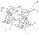
Fig. 1 is a schematic structural view of a landing gear for automobile maintenance according to the present invention.
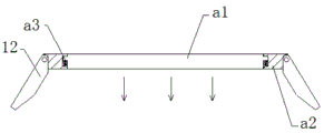
FIG. 2 is a schematic side view of a portion of a landing gear half-section of the present invention.
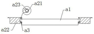
FIG. 3 is a side view of a half-section of the support panel of the present invention.
FIG. 4 is a schematic structural diagram of a side view of a half-section of the panel according to the present invention.
FIG. 5 is a side view of a semi-sectional structure of the lower slide plate of the present invention.
FIG. 6 is a side view of a half-section of the upper boom of the present invention.
Fig. 7 is a side view of the plate with a half-section structure.
FIG. 8 is a schematic side view of a half-section of the lumen of the present invention.
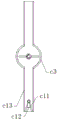
FIG. 9 is a side view of a half-section of a guide cavity according to the present invention.
In the figure: the lifting mechanism comprises a lifting mechanism-1, a bottom plate-2, a hydraulic rod-3, a connecting rod-4, a supporting panel-11, a guide plate-12, a telescopic frame-13, a lower sliding plate-a 1, a plate surface-a 2, an elastic strip-a 3, a protective surface-a 21, an outer plate surface-a 22, an elastic ring-a 23, an upper extension rod-a 11, a boosting ring-a 12, a plate-a 13, a contact surface-b 1, a grabbing bar-b 2, a stabilizing sheet-b 3, a rod body-b 4, a guide cavity-c 1, a connecting plate-c 2, a middle connecting cavity-c 3, a rebound strip-c 31, a rotating frame-c 32, a central block-c 33, an external frame-c 34, an internal swinging plate-c 11, a reset sheet-c 12 and a frame-c 13.
Detailed Description
The technical solutions in the embodiments of the present invention will be clearly and completely described below with reference to the drawings in the embodiments of the present invention, and it is obvious that the described embodiments are only a part of the embodiments of the present invention, and not all of the embodiments. All other embodiments, which can be derived by a person skilled in the art from the embodiments given herein without making any creative effort, shall fall within the protection scope of the present invention.
Example 1
As shown in fig. 1-6:
the invention provides a lifting device for automobile maintenance, which structurally comprises lifting mechanisms 1, a driving bottom plate 2, a hydraulic rod 3 and a connecting rod 4, wherein the hydraulic rod 3 is arranged between the upper end of the driving bottom plate 2 and the lifting mechanisms 1, the connecting rod 4 is fixed between the inner sides of the two lifting mechanisms 1, and the lifting mechanisms 1 are movably clamped with the upper end of the driving bottom plate 2; the lifting mechanism 1 comprises a supporting panel 11, a guiding plate 12 and an expansion bracket 13, wherein the supporting panel 11 is movably clamped with the upper end of a bottoming plate 2, the left end of the expansion bracket 13 is connected with the upper end of a hydraulic rod 3, the inner side of the expansion bracket 13 is connected with a connecting rod 4, the supporting panel 11 is movably clamped with the upper end of the expansion bracket 13, and the guiding plate 12 is hinged with the side of the supporting panel 11.
The support panel 11 includes a lower sliding plate a1, a plate surface a2, and an elastic strip a3, the plate surface a2 is movably engaged with the upper end of the telescopic frame 13, the edge side of the plate surface a2 is hinged to the guide plate 12, the lower sliding plate a1 is movably engaged with the inner side of the plate surface a2, the elastic strip a3 is installed between the inner wall of the plate surface a2 and the lower sliding plate a1, and the lower sliding plate a1 can slide downwards along the plate surface a2 by the pressure of the automobile wheel on the lower sliding plate a1, so that the concave surface generated on the plate surface a2 can limit the wheel of the automobile.
The plate surface a2 comprises a protection surface a21, an outer plate surface a22 and an elastic ring a23, the inside of the outer plate surface a22 is movably clamped with a lower sliding plate a1, the inner wall of the outer plate surface a22 is connected with an elastic strip a3, the protection surface a21 is embedded in the inner side of the outer plate surface a22, the elastic ring a23 is installed between the protection surface a21 and the outer plate surface a22, the protection surface a21 is made of a nitrile rubber material with high density, the wheel can be protected by the object protection surface a21, and accordingly the situation that the wheel is pricked by the outer plate surface a22 can be avoided.
The lower sliding plate a1 comprises an upper extension rod a11, a boosting ring a12 and a plate a13, the plate a13 is movably clamped with the inner side of the plate a2, the edge side of the plate a13 is connected with an elastic strip a3, the upper extension rod a11 is in clearance fit with the plate a13, the boosting ring a12 is installed between the bottom of the upper extension rod a11 and the bottom of the inner wall of the plate a13, six upper extension rods a11 are arranged and uniformly distributed in parallel in the plate a13, and the boosting ring a12 generates upward continuous pushing force on the upper extension rod a11, so that the upper end of the upper extension rod a11 can extend into a groove on the surface of a wheel, and the wheels of the automobile can be grabbed, and the automobile cannot move on an object.
The upper extension rod a11 comprises a contact surface b1, a grabbing bar b2, a stabilizing sheet b3 and a rod body b4, wherein the rod body b4 is in clearance fit with the inside of the plate a13, the bottom of the rod body b4 is connected with a boosting ring a12, the grabbing bar b2 is installed at the upper surface of the contact surface b1, the stabilizing sheet b3 is embedded into the inside of the rod body b4 and close to the upper end, the upper surface of the rod body b4 is attached to the bottom of the contact surface b1, the grabbing bar b2 and the contact surface b1 are made of soft natural rubber materials, and the grabbing force of the rod body b4 on wheels can be enhanced through the contact surface b 1.
The detailed use method and action of the embodiment are as follows:
in the invention, an automobile is driven onto a support panel 11 on a lifting mechanism 1, then an upward thrust is generated on a telescopic frame 13 through a hydraulic rod 3, the telescopic frame 13 can push the support panel 11 to ascend, so that the support panel 11 can lift the automobile, then a lower sliding plate a1 can slide downwards along a plate surface a2 through the pressure generated by the wheels of the automobile on a lower sliding plate a1, the position of the wheel can be limited, the wheel can be protected under the support of an elastic ring a23 through a protection surface a21, so that the condition that the wheel is punctured by the plate surface a2 can be avoided, the continuous thrust generated on an upper extension rod a11 through a boosting ring a12, the upper extension rod a11 can slide upwards along the plate a13, so that the upper extension rod a11 can extend into the groove on the surface of the wheel, the grip on the wheel can be enhanced, the grip of the upper extension rod a11 on the wheel can be further enhanced through a contact surface b1 and a grip strip b2, therefore, the automobile can keep still on the support panel 11, and the situation that the automobile moves on the support panel 11 due to the fact that the hand brake is forgotten to be pulled when the automobile runs onto the support panel 11 is effectively avoided.
Example 2
As shown in fig. 7-9:
the plate a13 comprises a guide cavity c1, a connecting plate c2 and a middle connecting cavity c3, the interior of the connecting plate c2 is in clearance fit with the upper extending rod a11, the bottom of the inner wall of the connecting plate c2 is connected with a boosting ring a12, the guide cavity c1 penetrates through the interior of the connecting plate c2, the middle connecting cavity c3 is embedded and fixed in the middle of the guide cavity c1, the guide cavity c1 is of a hollow structure, sand swept on the upper surface of the connecting plate c2 can be guided into the guide cavity c1, and then the sand can be guided downwards through the guide cavity c 1.
The middle joint cavity c3 comprises a rebound bar c31, a rotating frame c32, a center block c33 and an external frame c34, the external frame c34 is embedded and fixed in the middle of the guide cavity c1, the rebound bar c31 is installed between the inner side of the rotating frame c32 and the outer surface of the center block c33, the inner part of the rotating frame c32 is movably clamped with the outer surface of the center block c33, the center block c33 is embedded and fixed in the inner position of the external frame c34, the rotating frame c32 can rotate downwards along the center block c33 through thrust generated by sand on the rotating frame c32, and then the rebound bar c31 can push the rotating frame c32 to quickly reset, so that air flow can be generated to blow off the sand attached to the internal wall of the external frame c34 and the object.
The guide cavity c1 comprises an inner swinging plate c11, a reset plate c12 and a frame c13, the frame c13 penetrates through the inner position of the connecting plate c2, the middle of the frame c13 is fixedly connected with the middle connecting cavity c3 in an embedded mode, the inner swinging plate c11 is connected with the inner hinge of the frame c13, the reset plate c12 is installed between the inner sides of the two inner swinging plates c11, the two inner swinging plates c11 are arranged and are uniformly distributed below the inner wall of the frame c13 in a symmetrical mode, and the inner swinging plate c11 can swing towards the middle part through thrust generated by sand and soil led out downwards through the frame c13 to the inner swinging plate c11, so that the sand and soil can be discharged outwards through the space between the inner wall of the frame c13 and the inner swinging plate c 11.
The detailed use method and action of the embodiment are as follows:
in the invention, as the sand adheres to the wheels during the driving of the automobile, if the sand adheres to the wheels, the wheels fall on the lower sliding plate a1 of the support panel 11, but the lower sliding plate a1 slides downwards under pressure, so that when the sand on the upper surface of the lower sliding plate a1 is swept, part of the sand is clamped between the pressure-induced downward sliding of the lower sliding plate a1 and the inner side of the elastic strip a3, and is difficult to be cleaned up quickly, the sand swept on the upper surface of the lower sliding plate a1 can be guided into the lower sliding plate a by the guide cavity c1 and then guided out downwards by the guide cavity c1, and the rotating frame 737c 3 can rotate downwards along the central block c33 by the thrust of a large amount of sand on the rotating frame c32, and the rotating frame c32 can be pushed by the rebound strip c31 to reset quickly, so that air flow can be generated to blow off the sand adhering to the inner walls of the guide cavities 34 and c1 and the middle receiving cavity c3, the thrust generated by the inward swinging plate c11 is discharged downwards through a large amount of sandy soil, the inward swinging plate c11 can swing towards the middle, so that the sandy soil can be discharged outwards between the inner wall of the frame body c13 and the inward swinging plate c11, the inward swinging plate c11 which is pushed to lose the sandy soil can be pushed to swing outwards through the reset sheet c12 to reset, the inward swinging plate c11 can block dust entering the guide cavity c1 from the outside, and the situation that when the sandy soil on the upper surface of the lower sliding plate a1 is swept away, part of sandy soil is clamped between the pressure-borne downward sliding of the lower sliding plate a1 and the inner side of the elastic strip a3, and the situation that the fast cleaning is difficult can be realized is effectively avoided.
The technical solutions of the present invention or similar technical solutions designed by those skilled in the art based on the teachings of the technical solutions of the present invention are all within the scope of the present invention to achieve the above technical effects.
Claims (8)
1. The utility model provides a landing gear that auto repair used, its structure includes landing gear (1), beat bottom plate (2), hydraulic stem (3), connecting rod (4), install between the upper end of beating bottom plate (2) and landing gear (1) hydraulic stem (3), connecting rod (4) are fixed in between the inboard of two landing gear (1), its characterized in that: the lifting mechanism (1) is movably clamped with the upper end of the bottom plate (2);
the utility model discloses a hydraulic lifting mechanism, including landing gear (1) including supporting panel (11), guide board (12), expansion bracket (13), supporting panel (11) and the upper end activity block of backing plate (2), the left end of expansion bracket (13) is connected with the upper end of hydraulic stem (3), the inboard of expansion bracket (13) is connected with connecting rod (4), the upper end activity block of supporting panel (11) and expansion bracket (13), the avris hinged joint of guide board (12) and supporting panel (11).
2. A landing gear for servicing of automobiles, according to claim 1, wherein: support panel (11) are including slide down (a 1), face (a 2), elasticity strip (a 3), the upper end activity block of face (a 2) and expansion bracket (13), the avris and the guide board (12) hinged joint of face (a 2), the inboard activity block of slide down (a 1) and face (a 2), install in the inner wall of face (a 2) and down between slide (a 1) elasticity strip (a 3).
3. A landing gear for servicing of automobiles, according to claim 2, wherein: the face (a 2) includes protecting surface (a 21), planking face (a 22), elasticity ring (a 23), the inside and the gliding plate (a 1) activity block of outer face (a 22), the inner wall and the elasticity strip (a 3) of outer face (a 22) are connected, protecting surface (a 21) is embedded and is fixed in the inboard position of outer face (a 22), elasticity ring (a 23) is installed between protecting surface (a 21) and outer face (a 22).
4. A landing gear for servicing of automobiles, according to claim 2, wherein: the lower sliding plate (a 1) comprises an upper extension rod (a 11), a boosting ring (a 12) and a plate (a 13), wherein the plate (a 13) is movably clamped with the inner side of a plate surface (a 2), the edge side of the plate (a 13) is connected with an elastic strip (a 3), the upper extension rod (a 11) is in clearance fit with the plate (a 13), and the boosting ring (a 12) is arranged between the bottom of the upper extension rod (a 11) and the bottom of the inner wall of the plate (a 13).
5. A landing gear for servicing of automobiles, according to claim 3, wherein: go up stretch out pole (a 11) and include contact surface (b 1), increase and grab strip (b 2), stabilizer blade (b 3), body of rod (b 4), the inside clearance fit of body of rod (b 4) and plate (a 13), the bottom of body of rod (b 4) is connected with boosting ring (a 12), increase and grab strip (b 2) and install the upper surface position in contact surface (b 1), stabilizer blade (b 3) imbeds in the inside of body of rod (b 4) and leans on upper end position, the upper surface of body of rod (b 4) is laminated with the bottom of contact surface (b 1).
6. A landing gear for servicing of automobiles, according to claim 3, wherein: the plate (a 13) comprises a guide cavity (c 1), a connecting plate (c 2) and a middle joint cavity (c 3), the inside of the connecting plate (c 2) is in clearance fit with an upper extending rod (a 11), the bottom of the inner wall of the connecting plate (c 2) is connected with a boosting ring (a 12), the guide cavity (c 1) penetrates through the inner position of the connecting plate (c 2), and the middle joint cavity (c 3) is embedded in the middle position of the guide cavity (c 1).
7. A landing gear for servicing of vehicles according to claim 6, wherein: the middle joint cavity (c 3) comprises a rebound bar (c 31), a rotating frame (c 32), a center block (c 33) and an external frame (c 34), the external frame (c 34) is embedded in the middle of the guide cavity (c 1), the rebound bar (c 31) is installed between the inner side of the rotating frame (c 32) and the outer surface of the center block (c 33), the inner part of the rotating frame (c 32) is movably clamped with the outer surface of the center block (c 33), and the center block (c 33) is embedded in the inner position of the external frame (c 34).
8. A landing gear for servicing of automobiles, according to claim 7, wherein: the guide cavity (c 1) comprises an inner swinging plate (c 11), a reset piece (c 12) and a frame body (c 13), the frame body (c 13) penetrates through the inner position of the connecting plate (c 2), the middle of the frame body (c 13) is fixedly connected with the middle connecting cavity (c 3) in an embedded mode, the inner swinging plate (c 11) is connected with the inner hinge of the frame body (c 13), and the reset piece (c 12) is installed between the inner sides of the two inner swinging plates (c 11).
Priority Applications (1)
| Application Number | Priority Date | Filing Date | Title |
|---|---|---|---|
| CN202111128043.4A CN113955669B (en) | 2021-09-26 | 2021-09-26 | Landing gear for automobile maintenance |
Applications Claiming Priority (1)
| Application Number | Priority Date | Filing Date | Title |
|---|---|---|---|
| CN202111128043.4A CN113955669B (en) | 2021-09-26 | 2021-09-26 | Landing gear for automobile maintenance |
Publications (2)
| Publication Number | Publication Date |
|---|---|
| CN113955669A true CN113955669A (en) | 2022-01-21 |
| CN113955669B CN113955669B (en) | 2023-04-07 |
Family
ID=79462224
Family Applications (1)
| Application Number | Title | Priority Date | Filing Date |
|---|---|---|---|
| CN202111128043.4A Active CN113955669B (en) | 2021-09-26 | 2021-09-26 | Landing gear for automobile maintenance |
Country Status (1)
| Country | Link |
|---|---|
| CN (1) | CN113955669B (en) |
Cited By (1)
| Publication number | Priority date | Publication date | Assignee | Title |
|---|---|---|---|---|
| CN114852918A (en) * | 2022-04-07 | 2022-08-05 | 董风 | Washable safe lifting device for automobile maintenance |
Citations (4)
| Publication number | Priority date | Publication date | Assignee | Title |
|---|---|---|---|---|
| US20160039646A1 (en) * | 2014-08-07 | 2016-02-11 | Ryan W. Knapp | Low Profile Drop Table |
| CN111807254A (en) * | 2020-07-06 | 2020-10-23 | 广东国智机械科技有限公司 | Automobile elevator for automobile repair |
| CN212246076U (en) * | 2020-05-20 | 2020-12-29 | 聂斐 | Landing gear for automobile maintenance |
| CN112903314A (en) * | 2021-02-23 | 2021-06-04 | 邹芳 | Automobile detection platform |
-
2021
- 2021-09-26 CN CN202111128043.4A patent/CN113955669B/en active Active
Patent Citations (4)
| Publication number | Priority date | Publication date | Assignee | Title |
|---|---|---|---|---|
| US20160039646A1 (en) * | 2014-08-07 | 2016-02-11 | Ryan W. Knapp | Low Profile Drop Table |
| CN212246076U (en) * | 2020-05-20 | 2020-12-29 | 聂斐 | Landing gear for automobile maintenance |
| CN111807254A (en) * | 2020-07-06 | 2020-10-23 | 广东国智机械科技有限公司 | Automobile elevator for automobile repair |
| CN112903314A (en) * | 2021-02-23 | 2021-06-04 | 邹芳 | Automobile detection platform |
Cited By (2)
| Publication number | Priority date | Publication date | Assignee | Title |
|---|---|---|---|---|
| CN114852918A (en) * | 2022-04-07 | 2022-08-05 | 董风 | Washable safe lifting device for automobile maintenance |
| CN114852918B (en) * | 2022-04-07 | 2023-06-16 | 董风 | Flushable safety lifting device for automobile maintenance |
Also Published As
| Publication number | Publication date |
|---|---|
| CN113955669B (en) | 2023-04-07 |
Similar Documents
| Publication | Publication Date | Title |
|---|---|---|
| CN113955669A (en) | Landing gear for automobile maintenance | |
| CN110640706A (en) | Portable hardware tool box | |
| CN208715241U (en) | A kind of chemical industry charging basket locomotive | |
| CN208102197U (en) | A kind of flexible wind deflector of battery truck | |
| CN211775945U (en) | Foot support for curtain wall decoration engineering | |
| CN113600372B (en) | A automatically regulated paint spraying machine for new energy automobile makes | |
| CN212375573U (en) | Clothes hanger with reinforcing sleeve | |
| CN210454594U (en) | Automatic over-and-under type car as a house roof | |
| CN113243813A (en) | High-altitude window wiping robot with falling protection function | |
| CN209034922U (en) | Mud scraper | |
| CN113129621A (en) | Movable anti-collision traffic signal lamp | |
| CN217259980U (en) | Emergency guarantee vehicle supporting device | |
| CN214029106U (en) | Long-endurance intelligent unmanned aerial vehicle capable of landing in buffering mode | |
| CN108528687B (en) | Adjustable intelligent landing gear of amphibious aircraft | |
| CN211369935U (en) | Novel anti-prying hinge for installing anti-theft door | |
| CN215334128U (en) | Double-cylinder support type automobile shock absorber cylinder | |
| CN215414402U (en) | Green building compressed air system energy-saving assessment testing device | |
| CN211721762U (en) | Ice cream machine with micro-gap switch device | |
| CN220747345U (en) | Aluminum veneer curtain wall with buffer function | |
| CN203496634U (en) | Abat vent handle plate | |
| CN214313041U (en) | Low-pressure alarm switch for automobile tire | |
| CN216101431U (en) | Automobile balancing pole convenient for replacing rubber sleeve | |
| CN210658174U (en) | Novel washing and sweeping vehicle suction nozzle | |
| CN217415585U (en) | Combined type pickup truck box cover plate aluminum profile | |
| CN220502357U (en) | Back wheel locking device |
Legal Events
| Date | Code | Title | Description |
|---|---|---|---|
| PB01 | Publication | ||
| PB01 | Publication | ||
| SE01 | Entry into force of request for substantive examination | ||
| SE01 | Entry into force of request for substantive examination | ||
| GR01 | Patent grant | ||
| GR01 | Patent grant |