CN113948267A - High-strength coil supporting platform applied to pulse discharge connection - Google Patents
High-strength coil supporting platform applied to pulse discharge connection Download PDFInfo
- Publication number
- CN113948267A CN113948267A CN202111411417.3A CN202111411417A CN113948267A CN 113948267 A CN113948267 A CN 113948267A CN 202111411417 A CN202111411417 A CN 202111411417A CN 113948267 A CN113948267 A CN 113948267A
- Authority
- CN
- China
- Prior art keywords
- pipe
- fixed
- air inlet
- supporting platform
- pulse discharge
- Prior art date
- Legal status (The legal status is an assumption and is not a legal conclusion. Google has not performed a legal analysis and makes no representation as to the accuracy of the status listed.)
- Granted
Links
Images


Classifications
-
- H—ELECTRICITY
- H01—ELECTRIC ELEMENTS
- H01F—MAGNETS; INDUCTANCES; TRANSFORMERS; SELECTION OF MATERIALS FOR THEIR MAGNETIC PROPERTIES
- H01F5/00—Coils
-
- H—ELECTRICITY
- H05—ELECTRIC TECHNIQUES NOT OTHERWISE PROVIDED FOR
- H05K—PRINTED CIRCUITS; CASINGS OR CONSTRUCTIONAL DETAILS OF ELECTRIC APPARATUS; MANUFACTURE OF ASSEMBLAGES OF ELECTRICAL COMPONENTS
- H05K5/00—Casings, cabinets or drawers for electric apparatus
- H05K5/02—Details
- H05K5/0217—Mechanical details of casings
- H05K5/0234—Feet; Stands; Pedestals, e.g. wheels for moving casing on floor
Abstract
The invention discloses a high-strength coil supporting platform applied to pulse discharge connection, which comprises an insulating plane, wherein a pulse current generator and a coil are arranged at the upper end of the insulating plane, a lead is connected between the pulse current generator and the coil, a supporting table is arranged at the lower end of the insulating plane, an electric cylinder and an air cylinder are arranged at the lower end of the supporting table, a lubricating device is connected outside the air cylinder at the lower end of the supporting table, the lubricating device comprises a storage mechanism and a coating mechanism, lubricating oil in the storage mechanism is discharged into the coating mechanism by the movement of the air cylinder to coat the air cylinder, the invention aims to provide the high-strength coil supporting platform applied to the pulse discharge connection, the strength of the insulating plane can be improved, the insulating requirement can be met, the high-strength coil supporting platform is suitable for large-scale pulse discharge, and the supporting table can be well supported and height can be adjusted, the self-lubricating oil is stable, can achieve the purpose of self-lubricating, and does not need manual addition.
Description
Technical Field
The invention relates to the technical field of pulse discharge, in particular to a high-strength coil supporting platform applied to pulse discharge connection.
Background
At present, a known work coil support platform is composed of a positive terminal, a negative terminal, a support frame, a support plane, support legs and other components. The comprehensive consideration of insulating property, mobility and the like, the support plane can not be made of high-strength materials such as high-strength steel and the like, and needs to be made of insulating materials such as epoxy resin boards and wood materials, so that the mechanical strength of the working platform is poor, the reliable support of the light-weight and small-size working coil can be met, the further improvement of the Lorentz force of the working coil is restricted, the Lorentz force is one of important direct factors influencing the processing effect, and the application range and the processing effect of pulse discharge connection are further limited. On the other hand, the high-strength working platform adopts a fixed mechanical structure, and the working height cannot be changed along with the change of the workpiece and the use scene, so that the use of different coils and processed workpieces is difficult to meet.
Disclosure of Invention
The present invention is directed to a high-strength coil supporting platform for pulse discharge connection, so as to solve the above-mentioned problems in the prior art.
In order to achieve the purpose, the invention provides the following technical scheme: the utility model provides a be applied to pulse discharge connection's high strength coil supporting platform, includes insulating plane, insulating planar upper end is provided with pulse current generator and coil, be connected with the wire between pulse current generator and the coil, insulating planar lower extreme is provided with a supporting bench, electronic jar and cylinder are installed to a supporting bench's lower extreme, the external connection of a supporting bench's lower extreme cylinder has lubricating arrangement, lubricating arrangement is including storing the mechanism and paining the mechanism, the cylinder motion will be stored the lubricating oil in the mechanism and arrange to paint the mechanism inside and paint the cylinder.
Preferably, the cylinder includes a cylinder sleeve and a piston rod, the piston rod is connected to the inner upper end of the cylinder sleeve in a sealing and sliding manner, the upper end of the piston rod is fixed to the center of the lower end of the support platform, and the cylinder sleeve is mounted on the upper end of the ground through a bolt.
Preferably, the storage mechanism comprises an oil storage box arranged at the lower end of the support table, the lower end of the oil storage box is communicated and connected with an air inlet main pipe, the lower end of the air inlet main pipe is communicated and connected with the bottom of the cylinder sleeve, and one end of the oil storage box is communicated and connected with a first air inlet branch pipe and a second air inlet branch pipe.
Preferably, air intake main includes first hose portion and first hard tube portion, first hard tube portion fixes the upper end at first hose portion, just first hard tube portion is connected with the lower extreme of oil storage box, the surface mounting of first hard tube portion has first valve, first hose portion is connected with the bottom of cylinder liner.
Preferably, a second valve is mounted on the surface of the first air inlet branch pipe, a third valve is mounted on the surface of the second air inlet branch pipe, and the second air inlet branch pipe is located above the first air inlet branch pipe.
Preferably, the upper end of oil storage box can be dismantled and be connected with the connecting plate, the lower extreme at a supporting bench is fixed to the connecting plate, the inside of oil storage box slides and is provided with the piston board, the size of piston board and the internal dimension looks adaptation of oil storage box, the upper end fixedly connected with expanding spring of piston board, the lower extreme at the connecting plate is fixed to expanding spring's upper end.
Preferably, the smearing mechanism comprises a fixed shell fixed at the upper end of the cylinder sleeve, the fixed shell is located at the joint of the cylinder sleeve and the piston rod, an anti-seepage cover is integrally connected to the upper end of the fixed shell, the anti-seepage cover is a hollow pipe-mounted structure with a large upper part and a small lower part, and the diameter of the joint of the anti-seepage cover and the fixed shell is the same as that of the fixed shell.
Preferably, the inner surface of the fixed shell is provided with a smearing ring, the inner surface of the smearing ring is attached to the surface of the piston rod, the smearing ring is in sliding connection with the piston rod, and the smearing ring is made of sponge materials.
Preferably, the one end intercommunication of prevention of seepage cover is provided with into oil pipe, it includes second hose portion and the hard pipe portion of second to advance oil pipe, second hose portion is connected with the prevention of seepage cover, the upper end intercommunication of the hard pipe portion of second is provided with fixed pipe, the fourth valve is installed to the one end of the hard pipe portion of second, fixed pipe fixed mounting is on the surface of oil storage box, fixed pipe is located between first air inlet branch pipe and the second air inlet branch pipe, one side that the surface of fixed pipe is close to the hard pipe portion of second is provided with the check valve, expanding spring piston plate is located the top of fixed pipe when natural state.
Preferably, a through hole is formed in the center of the surface of the insulation plane, a buckle is installed inside the through hole, the wire is fixed to the upper end of the insulation plane through the buckle, the coil is electrically connected with the pulse current generator through the wire, the range of the electric cylinder is 70cm-130cm, the thickness of the insulation plane is 3cm-5cm, the supporting table is made of high-strength steel, and the length and the width of the supporting table are both 60 cm.
Compared with the prior art, the invention has the beneficial effects that:
1. can play support and fixed effect to insulating plane through the brace table, improve insulating planar intensity, and can satisfy the insulation requirement, be suitable for large-scale pulse discharge and use, increase application range.
2. When the height of the insulating plane needs to be adjusted, the electric cylinder is started to drive the supporting table to move up and down, so that the insulating plane can be adjusted, the working height can be changed along with the change of the workpiece and the use scene, and the use of different coils and processed workpieces can be met.
3. When the electric cylinder moves upwards, the fourth valve and the third valve are closed, the first valve and the second valve are opened, the electric cylinder drives the support table to move upwards, the support table can drive the piston rod to move upwards in the cylinder sleeve, the piston rod can move upwards to suck air from the inside of the cylinder sleeve, external air can enter the inside of the cylinder sleeve from the first air inlet branch pipe and the air inlet main pipe, the electric cylinder is closed after the height adjustment of the support table is completed, the first valve and the second valve are closed, pressure can be generated in the inside of the cylinder sleeve, the piston rod can be jacked up through the air in the cylinder sleeve, the piston rod is further supported at the lower end of the support table, when the electric cylinder moves downwards, the first valve and the second valve are opened, the air in the cylinder sleeve can be discharged through the air inlet main pipe and the first air inlet branch pipe, the purpose of downward adjustment of the support table is achieved, and the pressure of the electric cylinder can be shared, protect electronic jar, and can play good supporting role to the brace table through the cooperation of cylinder, electronic jar, it is more firm.
4. When lubricating oil needs to be added to the surface of the piston rod, the first valve, the third valve and the fourth valve are opened, the second valve is closed, the electric cylinder drives the supporting table to move upwards, the piston rod can be driven to move upwards in the cylinder sleeve through the supporting table, air can be sucked into the cylinder sleeve through the upward movement of the piston rod, the cylinder sleeve sucks the oil storage box through the air inlet main pipe, the piston plate can slide downwards in the oil storage box, external air enters the oil storage box from the second air inlet branch pipe, when the piston plate slides to the lower part of the fixed pipe, the lubricating oil in the oil storage box enters the anti-seepage cover and the inner surface of the fixed shell from the fixed pipe and the oil inlet pipe, the lubricating oil can be absorbed by the smearing ring in the fixed shell and coated on the surface of the sliding piston rod, the anti-seepage cover can play a role in containing the lubricating oil, and excessive lubricating oil can conveniently overflow, the lubricating oil is convenient to add, the purpose of self-lubricating can be achieved, manual addition is not needed, and the service life of the air cylinder can be prolonged.
Drawings
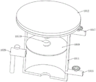
FIG. 1 is a schematic diagram of an overall structure of a high-strength coil support platform for pulse discharge connection according to the present invention;
FIG. 2 is a schematic diagram of an overall structure of a high-strength coil support platform for pulse discharge connection according to the present invention;
FIG. 3 is a schematic diagram of a partial structure of a high-strength coil support platform for pulse discharge connection according to the present invention;
FIG. 4 is a schematic structural diagram of a cylinder and a lubricating device of a high-strength coil supporting platform applied to a pulse discharge connection according to the present invention;
FIG. 5 is a schematic structural diagram of a lubricating device for a high-strength coil supporting platform for pulse discharge connection according to the present invention;
FIG. 6 is a schematic diagram of a partial structure of a storage mechanism of a high-strength coil support platform for pulse discharge connection according to the present invention;
FIG. 7 is a schematic diagram of a partial explosion structure of a storage mechanism of a high-strength coil support platform for a pulsed discharge connection according to the present invention;
FIG. 8 is a schematic view of a cutaway structure of an oil storage box of a high-strength coil support platform applied to pulse discharge connection according to the present invention;
FIG. 9 is a schematic structural diagram of a coating mechanism of a high-strength coil support platform for pulse discharge connection according to the present invention;
fig. 10 is a sectional structure diagram of a fixed shell, an anti-seepage cover and a smearing ring of a high-strength coil supporting platform applied to pulse discharge connection.
In the figure: 1. an insulating plane; 2. a pulse current generator; 3. a coil; 4. a wire; 5. buckling; 6. a support table; 7. an electric cylinder; 8. a cylinder; 81. a cylinder liner; 82. a piston rod; 9. a ground surface; 10. a lubricating device; 101. a storage mechanism; 1011. an oil storage box; 1012. a connecting plate; 1013. an intake manifold; 1014. a first valve; 1015. a first intake branch pipe; 1016. a second valve; 1017. a second intake branch pipe; 1018. a third valve; 1019. a piston plate; 10110. a tension spring; 102. a smearing mechanism; 1021. fixing the housing; 1022. an impermeable cover; 1023. an oil inlet pipe; 1024. a fourth valve; 1025. a fixed tube; 1026. a one-way valve; 1027. and (6) coating a ring.
Detailed Description
The technical solutions in the embodiments of the present invention will be clearly and completely described below with reference to the drawings in the embodiments of the present invention, and it is obvious that the described embodiments are only a part of the embodiments of the present invention, and not all of the embodiments. All other embodiments, which can be derived by a person skilled in the art from the embodiments given herein without making any creative effort, shall fall within the protection scope of the present invention.
Referring to fig. 1 to 10, the present invention provides a high strength coil supporting platform applied to pulse discharge connection, including an insulation plane 1, an upper end of the insulation plane 1 is provided with a pulse current generator 2 and a coil 3, a wire 4 is connected between the pulse current generator 2 and the coil 3, a lower end of the insulation plane 1 is provided with a supporting table 6, a lower end of the supporting table 6 is provided with an electric cylinder 7 and an air cylinder 8, an outer portion of the air cylinder 8 at the lower end of the supporting table 6 is connected with a lubricating device 10, the lubricating device 10 includes a storage mechanism 101 and a coating mechanism 102, and the air cylinder 8 moves to discharge lubricating oil in the storage mechanism 101 into the coating mechanism 102 to coat the air cylinder 8.
In this embodiment, the air cylinder 8 includes a cylinder sleeve 81 and a piston rod 82, the piston rod 82 is connected to the inner upper end of the cylinder sleeve 81 in a sealing and sliding manner, the upper end of the piston rod 82 is fixed to the center of the lower end of the support platform 6, and the cylinder sleeve 81 is installed on the upper end of the ground 9 through a bolt.
Specifically, the piston rod 82 slides upward inside the cylinder sleeve 81 to suck external air into the cylinder sleeve 81, thereby supporting and stabilizing the support table 6.
In this embodiment, the storage mechanism 101 includes the oil storage box 1011 installed at the lower end of the support platform 6, the lower end of the oil storage box 1011 is connected with the air intake manifold 1013, the lower end of the air intake manifold 1013 is connected with the bottom of the cylinder sleeve 81, and the one end of the oil storage box 1011 is connected with the first air intake branch pipe 1015 and the second air intake branch pipe 1017.
Specifically, when the support base 6 needs to be supported, the outside air can be sucked into the inside of the oil storage box 1011 through the first intake branch pipe 1015 and then into the cylinder sleeve 81 through the intake manifold 1013, and when the cylinder 8 needs to be lubricated, the outside air is sucked into the inside of the oil storage box 1011 through the second intake branch pipe 1017, so that the oil level inside the oil storage box 1011 is changed.
In this embodiment, the intake manifold 1013 includes a first hose portion and a first hard tube portion, the first hard tube portion is fixed to the upper end of the first hose portion, the first hard tube portion is connected to the lower end of the oil storage box 1011, a first valve 1014 is installed on the surface of the first hard tube portion, and the first hose portion is connected to the bottom of the cylinder sleeve 81.
Specifically, the first valve 1014 is closed to prevent gas from being discharged from the cylinder liner 81, and the first hose portion is compressed and extended according to the height of the support table 6, thereby facilitating use.
In this embodiment, a second valve 1016 is mounted on a surface of the first branch intake pipe 1015, a third valve 1018 is mounted on a surface of the second branch intake pipe 1017, and the second branch intake pipe 1017 is located above the first branch intake pipe 1015.
Specifically, the air inlet and outlet of the first air inlet branch pipe 1015 can be controlled through the second valve 1016, and the air inlet and outlet of the second air inlet branch pipe 1017 can be controlled through the third valve 1018.
In this embodiment, the upper end of oil storage box 1011 can be dismantled and be connected with connecting plate 1012, and connecting plate 1012 fixes the lower extreme at a supporting bench 6, and the inside of oil storage box 1011 slides and is provided with piston plate 1019, and the inside size looks adaptation of piston plate 1019 and oil storage box 1011, the upper end fixedly connected with expanding spring 10110 of piston plate 1019, and the lower extreme at connecting plate 1012 is fixed to expanding spring 10110's upper end.
Specifically, can install oil storage box 1011 through connecting plate 1012 at the lower extreme of propping up a supporting bench 6, be convenient for dismantle oil storage box 1011, can control the emission of the inside lubricating oil of oil storage box 1011 through changing piston plate 1019's position, can reset piston plate 1019 through expanding spring 10110.
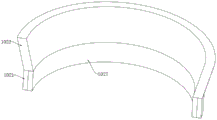
In this embodiment, the smearing mechanism 102 includes a fixed casing 1021 fixed at the upper end of the cylinder sleeve 81, the fixed casing 1021 is located at the joint of the cylinder sleeve 81 and the piston rod 82, an anti-seepage cover 1022 is integrally connected to the upper end of the fixed casing 1021, the anti-seepage cover 1022 is a hollow pipe-mounted structure with a large top and a small bottom, and the diameter of the joint of the anti-seepage cover 1022 and the fixed casing 1021 is the same as the diameter of the fixed casing 1021.
Specifically, the anti-seepage cover 1022 can be used for containing lubricating oil, so that excessive lubricating oil can overflow conveniently.
In this embodiment, the inner surface of the fixed housing 1021 is provided with the smearing ring 1027, the inner surface of the smearing ring 1027 is attached to the surface of the piston rod 82, the smearing ring 1027 is in sliding connection with the piston rod 82, and the smearing ring 1027 is made of a sponge material.
Specifically, the coating ring 1027 of the sponge material inside the fixed housing 1021 can absorb the lubricant and coat the surface of the sliding piston rod 82.
In this embodiment, the one end intercommunication of prevention of seepage cover 1022 is provided with into oil pipe 1023, advance oil pipe 1023 and include second hose portion and the hard pipe portion of second, the second hose portion is connected with prevention of seepage cover 1022, the upper end intercommunication of the hard pipe portion of second is provided with fixed pipe 1025, fourth valve 1024 is installed to the one end of the hard pipe portion of second, fixed pipe 1025 fixed mounting is on the surface of oil storage box 1011, fixed pipe 1025 is located between first air inlet branch pipe 1015 and the second air inlet branch pipe 1017, one side that the surface of fixed pipe 1025 is close to the hard pipe portion of second is provided with check valve 1026, expanding spring 10110 piston board 1019 is located the top of fixed pipe 1025 when natural state.
Specifically, the second hose portion can be compressed and extended according to the height of the support table 6, the oil inlet amount of the oil inlet pipe 1023 can be controlled by the fourth valve 1024, excessive addition of lubricating oil is avoided, and the return flow of the lubricating oil from the oil inlet pipe 1023 is prevented by the check valve 1026.
In this embodiment, a through hole is provided in the center of the surface of the insulating plane 1, a buckle 5 is installed inside the through hole, a wire 4 is fixed to the upper end of the insulating plane 1 through the buckle 5, the coil 3 is electrically connected to the pulse current generator 2 through the wire 4, the range of the electric cylinder 7 is 70cm to 130cm, the thickness of the insulating plane 1 is 3cm to 5cm, the supporting table 6 is made of high-strength steel, and the length and the width of the supporting table 6 are both 60 cm.
Specifically, the supporting platform 6 can support and fix the insulating plane 1, the insulating plane 1 can insulate the pulse current generator 2 and the coil 3, and the height of the supporting platform 6 can be adjusted through the electric cylinder 7.
The working principle is as follows: when the device is used, the lead 4 is fixed at the upper end of the insulating plane 1 through the buckle 5, two ends of the lead 4 are connected with the pulse current generator 2 and the coil 3 to form a closed loop, after the pulse current generator 2 generates pulse heavy current, the pulse heavy current is transmitted into the coil 3 through the four leads 4, electromagnetic conversion occurs in the coil and the surrounding space thereof, the generated electromagnetic force is used for realizing pulse discharge connection, when the height of the insulating plane 1 needs to be adjusted, the electric cylinder 7 is started to drive the support table 6 to move up and down, the insulating plane 1 can be adjusted, when the electric cylinder 7 moves up, the fourth valve 1024 and the third valve 1018 are closed, the first valve 1014 and the second valve 1016 are opened, the electric cylinder 7 drives the support table 6 to move up, the piston rod 82 can be driven to move up in the cylinder sleeve 81 through the support table 6, the piston rod 82 can move up to pump the interior of the cylinder sleeve 81, the external air can enter the cylinder sleeve 81 from the first air inlet branch pipe 1015 and the air inlet main pipe 1013, the electric cylinder 7 is closed after the height adjustment of the support table 6 is completed, the first valve 1014 and the second valve 1016 are closed, pressure can be generated in the cylinder sleeve 81, the piston rod 82 can be jacked up by the air in the cylinder sleeve 81, the piston rod 82 is supported at the lower end of the support table 6, when the electric cylinder 7 moves downwards, the first valve 1014 and the second valve 1016 are opened, the gas in the cylinder sleeve 81 can be discharged through the air inlet main pipe 1013 and the first air inlet branch pipe 1015, the purpose of downward adjustment of the support table 6 is achieved, when lubricating oil needs to be added on the surface of the piston rod 82, the first valve 1014, the third valve 1018 and the fourth valve 1024 are opened, the second valve 1016 is closed, the support table 6 is driven to move upwards by the electric cylinder 7, the piston rod 82 can be driven to move upwards in the cylinder sleeve 81 by the support table 6, the cylinder sleeve 81 can be sucked by moving the piston rod 82 upwards, the cylinder sleeve 81 can suck the oil storage box 1011 by the air inlet manifold 1013, the piston plate 1019 can slide downwards in the oil storage box 1011, and the outside air enters the oil storage box 1011 from the second air inlet branch pipe 1017, when the piston plate 1019 slides to the lower part of the fixed pipe 1025, the lubricating oil in the oil storage box 1011 enters the inner surfaces of the anti-seepage cover 1022 and the fixed shell 1021 from the fixed pipe 1025 and the oil inlet pipe 1023, the lubricating oil can be absorbed by the smearing ring 1027 in the fixed shell 1021 and coated on the surface of the sliding piston rod 82, the lubricating oil can be stored by the anti-seepage cover, the excessive lubricating oil can overflow conveniently, and the connecting plate 1012 can be detached and added when the lubricating oil needs to be added into the oil storage box 1011.
Although embodiments of the present invention have been shown and described, it will be appreciated by those skilled in the art that changes, modifications, substitutions and alterations can be made in these embodiments without departing from the principles and spirit of the invention, the scope of which is defined in the appended claims and their equivalents.
Claims (10)
1. The utility model provides a be applied to high strength coil supporting platform that pulse discharge connects, includes insulating plane (1), its characterized in that, the upper end of insulating plane (1) is provided with pulse current generator (2) and coil (3), be connected with wire (4) between pulse current generator (2) and coil (3), the lower extreme of insulating plane (1) is provided with brace table (6), electronic jar (7) and cylinder (8) are installed to the lower extreme of brace table (6), the external connection of lower extreme cylinder (8) of brace table (6) has lubricating arrangement (10), lubricating arrangement (10) are including storing mechanism (101) and smearing mechanism (102), cylinder (8) motion is arranged the lubricating oil in storing mechanism (101) and is smeared mechanism (102) inside smearing cylinder (8).
2. The high-strength coil supporting platform applied to the pulse discharge connection as claimed in claim 1, wherein the air cylinder (8) comprises a cylinder sleeve (81) and a piston rod (82), the piston rod (82) is connected to the inner upper end of the cylinder sleeve (81) in a sealing and sliding manner, the upper end of the piston rod (82) is fixed to the lower end of the supporting platform (6) at the center, and the cylinder sleeve (81) is mounted on the upper end of the ground (9) through a bolt.
3. The high-strength coil supporting platform applied to the pulse discharge connection as claimed in claim 2, wherein the storage mechanism (101) comprises an oil storage box (1011) installed at the lower end of the supporting platform (6), the lower end of the oil storage box (1011) is connected with an air inlet main pipe (1013) in a communicating manner, the lower end of the air inlet main pipe (1013) is connected with the bottom of the cylinder sleeve (81), and one end of the oil storage box (1011) is connected with a first air inlet branch pipe (1015) and a second air inlet branch pipe (1017) in a communicating manner.
4. The high-strength coil support platform applied to the pulse discharge connection as claimed in claim 3, wherein the air inlet manifold (1013) comprises a first hose part and a first hard pipe part, the first hard pipe part is fixed at the upper end of the first hose part, the first hard pipe part is connected with the lower end of the oil storage box (1011), a first valve (1014) is mounted on the surface of the first hard pipe part, and the first hose part is connected with the bottom of the cylinder sleeve (81).
5. The high-strength coil support platform applied to the pulse discharge connection of claim 3, wherein a second valve (1016) is installed on the surface of the first air inlet branch pipe (1015), a third valve (1018) is installed on the surface of the second air inlet branch pipe (1017), and the second air inlet branch pipe (1017) is located above the first air inlet branch pipe (1015).
6. The high-strength coil supporting platform applied to pulse discharge connection according to claim 3, wherein a connecting plate (1012) is detachably connected to the upper end of the oil storage box (1011), the connecting plate (1012) is fixed to the lower end of the supporting platform (6), a piston plate (1019) is slidably arranged inside the oil storage box (1011), the size of the piston plate (1019) is matched with the inner size of the oil storage box (1011), a telescopic spring (10110) is fixedly connected to the upper end of the piston plate (1019), and the upper end of the telescopic spring (10110) is fixed to the lower end of the connecting plate (1012).
7. The high-strength coil supporting platform applied to the pulse discharge connection as claimed in claim 6, wherein the smearing mechanism (102) comprises a fixed casing (1021) fixed at the upper end of the cylinder sleeve (81), the fixed casing (1021) is located at the joint of the cylinder sleeve (81) and the piston rod (82), an anti-seepage cover (1022) is integrally connected to the upper end of the fixed casing (1021), the anti-seepage cover (1022) is a hollow pipe-mounted structure with a large upper part and a small lower part, and the diameter of the joint of the anti-seepage cover (1022) and the fixed casing (1021) is the same as that of the fixed casing (1021).
8. The high-strength coil supporting platform applied to the pulse discharge connection as claimed in claim 7, wherein an inner surface of the fixed shell (1021) is provided with a smearing ring (1027), an inner surface of the smearing ring (1027) is attached to a surface of the piston rod (82), the smearing ring (1027) is in sliding connection with the piston rod (82), and the smearing ring (1027) is made of sponge material.
9. The high-strength coil supporting platform applied to the pulse discharge connection as claimed in claim 7, it is characterized in that one end of the anti-seepage cover (1022) is communicated with an oil inlet pipe (1023), the oil inlet pipe (1023) comprises a second soft pipe part and a second hard pipe part, the second soft pipe part is connected with the anti-seepage cover (1022), the upper end of the second hard pipe part is communicated with a fixed pipe (1025), one end of the second hard pipe part is provided with a fourth valve (1024), the fixed pipe (1025) is fixedly arranged on the surface of the oil storage box (1011), the fixed pipe (1025) is positioned between the first air inlet branch pipe (1015) and the second air inlet branch pipe (1017), one side of the surface of the fixed pipe (1025), which is close to the second hard pipe part, is provided with a one-way valve (1026), the telescopic spring (10110) is arranged in a natural state, and the piston plate (1019) is positioned above the fixed pipe (1025).
10. The high-strength coil supporting platform applied to pulse discharge connection as claimed in claim 1, wherein a through hole is formed in the center of the surface of the insulating plane (1), a buckle (5) is installed inside the through hole, the wire (4) is fixed at the upper end of the insulating plane (1) through the buckle (5), the coil (3) is electrically connected with the pulse current generator (2) through the wire (4), the range of the electric cylinder (7) is 70cm-130cm, the thickness of the insulating plane (1) is 3cm-5cm, the supporting table (6) is made of high-strength steel, and the length and width of the supporting table (6) are both 60 cm.
Priority Applications (1)
| Application Number | Priority Date | Filing Date | Title |
|---|---|---|---|
| CN202111411417.3A CN113948267B (en) | 2021-11-25 | 2021-11-25 | High-strength coil supporting platform applied to pulse discharge connection |
Applications Claiming Priority (1)
| Application Number | Priority Date | Filing Date | Title |
|---|---|---|---|
| CN202111411417.3A CN113948267B (en) | 2021-11-25 | 2021-11-25 | High-strength coil supporting platform applied to pulse discharge connection |
Publications (2)
| Publication Number | Publication Date |
|---|---|
| CN113948267A true CN113948267A (en) | 2022-01-18 |
| CN113948267B CN113948267B (en) | 2022-07-01 |
Family
ID=79338688
Family Applications (1)
| Application Number | Title | Priority Date | Filing Date |
|---|---|---|---|
| CN202111411417.3A Active CN113948267B (en) | 2021-11-25 | 2021-11-25 | High-strength coil supporting platform applied to pulse discharge connection |
Country Status (1)
| Country | Link |
|---|---|
| CN (1) | CN113948267B (en) |
Citations (13)
| Publication number | Priority date | Publication date | Assignee | Title |
|---|---|---|---|---|
| CA2366173A1 (en) * | 2001-07-27 | 2003-01-27 | Imn Co., Ltd. | Method for lubricating a rotational-part supporter |
| KR20120053877A (en) * | 2010-11-18 | 2012-05-29 | 금오공과대학교 산학협력단 | Cctv camera for defending electromagnetic pulse |
| CN102862929A (en) * | 2012-08-23 | 2013-01-09 | 北京摩诘创新科技有限公司 | Six-degree of freedom motion platform |
| CN204042387U (en) * | 2014-08-06 | 2014-12-24 | 安徽国风塑业股份有限公司 | The horizontal zip strip lubricating fitting of a kind of film line |
| CN106583977A (en) * | 2016-12-29 | 2017-04-26 | 重庆市送变电工程有限公司 | Modular electromagnetic pulse welding platform |
| CN207710640U (en) * | 2017-12-14 | 2018-08-10 | 东莞市盛菱精密机械有限公司 | A kind of hardware combined piece clamp system that can laterally finely tune |
| CN108890114A (en) * | 2018-07-20 | 2018-11-27 | 太原理工大学 | Impulse electric field and the metal-base composites of ultrasonic field auxiliary are sintered synchronized links method and device |
| CN110240084A (en) * | 2019-04-30 | 2019-09-17 | 北京理工大学 | A kind of energy-saving stabilized platform and system |
| CN210912986U (en) * | 2019-08-30 | 2020-07-03 | 安徽金德润滑科技有限公司 | Lubricating oil liquid filling machine for filling |
| CN211248709U (en) * | 2019-12-11 | 2020-08-14 | 成都韵弘科技有限公司 | Rotary platform of pulse hot-press welder |
| EP3715194A1 (en) * | 2017-11-22 | 2020-09-30 | NIO Nextev Limited | Drifting abutting connection device, battery replacing robot, and locking, unlocking and locking-unlocking methods |
| EP3747599A1 (en) * | 2019-06-06 | 2020-12-09 | Citic Dicastal Co., Ltd. | Flexible automatic deburring device |
| CN212643220U (en) * | 2020-07-24 | 2021-03-02 | 浙江星辰气动有限公司 | Small self-lubricating cylinder |
-
2021
- 2021-11-25 CN CN202111411417.3A patent/CN113948267B/en active Active
Patent Citations (13)
| Publication number | Priority date | Publication date | Assignee | Title |
|---|---|---|---|---|
| CA2366173A1 (en) * | 2001-07-27 | 2003-01-27 | Imn Co., Ltd. | Method for lubricating a rotational-part supporter |
| KR20120053877A (en) * | 2010-11-18 | 2012-05-29 | 금오공과대학교 산학협력단 | Cctv camera for defending electromagnetic pulse |
| CN102862929A (en) * | 2012-08-23 | 2013-01-09 | 北京摩诘创新科技有限公司 | Six-degree of freedom motion platform |
| CN204042387U (en) * | 2014-08-06 | 2014-12-24 | 安徽国风塑业股份有限公司 | The horizontal zip strip lubricating fitting of a kind of film line |
| CN106583977A (en) * | 2016-12-29 | 2017-04-26 | 重庆市送变电工程有限公司 | Modular electromagnetic pulse welding platform |
| EP3715194A1 (en) * | 2017-11-22 | 2020-09-30 | NIO Nextev Limited | Drifting abutting connection device, battery replacing robot, and locking, unlocking and locking-unlocking methods |
| CN207710640U (en) * | 2017-12-14 | 2018-08-10 | 东莞市盛菱精密机械有限公司 | A kind of hardware combined piece clamp system that can laterally finely tune |
| CN108890114A (en) * | 2018-07-20 | 2018-11-27 | 太原理工大学 | Impulse electric field and the metal-base composites of ultrasonic field auxiliary are sintered synchronized links method and device |
| CN110240084A (en) * | 2019-04-30 | 2019-09-17 | 北京理工大学 | A kind of energy-saving stabilized platform and system |
| EP3747599A1 (en) * | 2019-06-06 | 2020-12-09 | Citic Dicastal Co., Ltd. | Flexible automatic deburring device |
| CN210912986U (en) * | 2019-08-30 | 2020-07-03 | 安徽金德润滑科技有限公司 | Lubricating oil liquid filling machine for filling |
| CN211248709U (en) * | 2019-12-11 | 2020-08-14 | 成都韵弘科技有限公司 | Rotary platform of pulse hot-press welder |
| CN212643220U (en) * | 2020-07-24 | 2021-03-02 | 浙江星辰气动有限公司 | Small self-lubricating cylinder |
Non-Patent Citations (3)
| Title |
|---|
| 曾昭文: "基于PLC的自动化焊接工作台的研制与应用", 《中国优秀硕士学位论文全文数据库》 * |
| 曾昭文: "基于PLC的自动化焊接工作台的研制与应用", 《中国优秀硕士学位论文全文数据库》, 15 March 2016 (2016-03-15), pages 022 - 514 * |
| 李成祥等: "电磁脉冲板件焊接设备研制及镁/铝合金板焊接实验研究", 《电工技术学报》, 8 April 2021 (2021-04-08), pages 2018 - 2027 * |
Also Published As
| Publication number | Publication date |
|---|---|
| CN113948267B (en) | 2022-07-01 |
Similar Documents
| Publication | Publication Date | Title |
|---|---|---|
| CN110523557B (en) | Efficient handheld spray gun and spraying method | |
| US4365745A (en) | Diaphragm pump | |
| CN113948267B (en) | High-strength coil supporting platform applied to pulse discharge connection | |
| CN209222470U (en) | A kind of inner surface spray equipment for LED lamp cover production | |
| CN114602686A (en) | Water pump shell gluing device and using method thereof | |
| CN109701833A (en) | A kind of device for hole structure metal parts surfaces externally and internally oiling | |
| CN112943589A (en) | Single-cylinder oil production device of direct current electromagnetic pump for underground use | |
| CN210219259U (en) | Device for injecting lubricating oil for assembly line conveying chain | |
| CN202745826U (en) | Hydraulic spring energy-storage type pumping unit | |
| CN210730785U (en) | Precious section bar mould charges | |
| CN203769734U (en) | Novel gas balancing type hydraulic oil pumping unit | |
| CN209565124U (en) | A kind of Steel material spray painting coating equipment | |
| CN213655062U (en) | High efficiency foot pump for rail vehicle tonifying qi | |
| CN202468043U (en) | Cylinder | |
| CN212298477U (en) | Lubricating oil feeding device of power connecting part of crane | |
| CN209398560U (en) | A kind of Portable air pump | |
| CN216400067U (en) | Anti shrink high strength concrete is with from curing means | |
| CN218940488U (en) | Explosion-proof type switch board | |
| CN209635791U (en) | A kind of hydraulic jack device | |
| CN215147635U (en) | Bearing bush cover deburring equipment | |
| CN219378654U (en) | Angle steel production punching device for electric power iron tower | |
| CN218523305U (en) | Damping base for reciprocating pump | |
| CN214145859U (en) | Left-hand miniature duplex hydraulic pump | |
| CN212776739U (en) | Quantitative oiling equipment | |
| CN209205617U (en) | A kind of metal surface waterproof ladder spray equipment |
Legal Events
| Date | Code | Title | Description |
|---|---|---|---|
| PB01 | Publication | ||
| PB01 | Publication | ||
| SE01 | Entry into force of request for substantive examination | ||
| SE01 | Entry into force of request for substantive examination | ||
| GR01 | Patent grant | ||
| GR01 | Patent grant |