CN113932825A - Robot navigation path width acquisition system, method, robot and storage medium - Google Patents
Robot navigation path width acquisition system, method, robot and storage medium Download PDFInfo
- Publication number
- CN113932825A CN113932825A CN202111165820.2A CN202111165820A CN113932825A CN 113932825 A CN113932825 A CN 113932825A CN 202111165820 A CN202111165820 A CN 202111165820A CN 113932825 A CN113932825 A CN 113932825A
- Authority
- CN
- China
- Prior art keywords
- point
- pixel
- width
- real
- robot
- Prior art date
- Legal status (The legal status is an assumption and is not a legal conclusion. Google has not performed a legal analysis and makes no representation as to the accuracy of the status listed.)
- Granted
Links
- 238000000034 method Methods 0.000 title claims abstract description 66
- 238000013507 mapping Methods 0.000 claims abstract description 45
- 230000004888 barrier function Effects 0.000 claims abstract description 34
- 238000012360 testing method Methods 0.000 claims description 77
- 230000003068 static effect Effects 0.000 claims description 42
- 238000001514 detection method Methods 0.000 claims description 36
- 238000004590 computer program Methods 0.000 claims description 8
- 238000004891 communication Methods 0.000 claims description 5
- 238000011897 real-time detection Methods 0.000 claims description 2
- 230000006870 function Effects 0.000 description 3
- 238000010586 diagram Methods 0.000 description 2
- 238000005516 engineering process Methods 0.000 description 2
- 230000003287 optical effect Effects 0.000 description 2
- 230000001360 synchronised effect Effects 0.000 description 2
- 238000012384 transportation and delivery Methods 0.000 description 2
- 238000004364 calculation method Methods 0.000 description 1
- 238000006243 chemical reaction Methods 0.000 description 1
- 238000011161 development Methods 0.000 description 1
- 238000001914 filtration Methods 0.000 description 1
- 230000014509 gene expression Effects 0.000 description 1
- 235000012054 meals Nutrition 0.000 description 1
- 238000012986 modification Methods 0.000 description 1
- 230000004048 modification Effects 0.000 description 1
- 238000012545 processing Methods 0.000 description 1
- 230000002035 prolonged effect Effects 0.000 description 1
- 238000006467 substitution reaction Methods 0.000 description 1
- 230000016776 visual perception Effects 0.000 description 1
Images


Classifications
-
- G—PHYSICS
- G01—MEASURING; TESTING
- G01C—MEASURING DISTANCES, LEVELS OR BEARINGS; SURVEYING; NAVIGATION; GYROSCOPIC INSTRUMENTS; PHOTOGRAMMETRY OR VIDEOGRAMMETRY
- G01C21/00—Navigation; Navigational instruments not provided for in groups G01C1/00 - G01C19/00
- G01C21/26—Navigation; Navigational instruments not provided for in groups G01C1/00 - G01C19/00 specially adapted for navigation in a road network
- G01C21/34—Route searching; Route guidance
-
- G—PHYSICS
- G01—MEASURING; TESTING
- G01C—MEASURING DISTANCES, LEVELS OR BEARINGS; SURVEYING; NAVIGATION; GYROSCOPIC INSTRUMENTS; PHOTOGRAMMETRY OR VIDEOGRAMMETRY
- G01C21/00—Navigation; Navigational instruments not provided for in groups G01C1/00 - G01C19/00
- G01C21/26—Navigation; Navigational instruments not provided for in groups G01C1/00 - G01C19/00 specially adapted for navigation in a road network
- G01C21/28—Navigation; Navigational instruments not provided for in groups G01C1/00 - G01C19/00 specially adapted for navigation in a road network with correlation of data from several navigational instruments
- G01C21/30—Map- or contour-matching
- G01C21/32—Structuring or formatting of map data
Landscapes
- Engineering & Computer Science (AREA)
- Radar, Positioning & Navigation (AREA)
- Remote Sensing (AREA)
- Automation & Control Theory (AREA)
- Physics & Mathematics (AREA)
- General Physics & Mathematics (AREA)
- Control Of Position, Course, Altitude, Or Attitude Of Moving Bodies (AREA)
Abstract
The invention discloses a system and a method for acquiring the width of a navigation path of a robot, the robot and a storage medium, wherein the navigation path comprises at least one topological road section by acquiring the real-time position information of the robot in the navigation path; mapping the real-time position information into a scene map; an obstacle area is marked on the scene map; recording a topological road section where the real-time position information is located as a real-time topological road section, and generating a pixel growth line section perpendicular to the real-time topological road section at each preset position point on the real-time topological road section; each pixel growth line segment is the longest line segment which does not touch the barrier area; and acquiring the length of the line segment of each pixel growth line segment, and calculating the width of the navigation path of the real-time topological road segment by adopting a preset width mapping method according to the pixel growth line segment with the shortest length of the line segment. According to the invention, the accuracy and efficiency of determining the driving width and the driving flexibility of the robot are improved by the pixel point location expansion method.
Description
Technical Field
The invention relates to the technical field of robot navigation, in particular to a system and a method for acquiring the width of a robot navigation path, a robot and a storage medium.
Background
Along with the development of science and technology, adopt the robot to replace artifical mode to work in more and more fields, improved work efficiency and convenience. In the running process of the robot, the width information of the road where the robot is located is particularly important for the running strategy of the robot. On different road widths, the running speed, the obstacle avoidance strategy, the path planning strategy and the like of the robot may be different.
In the prior art, the width of a running road of a robot is generally manually set in a human manner, but in an actual running path of the robot, obstacles may be added or reduced at any time or dynamic obstacles such as pedestrians may exist, so that the width of the road in the running process of the robot is constantly changed.
Disclosure of Invention
The embodiment of the invention provides a system and a method for acquiring the width of a navigation path of a robot, the robot and a storage medium, and aims to solve the problem that the width of a road cannot be extracted online in real time when the robot runs.
A robot navigation path width acquisition system comprising a memory, a processor, and computer program computer readable instructions stored in the memory and executable on the processor, the processor when executing the computer readable instructions implementing the steps of:
acquiring real-time position information of a robot in a navigation path, wherein the navigation path comprises at least one topological road section;
mapping the real-time position information into a scene map; an obstacle area is marked on the scene map;
recording the topological road section where the real-time position information is located as a real-time topological road section, and generating a pixel growth line section perpendicular to the real-time topological road section at each preset position point on the real-time topological road section, wherein each pixel growth line section is the longest line section which does not touch the barrier area;
and comparing the line segment length of each pixel growth line segment to obtain a pixel growth line segment with the shortest line segment length, and calculating the width of the navigation path to which the real-time topological road segment belongs by adopting a preset width mapping method according to the pixel growth line segment with the shortest line segment length.
A robot comprises the robot navigation path width acquisition system.
A robot navigation path width acquisition method comprises the following steps:
acquiring real-time position information of a robot in a navigation path, wherein the navigation path comprises at least one topological road section;
mapping the real-time position information into a scene map; an obstacle area is marked on the scene map;
recording the topological road section where the real-time position information is located as a real-time topological road section, and generating a pixel growth line section perpendicular to the real-time topological road section at each preset position point on the real-time topological road section, wherein each pixel growth line section is the longest line section which does not touch the barrier area;
and comparing the line segment length of each pixel growth line segment to obtain a pixel growth line segment with the shortest line segment length, and calculating the width of the navigation path to which the real-time topological road segment belongs by adopting a preset width mapping method according to the pixel growth line segment with the shortest line segment length.
A computer-readable storage medium storing a computer program which, when executed by a processor, implements the robot navigation path width acquisition method described above.
According to the system, the method, the robot and the storage medium for acquiring the navigation path width of the robot, the pixel growth line segment perpendicular to the real-time topological road section is generated on each preset position point on the real-time topological road section through the pixel point location expansion method, the pixel growth line segment on each preset position point does not touch the obstacle area, the driving width of the robot on the navigation path is determined according to the shortest pixel growth line segment, the accuracy and the efficiency of determining the driving width are improved, the driving range is provided for the robot in real time, the robot can drive more smoothly on the navigation path according to the driving width provided in real time, and the driving flexibility of the robot is improved.
Drawings
In order to more clearly illustrate the technical solutions of the embodiments of the present invention, the drawings needed to be used in the description of the embodiments of the present invention will be briefly introduced below, and it is obvious that the drawings in the following description are only some embodiments of the present invention, and it is obvious for those skilled in the art that other drawings can be obtained according to these drawings without inventive labor.
FIG. 1 is a schematic diagram of a robot navigation path width acquisition system in accordance with an embodiment of the present invention;
FIG. 2 is a flowchart of a method for obtaining a navigation path width of a robot according to an embodiment of the present invention;
fig. 3 is a schematic diagram of pixel point location expansion according to an embodiment of the invention.
Detailed Description
The technical solutions in the embodiments of the present invention will be clearly and completely described below with reference to the drawings in the embodiments of the present invention, and it is obvious that the described embodiments are some, not all, embodiments of the present invention. All other embodiments, which can be derived by a person skilled in the art from the embodiments given herein without making any creative effort, shall fall within the protection scope of the present invention.
In one embodiment, a robot navigation path width acquisition system is provided, and an internal structure of the robot navigation path width acquisition system may be as shown in fig. 1. The robot navigation path width acquisition system comprises a processor, a memory, a network interface and a database which are connected through a system bus. Wherein the processor of the robot navigation path width acquisition system is used to provide computational and control capabilities. The storage of the robot navigation path width acquisition system comprises a readable storage medium and an internal storage. The readable storage medium stores an operating system, computer readable instructions, and a database. The internal memory provides an environment for the operating system and execution of computer-readable instructions in the readable storage medium. The database of the robot navigation path width acquisition system is used for storing data used by the corresponding robot navigation path width acquisition method. The network interface of the robot navigation path width acquisition system is used for connecting and communicating with an external terminal through a network. The computer readable instructions, when executed by a processor, implement a robot navigation path width acquisition method. The readable storage media provided by the present embodiment include nonvolatile readable storage media and volatile readable storage media. Further, the robot navigation path width acquisition system may further include an input device and a display screen, wherein the input device is configured to receive signals, texts, and the like sent by other devices; the display screen may be used to display the width of the navigation path of the robot, the direction of travel, and the like.
In one embodiment, a robot navigation path width acquisition system is provided, comprising a memory, a processor, and computer program computer readable instructions stored in the memory and executable on the processor, the processor implementing the following steps when executing the computer readable instructions, as shown in fig. 2:
s10: the method comprises the steps of obtaining real-time position information of a robot in a navigation path, wherein the navigation path comprises at least one topological road section.
It can be understood that the navigation path may be a robot travel route preset by a worker (e.g., a person in charge of the robot performing express sorting, or a person who lays a robot scene), and when the robot travels in the navigation path, it is necessary to determine a real-time width of the robot while traveling in the navigation path in order to avoid collision between the robot and an obstacle on the navigation path. Furthermore, the navigation path includes at least one topological segment, and the topological segment is obtained after the navigation path is decomposed. The real-time position information refers to a position on a navigation path where the robot is currently located, and the real-time position information may be acquired by, for example, a satellite positioning system, or a map stored in the robot in combination with the positioning information.
S20: mapping the real-time position information into a scene map; an obstacle area is marked on the scene map;
it is understood that the scene map includes a previously marked obstacle region corresponding to a navigation route on which the robot is currently traveling. An obstacle area refers to an area containing static obstacles (e.g. express deliveries, container racks, etc. in a sorting robot scenario, but also tables in a distribution robot work scenario).
In one embodiment, before step S20, that is, before mapping the real-time location information into the scene map, the processor executes the computer readable instructions to further implement the following steps:
when the robot is controlled to run according to a test topological path, a plurality of test images of the robot on the test topological path are obtained through the image obtaining device; one of the test images has a location coordinate.
It is to be understood that the robot in the present embodiment may be the robot mentioned in step S10, and may also be a testing robot for generating a scene map; when the robot is the robot mentioned in step S10, the generated scene map may be directly stored on the robot for the robot to directly acquire; when the robot is a test robot (not the robot mentioned in step S10), the scene map may be imported into the robot mentioned in step S10 by the test robot so that the robot may acquire the scene map.
Further, when the robot of the present embodiment is a test robot, the test robot is controlled to travel according to each test topological path, so as to complete the drawing of the scene corresponding to the test topological path, thereby obtaining a scene map, and the scene map is introduced into the robot mentioned in step S10. The image capture device may be an RGBD camera mounted on the robot and communicatively connected to the processor and capturing multiple sets of test images during travel of the robot, one test image having a position coordinate. The position coordinates comprise transverse position information, longitudinal position information and position depth of the position where the robot shoots the test image; the position depth is the depth of the position where the robot takes the test image.
Specifically, when the robot is controlled to run according to a test topological path, test images of the robot at different positions on the test topological path are obtained through an image obtaining device, and three-dimensional position information corresponding to the test images is determined according to position depth, transverse position information and longitudinal position information in the test images. The three-dimensional position information represents position information of the robot when shooting corresponding test images, and understandably, each test image is obtained by shooting the robot at different positions on the test topological path.
Further, the lateral position information and the longitudinal position information corresponding to the position coordinates of each test image may be determined by the following expressions:

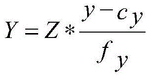
wherein X is a transverse position corresponding to each test image; y is longitudinal position information corresponding to each test image; z is the position depth of the test image; (x, y) is the pixel position of the test image (x is the horizontal pixel position of the test image; y is the vertical pixel position of the test image); c. CxAnd cyIs the optical center of the image acquisition device; f. ofxAnd fyIs the focal length of the image capture device.
And splicing the test images into a three-dimensional point cloud map according to the position coordinates of the test images, wherein the three-dimensional point cloud map comprises a three-dimensional barrier area.
Further, after the three-dimensional position information corresponding to each test image is generated, because the test image acquires obstacle information (such as a static obstacle or a dynamic obstacle) on or around the test topological path, whether each test image contains the static obstacle or not is determined, when the test image contains the static obstacle, the distance between the static obstacle and the position to which the robot belongs in the test image is determined, and then the static position information is determined according to the three-dimensional position information and the distance. In this way, the determination of the obstacle region in the subsequent step by the dynamic obstacle (the dynamic obstacle is moved continuously, so that the obstacle region may be deviated due to the dynamic obstacle being included in the obstacle region).
Further, after static position information is determined according to the three-dimensional position information and the distance, because the same static obstacle may exist in different test images, a three-dimensional obstacle area to which each static obstacle belongs can be determined according to each static position information, and each three-dimensional position information and each three-dimensional obstacle area are subjected to position stitching to obtain a three-dimensional point cloud map corresponding to the scene map; the three-dimensional point cloud map comprises three-dimensional position information of a test topological path under the scene and three-dimensional position information of an obstacle area.
Performing two-dimensional projection on the three-dimensional point cloud map to obtain a two-dimensional scene map; the two-dimensional scene map includes a two-dimensional obstacle region corresponding to the test topological path after the projection of the three-dimensional obstacle region.
Specifically, after the three-dimensional point cloud map contains a three-dimensional obstacle region, the three-dimensional point cloud map is subjected to two-dimensional projection to obtain a two-dimensional scene map containing the two-dimensional obstacle region corresponding to the test topological path after the three-dimensional obstacle region is projected. It can be understood that the two-dimensional projection is a method for converting three-dimensional position information in a three-dimensional point cloud map into two-dimensional position information.
Further, it is indicated in the above description that the three-dimensional position information includes horizontal coordinate information, vertical coordinate information, and position depth, and then the step of performing two-dimensional projection on the three-dimensional point cloud map is completed only after the vertical coordinate information is set to 0, and then a two-dimensional scene map including a two-dimensional obstacle area corresponding to the test topological path after the three-dimensional obstacle area projection is obtained.
Mapping the test topological path to the two-dimensional scene map to obtain the scene map, and recording the two-dimensional barrier region as a barrier region of the test topological path in the scene map.
Specifically, after the three-dimensional point cloud map is subjected to two-dimensional projection to obtain a two-dimensional scene map, the test topological path is mapped into the two-dimensional scene map to obtain the scene map, and the two-dimensional obstacle area is recorded as an obstacle area of the test topological path in the scene map.
In an embodiment, mapping the test topological path in the robot topological map to the two-dimensional scene map to obtain the scene map includes:
acquiring a path coordinate system corresponding to the test topological path; the path coordinate system represents two-dimensional coordinate information of any path point on the test topology path.
As can be appreciated, the path coordinate system refers to the position information of the topological path in the robot topological map; a path point refers to any point on the test topology path.
And acquiring a preset map scale factor corresponding to the two-dimensional scene map, obtaining scene map coordinate information corresponding to each path point according to the two-dimensional coordinate information of each path point and the preset map scale factor, and then generating the scene map according to the scene map coordinate information.
It is understood that the preset map scale factor refers to the image scale between the robot topology map and the two-dimensional scene map.
Specifically, after a path coordinate system corresponding to the topological path is acquired, a preset map scale factor corresponding to the two-dimensional scene map is acquired, and scene map coordinate information corresponding to each path point is acquired according to the two-dimensional coordinate information of each path point and the preset map scale factor, so that the scene map is acquired. Further, after the scene map is obtained, image filtering may be performed on the scene map to remove noise in the scene map, so as to prevent the noise in the scene map from affecting the acquisition of the width of the navigation path, and improve the accuracy of the acquisition of the width of the navigation path.
For example, assuming that the two-dimensional coordinate information of one of the waypoints is P (a, b), the horizontal coordinate a and the vertical coordinate b of the waypoint are divided by a preset map scale factor, and the two-dimensional coordinate information of the waypoint in the scene map is P1(a/scale, b/scale) (scale is the preset map scale factor).
S30: recording the topological road section where the real-time position information is located as a real-time topological road section, and generating a pixel growth line section perpendicular to the real-time topological road section at each preset position point on the real-time topological road section, wherein each pixel growth line section is the longest line section which does not touch the barrier area.
It can be understood that, in this embodiment, a plurality of preset position points are set on the real-time topological road segment, and pixel point location expansion is sequentially performed from each preset position point to the left and right sides of the preset position point, so that a pixel growth line segment perpendicular to the real-time topological road segment is generated at the preset position point. The pixel growth line segment refers to the longest line segment which is generated at a preset position point and does not touch the obstacle area; it is understood that there are a plurality of line segments that do not touch the obstacle area at a predetermined position point, and the pixel growth line segment is the longest line segment among the plurality of line segments that do not touch the obstacle area at the predetermined position point.
Further, pixel point expansion refers to presetting a pixel interval (which can be set according to requirements, such as setting for 1 pixel, 2 pixels, and the like), further generating a left pixel point at the pixel interval on the left side of a preset position point, and when the left pixel point does not touch an obstacle region, continuing to generate another left pixel point at the pixel interval on the left side of the left pixel point until the generated left pixel point touches the obstacle region; similarly, a right pixel point is generated at the pixel interval on the right side of the preset position point, and when the right pixel point does not touch the obstacle area, another right pixel point is continuously generated at the pixel interval on the right side of the right pixel point until the generated right pixel point touches the obstacle area. And when the robot runs from the starting end to the terminal end of the real-time topological road section, the left side of the robot is the left side of the definition, and the right side of the robot is the right side of the definition.
In an embodiment, in step S30, that is, the generating a pixel growth line segment perpendicular to the real-time topological segment at each preset position point on the real-time topological segment includes:
and generating interval position points between the two end points of the real-time topological road section, and recording the two end points of the real-time topological road section and each interval position point as the preset position point.
It is understood that there are two endpoints (i.e., a start endpoint and a clock endpoint) for each real-time topology segment. Further, the interval position points may be selected through a preset selection interval, where the preset selection interval may be selected according to a requirement, and exemplarily, the preset selection interval may be one pixel, that is, one interval position point is generated every interval of one pixel; and then after interval position points are generated between the two end points of the real-time topological road section, recording the two end points of the real-time topological road section and each interval position point as a preset position point.
And starting from the preset position point, carrying out pixel point location expansion towards the direction of two opposite sides far away from the preset position point, and generating a pixel growth line segment corresponding to the preset position point.
Specifically, after two end points of the real-time topological road segment and each of the interval position points are recorded as the preset position point, pixel point location expansion is performed from the preset position point to a direction away from the preset position point from two opposite sides; if the robot drives from the start end (e.g., a1 in fig. 3) to the end (e.g., a5 in fig. 3) of the real-time topological road segment, the left side of the robot is the left side of the preset position point on the real-time topological road segment, and the right side of the robot is the right side of the preset position point on the real-time topological road segment; in this way, the pixel point location expansion also includes performing pixel point fetching on the right left side of the preset location point (the right left side is the left side of the preset location point and the direction parallel to the preset location point), and performing pixel point fetching on the right side of the preset location point (the right side is the right side of the preset location point and the direction parallel to the preset location point), so as to generate a pixel growth line segment corresponding to the preset location point.
In an embodiment, the performing pixel point location expansion from the preset position point to a direction away from the preset position point from opposite sides to generate a pixel growth line segment corresponding to the preset position point includes:
and according to a preset expansion distance, starting from the preset position point, carrying out pixel point expansion towards the direction far away from the preset position point from the two opposite sides to obtain a left pixel point and a right pixel point.
Optionally, the preset expansion distance may be selected according to expansion requirements, and exemplarily, the preset expansion distance may be one pixel point, two pixel points, and the like.
Specifically, after the topology section where the real-time position information is located is recorded as a real-time topology section, pixel point expansion is performed from the preset position point according to a preset expansion distance in a direction away from the preset position point to opposite sides, that is, pixel point expansion is performed to the left side of the preset position point (for example, a left-side point is generated at the preset expansion distance on the left side of the preset position point, and another point is generated at the preset expansion distance on the left side of the left-side point), and pixel point expansion is performed to the right side of the preset position point (for example, a right-side point is generated at the preset expansion distance on the right side of the preset position point, and another point is generated at the preset expansion distance on the right side of the right-side point), so that a left pixel point and a right pixel point are obtained.
And detecting whether the left pixel points touch the obstacle area, stopping pixel point expansion to the left side of the preset position point when the left pixel points touch the obstacle area, recording the left pixel points touching the obstacle area as left overlapped pixel points, and recording adjacent left pixel points in front of the left overlapped pixel points as left width points.
It can be understood that barrier regions may exist on both the left side and the right side of the real-time topological road section, and therefore whether a left pixel point touches the barrier region needs to be detected; judging whether the left pixel touches the obstacle area in this embodiment includes: one is as follows: whether the left pixel point is in the region of the obstacle or not; the second step is as follows: whether the left pixel point is overlapped with the boundary of the barrier area or not; if the left pixel point is located in the obstacle area or the boundary of the left pixel point and the obstacle area is overlapped, judging that the left pixel point touches the obstacle area, further stopping pixel point expansion to the left side of the preset position point when the left pixel point is detected to touch the obstacle area, recording the left pixel point touching the obstacle area as a left overlapped pixel point, and recording the adjacent left pixel point in front of the left overlapped pixel point as a left width point, wherein the left width point does not touch the obstacle area.
And detecting whether the right pixel points touch the obstacle area, stopping pixel point expansion of the preset position points to the right side when the right pixel points touch the obstacle area, recording the right pixel points touching the obstacle area as right overlapped pixel points, and recording adjacent right pixel points in front of the right overlapped pixel points as right width points.
It can be understood that barrier regions may exist on both the left side and the right side of the real-time topological road section, and therefore whether the right pixel points touch the barrier regions needs to be detected; judging whether the right pixel touches the obstacle area in the embodiment includes: one is as follows: whether the right pixel point is in the region of the obstacle or not; the second step is as follows: whether the right pixel point is overlapped with the boundary of the barrier area or not; if the right pixel point is located in the obstacle area or the right pixel point is overlapped with the boundary of the obstacle area, judging that the right pixel point touches the obstacle area, stopping pixel point expansion of the preset position point to the right side when the right pixel point is detected to touch the obstacle area, recording the right pixel point touching the obstacle area as a right overlapped pixel point, and recording the right pixel point which is in front of the right overlapped pixel point and adjacent to the right overlapped pixel point as a right width point, wherein the right width point does not touch the obstacle area.
And recording a connecting line between the left width point and the right width point as a pixel growth line segment corresponding to the preset position point.
Specifically, after the left width point and the right width point are determined, a connecting line between the left width point and the right width point is recorded as a pixel growth line segment corresponding to the preset position point.
Exemplarily, as shown in fig. 3, L1 is a real-time topology link, T is a robot, a1 and a5 are two ends of the real-time topology link (where a1 is a start end, a5 is a terminal end), and D is an obstacle area; a2 is one of the spaced location points generated between the two endpoints of the real-time topology road segment, that is, one of the preset location points, and taking the preset location point a2 as an example, pixel point expansion is performed on the left and right sides of the preset location point to obtain a left pixel point (for example, a pixel point on the left side of the preset location point a2 in fig. 3, A3 is a left pixel point that does not touch the obstacle region D) and a right pixel point (for example, a pixel point on the right side of the preset location point a2 in fig. 3, a4 is a right pixel point that does not touch the obstacle region D). Wherein, A3 is a left width point, and a4 is a right width point (as shown in fig. 3, if A3 continues to perform pixel point expansion to the left side, the expanded pixel point is in the barrier region, that is, a left overlapping pixel point, and if a4 continues to perform pixel point expansion to the right side, the expanded pixel point is also in the barrier region, that is, a right overlapping pixel point); further, the connection between the left width point A3 and the right width point a4 is L2, that is, L2 is a pixel growth line segment.
In one embodiment, after recording a left pixel point that precedes the left overlapping pixel point as a left width point, the processor when executing the computer readable instructions further performs the steps of:
and acquiring a first distance between the left width point and the obstacle area, and comparing the first distance with a preset minimum expansion distance threshold.
It is understood that the first pitch substantially refers to a length of a line segment between the left width point and a boundary of the obstacle region. In the above embodiment, it is pointed out that pixel point location expansion is performed by using a preset expansion distance, and the first distance between the left width point and the obstacle region may be wider (if the first distance is greater than two pixels and less than three pixels) due to a larger preset expansion distance (if the preset expansion distance is set to three pixels), so that the accuracy of a finally generated pixel growth line segment is lower, and therefore, in this embodiment, the first distance is compared with the preset minimum expansion distance threshold. The preset minimum extended distance threshold may be set according to a requirement, and exemplarily, the preset minimum extended distance threshold may be set to 1 pixel, and the like.
When the first distance is larger than or equal to the preset minimum extension distance threshold, adjusting the preset extension distance to be the minimum extension distance threshold.
And performing pixel expansion on the left side of the left width point according to the minimum expansion distance threshold to obtain an updated left width point, and updating the pixel growth line segment according to the updated left width point.
Specifically, after the first distance is compared with a preset minimum extension distance threshold, if the first distance is greater than or equal to the preset minimum extension distance threshold, the preset extension distance is adjusted to the minimum extension distance threshold, pixel point location extension is performed on the left side of the left width point according to the minimum extension distance threshold, an updated left width point is obtained (the updated left width point still does not touch the obstacle region), and a pixel growth line segment is updated according to the updated left width point (that is, a connection line between the updated left width point and the updated right width point is recorded as an updated pixel growth line segment).
Further, if the first distance is smaller than a preset minimum expansion distance threshold, the left width point is not updated; after the left width point is updated, it may be determined whether the update may be continued, and the update step is the same as the above step, that is, the left width point may be continuously updated subsequently, and details are not described herein again.
In one embodiment, after recording a right pixel point before the right overlapping pixel point as a right width point, the processor when executing the computer readable instructions further performs the steps of:
and acquiring a second distance between the right width point and the obstacle area, and comparing the second distance with a preset minimum expansion distance threshold.
It is understood that the second pitch substantially refers to a length of a line segment between the right width point and a boundary of the obstacle region. In the above embodiment, it is pointed out that pixel point location expansion is performed by using the preset expansion distance, and it may be that the second distance between the right width point and the obstacle region is wider (for example, when the second distance is greater than two pixels and less than three pixels) due to the fact that the preset expansion distance is set to be larger (for example, when the preset expansion distance is set to be three pixels), and then accuracy of a finally generated pixel growth line segment is lower, so that the second distance is compared with the preset minimum expansion distance threshold in this embodiment.
And when the second distance is greater than or equal to the preset minimum extension distance threshold, adjusting the preset extension distance to the minimum extension distance threshold.
And carrying out pixel point location expansion on the right width point to the right side according to the minimum expansion distance threshold to obtain an updated right width point, and updating the pixel growth line segment according to the updated right width point.
Specifically, after the second distance is compared with a preset minimum extension distance threshold, if the second distance is greater than or equal to the preset minimum extension distance threshold, the preset extension distance is adjusted to the minimum extension distance threshold, pixel point location extension is performed on the right width point to the left side according to the minimum extension distance threshold, an updated right width point is obtained (the updated right width point still does not touch the barrier region), and a pixel growth line segment is updated according to the updated right width point (that is, a connection line between the updated right width point and the updated left width point is recorded as an updated pixel growth line segment).
Further, if the second distance is smaller than the preset minimum expansion distance threshold, the right width point is not updated; if the left width point and the right width point are updated, updating the pixel growth line segment according to the updated left width point and the updated right width point; after the left width point is updated, it may be determined whether the update may be continued, and the update step is the same as the above step, that is, the left width point may be continuously updated subsequently, and details are not described herein again.
S40: and comparing the line segment length of each pixel growth line segment to obtain a pixel growth line segment with the shortest line segment length, and calculating the width of the navigation path to which the real-time topological road segment belongs by adopting a preset width mapping method according to the pixel growth line segment with the shortest line segment length.
The width of the navigation path is the driving range of the robot on the navigation path at the real-time position information, and the driving range cannot exceed the width of the navigation path, so that the driving range which does not collide with the obstacle can be determined for the robot in advance, and the driving safety of the robot is improved. The preset width mapping method is used for mapping the shortest pixel growth line segment to the width of the navigation path in the actual operation process of the robot.
Specifically, after a pixel growth line segment perpendicular to the real-time topological road segment is generated at each preset position point on the real-time topological road segment, the line segment length of each pixel growth line segment is obtained, the line segment lengths of the pixel growth line segments are sequenced, so that the pixel growth line segment with the shortest line segment length is determined, and the width of a navigation path to which the real-time topological road segment belongs is calculated by adopting a preset width mapping method according to the pixel growth line segment with the shortest line segment length, so that the robot can run in the width of the navigation path to safely pass through the navigation path; further, when the robot is running in the width of the navigation path and an obstacle is detected, the robot can execute an obstacle avoidance strategy to ensure the running safety of the robot.
In this embodiment, a pixel growth line segment perpendicular to the real-time topological road segment is generated at each preset position point on the real-time topological road segment by a pixel point location expansion method, and the pixel growth line segment on each preset position point does not touch the obstacle region, so that the driving width of the robot on the navigation path is determined according to the shortest pixel growth line segment, the accuracy and the efficiency of determining the driving width are improved, and further, the driving range is provided for the robot in real time, so that the robot can drive more smoothly on the navigation path according to the driving width provided in real time, and the driving flexibility of the robot is improved.
In an embodiment, after the width of the navigation path is calculated by using a preset width mapping method according to the maximum pixel expansion area, the processor executes the computer readable instructions to further implement the following steps:
and controlling the robot to run within the width of the navigation path, and detecting whether a new obstacle area exists in real time.
It is to be understood that the new obstacle region may indicate the presence of the new obstacle region by changing the position information of the obstacle region, for example, by changing the position information of an obstacle in the obstacle region, by generating a new obstacle in a region other than the obstacle region, by disappearing an obstacle in the obstacle region, or the like. Illustratively, the existence of a new obstacle region may include the following possibilities: one is as follows: a new obstacle is added in the obstacle area, so that the obstacle area is enlarged; the second step is as follows: the position of the obstacle in the obstacle region moves, and the obstacle region is reduced or the position thereof changes.
In a specific embodiment, the system for acquiring a navigation path width of a robot further includes an obstacle detection device installed on the robot, the obstacle detection device is connected to the processor in a communication manner, and the real-time detection of whether a new obstacle area exists in the topological section includes:
and detecting static obstacles and dynamic obstacles in real time in the running process of the robot through an obstacle detection device.
It is understood that the obstacle detection device is used for detecting obstacles in front of or around the current running road during the running process of the robot, and the obstacle detection device can be constructed based on an optical visual perception technology or based on an ultrasonic sensor and the like.
When the obstacle detection device detects a static obstacle, mapping a region corresponding to the static obstacle into a scene map and recording the region as a static obstacle region.
It is understood that a static obstacle refers to an obstacle that is not movable by itself, such as a table, a chair, a locker, etc. in a meal delivery robot scenario. The static obstacle area is an area where a detected static obstacle belongs in the scene map when the robot drives in the driving width range of the topological road section, and the number of the static obstacle areas may be one or more.
Specifically, after the obstacle detection device mounted on the robot body detects an obstacle during the running of the robot, if the obstacle detection device detects a static obstacle, a region corresponding to the static obstacle is mapped into a scene map, that is, a region to which the static obstacle belongs in reality is mapped into the scene map, so as to obtain a static obstacle region to which the static obstacle belongs in the scene map. The area corresponding to the static obstacle is mapped to the scene map, a scale factor conversion mode can be used for obtaining a scale conversion factor between the scene map and an actual scene (namely the robot topological map), and the area corresponding to the static obstacle is divided by the scale conversion factor, so that the static obstacle area of the static obstacle in the scene map can be obtained.
When the obstacle detection device detects a dynamic obstacle, mapping a region corresponding to the dynamic obstacle into a scene map and recording the region as an obstacle-free region.
Specifically, the obstacle detection device may detect a dynamic obstacle (e.g., a pedestrian, an object that can move by itself, such as another robot, etc.) in addition to a static obstacle, map an area corresponding to the dynamic obstacle into the scene map, and set an area including the dynamic obstacle in the scene map as an obstacle-free area, and since the dynamic obstacle occupies the road width only temporarily and does not occupy the road all the time, the obstacle-free area does not affect the calculation of the width of the navigation path in the scene map even if the dynamic obstacle is detected.
Determining an obstacle detection area from the obstacle-free area and the static obstacle area.
And comparing the pixel positions of the obstacle detection area and the obstacle area, and determining that a new obstacle area exists when the pixel positions of the obstacle detection area and the obstacle area are inconsistent.
Specifically, after the obstacle detection area is determined from the obstacle-free area and the static obstacle area, the obstacle detection area and the obstacle area are subjected to pixel position matching, and when the pixel positions of the obstacle detection area and the obstacle area do not coincide with each other, for example, the static obstacle moves, or the obstacle-free area replaces the obstacle area, it is possible to determine that a new obstacle area exists.
Further, as described in step S40, in the present invention, the navigation path width is determined by the left pixel region closest to the topological link and the overlapping portion between the right pixel region and the obstacle region, so that when the obstacle detection region is aligned with the obstacle region, it is possible to determine whether or not the updating occurs between the obstacle detection region and the obstacle region by confirming the obstacle region that is closest to the topological link and has the overlapping portion with the left pixel region and/or the right pixel region. For example, if there is an overlapping portion between the obstacle detection area and the second left pixel area and the obstacle detection area is the area closest to the left side of the topological link, it may be determined that there is a new obstacle area and the data processing efficiency may be improved.
And when a new obstacle area exists, updating the obstacle area corresponding to the topological road section in the scene map according to the new obstacle area.
Specifically, after detecting whether a new obstacle area exists in the topological road segment in real time, if the new obstacle area exists, the obstacle area is updated in the scene map according to the new obstacle area.
Generating an updated pixel growth line segment perpendicular to the real-time topological road segment at each preset position point on the real-time topological road segment; each pixel growth line segment is the longest line segment which is generated on the preset position point and does not touch the updated barrier region.
Specifically, after the barrier area corresponding to the topological road section is updated in the scene map according to the new barrier area, an updated pixel growth line segment perpendicular to the real-time topological road section is generated at each preset position point on the real-time topological road section.
And calculating the updating width of the navigation path to which the real-time topological road section belongs by adopting a preset width mapping method according to the updated and shortest pixel growth line section.
Specifically, after an updated pixel growth line segment perpendicular to the real-time topological road segment is generated at each preset position point on the real-time topological road segment, the updated pixel growth line segments are compared, and according to the updated and shortest pixel growth line segment, an updated width of the navigation path to which the real-time topological road segment belongs is calculated by adopting a preset width mapping method.
In one embodiment, a robot is provided, which includes the robot navigation path width acquisition system. The robot comprises a shell, wherein a memory and a processor in the robot navigation path width acquisition system are arranged in the shell to protect the memory and the processor, so that the service lives of the memory and the processor are prolonged; the obstacle detection device in the robot navigation path width acquisition system is arranged on the shell so as to detect obstacles in the running process of the robot, and the obstacle detection device is in communication connection with the processor; an image acquisition device in the robot navigation path width acquisition system is arranged on the shell to acquire a test image in the running process of the robot so as to generate a scene map according to the test image, and the image acquisition device is in communication connection with the processor.
In an embodiment, as shown in fig. 2, a method for obtaining a robot navigation path width is provided, where the method for obtaining a robot navigation path width corresponds to a system for obtaining a robot navigation path width in the foregoing embodiment one to one, and the method for obtaining a robot navigation path width is applied to the system for obtaining a robot navigation path width, and the method for obtaining a robot navigation path width includes the following steps:
s10: acquiring real-time position information of the robot in the navigation path; the navigation path comprises at least one topological section;
s20: mapping the real-time position information into a scene map; an obstacle area is marked on the scene map;
s30: recording the topological road section where the real-time position information is located as a real-time topological road section, and generating a pixel growth line section perpendicular to the real-time topological road section at each preset position point on the real-time topological road section, wherein each pixel growth line section is the longest line section which does not touch the barrier area;
s40: and comparing the line segment length of each pixel growth line segment to obtain a pixel growth line segment with the shortest line segment length, and calculating the width of the navigation path to which the real-time topological road segment belongs by adopting a preset width mapping method according to the pixel growth line segment with the shortest line segment length.
In this embodiment, a pixel growth line segment perpendicular to the real-time topological road segment is generated at each preset position point on the real-time topological road segment by a pixel point location expansion method, and the pixel growth line segment on each preset position point does not touch the obstacle region, so that the driving width of the robot on the navigation path is determined according to the shortest pixel growth line segment, the accuracy and the efficiency of determining the driving width are improved, and further, the driving range is provided for the robot in real time, so that the robot can drive more smoothly on the navigation path according to the driving width provided in real time, and the driving flexibility of the robot is improved.
In an embodiment, the generating a pixel growth line segment perpendicular to the real-time topological road segment at each preset position point on the real-time topological road segment includes:
generating interval position points between two end points of the real-time topological road section, and recording the two end points of the real-time topological road section and each interval position point as the preset position point;
and starting from the preset position point, carrying out pixel point location expansion towards the direction of two opposite sides far away from the preset position point, and generating a pixel growth line segment corresponding to the preset position point.
In an embodiment, the performing pixel point location expansion from the preset position point to a direction away from the preset position point from opposite sides to generate a pixel growth line segment corresponding to the preset position point includes:
starting from the preset position point according to a preset expansion distance, and performing pixel point expansion in a direction away from the preset position point from two opposite sides to obtain a left pixel point and a right pixel point;
detecting whether the left pixel points touch the obstacle area, stopping pixel point expansion to the left side of the preset position point when the left pixel points touch the obstacle area, recording the left pixel points touching the obstacle area as left overlapped pixel points, and recording adjacent left pixel points in front of the left overlapped pixel points as left width points;
detecting whether the right pixel points touch the obstacle area, stopping pixel point expansion of the preset position points to the right side when the right pixel points touch the obstacle area, recording right pixel points touching the obstacle area as right overlapped pixel points, and recording adjacent right pixel points in front of the right overlapped pixel points as right width points;
and recording a connecting line between the left width point and the right width point as a pixel growth line segment corresponding to the preset position point.
In an embodiment, said recording a left pixel point that is one left pixel point before said left overlapped pixel point as a left width point further comprises:
acquiring a first distance between the left width point and the obstacle area, and comparing the first distance with a preset minimum expansion distance threshold;
when the first distance is larger than or equal to the preset minimum extension distance threshold, adjusting the preset extension distance to be the minimum extension distance threshold;
and performing pixel point location expansion on the left side of the left width point according to the minimum expansion distance threshold to obtain an updated left width point, and updating the pixel growth line segment according to the updated left width point.
In an embodiment, after recording a right pixel point before the right overlapping pixel point as a right width point, the method further includes:
acquiring a second distance between the right width point and the obstacle area, and comparing the second distance with a preset minimum expansion distance threshold;
when the second distance is greater than or equal to the preset minimum extension distance threshold, adjusting the preset extension distance to be the minimum extension distance threshold;
and carrying out pixel point location expansion on the right width point to the right side according to the minimum expansion distance threshold to obtain an updated right width point, and updating the pixel growth line segment according to the updated right width point.
In an embodiment, the calculating, according to the shortest pixel growth line segment, the width of the navigation path to which the real-time topological road segment belongs by using a preset width mapping method includes:
acquiring and recording the left width point corresponding to the shortest pixel growth line segment as a shortest left width point and the right width point corresponding to the shortest pixel growth line segment as a shortest right width point;
recording a preset position point contained in the shortest pixel growth line segment as a shortest position point, and determining a left pixel value of the shortest left width point from the shortest position point and a right pixel value of the shortest right width point from the shortest position point;
and recording the sum of the left pixel value and the right pixel value as a width pixel value, and calculating the width of the navigation path by adopting a preset width mapping method according to the width pixel value.
In an embodiment, before mapping the real-time location information into the scene map, the method further includes the following steps:
when the robot is controlled to run according to a test topological path, a plurality of test images of the robot on the test topological path are obtained through an image obtaining device; one of said test images having a location coordinate;
according to the position coordinates of the test images, the test images are spliced into a three-dimensional point cloud map, and the three-dimensional point cloud map comprises three-dimensional barrier areas;
performing two-dimensional projection on the three-dimensional point cloud map to obtain a two-dimensional scene map; the two-dimensional scene map comprises a two-dimensional barrier region corresponding to the test topological path after the three-dimensional barrier region is projected;
mapping the test topological path to the two-dimensional scene map to obtain the scene map, and recording the two-dimensional barrier region as a barrier region of the test topological path in the scene map.
In an embodiment, the mapping the test topological path to the two-dimensional scene map by using a preset path mapping method to obtain the scene map includes:
acquiring a path coordinate system corresponding to the test topological path; the path coordinate system represents two-dimensional coordinate information of any path point on the test topology path;
and acquiring a preset map scale factor corresponding to the two-dimensional scene map, obtaining scene map coordinate information corresponding to each path point according to the two-dimensional coordinate information of each path point and the preset map scale factor, and then generating the scene map according to the scene map coordinate information.
In an embodiment, after the calculating, according to the shortest pixel growth line segment, the width of the navigation path to which the real-time topological road segment belongs by using a preset width mapping method, the method further includes:
controlling the robot to run within the width of the navigation path, and detecting whether a new obstacle area exists in real time;
updating the obstacle area in the scene map according to a new obstacle area when the new obstacle area exists;
generating an updated pixel growth line segment perpendicular to the real-time topological road segment at each preset position point on the real-time topological road segment; each pixel growth line segment is the longest line segment which is generated on the preset position point and does not touch the updated barrier region;
and calculating the updating width of the navigation path to which the real-time topological road section belongs by adopting a preset width mapping method according to the updated and shortest pixel growth line section.
In an embodiment, the detecting whether a new obstacle area exists in the real-time topological road segment in real time includes:
detecting static obstacles and dynamic obstacles in real time in the running process of the robot through the obstacle detection device;
when the obstacle detection device detects a static obstacle, mapping a region corresponding to the static obstacle into the scene map and recording the region as a static obstacle region;
when the obstacle detection device detects a dynamic obstacle, mapping a region corresponding to the dynamic obstacle into the scene map and recording the region as an obstacle-free region;
determining an obstacle detection area according to the obstacle-free area and the static obstacle area;
and comparing the pixel positions of the obstacle detection area and the obstacle area, and determining that a new obstacle area exists when the pixel positions of the obstacle detection area and the obstacle area are inconsistent.
It should be understood that, the sequence numbers of the steps in the foregoing embodiments do not imply an execution sequence, and the execution sequence of each process should be determined by its function and inherent logic, and should not constitute any limitation to the implementation process of the embodiments of the present invention.
In one embodiment, a computer-readable storage medium is provided, on which a computer program is stored, which, when executed by a processor, implements the robot navigation path width acquisition method in the above-described embodiments.
It will be understood by those skilled in the art that all or part of the processes of the methods of the embodiments described above can be implemented by hardware instructions of a computer program, which can be stored in a non-volatile computer-readable storage medium, and when executed, can include the processes of the embodiments of the methods described above. Any reference to memory, storage, database, or other medium used in the embodiments provided herein may include non-volatile and/or volatile memory, among others. Non-volatile memory can include read-only memory (ROM), Programmable ROM (PROM), Electrically Programmable ROM (EPROM), Electrically Erasable Programmable ROM (EEPROM), or flash memory. Volatile memory can include Random Access Memory (RAM) or external cache memory. By way of illustration and not limitation, RAM is available in a variety of forms such as Static RAM (SRAM), Dynamic RAM (DRAM), Synchronous DRAM (SDRAM), Double Data Rate SDRAM (DDRSDRAM), Enhanced SDRAM (ESDRAM), Synchronous Link DRAM (SLDRAM), Rambus Direct RAM (RDRAM), direct bus dynamic RAM (DRDRAM), and memory bus dynamic RAM (RDRAM).
It will be apparent to those skilled in the art that, for convenience and brevity of description, only the above-mentioned division of the functional units and modules is illustrated, and in practical applications, the above-mentioned function distribution may be performed by different functional units and modules according to needs, that is, the internal structure of the apparatus is divided into different functional units or modules to perform all or part of the above-mentioned functions.
The above-mentioned embodiments are only used for illustrating the technical solutions of the present invention, and not for limiting the same; although the present invention has been described in detail with reference to the foregoing embodiments, it will be understood by those of ordinary skill in the art that: the technical solutions described in the foregoing embodiments may still be modified, or some technical features may be equivalently replaced; such modifications and substitutions do not substantially depart from the spirit and scope of the embodiments of the present invention, and are intended to be included within the scope of the present invention.
Claims (15)
1. A robot navigation path width acquisition system comprising a memory, a processor, and computer program computer readable instructions stored in the memory and executable on the processor, wherein the processor when executing the computer readable instructions performs the steps of:
acquiring real-time position information of a robot in a navigation path, wherein the navigation path comprises at least one topological road section;
mapping the real-time position information into a scene map; an obstacle area is marked on the scene map;
recording the topological road section where the real-time position information is located as a real-time topological road section, and generating a pixel growth line section perpendicular to the real-time topological road section at each preset position point on the real-time topological road section, wherein each pixel growth line section is the longest line section which does not touch the barrier area;
and comparing the line segment length of each pixel growth line segment to obtain a pixel growth line segment with the shortest line segment length, and calculating the width of the navigation path to which the real-time topological road segment belongs by adopting a preset width mapping method according to the pixel growth line segment with the shortest line segment length.
2. The robot navigation path width acquisition system of claim 1, wherein the generating a pixel growth line segment perpendicular to the real-time topological road segment at each preset position point on the real-time topological road segment comprises:
generating interval position points between two end points of the real-time topological road section, and recording the two end points of the real-time topological road section and each interval position point as the preset position point;
and starting from the preset position point, carrying out pixel point location expansion towards the direction of two opposite sides far away from the preset position point, and generating a pixel growth line segment corresponding to the preset position point.
3. The system for acquiring the navigation path width of the robot according to claim 2, wherein the pixel point location expansion from the preset position point to the direction away from the preset position point from the two opposite sides to generate a pixel growth line segment corresponding to the preset position point comprises:
according to a preset expansion distance, pixel point location expansion is carried out from the preset position point to the direction far away from the preset position point from the two opposite sides, and a left pixel point and a right pixel point are obtained;
detecting whether the left pixel points touch the obstacle area, stopping pixel point expansion to the left side of the preset position point when the left pixel points touch the obstacle area, recording the left pixel points touching the obstacle area as left overlapped pixel points, and recording adjacent left pixel points in front of the left overlapped pixel points as left width points;
detecting whether the right pixel points touch the obstacle area, stopping pixel point expansion of the preset position points to the right side when the right pixel points touch the obstacle area, recording right pixel points touching the obstacle area as right overlapped pixel points, and recording adjacent right pixel points in front of the right overlapped pixel points as right width points;
and recording a connecting line between the left width point and the right width point as a pixel growth line segment corresponding to the preset position point.
4. The robotic navigation path width acquisition system according to claim 3, wherein after recording a left pixel point that precedes the left overlapping pixel point as a left width point, the processor when executing the computer readable instructions further performs the steps of:
acquiring a first distance between the left width point and the obstacle area, and comparing the first distance with a preset minimum expansion distance threshold;
when the first distance is larger than or equal to the preset minimum extension distance threshold, adjusting the preset extension distance to be the minimum extension distance threshold;
and performing pixel point location expansion on the left side of the left width point according to the minimum expansion distance threshold to obtain an updated left width point, and updating the pixel growth line segment according to the updated left width point.
5. The robotic navigation path width acquisition system according to claim 3, wherein after recording a right pixel point preceding the right overlapping pixel point as a right width point, the processor when executing the computer readable instructions further performs the steps of:
acquiring a second distance between the right width point and the obstacle area, and comparing the second distance with a preset minimum expansion distance threshold;
when the second distance is greater than or equal to the preset minimum extension distance threshold, adjusting the preset extension distance to be the minimum extension distance threshold;
and carrying out pixel point location expansion on the right width point to the right side according to the minimum expansion distance threshold to obtain an updated right width point, and updating the pixel growth line segment according to the updated right width point.
6. The system for obtaining the width of the navigation path of the robot according to claim 3, wherein the calculating the width of the navigation path to which the real-time topological section belongs by using a preset width mapping method according to the shortest pixel growth line segment comprises:
acquiring and recording the left width point corresponding to the shortest pixel growth line segment as a shortest left width point and the right width point corresponding to the shortest pixel growth line segment as a shortest right width point;
recording a preset position point contained in the shortest pixel growth line segment as a shortest position point, and determining a left pixel value of the shortest left width point from the shortest position point and a right pixel value of the shortest right width point from the shortest position point;
and recording the sum of the left pixel value and the right pixel value as a width pixel value, and calculating the width of the navigation path by adopting a preset width mapping method according to the width pixel value.
7. The robot navigation path width acquisition system of claim 1, further comprising an image acquisition device mounted on the robot; the image acquisition device is in communication connection with the processor;
before mapping the real-time location information into a scene map, the processor executing the computer-readable instructions further comprises:
when the robot is controlled to run according to a test topological path, a plurality of test images of the robot on the test topological path are obtained through the image obtaining device; one of said test images having a location coordinate;
according to the position coordinates of the test images, the test images are spliced into a three-dimensional point cloud map, and the three-dimensional point cloud map comprises three-dimensional barrier areas;
performing two-dimensional projection on the three-dimensional point cloud map to obtain a two-dimensional scene map; the two-dimensional scene map comprises a two-dimensional barrier region corresponding to the test topological path after the three-dimensional barrier region is projected;
mapping the test topological path to the two-dimensional scene map to obtain the scene map, and recording the two-dimensional barrier region as a barrier region of the test topological path in the scene map.
8. The system according to claim 7, wherein the mapping the test topological path into the two-dimensional scene map by a preset path mapping method to obtain the scene map comprises:
acquiring a path coordinate system corresponding to the test topological path; the path coordinate system represents two-dimensional coordinate information of any path point on the test topology path;
and acquiring a preset map scale factor corresponding to the two-dimensional scene map, obtaining scene map coordinate information corresponding to each path point according to the two-dimensional coordinate information of each path point and the preset map scale factor, and then generating the scene map according to the scene map coordinate information.
9. The system according to claim 1, wherein after the preset width mapping method is used to calculate the width of the navigation path to which the real-time topological section belongs according to the shortest pixel growth line segment, the processor executes the computer-readable instructions and further comprises the following steps:
controlling the robot to run within the width of the navigation path, and detecting whether a new obstacle area exists in real time;
updating the obstacle area in the scene map according to a new obstacle area when the new obstacle area exists;
generating an updated pixel growth line segment perpendicular to the real-time topological road segment at each preset position point on the real-time topological road segment; each pixel growth line segment is the longest line segment which is generated on the preset position point and does not touch the updated barrier region;
and calculating the updating width of the navigation path to which the real-time topological road section belongs by adopting a preset width mapping method according to the updated and shortest pixel growth line section.
10. The robot navigation path width acquisition system of claim 9, further comprising an obstacle detection device mounted on the robot; the obstacle detection device is in communication connection with the processor;
the real-time detection of whether a new obstacle area exists in the real-time topological road section includes:
detecting static obstacles and dynamic obstacles in real time in the running process of the robot through the obstacle detection device;
when the obstacle detection device detects a static obstacle, mapping a region corresponding to the static obstacle into the scene map and recording the region as a static obstacle region;
when the obstacle detection device detects a dynamic obstacle, mapping a region corresponding to the dynamic obstacle into the scene map and recording the region as an obstacle-free region;
determining an obstacle detection area according to the obstacle-free area and the static obstacle area;
and comparing the pixel positions of the obstacle detection area and the obstacle area, and determining that a new obstacle area exists when the pixel positions of the obstacle detection area and the obstacle area are inconsistent.
11. A robot comprising the robot navigation path width acquisition system according to any one of claims 1 to 10.
12. A robot navigation path width acquisition method is characterized by comprising the following steps:
acquiring real-time position information of a robot in a navigation path, wherein the navigation path comprises at least one topological road section;
mapping the real-time position information into a scene map; an obstacle area is marked on the scene map;
recording the topological road section where the real-time position information is located as a real-time topological road section, and generating a pixel growth line section perpendicular to the real-time topological road section at each preset position point on the real-time topological road section, wherein each pixel growth line section is the longest line section which does not touch the barrier area;
and comparing the line segment length of each pixel growth line segment to obtain a pixel growth line segment with the shortest line segment length, and calculating the width of the navigation path to which the real-time topological road segment belongs by adopting a preset width mapping method according to the pixel growth line segment with the shortest line segment length.
13. The robot navigation path width acquisition method according to claim 12, wherein the generating a pixel growth line segment perpendicular to the real-time topological section at each preset position point on the real-time topological section includes:
generating interval position points between two end points of the real-time topological road section, and recording the two end points of the real-time topological road section and each interval position point as the preset position point;
and starting from the preset position point, carrying out pixel point location expansion towards the direction of two opposite sides far away from the preset position point, and generating a pixel growth line segment corresponding to the preset position point.
14. The method for obtaining the width of the navigation path of the robot according to claim 13, wherein the step of performing pixel point location expansion from the preset position point to a direction away from the preset position point from opposite sides to generate a pixel growth line segment corresponding to the preset position point comprises:
according to a preset expansion distance, pixel point location expansion is carried out from the preset position point to the direction far away from the preset position point from the two opposite sides, and a left pixel point and a right pixel point are obtained;
detecting whether the left pixel points touch the obstacle area, stopping pixel point expansion to the left side of the preset position point when the left pixel points touch the obstacle area, recording the left pixel points touching the obstacle area as left overlapped pixel points, and recording adjacent left pixel points in front of the left overlapped pixel points as left width points;
detecting whether the right pixel points touch the obstacle area, stopping pixel point expansion of the preset position points to the right side when the right pixel points touch the obstacle area, recording right pixel points touching the obstacle area as right overlapped pixel points, and recording adjacent right pixel points in front of the right overlapped pixel points as right width points;
and recording a connecting line between the left width point and the right width point as a pixel growth line segment corresponding to the preset position point.
15. A computer-readable storage medium storing a computer program, wherein the computer program is executed by a processor to implement the robot navigation path width acquisition method according to any one of claims 12 to 14.
Priority Applications (1)
| Application Number | Priority Date | Filing Date | Title |
|---|---|---|---|
| CN202111165820.2A CN113932825B (en) | 2021-09-30 | 2021-09-30 | Robot navigation path width acquisition system, method, robot and storage medium |
Applications Claiming Priority (1)
| Application Number | Priority Date | Filing Date | Title |
|---|---|---|---|
| CN202111165820.2A CN113932825B (en) | 2021-09-30 | 2021-09-30 | Robot navigation path width acquisition system, method, robot and storage medium |
Publications (2)
| Publication Number | Publication Date |
|---|---|
| CN113932825A true CN113932825A (en) | 2022-01-14 |
| CN113932825B CN113932825B (en) | 2024-04-09 |
Family
ID=79277862
Family Applications (1)
| Application Number | Title | Priority Date | Filing Date |
|---|---|---|---|
| CN202111165820.2A Active CN113932825B (en) | 2021-09-30 | 2021-09-30 | Robot navigation path width acquisition system, method, robot and storage medium |
Country Status (1)
| Country | Link |
|---|---|
| CN (1) | CN113932825B (en) |
Cited By (2)
| Publication number | Priority date | Publication date | Assignee | Title |
|---|---|---|---|---|
| CN114625131A (en) * | 2022-02-28 | 2022-06-14 | 深圳市普渡科技有限公司 | Road width determination method and device and robot |
| CN116540776A (en) * | 2023-06-05 | 2023-08-04 | 深圳市华赛睿飞智能科技有限公司 | Unmanned aerial vehicle vision obstacle avoidance method and system |
Citations (13)
| Publication number | Priority date | Publication date | Assignee | Title |
|---|---|---|---|---|
| JP2000230834A (en) * | 1999-02-10 | 2000-08-22 | Daihatsu Motor Co Ltd | Updating equipment of road map information and its control method |
| JP2001022934A (en) * | 1999-07-07 | 2001-01-26 | Tokai Rika Co Ltd | Method and device for recognizing travel road for vehicle |
| CN106092102A (en) * | 2016-07-20 | 2016-11-09 | 广州极飞电子科技有限公司 | A kind of unmanned plane paths planning method and device |
| CN109074668A (en) * | 2018-08-02 | 2018-12-21 | 深圳前海达闼云端智能科技有限公司 | Method for path navigation, relevant apparatus and computer readable storage medium |
| CN109427062A (en) * | 2017-08-30 | 2019-03-05 | 深圳星行科技有限公司 | Roadway characteristic labeling method, device, computer equipment and readable storage medium storing program for executing |
| CN109947109A (en) * | 2019-04-02 | 2019-06-28 | 北京石头世纪科技股份有限公司 | Robot working area map construction method and device, robot and medium |
| CN109974725A (en) * | 2017-12-28 | 2019-07-05 | 北京三快在线科技有限公司 | A kind of road network topology construction method, guidance path calculation method and device |
| CN109978925A (en) * | 2017-12-27 | 2019-07-05 | 深圳市优必选科技有限公司 | Robot pose recognition method and robot thereof |
| CN110146090A (en) * | 2019-06-26 | 2019-08-20 | 张收英 | Robot keeps right air navigation aid and the robot of walking |
| CN111220157A (en) * | 2020-01-10 | 2020-06-02 | 重庆康爵特智能科技有限公司 | Navigation path planning method based on region segmentation and computer readable storage medium |
| CN111595356A (en) * | 2020-04-27 | 2020-08-28 | 珠海市一微半导体有限公司 | Method for constructing working area of laser navigation robot |
| CN112020461A (en) * | 2018-04-27 | 2020-12-01 | 图森有限公司 | System and method for determining a distance from a vehicle to a lane |
| JP2021105963A (en) * | 2019-12-27 | 2021-07-26 | アマノ株式会社 | Autonomous travel work device |
-
2021
- 2021-09-30 CN CN202111165820.2A patent/CN113932825B/en active Active
Patent Citations (13)
| Publication number | Priority date | Publication date | Assignee | Title |
|---|---|---|---|---|
| JP2000230834A (en) * | 1999-02-10 | 2000-08-22 | Daihatsu Motor Co Ltd | Updating equipment of road map information and its control method |
| JP2001022934A (en) * | 1999-07-07 | 2001-01-26 | Tokai Rika Co Ltd | Method and device for recognizing travel road for vehicle |
| CN106092102A (en) * | 2016-07-20 | 2016-11-09 | 广州极飞电子科技有限公司 | A kind of unmanned plane paths planning method and device |
| CN109427062A (en) * | 2017-08-30 | 2019-03-05 | 深圳星行科技有限公司 | Roadway characteristic labeling method, device, computer equipment and readable storage medium storing program for executing |
| CN109978925A (en) * | 2017-12-27 | 2019-07-05 | 深圳市优必选科技有限公司 | Robot pose recognition method and robot thereof |
| CN109974725A (en) * | 2017-12-28 | 2019-07-05 | 北京三快在线科技有限公司 | A kind of road network topology construction method, guidance path calculation method and device |
| CN112020461A (en) * | 2018-04-27 | 2020-12-01 | 图森有限公司 | System and method for determining a distance from a vehicle to a lane |
| CN109074668A (en) * | 2018-08-02 | 2018-12-21 | 深圳前海达闼云端智能科技有限公司 | Method for path navigation, relevant apparatus and computer readable storage medium |
| CN109947109A (en) * | 2019-04-02 | 2019-06-28 | 北京石头世纪科技股份有限公司 | Robot working area map construction method and device, robot and medium |
| CN110146090A (en) * | 2019-06-26 | 2019-08-20 | 张收英 | Robot keeps right air navigation aid and the robot of walking |
| JP2021105963A (en) * | 2019-12-27 | 2021-07-26 | アマノ株式会社 | Autonomous travel work device |
| CN111220157A (en) * | 2020-01-10 | 2020-06-02 | 重庆康爵特智能科技有限公司 | Navigation path planning method based on region segmentation and computer readable storage medium |
| CN111595356A (en) * | 2020-04-27 | 2020-08-28 | 珠海市一微半导体有限公司 | Method for constructing working area of laser navigation robot |
Non-Patent Citations (2)
| Title |
|---|
| 丁磊 等: ""利用邻域质心投票从分类后影像提取道路中心线"", 《中国图象图形学报》, no. 11, 31 December 2015 (2015-12-31), pages 1526 - 1534 * |
| 艾青: ""基于视觉的AGV转向模型和控制研究"", 《信息科技辑》, no. 3, 15 March 2012 (2012-03-15), pages 10 - 48 * |
Cited By (3)
| Publication number | Priority date | Publication date | Assignee | Title |
|---|---|---|---|---|
| CN114625131A (en) * | 2022-02-28 | 2022-06-14 | 深圳市普渡科技有限公司 | Road width determination method and device and robot |
| CN116540776A (en) * | 2023-06-05 | 2023-08-04 | 深圳市华赛睿飞智能科技有限公司 | Unmanned aerial vehicle vision obstacle avoidance method and system |
| CN116540776B (en) * | 2023-06-05 | 2023-11-07 | 深圳市华赛睿飞智能科技有限公司 | Unmanned aerial vehicle vision obstacle avoidance method and system |
Also Published As
| Publication number | Publication date |
|---|---|
| CN113932825B (en) | 2024-04-09 |
Similar Documents
| Publication | Publication Date | Title |
|---|---|---|
| EP3950235B1 (en) | Self-propelled robot path planning method, self-propelled robot and storage medium | |
| CN109813328B (en) | Driving path planning method and device and vehicle | |
| CN109765902B (en) | Unmanned vehicle driving reference line processing method and device and vehicle | |
| CN109186618B (en) | Map construction method and device, computer equipment and storage medium | |
| CN113932825A (en) | Robot navigation path width acquisition system, method, robot and storage medium | |
| US11561103B2 (en) | Lane network data generation apparatus and storage medium | |
| CN113607161B (en) | Robot navigation path width acquisition system, method, robot and storage medium | |
| EP3113150A1 (en) | Local location computation device and local location computation method | |
| CN112356027B (en) | Obstacle avoidance method and device for agriculture and forestry robot, computer equipment and storage medium | |
| JP2020067698A (en) | Partition line detector and partition line detection method | |
| JP7095559B2 (en) | Bound line detection device and lane marking method | |
| CN111762519A (en) | Method and system for guiding picking robot operation and scheduling device | |
| CN115609594B (en) | Planning method and device for mechanical arm path, upper control end and storage medium | |
| CN109522779A (en) | Image processing apparatus | |
| JP2020118575A (en) | Inter-vehicle distance measurement device, error model generation device, learning model generation device, and method and program thereof | |
| JP6398218B2 (en) | Self-position calculation device and self-position calculation method | |
| CN116342745A (en) | Editing method and device for lane line data, electronic equipment and storage medium | |
| US11884303B2 (en) | Apparatus and method for determining lane change of surrounding objects | |
| CN114274117B (en) | Robot, obstacle-based robot interaction method, device and medium | |
| CN113741422B (en) | Robot topology map generation system, method, computer device and storage medium | |
| CN115562296B (en) | Robot scheduling method, system and device based on hybrid control strategy | |
| KR20160144848A (en) | Apparatus and method for controlling mobile robot | |
| US20230027659A1 (en) | Self-position estimation device, moving body, self-position estimation method, and self-position estimation program | |
| CN112904841B (en) | Non-horizontal single-line positioning obstacle avoidance method, device, equipment and storage medium | |
| CN112799387B (en) | Robot control method and device and robot |
Legal Events
| Date | Code | Title | Description |
|---|---|---|---|
| PB01 | Publication | ||
| PB01 | Publication | ||
| SE01 | Entry into force of request for substantive examination | ||
| SE01 | Entry into force of request for substantive examination | ||
| GR01 | Patent grant | ||
| GR01 | Patent grant |