CN113906875B - Laboratory is with small-size transplanter - Google Patents
Laboratory is with small-size transplanter Download PDFInfo
- Publication number
- CN113906875B CN113906875B CN202111216687.9A CN202111216687A CN113906875B CN 113906875 B CN113906875 B CN 113906875B CN 202111216687 A CN202111216687 A CN 202111216687A CN 113906875 B CN113906875 B CN 113906875B
- Authority
- CN
- China
- Prior art keywords
- clamping
- fumarole
- gag lever
- lever post
- mounting groove
- Prior art date
- Legal status (The legal status is an assumption and is not a legal conclusion. Google has not performed a legal analysis and makes no representation as to the accuracy of the status listed.)
- Active
Links
Images


Classifications
-
- A—HUMAN NECESSITIES
- A01—AGRICULTURE; FORESTRY; ANIMAL HUSBANDRY; HUNTING; TRAPPING; FISHING
- A01C—PLANTING; SOWING; FERTILISING
- A01C11/00—Transplanting machines
- A01C11/02—Transplanting machines for seedlings
Landscapes
- Life Sciences & Earth Sciences (AREA)
- Soil Sciences (AREA)
- Environmental Sciences (AREA)
- Transplanting Machines (AREA)
Abstract
The invention discloses a small transplanter for laboratories, which comprises a rack, wherein a first air cylinder is vertically arranged on the rack, the piston end of the first air cylinder is hinged with two clamping arms, a positioning plate is fixed on the outer side of the first air cylinder, and the outer side of each clamping arm is connected with the positioning plate through a second air cylinder; the clamping arm is internally provided with a mounting groove, a plurality of first through holes communicated with the outer side of the clamping arm are formed in the mounting groove, a clamping mechanism is mounted in the mounting groove, and a fixing bolt penetrates through the first through holes to fix the clamping mechanism in the mounting groove; the inboard gag lever post that is fixed with through first connecting rod of centre gripping arm, the gag lever post parallels with the centre gripping arm, and the gag lever post is located the top of mounting groove, and the both sides edge on gag lever post surface is provided with a plurality of fumarole respectively, and the intermediate junction on gag lever post surface has the gasbag, is located the inside gag lever post surface of gasbag and is provided with the hole of aerifing. The invention can improve the defects of the prior art, and the transplanting process can effectively protect the seedlings.
Description
Technical Field
The invention relates to a crop cultivation laboratory device, in particular to a small transplanter for a laboratory.
Background
In a seedling breeding laboratory, bare-root seedling transplanting operation is frequently carried out. Because the existing automatic transplanting equipment is designed for field planting operation and is not suitable for being used in a laboratory, the manual transplanting operation not only consumes a large amount of manpower, but also has higher requirements on the proficiency of operators.
Disclosure of Invention
The invention aims to solve the technical problem of providing a small transplanter for laboratories, which can overcome the defects of the prior art, realize automatic transplanting of seedlings, effectively protect the seedlings in the transplanting process, avoid seedling damage and is suitable for being used in laboratories.
In order to solve the technical problems, the technical scheme adopted by the invention is as follows.
A small transplanter for laboratories comprises a rack, wherein a first cylinder is vertically arranged on the rack, the piston end of the first cylinder faces downwards, the piston end of the first cylinder is hinged with two clamping arms, a positioning plate is fixed on the outer side of the first cylinder, and the outer side of each clamping arm is connected with the positioning plate through a second cylinder; the clamping mechanism is arranged in the mounting groove, and a fixing bolt penetrates through the first through hole to fix the clamping mechanism in the mounting groove; the utility model discloses a pneumatic air compressor, including centre gripping arm, gag lever post, air bag, air pipe, solenoid valve, the gag lever post is inboard to be fixed with the gag lever post through first connecting rod, the gag lever post parallels with the centre gripping arm, the gag lever post is located the top of mounting groove, the both sides edge on gag lever post surface is provided with a plurality of fumarole respectively, the intermediate junction on gag lever post surface has the gasbag, the gag lever post surface that is located the gasbag inside is provided with aerifys the hole, fumarole and aerify the hole and be connected to the compressed air source through the trachea respectively, install the solenoid valve that is used for controlling two way trachea break-make on the trachea, the gasbag inboard is pasted and is had the elastic rubber strip.
Preferably, the clamping mechanism comprises a base, a threaded hole matched with the fixing bolt is formed in the bottom surface of the base, a sliding groove parallel to the clamping arm is formed in the top surface of the base, a sliding block is arranged in the sliding groove, two ends of the sliding block are connected with the sliding groove through second springs, a rubber layer is laid at the bottom of the sliding groove, a second through hole is formed in the sliding block, a second connecting rod is movably inserted in the second through hole, a first spring is arranged on the outer side of the second through hole and connected with the second connecting rod, and a clamping piece is connected to the top of the second connecting rod through a universal joint.
Preferably, the surface symmetry of clamping piece is provided with two arc deflectors, and the interval of two arc deflectors reduces gradually from top to bottom, and the arc deflector is connected with the elasticity extension plate towards the one end of below, and the clamping piece between two arc deflectors is fixed with the cushion on the surface.
Preferably, two supporting blocks are fixed on the inner side wall of the elastic extension plate, blocking pieces are axially connected to the supporting blocks, one ends, facing the edge of the elastic extension plate, of the blocking pieces are connected with the elastic extension plate through third springs, and gaps are formed between free ends of the two blocking pieces on the same elastic extension plate.
Preferably, the airbag comprises an airbag body, wherein flanges communicated with the airbag body are respectively arranged on two sides of the top and the bottom of the airbag body, and the flanges are positioned on the outer side of the airbag body in an inflated state.
Preferably, the both ends on gag lever post surface are provided with a plurality of side direction fumarole respectively, and the side direction fumarole is located the outside of fumarole, and the jet-propelled direction and the gag lever post surface vertical of fumarole, the jet-propelled direction of side direction fumarole are towards the outside of gag lever post to be 65 contained angles with the jet-propelled direction of fumarole, the side direction fumarole is connected on same trachea with the fumarole, is connected with flow control valve between fumarole and the trachea.
Preferably, both ends of the elastic rubber strip are positioned in the flanges.
Adopt the beneficial effect that above-mentioned technical scheme brought to lie in: because the invention is used for carrying out the bare-root seedling transplanting operation in small batch and accurately in a laboratory, a duckbilled suspended cup type transplanting mechanism which is common in the traditional field transplanting operation is not adopted, and the seedling is directly clamped and transplanted by the clamping arm. In order to effectively protect the stems and leaves of seedlings, the structure of the clamping arm is improved. Firstly, the upper part of the clamping arm is provided with the air bag for supporting and protecting the blade area of the seedling, the possibility of damage of the blade can be reduced in the transplanting process, the air jet holes are used for blowing the blade through air flow in the seedling clamping process so as to enable the blade to be far away from the vicinity of the limiting rod area, the blade is prevented from being extruded and damaged by the limiting rod or the air bag, the main stem of the seedling is clamped and fixed by the clamping mechanism at the lower part of the clamping arm, the vertical position of the clamping mechanism can be flexibly adjusted according to the size of the seedling, and the whole seedling is transplanted under the states of upper limiting protection and lower clamping fixation. Use the clamping piece to carry out the centre gripping to the seedling among the fixture, the clamping piece passes through universal joint and second connecting rod and installs on the slider, and the slider can realize the slip of limited distance in the spout to can cushion when the vertical effort between clamping piece and seedling increases in the twinkling of an eye, avoid the clamping piece to harm the surface of seedling stem. Along with the clamping-force increase between fixture and the seedling, the sliding friction between second connecting rod and the rubber layer also can increase in step to exert the damping to the slip of slider, avoid the slider to appear reciprocating rocking in the spout. The universal joint can lead the clamping piece to well clamp and fix the main stems at different angles. Because the top of centre gripping arm is articulated, the upper portion of clamping piece first contacts the seedling when the centre gripping seedling of event clamping piece, in order to reduce the probability of clamping piece centre gripping failure, has set up the arc deflector, carries out preliminary spacing direction to the position of seedling and clamping piece, then along with the closure of centre gripping arm, elasticity extension plate centre gripping seedling, and the realization is fixed to the horizontal centre gripping of seedling, and the cushion is used for protecting the seedling. After elasticity extension plate centre gripping seedling, the seedling pushes down the medial extremity of separation blade to make the outside end upwarp of separation blade, thereby make two separation blades on the same elasticity extension plate form one "sunk structure", the seedling realizes spacing fixedly in "sunk structure", sunk structure "can improve the stability to the horizontal centre gripping of seedling under the prerequisite that does not increase the damage seedling risk. The flanges at the two sides of the air bag body can be in lap joint with the lateral branches of the seedlings after being inflated, so that the flanges and the lateral branches can be matched with the clamping mechanism to apply force to the seedlings at multiple points in the transplanting process, and the main stems of the seedlings are further prevented from being damaged due to overlarge stress. Meanwhile, the air bags are used for limiting the effective lap joint of the seedlings, so that the seedlings can be prevented from shaking in the transplanting process, and the clamping stability of the clamping mechanism to the seedlings is improved.
Drawings
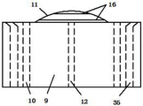
FIG. 1 is a block diagram of one embodiment of the present invention.
Fig. 2 is a structural view of a stopper rod according to an embodiment of the present invention.
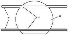
FIG. 3 is a block diagram of the inflated condition of the bladder in accordance with one embodiment of the present invention.
Fig. 4 is a schematic diagram of the gas circuit according to an embodiment of the present invention.
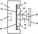
FIG. 5 is a block diagram of a clamping mechanism in accordance with one embodiment of the present invention.
Figure 6 is a block diagram of a clip according to an embodiment of the present invention.
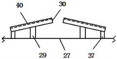
Fig. 7 is a mounting structure view of a baffle plate in an embodiment of the present invention.
Fig. 8 is a sectional structural view of a baffle plate in one embodiment of the invention.
Detailed Description
Referring to fig. 1-8, a specific embodiment of the present invention includes a frame 1, a first cylinder 2 is vertically installed on the frame 1, a piston end of the first cylinder 2 faces downward, a piston end of the first cylinder 2 is hinged with two clamping arms 3, a positioning plate 4 is fixed on an outer side of the first cylinder 2, and an outer side of each clamping arm 3 is connected with the positioning plate 4 through a second cylinder 42; the inner side of the clamping arm 3 is provided with a mounting groove 5, a plurality of first through holes 6 communicated with the outer side of the clamping arm 3 are arranged in the mounting groove 5, a clamping mechanism 7 is mounted in the mounting groove 5, and a fixing bolt 18 penetrates through the first through holes 6 to fix the clamping mechanism 7 in the mounting groove 5; the inboard gag lever post 9 that is fixed with through first connecting rod 8 of centre gripping arm 3, gag lever post 9 parallels with centre gripping arm 3, gag lever post 9 is located the top of mounting groove 5, the both sides edge on gag lever post 9 surface is provided with a plurality of fumarole 10 respectively, the intermediate junction on gag lever post 9 surface has gasbag 11, the gag lever post 9 surface that is located gasbag 11 inside is provided with aerifys hole 12, fumarole 10 and aerifys hole 12 and is connected to compressed air source 14 through trachea 13 respectively, install the solenoid valve 15 that is used for controlling two trachea 13 break-make on the trachea 13, gasbag 11 inboard is pasted and is had elastic rubber strip 16. Fixture 7 includes base 17, base 17 bottom surface is provided with and fixes bolt 18 matched with screw hole 19, base 17 top surface is provided with the spout 20 that parallels with centre gripping arm 3, slidable mounting has slider 21 in the spout 20, the slider 21 both ends are connected with spout 20 through second spring 32, rubber layer 22 has been laid to spout 20 bottom, be provided with second through-hole 23 on the slider 21, second through-hole 23 internalization is pegged graft and is had second connecting rod 24, the second through-hole 23 outside is provided with first spring 31, first spring 31 is connected with second connecting rod 24, second connecting rod 24 top is connected with clamping piece 25 through universal joint 38. Two arc-shaped guide plates 26 are symmetrically arranged on the surface of the clamping piece 25, the distance between the two arc-shaped guide plates 26 is gradually reduced from top to bottom, one end, facing the lower side, of each arc-shaped guide plate 26 is connected with an elastic extension plate 27, and a soft cushion 28 is fixed on the surface of the clamping piece 25 between the two arc-shaped guide plates 26. Two supporting blocks 29 are fixed on the inner side wall of the elastic extension plate 27, a blocking piece 30 is connected to the supporting blocks 29, one end, facing the edge of the elastic extension plate 27, of the blocking piece 30 is connected with the elastic extension plate 27 through a third spring 37, and a gap is formed between free ends of the two blocking pieces 30 on the same elastic extension plate 27. The airbag 11 includes an airbag body 33, and flanges 34 communicating with the airbag body 33 are provided on both sides of the top and bottom of the airbag body 33, respectively, the flanges 34 being located outside the airbag body 33 in an inflated state. The both ends on gag lever post 9 surface are provided with a plurality of side direction fumarole 35 respectively, and side direction fumarole 35 is located the outside of fumarole 10, and the jet-propelled direction and the gag lever post 9 surface vertical of fumarole 10, the jet-propelled direction of side direction fumarole 35 is towards the outside of gag lever post 9 to be 65 contained angles with the jet-propelled direction of fumarole 10, side direction fumarole 35 is connected on same trachea 13 with fumarole 10, is connected with flow control valve 36 between fumarole 10 and the trachea 13. The two ends of the elastic rubber strip 16 are located within the flanges 34.
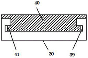
In addition, the surface of the blocking piece 30 is provided with a groove, the side wall of the groove is provided with a slot 39, a rubber sheet 40 is inserted in the groove, two sides of the rubber sheet 40 are provided with limiting parts 41 which are in inserted connection with the slot 39, and a gap is arranged between the limiting parts 41 and the bottom of the slot 39. By arranging the detachable rubber sheet 40 on the blocking sheet 30, different rubber sheets 40 can be selectively installed according to the types of seedlings and different transplanting requirements. Because separation blade 30 is located fixture 7 middle part, sets up sheet rubber 40 for the grafting installation, can be convenient for change the operation, meanwhile because separation blade 30 is thinner, sheet rubber 40 also can't set up great thickness, and sheet rubber 40 can utilize the deformation buffering of the clearance realization atress between the bottom of spacing portion 41 and slot 39 to improve sheet rubber 40's buffering effect.
The using method of the invention comprises the following steps: before transplanting operation, a proper first through hole 6 is selected to fix the clamping mechanism 7 according to requirements of seedlings and transplanting operation. After the transplanting operation starts, the piston end of the first cylinder 2 descends to drive the clamping arms 3 to descend to the clamping height, and meanwhile, the piston end of the second cylinder 42 ascends to open the two clamping arms 3. Then the piston end of the second cylinder 42 descends, the two clamping arms 3 are closed, and meanwhile, the air injection holes 10 and the lateral air injection holes 35 inject compressed air to blow and separate the leaves and the lateral branches of the seedlings, so that the limiting rods 9 slowly penetrate through the leaves and the lateral branches to be close to the main stem along with the closing process of the clamping arms 3. After the clamping piece 25 is contacted with the main stem of the seedling, the flow control valve 36 is closed, only the lateral air injection hole 35 is reserved for air injection, then the electromagnetic valve 15 communicated with the air inflation hole 12 is opened, the air bag 11 is inflated and expanded, after the air bag 11 is inflated, the electromagnetic valve 15 communicated with the lateral air injection hole 35 is closed, and the air injection of the lateral air injection hole 35 is stopped. With the closing of the clamping arm 3, the seedling stem enters the area between the two arc-shaped guide plates 26 and then is in compression joint with the elastic extension plate 27, the seedling stem presses the free end of the baffle 30 downwards, so that the outer end of the baffle 30 is tilted, and a 'concave structure' for accommodating the seedling stem is formed. After the seedlings are clamped and fixed, the seedlings are transplanted (the horizontal moving function in the transplanting process is completed by the frame 1 and can be realized by using a horizontal moving mechanism of the existing transplanter or other known equipment, which is not shown in the figure), then the air bag 11 is stopped to be inflated, the air bag 11 is contracted on the surface of the limiting rod 9 under the action of the contraction force of the elastic rubber strip 16, and then the clamping arm 3 is slowly opened, so that the rest seedlings of the clamping mechanism 7 are completely separated.
In the description of the present invention, it is to be understood that the terms "longitudinal", "lateral", "upper", "lower", "front", "rear", "left", "right", "vertical", "horizontal", "top", "bottom", "inner", "outer", etc., indicate orientations or positional relationships based on those shown in the drawings, and are used merely for convenience in describing the present invention, and do not indicate or imply that the device or element so referred to must have a particular orientation, be constructed and operated in a particular orientation, and thus, are not to be construed as limiting the present invention.
The foregoing shows and describes the general principles and features of the present invention, together with the advantages thereof. It will be understood by those skilled in the art that the present invention is not limited to the embodiments described above, which are given by way of illustration of the principles of the present invention, but that various changes and modifications may be made without departing from the spirit and scope of the invention, and such changes and modifications are within the scope of the invention as claimed. The scope of the invention is defined by the appended claims and equivalents thereof.
Claims (7)
1. The utility model provides a laboratory is with small-size transplanter which characterized in that: the clamping device comprises a rack (1), wherein a first cylinder (2) is vertically arranged on the rack (1), the piston end of the first cylinder (2) faces downwards, the piston end of the first cylinder (2) is hinged with two clamping arms (3), a positioning plate (4) is fixed on the outer side of the first cylinder (2), and the outer side of each clamping arm (3) is connected with the positioning plate (4) through a second cylinder (42); the inner side of the clamping arm (3) is provided with a mounting groove (5), a plurality of first through holes (6) communicated with the outer side of the clamping arm (3) are formed in the mounting groove (5), a clamping mechanism (7) is mounted in the mounting groove (5), and a fixing bolt (18) penetrates through the first through holes (6) to fix the clamping mechanism (7) in the mounting groove (5); a limiting rod (9) is fixed on the inner side of the clamping arm (3) through a first connecting rod (8), the limiting rod (9) is parallel to the clamping arm (3), the limiting rod (9) is located above the mounting groove (5), a plurality of air injection holes (10) are respectively formed in the edges of two sides of the surface of the limiting rod (9), an air bag (11) is connected to the middle of the surface of the limiting rod (9), air inflation holes (12) are formed in the surface of the limiting rod (9) located inside the air bag (11), the air injection holes (10) and the air inflation holes (12) are respectively connected to a compressed air source (14) through air pipes (13), electromagnetic valves (15) used for controlling the connection and disconnection of two air pipes (13) are installed on the air pipes (13), and elastic rubber strips (16) are adhered to the inner side of the air bag (11); the upper portion of centre gripping arm (3) adopts gasbag (11) to support the protection to the blade region of seedling, can reduce the impaired possibility of blade at the transplanting in-process, fumarole (10) are used for blowing the blade through the air current at the in-process of centre gripping seedling, make near the gag lever post region be kept away from to the blade, produce extrusion damage to the blade with avoid gag lever post (9) or gasbag (11), it is fixed to adopt fixture (7) to carry out the centre gripping to the stem of seedling in the lower part of centre gripping arm (3), position about fixture (7) can be adjusted according to the size flexibility of seedling, whole seedling is in upper portion spacing protection, the operation is transplanted under the fixed state of lower part centre gripping.
2. The laboratory mini-transplanter according to claim 1, wherein: the clamping mechanism (7) comprises a base (17), a threaded hole (19) matched with a fixing bolt (18) is formed in the bottom surface of the base (17), a sliding groove (20) parallel to the clamping arm (3) is formed in the top surface of the base (17), a sliding block (21) is installed in the sliding groove (20) in a sliding mode, two ends of the sliding block (21) are connected with the sliding groove (20) through second springs (32), a rubber layer (22) is laid at the bottom of the sliding groove (20), a second through hole (23) is formed in the sliding block (21), a second connecting rod (24) is movably inserted in the second through hole (23), a first spring (31) is arranged on the outer side of the second through hole (23), the first spring (31) is connected with the second connecting rod (24), and the top of the second connecting rod (24) is connected with a clamping piece (25) through a universal joint (38).
3. The laboratory mini-transplanter according to claim 2, wherein: the surperficial symmetry of clamping piece (25) is provided with two arc deflector (26), and the interval of two arc deflector (26) from top to bottom reduces gradually, and arc deflector (26) are connected with elasticity extension plate (27) towards the one end of below, and clamping piece (25) between two arc deflector (26) are fixed with cushion (28) on the surface.
4. The laboratory mini-transplanter according to claim 3, wherein: the elastic extension plate is characterized in that two supporting blocks (29) are fixed on the inner side wall of the elastic extension plate (27), blocking pieces (30) are connected to the supporting blocks (29) in a shaft mode, one ends, facing the edge of the elastic extension plate (27), of the blocking pieces (30) are connected with the elastic extension plate (27) through third springs (37), and gaps are formed between free ends of the two blocking pieces (30) on the same elastic extension plate (27).
5. The laboratory mini-transplanter according to claim 4, wherein: the airbag (11) comprises an airbag body (33), flanges (34) communicated with the airbag body (33) are respectively arranged on two sides of the top and the bottom of the airbag body (33), and the flanges (34) are located on the outer side of the airbag body (33) in an inflated state.
6. The laboratory mini-transplanter according to claim 5, wherein: the utility model discloses a safety valve, including gag lever post (9), lateral fumarole (35) are located the outside of fumarole (10), the jet-propelled direction and gag lever post (9) surface vertical of fumarole (10), the jet-propelled direction of lateral fumarole (35) is towards the outside of gag lever post (9) to be 65 contained angles with the jet-propelled direction of fumarole (10), lateral fumarole (35) are connected on same trachea (13) with fumarole (10), be connected with flow control valve (36) between fumarole (10) and trachea (13).
7. The laboratory mini-transplanter according to claim 5, wherein: the two ends of the elastic rubber strip (16) are positioned in the flanges (34).
Priority Applications (1)
| Application Number | Priority Date | Filing Date | Title |
|---|---|---|---|
| CN202111216687.9A CN113906875B (en) | 2021-10-19 | 2021-10-19 | Laboratory is with small-size transplanter |
Applications Claiming Priority (1)
| Application Number | Priority Date | Filing Date | Title |
|---|---|---|---|
| CN202111216687.9A CN113906875B (en) | 2021-10-19 | 2021-10-19 | Laboratory is with small-size transplanter |
Publications (2)
| Publication Number | Publication Date |
|---|---|
| CN113906875A CN113906875A (en) | 2022-01-11 |
| CN113906875B true CN113906875B (en) | 2022-12-23 |
Family
ID=79241646
Family Applications (1)
| Application Number | Title | Priority Date | Filing Date |
|---|---|---|---|
| CN202111216687.9A Active CN113906875B (en) | 2021-10-19 | 2021-10-19 | Laboratory is with small-size transplanter |
Country Status (1)
| Country | Link |
|---|---|
| CN (1) | CN113906875B (en) |
Families Citing this family (1)
| Publication number | Priority date | Publication date | Assignee | Title |
|---|---|---|---|---|
| CN114467437B (en) * | 2022-04-13 | 2022-08-19 | 河北农业大学 | Batch planting and liquid fertilizer spraying integrated machine and method for landscaping |
Citations (12)
| Publication number | Priority date | Publication date | Assignee | Title |
|---|---|---|---|---|
| US5509963A (en) * | 1993-11-15 | 1996-04-23 | Yazaki Corporation | Seed supply and coating apparatus |
| AU2007100326A4 (en) * | 2006-04-20 | 2007-07-19 | Baek, Bent Mr | Horticulture tree spray system |
| CN105103732A (en) * | 2015-09-15 | 2015-12-02 | 冯成伟 | Pneumatic precise seeder |
| CA2943727A1 (en) * | 2016-01-29 | 2017-07-29 | Cnh Industrial America Llc | Opener attachment for an agricultural row unit |
| CN208645939U (en) * | 2018-07-02 | 2019-03-26 | 武汉博莱瑞汽车饰件有限公司 | Manipulator of injection machine fixture for irregular shape plastic |
| CN111207312A (en) * | 2020-01-10 | 2020-05-29 | 许敏 | Clamping tool of LED lamp sealing machine |
| CN210650716U (en) * | 2019-09-20 | 2020-06-02 | 苏州软体机器人科技有限公司 | Clamp |
| CN111713207A (en) * | 2020-07-14 | 2020-09-29 | 杭州植物园(杭州西湖园林科学研究院) | Automatic cutting device for lycoris radiata bulb cuttage |
| CN112119713A (en) * | 2020-09-23 | 2020-12-25 | 杭州仙珑宇盈科技有限公司 | Device for planting dendrobium officinale on trunk |
| CN112536748A (en) * | 2020-11-30 | 2021-03-23 | 广州皖安机电设备有限公司 | Hydraulic clamp with bidirectional clamping effect |
| CN112568086A (en) * | 2020-12-30 | 2021-03-30 | 赵小林 | Trunk holding device for feller |
| CN112616394A (en) * | 2020-12-24 | 2021-04-09 | 河南科技大学 | Seedling taking device for preventing loose lumps of pot bodies in seedling transplantation |
Family Cites Families (1)
| Publication number | Priority date | Publication date | Assignee | Title |
|---|---|---|---|---|
| US8430179B2 (en) * | 2009-04-30 | 2013-04-30 | L & B Manufacturing, Inc. | Soil tilling and planting implement |
-
2021
- 2021-10-19 CN CN202111216687.9A patent/CN113906875B/en active Active
Patent Citations (12)
| Publication number | Priority date | Publication date | Assignee | Title |
|---|---|---|---|---|
| US5509963A (en) * | 1993-11-15 | 1996-04-23 | Yazaki Corporation | Seed supply and coating apparatus |
| AU2007100326A4 (en) * | 2006-04-20 | 2007-07-19 | Baek, Bent Mr | Horticulture tree spray system |
| CN105103732A (en) * | 2015-09-15 | 2015-12-02 | 冯成伟 | Pneumatic precise seeder |
| CA2943727A1 (en) * | 2016-01-29 | 2017-07-29 | Cnh Industrial America Llc | Opener attachment for an agricultural row unit |
| CN208645939U (en) * | 2018-07-02 | 2019-03-26 | 武汉博莱瑞汽车饰件有限公司 | Manipulator of injection machine fixture for irregular shape plastic |
| CN210650716U (en) * | 2019-09-20 | 2020-06-02 | 苏州软体机器人科技有限公司 | Clamp |
| CN111207312A (en) * | 2020-01-10 | 2020-05-29 | 许敏 | Clamping tool of LED lamp sealing machine |
| CN111713207A (en) * | 2020-07-14 | 2020-09-29 | 杭州植物园(杭州西湖园林科学研究院) | Automatic cutting device for lycoris radiata bulb cuttage |
| CN112119713A (en) * | 2020-09-23 | 2020-12-25 | 杭州仙珑宇盈科技有限公司 | Device for planting dendrobium officinale on trunk |
| CN112536748A (en) * | 2020-11-30 | 2021-03-23 | 广州皖安机电设备有限公司 | Hydraulic clamp with bidirectional clamping effect |
| CN112616394A (en) * | 2020-12-24 | 2021-04-09 | 河南科技大学 | Seedling taking device for preventing loose lumps of pot bodies in seedling transplantation |
| CN112568086A (en) * | 2020-12-30 | 2021-03-30 | 赵小林 | Trunk holding device for feller |
Also Published As
| Publication number | Publication date |
|---|---|
| CN113906875A (en) | 2022-01-11 |
Similar Documents
| Publication | Publication Date | Title |
|---|---|---|
| CN113906875B (en) | Laboratory is with small-size transplanter | |
| CN1208170C (en) | Three-finger adsorption mechanical gripper | |
| CN109664494A (en) | A kind of display screen laminating apparatus and applying method | |
| CN105856264A (en) | Software-driven radial opening and closing type pneumatic clamping device | |
| CN109435412A (en) | A kind of laminater and applying method of Mobile phone screen | |
| CN202046716U (en) | Charging mechanism for sheet forming process | |
| CN220791892U (en) | Miniature nitrogen spring high-efficiency air charging device | |
| CN209633972U (en) | A kind of laminater of Mobile phone screen | |
| JPH0623956A (en) | Holding device for allowing spontaneous removal | |
| CN113182220A (en) | Display screen state detection device and detection method based on smart phone | |
| CN106626171B (en) | Flexural pivot mold and its die sinking method | |
| CN213620440U (en) | Automatic corner film pasting mechanism | |
| CN211757369U (en) | Capillary tube cleaner | |
| CN208290478U (en) | A kind of 3D fitting guiding film positioning mechanism | |
| CN209688094U (en) | A kind of sealing mechanism of saddle pipe fitting nozzle | |
| CN209057559U (en) | A kind of end executive device of strawberry flexibility picking | |
| CN210592841U (en) | Novel automatic film tearing machine | |
| CN209190366U (en) | A kind of automatic assembly line material frame cover mechanism | |
| CN216112219U (en) | Long service life high temperature fire prevention valve | |
| CN210938979U (en) | Clamping device | |
| CN205828287U (en) | The Automated assembly device of support | |
| CN211306339U (en) | Manipulator for grabbing optical module | |
| CN109005912A (en) | A kind of end executive device of strawberry flexibility picking | |
| CN219504796U (en) | Manipulator equipment convenient to letter sorting goods | |
| CN213827817U (en) | Automatic assembling table for assembling electromagnetic shielding sheet of optical module |
Legal Events
| Date | Code | Title | Description |
|---|---|---|---|
| PB01 | Publication | ||
| PB01 | Publication | ||
| SE01 | Entry into force of request for substantive examination | ||
| SE01 | Entry into force of request for substantive examination | ||
| GR01 | Patent grant | ||
| GR01 | Patent grant |